EP2194768A1 - Dispositif d'emmagasinage d'énergie - Google Patents
Dispositif d'emmagasinage d'énergie Download PDFInfo
- Publication number
- EP2194768A1 EP2194768A1 EP09177871A EP09177871A EP2194768A1 EP 2194768 A1 EP2194768 A1 EP 2194768A1 EP 09177871 A EP09177871 A EP 09177871A EP 09177871 A EP09177871 A EP 09177871A EP 2194768 A1 EP2194768 A1 EP 2194768A1
- Authority
- EP
- European Patent Office
- Prior art keywords
- energy storage
- storage device
- capacitor
- chamber
- housing
- Prior art date
- Legal status (The legal status is an assumption and is not a legal conclusion. Google has not performed a legal analysis and makes no representation as to the accuracy of the status listed.)
- Granted
Links
- 238000004146 energy storage Methods 0.000 title claims description 35
- 239000003990 capacitor Substances 0.000 claims abstract description 61
- 239000000463 material Substances 0.000 claims abstract description 29
- 238000001179 sorption measurement Methods 0.000 claims abstract description 13
- 239000000126 substance Substances 0.000 claims abstract description 9
- 229920000620 organic polymer Polymers 0.000 claims abstract description 4
- 239000011324 bead Substances 0.000 claims description 14
- 238000004873 anchoring Methods 0.000 claims description 7
- 230000005855 radiation Effects 0.000 claims description 5
- 238000002844 melting Methods 0.000 claims description 4
- 239000002594 sorbent Substances 0.000 claims description 4
- 230000008018 melting Effects 0.000 claims description 3
- 239000000945 filler Substances 0.000 claims 1
- WEVYAHXRMPXWCK-UHFFFAOYSA-N Acetonitrile Chemical compound CC#N WEVYAHXRMPXWCK-UHFFFAOYSA-N 0.000 description 11
- 238000010521 absorption reaction Methods 0.000 description 4
- 238000001816 cooling Methods 0.000 description 4
- 230000002349 favourable effect Effects 0.000 description 3
- 230000002411 adverse Effects 0.000 description 2
- 239000004020 conductor Substances 0.000 description 2
- 230000000694 effects Effects 0.000 description 2
- 150000007960 acetonitrile Chemical class 0.000 description 1
- 238000004026 adhesive bonding Methods 0.000 description 1
- 230000003679 aging effect Effects 0.000 description 1
- 241001233037 catfish Species 0.000 description 1
- 150000001875 compounds Chemical class 0.000 description 1
- 238000003795 desorption Methods 0.000 description 1
- 238000010586 diagram Methods 0.000 description 1
- 230000001771 impaired effect Effects 0.000 description 1
- 238000003780 insertion Methods 0.000 description 1
- 230000037431 insertion Effects 0.000 description 1
- 238000009434 installation Methods 0.000 description 1
- 230000010354 integration Effects 0.000 description 1
- 238000002955 isolation Methods 0.000 description 1
- 238000004519 manufacturing process Methods 0.000 description 1
- 238000004382 potting Methods 0.000 description 1
- 239000003566 sealing material Substances 0.000 description 1
- 238000005476 soldering Methods 0.000 description 1
- 238000003466 welding Methods 0.000 description 1
Images


Classifications
-
- H—ELECTRICITY
- H05—ELECTRIC TECHNIQUES NOT OTHERWISE PROVIDED FOR
- H05K—PRINTED CIRCUITS; CASINGS OR CONSTRUCTIONAL DETAILS OF ELECTRIC APPARATUS; MANUFACTURE OF ASSEMBLAGES OF ELECTRICAL COMPONENTS
- H05K5/00—Casings, cabinets or drawers for electric apparatus
- H05K5/06—Hermetically-sealed casings
- H05K5/066—Hermetically-sealed casings sealed by fusion of the joining parts without bringing material; sealed by brazing
-
- H—ELECTRICITY
- H01—ELECTRIC ELEMENTS
- H01M—PROCESSES OR MEANS, e.g. BATTERIES, FOR THE DIRECT CONVERSION OF CHEMICAL ENERGY INTO ELECTRICAL ENERGY
- H01M16/00—Structural combinations of different types of electrochemical generators
-
- B—PERFORMING OPERATIONS; TRANSPORTING
- B29—WORKING OF PLASTICS; WORKING OF SUBSTANCES IN A PLASTIC STATE IN GENERAL
- B29C—SHAPING OR JOINING OF PLASTICS; SHAPING OF MATERIAL IN A PLASTIC STATE, NOT OTHERWISE PROVIDED FOR; AFTER-TREATMENT OF THE SHAPED PRODUCTS, e.g. REPAIRING
- B29C65/00—Joining or sealing of preformed parts, e.g. welding of plastics materials; Apparatus therefor
- B29C65/02—Joining or sealing of preformed parts, e.g. welding of plastics materials; Apparatus therefor by heating, with or without pressure
- B29C65/14—Joining or sealing of preformed parts, e.g. welding of plastics materials; Apparatus therefor by heating, with or without pressure using wave energy, i.e. electromagnetic radiation, or particle radiation
- B29C65/1429—Joining or sealing of preformed parts, e.g. welding of plastics materials; Apparatus therefor by heating, with or without pressure using wave energy, i.e. electromagnetic radiation, or particle radiation characterised by the way of heating the interface
- B29C65/1435—Joining or sealing of preformed parts, e.g. welding of plastics materials; Apparatus therefor by heating, with or without pressure using wave energy, i.e. electromagnetic radiation, or particle radiation characterised by the way of heating the interface at least passing through one of the parts to be joined, i.e. transmission welding
-
- B—PERFORMING OPERATIONS; TRANSPORTING
- B29—WORKING OF PLASTICS; WORKING OF SUBSTANCES IN A PLASTIC STATE IN GENERAL
- B29C—SHAPING OR JOINING OF PLASTICS; SHAPING OF MATERIAL IN A PLASTIC STATE, NOT OTHERWISE PROVIDED FOR; AFTER-TREATMENT OF THE SHAPED PRODUCTS, e.g. REPAIRING
- B29C65/00—Joining or sealing of preformed parts, e.g. welding of plastics materials; Apparatus therefor
- B29C65/02—Joining or sealing of preformed parts, e.g. welding of plastics materials; Apparatus therefor by heating, with or without pressure
- B29C65/14—Joining or sealing of preformed parts, e.g. welding of plastics materials; Apparatus therefor by heating, with or without pressure using wave energy, i.e. electromagnetic radiation, or particle radiation
- B29C65/16—Laser beams
- B29C65/1629—Laser beams characterised by the way of heating the interface
- B29C65/1635—Laser beams characterised by the way of heating the interface at least passing through one of the parts to be joined, i.e. laser transmission welding
-
- B—PERFORMING OPERATIONS; TRANSPORTING
- B29—WORKING OF PLASTICS; WORKING OF SUBSTANCES IN A PLASTIC STATE IN GENERAL
- B29C—SHAPING OR JOINING OF PLASTICS; SHAPING OF MATERIAL IN A PLASTIC STATE, NOT OTHERWISE PROVIDED FOR; AFTER-TREATMENT OF THE SHAPED PRODUCTS, e.g. REPAIRING
- B29C66/00—General aspects of processes or apparatus for joining preformed parts
- B29C66/50—General aspects of joining tubular articles; General aspects of joining long products, i.e. bars or profiled elements; General aspects of joining single elements to tubular articles, hollow articles or bars; General aspects of joining several hollow-preforms to form hollow or tubular articles
- B29C66/51—Joining tubular articles, profiled elements or bars; Joining single elements to tubular articles, hollow articles or bars; Joining several hollow-preforms to form hollow or tubular articles
- B29C66/54—Joining several hollow-preforms, e.g. half-shells, to form hollow articles, e.g. for making balls, containers; Joining several hollow-preforms, e.g. half-cylinders, to form tubular articles
- B29C66/542—Joining several hollow-preforms, e.g. half-shells, to form hollow articles, e.g. for making balls, containers; Joining several hollow-preforms, e.g. half-cylinders, to form tubular articles joining hollow covers or hollow bottoms to open ends of container bodies
-
- H—ELECTRICITY
- H02—GENERATION; CONVERSION OR DISTRIBUTION OF ELECTRIC POWER
- H02J—CIRCUIT ARRANGEMENTS OR SYSTEMS FOR SUPPLYING OR DISTRIBUTING ELECTRIC POWER; SYSTEMS FOR STORING ELECTRIC ENERGY
- H02J7/00—Circuit arrangements for charging or depolarising batteries or for supplying loads from batteries
- H02J7/34—Parallel operation in networks using both storage and other dc sources, e.g. providing buffering
- H02J7/345—Parallel operation in networks using both storage and other dc sources, e.g. providing buffering using capacitors as storage or buffering devices
-
- Y—GENERAL TAGGING OF NEW TECHNOLOGICAL DEVELOPMENTS; GENERAL TAGGING OF CROSS-SECTIONAL TECHNOLOGIES SPANNING OVER SEVERAL SECTIONS OF THE IPC; TECHNICAL SUBJECTS COVERED BY FORMER USPC CROSS-REFERENCE ART COLLECTIONS [XRACs] AND DIGESTS
- Y02—TECHNOLOGIES OR APPLICATIONS FOR MITIGATION OR ADAPTATION AGAINST CLIMATE CHANGE
- Y02E—REDUCTION OF GREENHOUSE GAS [GHG] EMISSIONS, RELATED TO ENERGY GENERATION, TRANSMISSION OR DISTRIBUTION
- Y02E60/00—Enabling technologies; Technologies with a potential or indirect contribution to GHG emissions mitigation
- Y02E60/10—Energy storage using batteries
Definitions
- the invention relates to an energy storage device comprising a converter unit and a capacitor module cooperating with the converter unit.
- the invention is therefore based on the object to improve an energy storage device of the type described above such that it can be used as a real device, in particular in a motor vehicle.
- the advantage of the solution according to the invention is to be seen in the fact that in this negative adverse effects on the environment due to emerging from the capacitor cells chemical substances can be avoided, so that in use Such an energy storage device can be excluded from adverse effects or dangers to the environment of the energy storage device.
- a sorption material for chemical substances emerging from the condenser cells is arranged in the condenser chamber.
- Such a sorption material makes it possible to absorb the chemical substances emerging from the condenser cells either by absorption or adsorption and thus to bind.
- Such sorption materials can be formed in various ways.
- the sorption material is part of a filling material provided in the condenser chamber.
- Such a filling material can either be distributed as desired in the condenser chamber around the condenser cells.
- such Crossmaterialpolster between the capacitor cells and a wall of the housing is arranged.
- the housing has a housing shell with a volume extending from an opening into the housing shell, which at least partially accommodates the condenser chamber.
- the opening can be closed gas-tight by a cover.
- Such a gastight closure of the opening by a lid can be realized in a variety of ways.
- Such an adhesion could be realized, for example, by gluing the lid to the housing shell.
- Such a welding of the lid and the housing shell can preferably be realized in that the housing shell or the lid has a beadable for the production of the material bond bead region.
- Such a bead region of material of the housing shell or the lid can be melted in a simple manner so as to produce the welded connection.
- the cover engages over the bead area with an edge strip and that the edge strip is made of a material transparent to radiation for melting the bead area.
- the cover can be connected to the housing shell in a central area via at least one anchoring element. This makes it possible to produce a pressure-stable connection between the cover and the housing shell.
- the anchoring element is a screw anchor with which can be produced in a simple manner, the connection between the lid and the housing shell.
- the screw anchor is designed such that it passes through the lid sealed, to ensure a gas-tight seal of the condenser chamber in the region of the screw.
- the converter unit could be arranged in the condenser chamber, but this has the great disadvantage that the function of the converter unit could then be impaired in the case of chemical substances emerging from the condenser cells.
- an advantageous solution provides that the converter unit is arranged outside the capacitor chamber.
- the converter unit could be provided in a separate housing.
- an advantageous solution provides that the converter unit is arranged in a circuit chamber in the same housing. This solution is particularly compact for installation in a motor vehicle.
- the capacitor module is connected via high-current contacts with the converter unit, so that these contacts are able to withdraw large currents from the capacitor module, in particular for the Compensation of extreme loads in the power supply network.
- the high-current contacts are led out of the condenser chamber in a gastight manner.
- the high-current contacts are passed gas-tight through a wall of the condenser chamber enclosing part of the housing.
- the high-current contacts are passed through a wall separating the circuit chamber from the capacitor chamber.
- a contact chamber adjoins the condenser chamber in which a connection can be made with high-current contacts which pass through a wall of the contact chamber in a gastight manner.
- the wall penetrated by the high-current contacts is at least part of a dividing wall between the contact chamber and a circuit chamber of the housing, which is hermetically separated from the contact chamber and the condenser chamber.
- the circuit chamber is arranged in the same housing, which also accommodates the condenser chamber, but is completely separated from the condenser chamber and the contact chamber.
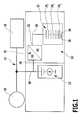
- An embodiment of an energy storage device 10 according to the invention is arranged, for example, in addition to a battery 12 in a power supply network 14 of a motor vehicle, which in addition to the battery 12 and the energy storage unit 10, for example, still a generator 16 and a plurality of consumers 18, all between the power grid 14 and mass 20 are.
- the energy storage unit 10 comprises a capacitor module 22, which comprises a plurality of capacitor cells 24 connected in series.
- the capacitor module 22 is connected, for example, to a first terminal 26 to ground 20 and is connected to a second terminal 28 to an output 32 of a DC / DC converter unit 34 whose input 36 is connected to a supply line 38 of the power supply network 14, for example, on a Voltage between about 8 and about 14 volts can be.
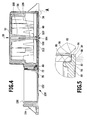
- the energy storage unit 10 is arranged in a housing 40 which, on the one hand, has a condenser chamber 42 for receiving the entire condenser cells 24 of the condenser module 22 and, on the other hand, a circuit chamber 44 in which the entire electronic circuit of the converter unit 34 and possibly further circuits of further units are arranged are.
- the condenser chamber 42 and the circuit chamber 44 are hermetically separated to provide in the condenser chamber 42 optimal conditions for the capacitor cells 24, which can be selected independently of the conditions that exist in the circuit chamber 44 for the electrical circuit.
- the housing 40 has a housing shell 50, which comprises a cover 52 and side walls 54, which extend to an opening 56 of the housing shell 50, wherein the opening 56 of the housing shell 50 by a cover 52 opposite the bottom lid 60 is closable.
- the individual capacitor cells 24 are fixed in the capacitor chamber 42 on the one hand by a capacitor holder 62 and on the other hand by a capacitor circuit board 64 relative to each other, wherein the capacitor holder 62 and the capacitor circuit board 64 relative to each other by holding elements 66, such as screws, are fixed and on the other hand, the capacitor holder 62 by holding elements 68, for example, also screws, is fixed in the housing shell 50.
- the capacitor cells 24 are inserted into the housing shell 50 with the capacitor holder 62 and the capacitor circuit board 64 so that the capacitor circuit board 64 faces the bottom cover 60 and runs close thereto.
- the capacitor circuit board 64 carries the electrical conductor tracks for interconnecting the capacitor cells 24 and establishes a connection with high-current contacts 70, which are arranged in a contact chamber 72 which adjoins the capacitor chamber 42 and is also provided in the housing housing 50 the capacitor circuit board 64 extends with a contact region 74, so that conductor tracks leading into the contact region 74 can be connected to the high-current contacts 70, for example by soldering.
- the high current contacts 70 pass through a wall 76 separating the contact chamber 72 from the circuit chamber 44, preferably being injected therein, and in addition, the high current contacts 70 are still embedded in a potting compound 78 covering the wall 76 to seal the high current contacts 70 gas tight through the wall 76 to be able to lead through.
- the bottom-side cover 60 extends to close the condenser chamber 42 not only about this, but also with a cover extension 80 via the contact chamber 72 to close both together, wherein the opening 56 of the housing shell 50 extends around the contact chamber 72 around ,
- both the bottom lid 60 ais and the lid extension 80 overlap the bead portion 82 with an edge strip 84 which projects laterally outwardly beyond an opening 56 into the guide web 86 that guides the lid 60 and the lid boss 80 relative to the opening 56 in the direction of surface expansion of the lid 60 with the lid boss 80 relative to the cabinet shell 50 upon insertion.
- high-energy radiation 88 for example laser radiation
- the edge strip 84 still extends beyond a Materialaufschmelz Scheme 92 with an outer edge 94 and the bead region 82 rises above a on one side of the opening 56 opposite side of the bead region 82 encircling support edge 96, so that upon melting of the bead region 82 in the Materialaufschmelz Scheme 92 of the lid 60 can be pushed so far with the lid extension 80 until the outer edge 94 rests on the support edge 96.
- the lid 60 is still provided with stiffening ribs 102 which extend from the edge strip 84 to the central region 100, in particular, as in Fig. 3 shown, extend to an anchoring element 104 and, for example extend radially to the anchoring element 104 over the extent of the lid 60.
- the anchoring element 104 is, as in Fig. 4 represented by a screw anchor 106 which can be screwed into a receptacle 108 of the housing shell 50, wherein the receptacle 108 is integrally formed, for example, on the upper cover 52 of the housing shell 50.
- the screw anchor 106 passes through an opening 110 which is provided in the central region 100 of the cover 60, and is sealed with respect to the opening 110 with a seal 112, thus also in the region of the screw anchor 106 to ensure that the condenser chamber 42 sealed against the environment gas-tight is.
- a gap 120 is provided between the cover 52 and the sides of the capacitor cells 24 facing it, in which a filling material 122 is arranged, which is designed to be elastic and thus can compensate for volume expansions of the capacitor cells 24.
- the filling material 122 is also provided with a sorption material for emerging from the capacitor cells 24 chemical substances.
- the filling material 122 is provided with organic polymers as the sorbent material 124, which adsorb by absorption, that is, absorption and adsorption, the acetonitrile emerging from the condenser cells 24, wherein the selection of the materials is not only in terms of a good absorption behavior and a good adsorption behavior, but also in terms of the most favorable Desorption behavior to minimize the release of once absorbed or adsorbed acetonitrile.
- the sorbent material 124 which adsorb by absorption, that is, absorption and adsorption, the acetonitrile emerging from the condenser cells 24, wherein the selection of the materials is not only in terms of a good absorption behavior and a good adsorption behavior, but also in terms of the most favorable Desorption behavior to minimize the release of once absorbed or adsorbed acetonitrile.
- the filling material 122 provided with the sorption material 124 is arranged in the form of a filling material pad 126 between the cover 52 and the capacitor cells 24.
- the circuit chamber 44 is formed by an integrally formed on the first housing shell 50 second housing shell 150, which, as in Fig. 2 . 3 and 4 shown, a bottom-side cover 152, from which rise sidewalls 154 which extend to an opening 156 which is closed by a cover unit 160, the cover unit 160 on the one hand high-current terminals 162 and 164 and on the other cooling fins 166, wherein the cooling fins 166 for cooling power components of the converter unit 34 serve.
- the converter unit 34 in turn has a converter circuit 172 arranged on a circuit board 170 and comprising the power components that can be cooled by the cooling fins 166.
- high-current paths of the converter circuit 172 are realized by punched grid 174, which carry the high currents.
- the circuit board 170 To connect the circuit board 170 with the high current contacts 70, the circuit board 170 is provided with plug contacts 176 which are plugged onto the projecting into the circuit space 44 parts of the high current contacts 70 and on the other hand, the circuit board 170 is provided with further plug contacts 178, 180, in which the High current terminals 162 and 164 leading contact bars 182, 184 are inserted, wherein the contact bars 182 and 184 anchored in the cover unit 160, preferably embedded in this.
- control contacts 186 are also provided in the cover unit 160, which are also connected to the circuit board 170 in order to be able to supply the control circuit 172 with control signals from external control devices.
Applications Claiming Priority (1)
| Application Number | Priority Date | Filing Date | Title |
|---|---|---|---|
| DE102008062657A DE102008062657A1 (de) | 2008-12-04 | 2008-12-04 | Energiespeichereinrichtung |
Publications (2)
| Publication Number | Publication Date |
|---|---|
| EP2194768A1 true EP2194768A1 (fr) | 2010-06-09 |
| EP2194768B1 EP2194768B1 (fr) | 2013-02-13 |
Family
ID=42061025
Family Applications (1)
| Application Number | Title | Priority Date | Filing Date |
|---|---|---|---|
| EP09177871A Active EP2194768B1 (fr) | 2008-12-04 | 2009-12-03 | Dispositif d'emmagasinage d'énergie |
Country Status (6)
| Country | Link |
|---|---|
| US (1) | US8780566B2 (fr) |
| EP (1) | EP2194768B1 (fr) |
| JP (1) | JP2010153850A (fr) |
| CN (1) | CN101795021B (fr) |
| DE (1) | DE102008062657A1 (fr) |
| ES (1) | ES2402534T3 (fr) |
Cited By (1)
| Publication number | Priority date | Publication date | Assignee | Title |
|---|---|---|---|---|
| CN110733362A (zh) * | 2018-07-20 | 2020-01-31 | 美达系统有限公司 | 电动或混合动力机动车的电池充电器 |
Families Citing this family (10)
| Publication number | Priority date | Publication date | Assignee | Title |
|---|---|---|---|---|
| JP5455888B2 (ja) * | 2010-12-27 | 2014-03-26 | 日立オートモティブシステムズ株式会社 | 車両用電力変換装置 |
| DE102012201766B4 (de) * | 2012-02-07 | 2019-06-13 | Semikron Elektronik Gmbh & Co. Kg | Leistungselektronisches System mit einem mindestens einen Einzug aufweisenden Gehäuse |
| JP5738794B2 (ja) * | 2012-03-30 | 2015-06-24 | 日立オートモティブシステムズ株式会社 | 電力変換装置 |
| WO2014030445A1 (fr) * | 2012-08-24 | 2014-02-27 | 日産自動車株式会社 | Unité de courant élevé intégrée installée dans un véhicule électrique |
| JP2014138445A (ja) * | 2013-01-15 | 2014-07-28 | Toyota Motor Corp | 電力変換装置 |
| JP5835246B2 (ja) * | 2013-02-27 | 2015-12-24 | 株式会社デンソー | 電池ユニット |
| DE102013009823A1 (de) | 2013-06-11 | 2014-12-11 | Liebherr-Components Biberach Gmbh | Elektrisches Antriebssystem sowie Engergiespeichervorrichtung hierfür |
| DE102015108372B4 (de) * | 2015-05-27 | 2022-03-31 | Lisa Dräxlmaier GmbH | Elektrische versorgungseinrichtung und damit ausgestattetes bordnetz eines fahrzeugs |
| CN107097685B (zh) * | 2017-04-24 | 2019-02-12 | 清华大学 | 基于弹性储能的电动汽车复合储能系统及能量分配方法 |
| DE102019122812B4 (de) * | 2019-08-26 | 2024-03-14 | Sma Solar Technology Ag | Gehäuse für ein elektrisches gerät mit einem deckel und elektrisches gerät mit einem gehäuse |
Citations (6)
| Publication number | Priority date | Publication date | Assignee | Title |
|---|---|---|---|---|
| US5880951A (en) * | 1996-10-01 | 1999-03-09 | Honda Giken Kogyo Kabushiki Kaisha | Capacitor-type power supply unit |
| DE10213570A1 (de) * | 2001-03-28 | 2003-02-06 | Hewlett Packard Co | Lebensverlängernder Batterieadapter für Multichemie-Batteriesysteme |
| EP1422983A2 (fr) * | 2002-10-14 | 2004-05-26 | IAD Gesellschaft für Informatik, Automatisierung und Datenverarbeitung mbH | Boítier plastique résistant à l'usure, conduisant et rayonnant la chaleur, pourvu de nervures de renfort et d'un radiateur surmoulé pour le refroidissement, procédé de fabrication de ce boítier |
| EP1460660A1 (fr) * | 2001-12-28 | 2004-09-22 | Rubycon Corporation | Condensateur electrolytique et solution electrolytique de commande du condensateur electrolytique |
| DE102005018339A1 (de) * | 2005-04-20 | 2006-10-26 | Siemens Ag | Anordnung mit einem Kondensatormodul und Verfahren zu dessen Betrieb |
| EP1820624A2 (fr) * | 2006-02-21 | 2007-08-22 | Kabushiki Kaisha Tokai-Rika-Denki-Seisakusho | Boîtier, dispositif portable, et procédé de soudure laser de pièces en résine |
Family Cites Families (68)
| Publication number | Priority date | Publication date | Assignee | Title |
|---|---|---|---|---|
| US1580873A (en) * | 1924-06-07 | 1926-04-13 | Gen Electric | Static condenser |
| US1737752A (en) * | 1924-09-03 | 1929-12-03 | Dubilier Condenser Corp | Condenser |
| US2099599A (en) * | 1935-01-07 | 1937-11-16 | Philips Nv | Electrolytic device |
| US2379189A (en) * | 1942-01-23 | 1945-06-26 | Nat Battery Co | Storage battery for aircraft |
| US2367725A (en) * | 1943-02-17 | 1945-01-23 | Udylite Corp | Method for joining thermoplastic materials |
| US3280751A (en) * | 1964-03-23 | 1966-10-25 | F E Myers & Bro Co | Sump pump |
| US3648337A (en) * | 1970-08-24 | 1972-03-14 | Mallory & Co Inc P R | Encapsulating of electronic components |
| US3693050A (en) * | 1971-01-21 | 1972-09-19 | Electric Regulator Corp | Single module power supply |
| US3972380A (en) * | 1975-04-11 | 1976-08-03 | Hudson Perley N | Vehicle with regenerative power system |
| US4050770A (en) * | 1976-10-18 | 1977-09-27 | Rigo Larry E | Junction box terminal block |
| FR2423954A1 (fr) * | 1978-04-21 | 1979-11-16 | Cem Comp Electro Mec | Enceinte etanche en resine moulee avec membrane de securite, notamment pour appareils electriques |
| US4313025A (en) * | 1980-06-04 | 1982-01-26 | Motorola, Inc. | Unitary die-cast assembly for electronic circuits |
| JPH0410685Y2 (fr) * | 1987-02-25 | 1992-03-17 | ||
| KR920005988B1 (ko) * | 1988-08-31 | 1992-07-25 | 가부시기가이샤 히다찌세이사꾸쇼 | 인버터장치 |
| DE4009504A1 (de) * | 1990-03-24 | 1991-10-02 | Rexroth Pneumatik Mannesmann | Einrichtung zur elektrischen versorgung eines verbrauchers eines anhaengerfahrzeugs |
| JP2881967B2 (ja) * | 1990-05-29 | 1999-04-12 | 松下電器産業株式会社 | アルミ電解コンデンサ |
| US5251721A (en) * | 1992-04-21 | 1993-10-12 | Richard Ortenheim | Semi-hybrid electric automobile |
| ES2119415T5 (es) * | 1994-03-31 | 2005-03-16 | Marquardt Gmbh | Pieza de plastico y procedimiento de fabricacion para una pieza de esta clase. |
| DE4442867C2 (de) * | 1994-12-02 | 1999-09-09 | Mannesmann Sachs Ag | Antriebsanordnung für ein Fahrzeug, insbesondere ein Straßenfahrzeug |
| US5760637A (en) * | 1995-12-11 | 1998-06-02 | Sipex Corporation | Programmable charge pump |
| JPH09186055A (ja) * | 1995-12-28 | 1997-07-15 | Okamura Kenkyusho:Kk | 複数個を収容したコンデンサ |
| FR2754946B1 (fr) * | 1996-10-18 | 1998-11-27 | Schneider Electric Sa | Dispositif de support et d'alimentation electrique pour appareillage electrique |
| TW337401U (en) * | 1997-10-09 | 1998-07-21 | Weltek Electronics Co Ltd | Waterproof case |
| FR2777152B1 (fr) * | 1998-04-02 | 2000-06-23 | Steve Ingenierie | Dispositif de refroidissement pour systeme electronique de puissance |
| US6400554B1 (en) * | 1998-06-19 | 2002-06-04 | Matsushita Electric Industrial Co., Ltd. | Electrolytic capacitor, its anode body, and method of producing the same |
| US6323623B1 (en) * | 1999-08-23 | 2001-11-27 | Casio Computer Co., Ltd. | Charging device and charging method thereof |
| US6962613B2 (en) * | 2000-03-24 | 2005-11-08 | Cymbet Corporation | Low-temperature fabrication of thin-film energy-storage devices |
| CA2343097A1 (fr) * | 2000-04-05 | 2001-10-05 | Nissin Electric Co., Ltd. | Condensateur ininflammable pour la prevention des catastrophes |
| US6419037B1 (en) * | 2000-07-19 | 2002-07-16 | Meritor Heavy Vehicle Systems, Llc | Multi-unit articulated road train propulsion system |
| US6563235B1 (en) * | 2000-10-03 | 2003-05-13 | National Semiconductor Corporation | Switched capacitor array circuit for use in DC-DC converter and method |
| US6504422B1 (en) * | 2000-11-21 | 2003-01-07 | Semtech Corporation | Charge pump with current limiting circuit |
| DE10131430A1 (de) * | 2001-06-29 | 2003-01-16 | Bosch Gmbh Robert | Verfahren zum Verschweißen |
| DE10218295A1 (de) * | 2002-04-24 | 2003-11-13 | Epcos Ag | Kondensatormodul und Kondensatorbatterie mit dem Kondensatormodul |
| US6935451B2 (en) * | 2002-10-29 | 2005-08-30 | Arvinmeritor Technology, Llc | Axle assembly with parallel drive system for electric hybrid vehicles |
| JP3816888B2 (ja) * | 2003-04-04 | 2006-08-30 | 株式会社日立製作所 | 車両駆動ユニット及び車両駆動装置 |
| US20040264223A1 (en) * | 2003-06-30 | 2004-12-30 | Intel Corporation | Switched capacitor power converter |
| US7016177B1 (en) * | 2003-11-07 | 2006-03-21 | Maxwell Technologies, Inc. | Capacitor heat protection |
| DE102004003696B4 (de) * | 2004-01-24 | 2017-02-16 | Limo Patentverwaltung Gmbh & Co. Kg | Vorrichtung zum simultanen Laserschweißen |
| DE102004010712A1 (de) * | 2004-03-04 | 2005-09-22 | Epcos Ag | Gehäuse für Hochleistungsbauteile |
| JP2006035941A (ja) * | 2004-07-23 | 2006-02-09 | Sanyo Electric Co Ltd | 車両用の電源装置 |
| JP4334430B2 (ja) * | 2004-07-23 | 2009-09-30 | 三洋電機株式会社 | 車両用の電源装置 |
| JP4747560B2 (ja) * | 2004-11-17 | 2011-08-17 | パナソニック株式会社 | フィルムコンデンサおよびその製造方法 |
| WO2006061952A1 (fr) * | 2004-12-06 | 2006-06-15 | Rohm Co., Ltd | Circuit de boost et appareil portable l’utilisant |
| WO2007023849A1 (fr) * | 2005-08-25 | 2007-03-01 | Matsushita Electric Industrial Co., Ltd. | Moniteur de tension et stockage d'énergie électrique utilisant celui-ci |
| JP4859443B2 (ja) * | 2005-11-17 | 2012-01-25 | 日立オートモティブシステムズ株式会社 | 電力変換装置 |
| ITMI20052344A1 (it) * | 2005-12-06 | 2007-06-07 | Getters Spa | Condensatori elettrolitici comprendenti mezzi in forma di foglio polimerico multistrato per l'assorbimento di sostanze nocive |
| ITMI20060056A1 (it) * | 2006-01-16 | 2007-07-17 | Getters Spa | Condensatore elettrolitico comprendente mezzi per l'assorbimento di sostanze nocive |
| JP4837730B2 (ja) * | 2006-04-27 | 2011-12-14 | 株式会社小松製作所 | キャパシタモジュール |
| JP4434181B2 (ja) * | 2006-07-21 | 2010-03-17 | 株式会社日立製作所 | 電力変換装置 |
| DE102007046578A1 (de) * | 2006-09-28 | 2008-04-10 | Siemens Ag | Energiespeichermodul |
| JP4909712B2 (ja) * | 2006-11-13 | 2012-04-04 | 日立オートモティブシステムズ株式会社 | 電力変換装置 |
| GB2444985B (en) * | 2006-12-22 | 2011-09-14 | Wolfson Microelectronics Plc | Charge pump circuit and methods of operation thereof |
| EP1935712A1 (fr) * | 2006-12-22 | 2008-06-25 | Nederlandse Organisatie voor Toegepast-Natuuurwetenschappelijk Onderzoek TNO | Système et procédé pour véhicule |
| JP2008166303A (ja) * | 2006-12-26 | 2008-07-17 | Toyota Industries Corp | 電解コンデンサの収容構造 |
| JP4516060B2 (ja) * | 2006-12-26 | 2010-08-04 | 株式会社東芝 | 車両用制御装置 |
| US7619878B1 (en) * | 2007-07-16 | 2009-11-17 | Nicor, Inc. | Meter cover for automated meter reading |
| JP4452953B2 (ja) * | 2007-08-09 | 2010-04-21 | 日立オートモティブシステムズ株式会社 | 電力変換装置 |
| US7854282B2 (en) * | 2007-12-10 | 2010-12-21 | International Humanities Center | Hybrid electric vehicle |
| US7764067B2 (en) * | 2007-12-27 | 2010-07-27 | Caterpillar Inc | High voltage cable testing method |
| JP5095459B2 (ja) * | 2008-03-25 | 2012-12-12 | 株式会社小松製作所 | キャパシタモジュール |
| DE102008040018A1 (de) * | 2008-06-30 | 2009-12-31 | Robert Bosch Gmbh | Modulare elektromechanische Schaltungsanordnung |
| JP4657329B2 (ja) * | 2008-07-29 | 2011-03-23 | 日立オートモティブシステムズ株式会社 | 電力変換装置および電動車両 |
| US8258792B2 (en) * | 2009-05-11 | 2012-09-04 | Semiconductor Components Industries, Llc. | Monitoring system and method |
| TWI480908B (zh) * | 2009-06-02 | 2015-04-11 | Kurita Water Ind Ltd | Metal electrolytic capacitors and metal electrolytic capacitors with absorbent materials and leak-proof materials |
| US8044706B2 (en) * | 2009-10-09 | 2011-10-25 | Dialog Semiconductor Gmbh | Reduced capacitor charge-pump |
| US8338721B2 (en) * | 2010-04-01 | 2012-12-25 | Phoenix International Corporation | Cover with improved vibrational characteristics for an electronic device |
| US9086450B2 (en) * | 2010-10-04 | 2015-07-21 | Taiwan Semiconductor Manufacturing Company, Ltd. | Method for measuring capacitances of capacitors |
| JP5455888B2 (ja) * | 2010-12-27 | 2014-03-26 | 日立オートモティブシステムズ株式会社 | 車両用電力変換装置 |
-
2008
- 2008-12-04 DE DE102008062657A patent/DE102008062657A1/de not_active Withdrawn
-
2009
- 2009-12-02 US US12/591,825 patent/US8780566B2/en active Active
- 2009-12-03 ES ES09177871T patent/ES2402534T3/es active Active
- 2009-12-03 EP EP09177871A patent/EP2194768B1/fr active Active
- 2009-12-04 JP JP2009276444A patent/JP2010153850A/ja active Pending
- 2009-12-04 CN CN200910252837.4A patent/CN101795021B/zh active Active
Patent Citations (6)
| Publication number | Priority date | Publication date | Assignee | Title |
|---|---|---|---|---|
| US5880951A (en) * | 1996-10-01 | 1999-03-09 | Honda Giken Kogyo Kabushiki Kaisha | Capacitor-type power supply unit |
| DE10213570A1 (de) * | 2001-03-28 | 2003-02-06 | Hewlett Packard Co | Lebensverlängernder Batterieadapter für Multichemie-Batteriesysteme |
| EP1460660A1 (fr) * | 2001-12-28 | 2004-09-22 | Rubycon Corporation | Condensateur electrolytique et solution electrolytique de commande du condensateur electrolytique |
| EP1422983A2 (fr) * | 2002-10-14 | 2004-05-26 | IAD Gesellschaft für Informatik, Automatisierung und Datenverarbeitung mbH | Boítier plastique résistant à l'usure, conduisant et rayonnant la chaleur, pourvu de nervures de renfort et d'un radiateur surmoulé pour le refroidissement, procédé de fabrication de ce boítier |
| DE102005018339A1 (de) * | 2005-04-20 | 2006-10-26 | Siemens Ag | Anordnung mit einem Kondensatormodul und Verfahren zu dessen Betrieb |
| EP1820624A2 (fr) * | 2006-02-21 | 2007-08-22 | Kabushiki Kaisha Tokai-Rika-Denki-Seisakusho | Boîtier, dispositif portable, et procédé de soudure laser de pièces en résine |
Cited By (1)
| Publication number | Priority date | Publication date | Assignee | Title |
|---|---|---|---|---|
| CN110733362A (zh) * | 2018-07-20 | 2020-01-31 | 美达系统有限公司 | 电动或混合动力机动车的电池充电器 |
Also Published As
| Publication number | Publication date |
|---|---|
| JP2010153850A (ja) | 2010-07-08 |
| DE102008062657A1 (de) | 2010-06-10 |
| EP2194768B1 (fr) | 2013-02-13 |
| CN101795021B (zh) | 2014-08-27 |
| US20100149757A1 (en) | 2010-06-17 |
| US8780566B2 (en) | 2014-07-15 |
| CN101795021A (zh) | 2010-08-04 |
| ES2402534T3 (es) | 2013-05-06 |
Similar Documents
| Publication | Publication Date | Title |
|---|---|---|
| EP2194768B1 (fr) | Dispositif d'emmagasinage d'énergie | |
| EP2715862B1 (fr) | Batterie pour véhicule, et procédé de production d'une batterie | |
| DE112010001711T5 (de) | Struktur zum hemmen der ausbreitung von ausgelaufener flüssigkeit für eine elektrizitätsspeichervorrichtung und sammelleitermodul | |
| DE102007010738A1 (de) | Leiterplattenschutz für eine Batterie | |
| DE102008010828A1 (de) | Batterie mit mehreren Einzelzellen | |
| DE10002142A1 (de) | Stromquelle enthaltend wiederaufladbare Batterien | |
| DE102010052728A1 (de) | Teilvergossenes Netzteil und Herstellungsverfahren | |
| DE102010013002A1 (de) | Batterie mit einem Zellenstapel | |
| DE102016222264A1 (de) | Batteriemodul, Verfahren zu dessen Herstellung und Batterie | |
| DE102008010824A1 (de) | Batterie mit mehreren Einzelzellen | |
| DE102007031351A1 (de) | Verbindungsvorrichtung zur Verbindung eines ersten elektrischen Leiters mit einem elektrischen Leiter eines photovoltaischen Solarmoduls | |
| DE202010017245U1 (de) | Batteriepack | |
| EP2194547A1 (fr) | Dispositif d'emmagasinage d'énergie | |
| WO2012062396A1 (fr) | Batterie comportant un ensemble de cellules | |
| DE102011012631B4 (de) | Energiespeicher | |
| DE102008010808A1 (de) | Batterie mit einer in einem Batteriegehäuse angeordneten Wärmeleitplatte zum Temperieren der Batterie und Verfahren zur Herstellung einer Baterie | |
| DE102019122812A1 (de) | Gehäuse für ein elektrisches gerät mit einem deckel und elektrisches gerät mit einem gehäuse | |
| EP2458645A1 (fr) | Module solaire doté d'une unité de raccordement ayant un élément de moulage | |
| DE102008062655B4 (de) | Energiespeichereinrichtung | |
| DE102014205724A1 (de) | Energiespeichervorrichtung | |
| DE102013217836B4 (de) | Traktionsbatterie für ein Fahrzeug sowie Verfahren zur Herstellung dafür | |
| DE102012222699A1 (de) | Speicherzelle | |
| DE102014215616A1 (de) | Batteriesystem | |
| DE102013015756A1 (de) | Zellblock für eine Batterie | |
| DE102017218923A1 (de) | Elektrisches Überbrückungselement, elektrischer Energiespeicher und Vorrichtung |
Legal Events
| Date | Code | Title | Description |
|---|---|---|---|
| PUAI | Public reference made under article 153(3) epc to a published international application that has entered the european phase |
Free format text: ORIGINAL CODE: 0009012 |
|
| AK | Designated contracting states |
Kind code of ref document: A1 Designated state(s): AT BE BG CH CY CZ DE DK EE ES FI FR GB GR HR HU IE IS IT LI LT LU LV MC MK MT NL NO PL PT RO SE SI SK SM TR |
|
| AX | Request for extension of the european patent |
Extension state: AL BA RS |
|
| 17P | Request for examination filed |
Effective date: 20100831 |
|
| GRAP | Despatch of communication of intention to grant a patent |
Free format text: ORIGINAL CODE: EPIDOSNIGR1 |
|
| RIC1 | Information provided on ipc code assigned before grant |
Ipc: H01M 16/00 20060101ALI20120627BHEP Ipc: H02J 7/34 20060101ALI20120627BHEP Ipc: H05K 5/06 20060101AFI20120627BHEP Ipc: H01M 2/10 20060101ALI20120627BHEP |
|
| RAP1 | Party data changed (applicant data changed or rights of an application transferred) |
Owner name: FLEXTRONICS INTERNATIONAL KFT. |
|
| GRAS | Grant fee paid |
Free format text: ORIGINAL CODE: EPIDOSNIGR3 |
|
| GRAA | (expected) grant |
Free format text: ORIGINAL CODE: 0009210 |
|
| AK | Designated contracting states |
Kind code of ref document: B1 Designated state(s): AT BE BG CH CY CZ DE DK EE ES FI FR GB GR HR HU IE IS IT LI LT LU LV MC MK MT NL NO PL PT RO SE SI SK SM TR |
|
| REG | Reference to a national code |
Ref country code: GB Ref legal event code: FG4D Free format text: NOT ENGLISH |
|
| REG | Reference to a national code |
Ref country code: AT Ref legal event code: REF Ref document number: 597086 Country of ref document: AT Kind code of ref document: T Effective date: 20130215 |
|
| REG | Reference to a national code |
Ref country code: IE Ref legal event code: FG4D Free format text: LANGUAGE OF EP DOCUMENT: GERMAN |
|
| REG | Reference to a national code |
Ref country code: DE Ref legal event code: R096 Ref document number: 502009006210 Country of ref document: DE Effective date: 20130411 |
|
| REG | Reference to a national code |
Ref country code: ES Ref legal event code: FG2A Ref document number: 2402534 Country of ref document: ES Kind code of ref document: T3 Effective date: 20130506 |
|
| REG | Reference to a national code |
Ref country code: SE Ref legal event code: TRGR |
|
| REG | Reference to a national code |
Ref country code: NL Ref legal event code: VDEP Effective date: 20130213 |
|
| REG | Reference to a national code |
Ref country code: LT Ref legal event code: MG4D |
|
| PG25 | Lapsed in a contracting state [announced via postgrant information from national office to epo] |
Ref country code: IS Free format text: LAPSE BECAUSE OF FAILURE TO SUBMIT A TRANSLATION OF THE DESCRIPTION OR TO PAY THE FEE WITHIN THE PRESCRIBED TIME-LIMIT Effective date: 20130613 Ref country code: BG Free format text: LAPSE BECAUSE OF FAILURE TO SUBMIT A TRANSLATION OF THE DESCRIPTION OR TO PAY THE FEE WITHIN THE PRESCRIBED TIME-LIMIT Effective date: 20130513 Ref country code: LT Free format text: LAPSE BECAUSE OF FAILURE TO SUBMIT A TRANSLATION OF THE DESCRIPTION OR TO PAY THE FEE WITHIN THE PRESCRIBED TIME-LIMIT Effective date: 20130213 Ref country code: NO Free format text: LAPSE BECAUSE OF FAILURE TO SUBMIT A TRANSLATION OF THE DESCRIPTION OR TO PAY THE FEE WITHIN THE PRESCRIBED TIME-LIMIT Effective date: 20130513 |
|
| PG25 | Lapsed in a contracting state [announced via postgrant information from national office to epo] |
Ref country code: GR Free format text: LAPSE BECAUSE OF FAILURE TO SUBMIT A TRANSLATION OF THE DESCRIPTION OR TO PAY THE FEE WITHIN THE PRESCRIBED TIME-LIMIT Effective date: 20130514 Ref country code: PL Free format text: LAPSE BECAUSE OF FAILURE TO SUBMIT A TRANSLATION OF THE DESCRIPTION OR TO PAY THE FEE WITHIN THE PRESCRIBED TIME-LIMIT Effective date: 20130213 Ref country code: SI Free format text: LAPSE BECAUSE OF FAILURE TO SUBMIT A TRANSLATION OF THE DESCRIPTION OR TO PAY THE FEE WITHIN THE PRESCRIBED TIME-LIMIT Effective date: 20130213 Ref country code: LV Free format text: LAPSE BECAUSE OF FAILURE TO SUBMIT A TRANSLATION OF THE DESCRIPTION OR TO PAY THE FEE WITHIN THE PRESCRIBED TIME-LIMIT Effective date: 20130213 Ref country code: FI Free format text: LAPSE BECAUSE OF FAILURE TO SUBMIT A TRANSLATION OF THE DESCRIPTION OR TO PAY THE FEE WITHIN THE PRESCRIBED TIME-LIMIT Effective date: 20130213 Ref country code: PT Free format text: LAPSE BECAUSE OF FAILURE TO SUBMIT A TRANSLATION OF THE DESCRIPTION OR TO PAY THE FEE WITHIN THE PRESCRIBED TIME-LIMIT Effective date: 20130613 |
|
| PG25 | Lapsed in a contracting state [announced via postgrant information from national office to epo] |
Ref country code: HR Free format text: LAPSE BECAUSE OF FAILURE TO SUBMIT A TRANSLATION OF THE DESCRIPTION OR TO PAY THE FEE WITHIN THE PRESCRIBED TIME-LIMIT Effective date: 20130213 |
|
| PG25 | Lapsed in a contracting state [announced via postgrant information from national office to epo] |
Ref country code: EE Free format text: LAPSE BECAUSE OF FAILURE TO SUBMIT A TRANSLATION OF THE DESCRIPTION OR TO PAY THE FEE WITHIN THE PRESCRIBED TIME-LIMIT Effective date: 20130213 Ref country code: NL Free format text: LAPSE BECAUSE OF FAILURE TO SUBMIT A TRANSLATION OF THE DESCRIPTION OR TO PAY THE FEE WITHIN THE PRESCRIBED TIME-LIMIT Effective date: 20130213 Ref country code: DK Free format text: LAPSE BECAUSE OF FAILURE TO SUBMIT A TRANSLATION OF THE DESCRIPTION OR TO PAY THE FEE WITHIN THE PRESCRIBED TIME-LIMIT Effective date: 20130213 Ref country code: SK Free format text: LAPSE BECAUSE OF FAILURE TO SUBMIT A TRANSLATION OF THE DESCRIPTION OR TO PAY THE FEE WITHIN THE PRESCRIBED TIME-LIMIT Effective date: 20130213 Ref country code: RO Free format text: LAPSE BECAUSE OF FAILURE TO SUBMIT A TRANSLATION OF THE DESCRIPTION OR TO PAY THE FEE WITHIN THE PRESCRIBED TIME-LIMIT Effective date: 20130213 |
|
| PLBE | No opposition filed within time limit |
Free format text: ORIGINAL CODE: 0009261 |
|
| STAA | Information on the status of an ep patent application or granted ep patent |
Free format text: STATUS: NO OPPOSITION FILED WITHIN TIME LIMIT |
|
| REG | Reference to a national code |
Ref country code: HU Ref legal event code: AG4A Ref document number: E017679 Country of ref document: HU |
|
| 26N | No opposition filed |
Effective date: 20131114 |
|
| REG | Reference to a national code |
Ref country code: DE Ref legal event code: R097 Ref document number: 502009006210 Country of ref document: DE Effective date: 20131114 |
|
| BERE | Be: lapsed |
Owner name: FLEXTRONICS INTERNATIONAL KFT. Effective date: 20131231 |
|
| REG | Reference to a national code |
Ref country code: SE Ref legal event code: EUG |
|
| REG | Reference to a national code |
Ref country code: CH Ref legal event code: PL |
|
| GBPC | Gb: european patent ceased through non-payment of renewal fee |
Effective date: 20131203 |
|
| PG25 | Lapsed in a contracting state [announced via postgrant information from national office to epo] |
Ref country code: MC Free format text: LAPSE BECAUSE OF FAILURE TO SUBMIT A TRANSLATION OF THE DESCRIPTION OR TO PAY THE FEE WITHIN THE PRESCRIBED TIME-LIMIT Effective date: 20130213 Ref country code: LU Free format text: LAPSE BECAUSE OF FAILURE TO SUBMIT A TRANSLATION OF THE DESCRIPTION OR TO PAY THE FEE WITHIN THE PRESCRIBED TIME-LIMIT Effective date: 20131203 Ref country code: CZ Free format text: LAPSE BECAUSE OF NON-PAYMENT OF DUE FEES Effective date: 20131203 Ref country code: SE Free format text: LAPSE BECAUSE OF NON-PAYMENT OF DUE FEES Effective date: 20131204 |
|
| REG | Reference to a national code |
Ref country code: GB Ref legal event code: S28 Free format text: APPLICATION FILED |
|
| REG | Reference to a national code |
Ref country code: IE Ref legal event code: MM4A |
|
| REG | Reference to a national code |
Ref country code: FR Ref legal event code: ST Effective date: 20140829 |
|
| REG | Reference to a national code |
Ref country code: GB Ref legal event code: S28 Free format text: RESTORATION ALLOWED Effective date: 20140925 |
|
| PG25 | Lapsed in a contracting state [announced via postgrant information from national office to epo] |
Ref country code: LI Free format text: LAPSE BECAUSE OF NON-PAYMENT OF DUE FEES Effective date: 20131231 Ref country code: CH Free format text: LAPSE BECAUSE OF NON-PAYMENT OF DUE FEES Effective date: 20131231 Ref country code: BE Free format text: LAPSE BECAUSE OF NON-PAYMENT OF DUE FEES Effective date: 20131231 Ref country code: IE Free format text: LAPSE BECAUSE OF NON-PAYMENT OF DUE FEES Effective date: 20131203 |
|
| PG25 | Lapsed in a contracting state [announced via postgrant information from national office to epo] |
Ref country code: GB Free format text: LAPSE BECAUSE OF NON-PAYMENT OF DUE FEES Effective date: 20131203 Ref country code: HU Free format text: LAPSE BECAUSE OF NON-PAYMENT OF DUE FEES Effective date: 20131204 Ref country code: FR Free format text: LAPSE BECAUSE OF NON-PAYMENT OF DUE FEES Effective date: 20131231 |
|
| REG | Reference to a national code |
Ref country code: ES Ref legal event code: FD2A Effective date: 20150327 |
|
| PG25 | Lapsed in a contracting state [announced via postgrant information from national office to epo] |
Ref country code: ES Free format text: LAPSE BECAUSE OF NON-PAYMENT OF DUE FEES Effective date: 20131204 |
|
| PG25 | Lapsed in a contracting state [announced via postgrant information from national office to epo] |
Ref country code: SM Free format text: LAPSE BECAUSE OF FAILURE TO SUBMIT A TRANSLATION OF THE DESCRIPTION OR TO PAY THE FEE WITHIN THE PRESCRIBED TIME-LIMIT Effective date: 20130213 |
|
| PG25 | Lapsed in a contracting state [announced via postgrant information from national office to epo] |
Ref country code: TR Free format text: LAPSE BECAUSE OF FAILURE TO SUBMIT A TRANSLATION OF THE DESCRIPTION OR TO PAY THE FEE WITHIN THE PRESCRIBED TIME-LIMIT Effective date: 20130213 Ref country code: CY Free format text: LAPSE BECAUSE OF FAILURE TO SUBMIT A TRANSLATION OF THE DESCRIPTION OR TO PAY THE FEE WITHIN THE PRESCRIBED TIME-LIMIT Effective date: 20130213 |
|
| PG25 | Lapsed in a contracting state [announced via postgrant information from national office to epo] |
Ref country code: MK Free format text: LAPSE BECAUSE OF FAILURE TO SUBMIT A TRANSLATION OF THE DESCRIPTION OR TO PAY THE FEE WITHIN THE PRESCRIBED TIME-LIMIT Effective date: 20130213 |
|
| PG25 | Lapsed in a contracting state [announced via postgrant information from national office to epo] |
Ref country code: IT Free format text: LAPSE BECAUSE OF NON-PAYMENT OF DUE FEES Effective date: 20130213 Ref country code: MT Free format text: LAPSE BECAUSE OF FAILURE TO SUBMIT A TRANSLATION OF THE DESCRIPTION OR TO PAY THE FEE WITHIN THE PRESCRIBED TIME-LIMIT Effective date: 20130213 |
|
| PG25 | Lapsed in a contracting state [announced via postgrant information from national office to epo] |
Ref country code: IT Free format text: LAPSE BECAUSE OF NON-PAYMENT OF DUE FEES Effective date: 20131203 |
|
| PGFP | Annual fee paid to national office [announced via postgrant information from national office to epo] |
Ref country code: AT Payment date: 20180125 Year of fee payment: 9 |
|
| REG | Reference to a national code |
Ref country code: AT Ref legal event code: MM01 Ref document number: 597086 Country of ref document: AT Kind code of ref document: T Effective date: 20181203 |
|
| PG25 | Lapsed in a contracting state [announced via postgrant information from national office to epo] |
Ref country code: AT Free format text: LAPSE BECAUSE OF NON-PAYMENT OF DUE FEES Effective date: 20181203 |
|
| PGFP | Annual fee paid to national office [announced via postgrant information from national office to epo] |
Ref country code: GB Payment date: 20231219 Year of fee payment: 15 |
|
| PGFP | Annual fee paid to national office [announced via postgrant information from national office to epo] |
Ref country code: DE Payment date: 20231227 Year of fee payment: 15 |