EP1422983A2 - Boítier plastique résistant à l'usure, conduisant et rayonnant la chaleur, pourvu de nervures de renfort et d'un radiateur surmoulé pour le refroidissement, procédé de fabrication de ce boítier - Google Patents
Boítier plastique résistant à l'usure, conduisant et rayonnant la chaleur, pourvu de nervures de renfort et d'un radiateur surmoulé pour le refroidissement, procédé de fabrication de ce boítier Download PDFInfo
- Publication number
- EP1422983A2 EP1422983A2 EP03023036A EP03023036A EP1422983A2 EP 1422983 A2 EP1422983 A2 EP 1422983A2 EP 03023036 A EP03023036 A EP 03023036A EP 03023036 A EP03023036 A EP 03023036A EP 1422983 A2 EP1422983 A2 EP 1422983A2
- Authority
- EP
- European Patent Office
- Prior art keywords
- housing
- heat
- heat sink
- plastic
- cooling
- Prior art date
- Legal status (The legal status is an assumption and is not a legal conclusion. Google has not performed a legal analysis and makes no representation as to the accuracy of the status listed.)
- Granted
Links
- 239000004033 plastic Substances 0.000 title claims abstract description 77
- 229920003023 plastic Polymers 0.000 title claims abstract description 77
- 238000001816 cooling Methods 0.000 title claims abstract description 29
- 238000004519 manufacturing process Methods 0.000 title claims description 18
- 238000012546 transfer Methods 0.000 claims description 34
- 239000004020 conductor Substances 0.000 claims description 10
- 238000000034 method Methods 0.000 claims description 6
- 238000001125 extrusion Methods 0.000 claims description 3
- 210000004907 gland Anatomy 0.000 claims description 3
- 230000008569 process Effects 0.000 claims description 3
- 125000006850 spacer group Chemical group 0.000 claims description 3
- 238000001746 injection moulding Methods 0.000 abstract description 6
- 230000017525 heat dissipation Effects 0.000 description 33
- 229910052751 metal Inorganic materials 0.000 description 16
- 239000002184 metal Substances 0.000 description 16
- 230000005855 radiation Effects 0.000 description 16
- 229910052782 aluminium Inorganic materials 0.000 description 15
- XAGFODPZIPBFFR-UHFFFAOYSA-N aluminium Chemical compound [Al] XAGFODPZIPBFFR-UHFFFAOYSA-N 0.000 description 15
- 230000007613 environmental effect Effects 0.000 description 11
- 230000008901 benefit Effects 0.000 description 9
- 150000001875 compounds Chemical class 0.000 description 7
- 230000001681 protective effect Effects 0.000 description 7
- 239000000758 substrate Substances 0.000 description 7
- XLYOFNOQVPJJNP-UHFFFAOYSA-N water Chemical compound O XLYOFNOQVPJJNP-UHFFFAOYSA-N 0.000 description 7
- 238000010521 absorption reaction Methods 0.000 description 6
- 238000005266 casting Methods 0.000 description 6
- 238000013461 design Methods 0.000 description 6
- 238000009434 installation Methods 0.000 description 6
- RYGMFSIKBFXOCR-UHFFFAOYSA-N Copper Chemical compound [Cu] RYGMFSIKBFXOCR-UHFFFAOYSA-N 0.000 description 5
- 239000003990 capacitor Substances 0.000 description 5
- 238000010276 construction Methods 0.000 description 5
- 229910052802 copper Inorganic materials 0.000 description 5
- 239000010949 copper Substances 0.000 description 5
- 238000005516 engineering process Methods 0.000 description 5
- 239000004065 semiconductor Substances 0.000 description 5
- 238000010292 electrical insulation Methods 0.000 description 4
- 239000003344 environmental pollutant Substances 0.000 description 4
- 231100000719 pollutant Toxicity 0.000 description 4
- 238000010079 rubber tapping Methods 0.000 description 4
- 238000007789 sealing Methods 0.000 description 4
- 229920000049 Carbon (fiber) Polymers 0.000 description 3
- 238000009825 accumulation Methods 0.000 description 3
- 239000004917 carbon fiber Substances 0.000 description 3
- 239000000919 ceramic Substances 0.000 description 3
- 239000000446 fuel Substances 0.000 description 3
- 239000008187 granular material Substances 0.000 description 3
- 230000006872 improvement Effects 0.000 description 3
- 238000002347 injection Methods 0.000 description 3
- 239000007924 injection Substances 0.000 description 3
- 239000000463 material Substances 0.000 description 3
- 238000000465 moulding Methods 0.000 description 3
- 239000000243 solution Substances 0.000 description 3
- 238000012549 training Methods 0.000 description 3
- 239000000853 adhesive Substances 0.000 description 2
- 230000001070 adhesive effect Effects 0.000 description 2
- 239000003570 air Substances 0.000 description 2
- 230000008878 coupling Effects 0.000 description 2
- 238000010168 coupling process Methods 0.000 description 2
- 238000005859 coupling reaction Methods 0.000 description 2
- 238000011161 development Methods 0.000 description 2
- 230000009977 dual effect Effects 0.000 description 2
- 238000005538 encapsulation Methods 0.000 description 2
- 239000000945 filler Substances 0.000 description 2
- 239000011440 grout Substances 0.000 description 2
- 150000002739 metals Chemical class 0.000 description 2
- 230000000704 physical effect Effects 0.000 description 2
- 239000000843 powder Substances 0.000 description 2
- 239000000565 sealant Substances 0.000 description 2
- FRWYFWZENXDZMU-UHFFFAOYSA-N 2-iodoquinoline Chemical compound C1=CC=CC2=NC(I)=CC=C21 FRWYFWZENXDZMU-UHFFFAOYSA-N 0.000 description 1
- 229910000881 Cu alloy Inorganic materials 0.000 description 1
- XEEYBQQBJWHFJM-UHFFFAOYSA-N Iron Chemical compound [Fe] XEEYBQQBJWHFJM-UHFFFAOYSA-N 0.000 description 1
- FYYHWMGAXLPEAU-UHFFFAOYSA-N Magnesium Chemical compound [Mg] FYYHWMGAXLPEAU-UHFFFAOYSA-N 0.000 description 1
- BPQQTUXANYXVAA-UHFFFAOYSA-N Orthosilicate Chemical compound [O-][Si]([O-])([O-])[O-] BPQQTUXANYXVAA-UHFFFAOYSA-N 0.000 description 1
- 230000009471 action Effects 0.000 description 1
- 238000004378 air conditioning Methods 0.000 description 1
- 239000012080 ambient air Substances 0.000 description 1
- 238000013459 approach Methods 0.000 description 1
- LTPBRCUWZOMYOC-UHFFFAOYSA-N beryllium oxide Inorganic materials O=[Be] LTPBRCUWZOMYOC-UHFFFAOYSA-N 0.000 description 1
- 230000015572 biosynthetic process Effects 0.000 description 1
- 230000003139 buffering effect Effects 0.000 description 1
- 239000003795 chemical substances by application Substances 0.000 description 1
- PMHQVHHXPFUNSP-UHFFFAOYSA-M copper(1+);methylsulfanylmethane;bromide Chemical compound Br[Cu].CSC PMHQVHHXPFUNSP-UHFFFAOYSA-M 0.000 description 1
- 238000005260 corrosion Methods 0.000 description 1
- 230000007797 corrosion Effects 0.000 description 1
- 230000001419 dependent effect Effects 0.000 description 1
- 238000004512 die casting Methods 0.000 description 1
- 238000009826 distribution Methods 0.000 description 1
- 229920001971 elastomer Polymers 0.000 description 1
- 239000000806 elastomer Substances 0.000 description 1
- 239000012765 fibrous filler Substances 0.000 description 1
- 238000010304 firing Methods 0.000 description 1
- 239000011888 foil Substances 0.000 description 1
- 125000000524 functional group Chemical group 0.000 description 1
- 239000004519 grease Substances 0.000 description 1
- 238000010438 heat treatment Methods 0.000 description 1
- 230000001771 impaired effect Effects 0.000 description 1
- 238000009413 insulation Methods 0.000 description 1
- 230000010354 integration Effects 0.000 description 1
- 239000003350 kerosene Substances 0.000 description 1
- 229910052749 magnesium Inorganic materials 0.000 description 1
- 239000011777 magnesium Substances 0.000 description 1
- NJPPVKZQTLUDBO-UHFFFAOYSA-N novaluron Chemical compound C1=C(Cl)C(OC(F)(F)C(OC(F)(F)F)F)=CC=C1NC(=O)NC(=O)C1=C(F)C=CC=C1F NJPPVKZQTLUDBO-UHFFFAOYSA-N 0.000 description 1
- 238000005457 optimization Methods 0.000 description 1
- TWNQGVIAIRXVLR-UHFFFAOYSA-N oxo(oxoalumanyloxy)alumane Chemical compound O=[Al]O[Al]=O TWNQGVIAIRXVLR-UHFFFAOYSA-N 0.000 description 1
- 230000002093 peripheral effect Effects 0.000 description 1
- 229920001296 polysiloxane Polymers 0.000 description 1
- 230000002265 prevention Effects 0.000 description 1
- 238000004080 punching Methods 0.000 description 1
- 238000005057 refrigeration Methods 0.000 description 1
- 230000008439 repair process Effects 0.000 description 1
- 150000003839 salts Chemical class 0.000 description 1
- 239000013535 sea water Substances 0.000 description 1
- 238000000926 separation method Methods 0.000 description 1
- 239000002689 soil Substances 0.000 description 1
- 239000007787 solid Substances 0.000 description 1
- 239000010935 stainless steel Substances 0.000 description 1
- 229910001220 stainless steel Inorganic materials 0.000 description 1
- 238000010257 thawing Methods 0.000 description 1
- 229920001169 thermoplastic Polymers 0.000 description 1
- 239000004416 thermosoftening plastic Substances 0.000 description 1
- 230000007704 transition Effects 0.000 description 1
- 238000010792 warming Methods 0.000 description 1
- 230000003313 weakening effect Effects 0.000 description 1
- 238000003466 welding Methods 0.000 description 1
Images


Classifications
-
- H—ELECTRICITY
- H05—ELECTRIC TECHNIQUES NOT OTHERWISE PROVIDED FOR
- H05K—PRINTED CIRCUITS; CASINGS OR CONSTRUCTIONAL DETAILS OF ELECTRIC APPARATUS; MANUFACTURE OF ASSEMBLAGES OF ELECTRICAL COMPONENTS
- H05K5/00—Casings, cabinets or drawers for electric apparatus
- H05K5/06—Hermetically-sealed casings
- H05K5/066—Hermetically-sealed casings sealed by fusion of the joining parts without bringing material; sealed by brazing
-
- H—ELECTRICITY
- H05—ELECTRIC TECHNIQUES NOT OTHERWISE PROVIDED FOR
- H05K—PRINTED CIRCUITS; CASINGS OR CONSTRUCTIONAL DETAILS OF ELECTRIC APPARATUS; MANUFACTURE OF ASSEMBLAGES OF ELECTRICAL COMPONENTS
- H05K7/00—Constructional details common to different types of electric apparatus
- H05K7/20—Modifications to facilitate cooling, ventilating, or heating
- H05K7/2039—Modifications to facilitate cooling, ventilating, or heating characterised by the heat transfer by conduction from the heat generating element to a dissipating body
- H05K7/20509—Multiple-component heat spreaders; Multi-component heat-conducting support plates; Multi-component non-closed heat-conducting structures
-
- H—ELECTRICITY
- H05—ELECTRIC TECHNIQUES NOT OTHERWISE PROVIDED FOR
- H05K—PRINTED CIRCUITS; CASINGS OR CONSTRUCTIONAL DETAILS OF ELECTRIC APPARATUS; MANUFACTURE OF ASSEMBLAGES OF ELECTRICAL COMPONENTS
- H05K7/00—Constructional details common to different types of electric apparatus
- H05K7/20—Modifications to facilitate cooling, ventilating, or heating
- H05K7/20845—Modifications to facilitate cooling, ventilating, or heating for automotive electronic casings
- H05K7/20854—Heat transfer by conduction from internal heat source to heat radiating structure
Definitions
- the invention relates in the first place to a housing which has two housing plastic shells and has a heat sink disposed in the housing (Claim 1). Furthermore, the invention relates to a method for Production of the housing according to claim 1 (claim 9).
- Housings for electronic circuits that are exposed to environmental influences must close tightly.
- that generated by the components for example a power stage Loss heat is dissipated to such an extent that no inadmissible Warming is taking place.
- the heat sink consists of a thermally conductive material, preferably of aluminum.
- the thermal conductivity is 380 W / mK or 230 W / mK.
- the ratio for example, in terms of total mass of embedded carbon fibers and the metal granules to each other, can the physical properties of the cooling requirements of the respective module be adjusted, for which the heat sink is used.
- material for the metal granules are suitable for example copper.
- the Heat sink to increase its outer overall surface cooling fins, so that the heat transferred from the components to the heat sink can be better delivered to the environment of the heat sink.
- a similar way to combining a low profile cabinet with the realization of an efficient heat dissipation of the To produce power components generated heat is from the DE 199 53 191 A1 for a control unit known.
- the case is replaced by a formed on both sides open housing frame, the open bottom with a covered the bottom part of the housing forming metallic heat sink is, wherein the arranged in the housing power components on their facing away from the circuit board as a cooling surface provided side with the Heat sink are contacted.
- Contact elements of the plug parts and High-current conductor strips are easily by a Punching grid formed by injection molding in the housing frame can be embedded.
- the connections of the power components can with Printed circuit traces of the printed circuit board and / or not embedded in plastic Sections of the stamped grid are contacted.
- the housing frame is provided with transverse webs, which holding means for the Power components and / or holding means for other electrical components are formed. This ensures that not all components on the Printed circuit board must be applied and large components, which much Take up space, regardless of the circuit board on the holding means of the Can be set frame. By this measure, the Height of the arrangement greatly reduced.
- transverse webs a very stable construction in conjunction with a simplified installation realized. For example, large capacitors on the Pre-assembled housing frame and then the circuit board to the Enclosure be set. A very good protection against Moisture and environmental influences can be realized by that Housing frame, metallic bottom part and lid part formed housing a hermetically sealed housing is.
- the top and / or bottom of the housing frame with a circumferential seal provided on which the cover part and the bottom part are placed.
- the compact, flat design can be further improved by the metallic bottom part with at least one sinking and / or at least a pedestal for the installation of the power components and / or the other electrical components is provided.
- the heat sink L-shaped form With its two inner surfaces are housing walls. Of the L-shaped cutout of the body forms even the housing interior, with the with cooling ribbed outsides of the heat sink directly the Ambient air are exposed.
- the L-shaped cutout of the heat sink can be easily to complete the housing by a L-shaped cover (closed housing by more Cover housing wall).
- the printed circuit board is connected via connecting bolts mechanically and electrically connected to the power block and via grooves and lugs becomes a positive connection between the cover and the heat sink.
- the plastic frame provides this is a simple and inexpensive solution and the heat sink is preferably made of metal.
- a double function is provided by the heat dissipation element taken over, if this at the same time as housing attachment connection is trained. Moreover, this will still heat dissipation properties further improved because transported over the attachment of the heat transfer web Heat is absorbed or forwarded, so that heat accumulation avoided are.
- a connector is provided. This leaves thereby fix itself on the housing by placing it in the plastic frame is formed.
- the frame production not only the sauceleitsteg of the heat sink, but also the connector with Plastic overmoulded. This is also at the connector a gap-free Transition to the plastic frame guaranteed.
- the cover is preferably formed by two housing plastic shells, with the top and bottom the plastic frame connected, preferably, welded, are.
- Welding is a particularly simple way a tight closing Housing realized.
- EMC electromagnetic compatibility
- a heat sink with a housing for a heat-emitting electronic circuit in which at least the side walls of the housing made of plastic and through Encasing the upper section of the heat sink firmly connected to it are.
- the top of the metallic Heatsink remains at least partially free, so that the thermally conductive, contact to the electronic circuit readily can be produced.
- the Plastic of the housing at least partially facing the circuit Cover the bottom of the heat sink This can be an insulation layer be provided immediately during manufacture of the housing, so that Short circuits, leakage currents or the like can be avoided.
- the plastic only to the Heat transfer required metallic surface of the heat sink free leaves.
- the housing at least partially along the circumference over at least part of the height of the side wall double-walled to form an inner tub is formed. In this inner tub, the electronic circuit can be particularly well protected against be mounted outside influences.
- the inner pan takes up the circuit and with a soft grout, for example made of silicone, is filled.
- the housing itself can be closed, for example, by a lid. This will achieved that the relatively pressure-sensitive soft casting against mechanical influences is protected.
- the assembled Location of the housing to be filled with a hard grout.
- the Hard casting compound can be formed into the double wall Extend gap and anchored there.
- the arrangement in the assembled situation so that in the inner tub of the double-walled housing the electronic circuit in one Soft casting compound is embedded.
- the subsequently introduced Hartvergussmasse covers the soft casting compound and is simultaneously in firmly anchored to the gap between the double walls.
- the heat sink can basically consist of any thermally conductive material. It However, it is useful if the heat sink is an aluminum die-cast or is an aluminum extrusion.
- an electronic control unit with one arranged on a circuit carrier with power component Heat sink known.
- a metallic heat sink the under the power component on the side facing away from the power component of the Circuit substrate is soldered and a maximum length of 40 mm, a width of not more than 40 mm and not more than 5 mm thick, one Plastic mass in which the heat sink is embedded form-fitting and at least one via of the circuit carrier, the one thermal path between the power device and the heat sink provides provided. Due to the good thermal coupling between the Power component and the heat sink is at a currently occurring high power dissipation dissipates the heat very efficiently into the heat sink.
- the plastic mass which is a multiple of the mass of the heat sink has, there is a buffering and dissipation of the absorbed heat.
- the metallic heat sink thus ensures the rapid dissipation of heat in the plastic mass.
- the latter regularly has a higher heat capacity as the aluminum commonly used for heat sinks.
- the heat-dissipating attachment of at least one electronic component directly over a plastic carrier is known from DE 39 16 899 A1 known.
- the carrier forms the base plate, an electronic circuit and has a dual function, on the one hand the heat dissipation and on the other hand serves as a substrate for the electronic circuit.
- Forms the Base plate leads the bottom of an electronic circuit housing, so the bottom of the housing is the resulting 'heat loss on his Inside arranged electronic component 'or the like, wherein the arrangement is formed such that the housing mounted in Condition the heat loss of a mounting surface (chassis or body part of the motor vehicle). The heat dissipation is thereby improved that the component is arranged in a recess of the carrier.
- At least one injected or inlaid one Part of the carrier forming may be provided.
- This Heat dissipation element consists in particular of metal or else - for a electrical insulation - made of aluminum nitride.
- the injected into the carrier or inserted heat dissipation element improves the heat dissipation. It will be a "channeled" heat flow towards the heat sink (eg chassis or body) produced, wherein the heat dissipation element with its the electronic component opposite side forms part of the outer surface of the soil.
- the heat sink eg chassis or body
- a metallic Heat conducting device to be arranged on the first housing part, on which in the Housing interior facing side carrying the electronic sounding Carrier substrate is attached.
- the metallic heat conducting device a protruding beyond the outer surface of the first housing part, have rib-like structure and is also directly the Exposed to environmental influences.
- the Heat sink consists of a molding compound with heat-conducting metal is interspersed.
- the metal is preferably made of an iron powder and the molding compound of a hardenable plastic.
- the heat sink can provided with several, forward-facing, parallel cooling fins be through which the surface of the heat sink to dissipate the heat is substantially increased to the surrounding air. Again, this is the Heat sink, which quasi the housing for the electrical component or the printed circuit forms, directly. exposed to the environmental influences.
- An electronic module with power components, a heat sink, a protective housing with external connections, and with means for effecting a surface pressure between the power devices and a Heat contact surface of the heat sink is known from DE 195 33 298 A1.
- Protection housing hat-like placed on the outer edge of the radiator body, on its protective housing facing heat contact surface the Power components rest.
- the protective housing is made of plastic and has integrated clamping and latching areas and the outer edge of the Heat sink is designed so that by placing the protective housing a annular force and form fit between the protective housing and the Heat sink can be produced. With the touchdown is the same time Surface pressure due to between the power components and the attached protective housing arranged frictional elements causes.
- the Traction elements have a high permanent in the vertical direction Restoring force, so that after putting on and locking the two Module parts a surface pressure with sufficient for cooling Heat transfer results. Unless the heat contact surface is already very even It is possible, as a compensation medium, a layer of adhesive or Provide thermal grease. Also possible is a ductile metal foil. Finally, also connected by injection molding with the protective housing, i.e. Integrated traction elements made of elastomer modified thermoplastic be provided. Again, the heat sink, which quasi one Housing part for power components forms, directly the environmental influences exposed.
- a capacitor unit formed over a large area thermally with a first housing part and an electronic unit thermally connected to a second housing part is from the DE 198 57 840 A1.
- the first housing part can for positive reception of the Be formed capacitor unit forming individual capacitor elements, especially with semicircular recesses, and both housing parts have cooling fins.
- a housing part circumferentially a hybrid frame are arranged, which sealed with the help of a peripheral seal against
- An electrical junction box in a vehicle with a Heat transfer tube is known from DE 197 48 286 A1.
- the Heat pipe has a box within the junction box Heat absorption section and outside of a heat radiating section and is formed of an electrically conductive material.
- an electrically conductive heat collector member is provided to to collect the heat generated by the electronic components, wherein the heat absorption section of the heat transfer tube with the Heat collector member is connected, and wherein a ground current to the Heat transfer tube and the heat collector member is supplied.
- the Heat collector member has a terminal which is connected to a ground circuit is connected and the heat radiating section of the Heat transfer tube is electrically connected to a mounting section, where the electrical connection box is attached.
- the chandelierübertragüngsrohr is made of an electrically conductive material such for example, copper, a copper alloy, stainless steel or aluminum formed, and a copper plate, both as a heat sink and as Grounding plate is attached to the heat radiating portion.
- the heat sink is formed with a plurality of connecting parts to the heat absorption section of the heat transfer tube, which in the Terminal box is inserted, on one of its long sides and one To attach the ground terminal to one of its short sides.
- ceramic Fillers such as silicate oxide, aluminum oxide or beryllium oxide used become.
- fibrous fillers serve the heat directed to dissipate through the component.
- thermal conductive plastic or ceramic or metal eg. As magnesium or Aluminum
- the disadvantage here is that not only this additional heat transfer a high production cost and Material consumption requires, but also that only with great effort a Repair or check the wrapped by the plastic mass electrical / electronic circuit can be made. Therefore lacks in practice a housing with two housing plastic shells and a arranged in the housing heat sink, which is inexpensive to produce, easy to assemble and fully automatic to produce and which one ensures particularly effective heat dissipation. This is especially important because the capital goods manufacturing industry is extremely advanced, development-friendly industry are very fast Take up and put into action improvements and simplifications.
- the invention is compared to the known housings and methods for Heat dissipation by means of heat sink based on the object, such Housing / device to provide, which is inexpensive to produce, which ensures a particularly effective heat dissipation and which Stable and robust, especially resistant to impact and designed to withstand environmental influences is.
- Radiant heat also allows the release of heat into the vacuum, it is only dependent on the temperature of the radiating body and independent of the temperature of the environment.
- the heat radiation depends on the temperature the radiator / body and also the nature of its surface. Heat radiation occurs in contrast to the heat conduction even if the Body has the same temperature as its surroundings. How much a body is radiating, regardless of the temperature of its environment and the body always gets radiation from its surroundings, even if it is colder. However, then the environment radiates to the body less than vice versa and the body cools down.
- the radiation of a, body is through his specific radiation, the greater the degree of absorption of a body, i. the ratio of the absorbed to the striking radiation, the greater is its specific charisma.
- the ratios of the specific radiation to the degree of absorption of bare and black surface are equal to each other.
- Body that has the degree of absorption 1, that is all striking radiation Absorb and completely convert to heat is called absolute black bodies.
- the heat conduction occurs only in matter, i. in the body, and put in it a temperature gradient ahead. If you do not have a body in one place constantly adding or removing heat, they all resemble each other Temperature differences in it over time, and by a Heat flow flowing from higher to lower temperature.
- Metals are relative good heat conductors, for example copper with a thermal conductivity of 0.93 cal / cm ⁇ s ⁇ k in the temperature range between 0 ° C and 100 ° C or Aluminum with a thermal conductivity of 0.55 cal / cm ⁇ s ⁇ k in Temperature range between 0 ° C and 200 ° C, while plastics usually are worse heat conductors.
- the heat transfer from a body of one certain temperature to its environment is by the Heat transfer value described and the heat transfer through a Body, for example a plate, is described by the Heat transfer coefficient.
- the heat transfer value depends, as already described above, strongly from the surface condition and the Heat transfer value of the plate thickness.
- the profiled housing according to the invention has the advantage that surprisingly simple and inexpensive way the ratio of Heat transfer value to heat transfer value (by encapsulation of a part the heat sink and heat capacity of the plastic housing) optimized was that a particularly effective heat dissipation is guaranteed.
- the housing according to the invention has the advantage that a good protection of In the housing located components is effected from external influences.
- the housing is stable and be designed robust (resistant to impact and against environmental influences), as the cooling / support profile (in conjunction with the heat sink) both the stability as well the heat radiation of the housing increases and bare parts of the heat sink not exposed to the environment.
- this object is achieved in a method for producing the Housing according to claim 9, characterized in that in the production of Heat sink is injected directly into the housing, wherein the Tolerance compensation as a spacer for the heat sink serving nubs on Tool be used and thereby the tolerance variations of Heat sink directly enter the wall thickness of the housing.
- the inventive method has the advantage that for the first time no Milled parts are necessary as a heat sink, with high demands on a seal can be met and the housing is due to the few assembled parts fully automatically produced. Compared to In the prior art, the heat sink is not exposed to environmental influences. Strengthens the housing stability and optimizes in a simple way the ratio of heat transfer value to heat transfer value.
- the heat sink L-shaped configured and the plastic shell covers a leg of the Heatsink except some facing the interior of the housing Recesses completely with plastic, while the other leg is not is overmoulded.
- the heat sink of a thermally conductive material is a die-cast or extruded part.
- the preferably used aluminum meets the highest standards in terms Resistance to pollutants and corrosion at the same time good Heat conduction and good heat transfer after encapsulation.
- the housing designed particularly stable and robust (kicks) and the Thermal radiation by choice of profile, (e.g., triangular, trapezoidal) including different grading of the profile in subareas, further be improved.
- profile e.g., triangular, trapezoidal
- the components by holding means attached to the heat sink and the above it plastic shell has molded lugs for Hold down the holding means.
- the holding means may preferably clips as they are known from G 88 12 158.5.
- the known Mounting bracket is bent at its one end U-shaped and has in their middle area a bent bridge on. At the other end this is angled to form a defined support surface hook-shaped.
- the heat sink has a nose for receiving the U-shaped bent End portion of the mounting bracket on, which is an attachment of the Transistor on the heat sink by a single handle allowed.
- the inventive clips can by combining with the approaches to hold down the clips in comparison even simpler be and allow a fully automatic equipping with commercial pick and place machines due to the good accessibility of the Component mounting surface.
- At least one side wall of Plastic shell at least one cable gland and in one of Plastic shells are molded means for attaching a printed circuit board.
- FIG. 1 to FIG. 6c show in detail the housing according to the invention with a Assembly, which is used to control / monitor the firing of a Airport is used.
- the module / module consists of a printed circuit board L for the electronic circuit, which is built into the housing.
- the housing must not be electrically conductive and non-combustible.
- the mechanical strength is observed, i. the housing must be stable and robust designed (resistant to treading). Because the installation of the Housing according to the invention is located below the ground, the housing must to be rodent-proof. To the resulting inside the housing temperature (approx. 20W power dissipation) as well as possible to derive the used Plastic have good thermal conductivity.
- the heat sink K is according to the invention with one of the two housing plastic shells B, D by completely encapsulating a part of the Heatsink K firmly connected and has a non-overmolded section as Component mounting surface M on, causing the mounted there Components BE the housing B, D acts as a heat sink.
- the heat sink K is made of a thermally conductive material and is a Aluminum die casting or an aluminum extrusion.
- the components BE i. the semiconductors are with holding means, preferably U-shaped clips on the aluminum angle, which serves as a heat sink K attached.
- This angle K is directly into the plastic shell B, i. in the lower part of the Plastic housing, with injected and on top (between housing and assembly), with the exception of a few recesses A for inclusion in the Shape (Negative to the nubs on the tool, where the angle K through a slider is pressed during the injection process; Tolerance compensation) and to Optimization of heat radiation, completely covered with plastic.
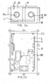
- the L-profile (see FIGS 6a, 6b and 6c) has, for example, the dimensions 100mm ⁇ 150mm ⁇ 30mm ⁇ 3mm (width ⁇ length ⁇ height ⁇ thickness).
- Cooling / support ribs R on both the top of the housing and the bottom of the housing enlarge the surface and thus improve both the Heat dissipation as well as the stability.
- a wedge or trapezoidal training the ribs R which are about 7mm high, reduces the surface, However, the formation of turbulence is reduced, resulting in the Heat radiation improved again.
- domes DO can the module / PCB L by means of self-tapping Fasten screws, while maintaining a sufficient distance between Printed circuit board L and housing lower part B is guaranteed.
- the lower housing part B may be electrically conductively coated from the inside.
- the area under the assembly / circuit board L is recessed to Prevent short circuits.
- the shield under the circuit board L is through the injected heat sink K realized.
- the housing upper part D several holes BO provided in which a sheet for electromagnetic shield attached with self-tapping screws can be.
- the holes in the upper and lower part D, B are designed so that only one type of screw is required.
- the printed circuit board L (see FIG. 5a and FIG. 5b) has, for example, the dimensions 100mm x 170mm x 1.6mm (Width ⁇ length ⁇ thickness).
- the components / components BE have on the top a maximum height of about 48mm, on the bottom about 2.5min.
- the Fixing the circuit board L is done by means of several screws in the housing. For this there are holes (about 3mm diameter) in the corners of the PCB. Self-tapping screws can be used.
- a web S is incorporated circumferentially inside.
- This Bridge S adjusts the housing upper part D during installation on the lower housing part B, so that it can not slip. This simplifies the assembly and ensures a good tightness when fitting accuracy.
- the cables are metric cable glands KV, for example M20 x 1.5, led into the housing.
- KV metric cable glands
- two on the two narrow sides Provide holes that have a corresponding thread.
- the two Holes on the right are optional and are usually closed, but can easily break out when needed.
- KV sealing rings can be used for the screw connection to achieve the required tightness. Also the used seals must be resistant to the above-mentioned pollutants.
- the two housing parts B, D are with several example self-tapping screws (about 4mm thread diameter) together connect.
- the housing upper part D is in each corner a fastening eye B ⁇ incorporated.
- the housing B, D can thus lying or in any position be installed hanging.
- the housing according to the invention ensures a simple, functional, cost-saving and thus optimal usability and thus reduced quite considerably the production costs.
- the heat sink K is directly in the Plastic cast the housing part B, which in each case in proportion optimized to each other a good heat transfer from the heat sink K in the Housing B, D, a good heat transfer and a good heat radiation
- Other advantages are: the electrical insulation between Heat sink K and components / components BE; the easy to install Attaching the semiconductor BE on the heat sink K by means of clips, which no Screwing is necessary and realized an additional cooling capacity of the clips is; the integration of the hold-down N in the upper housing part D, whereby prevents the clips to attach the semiconductor BE on Loosen heat sink K, for example by vibration; the derivative of Overvoltages (lightning protection) through the earthing through screw E in Housing upper part D; the larger area causes a greater cooling capacity the trapezoidal outer surface / ribs R of the housing B, D.
- the heat sink K at the production directly into the housing lower part B or into the housing upper part D. is injected.
- the heat sink K on nubs as a spacer placed on the tool and tolerance variations of the aluminum go directly into the wall thickness of the housing when the slider is the angle K during the injection process (i.e. ) Compensated.
- the knobs on the tool can have any shape, for example triangular, have circular etc. and size and density of the distribution, wherein the Weakening of stability by the heat sink K and by the profiled Plastic housing B, D is more than compensated.
- the inventive solid, heat dissipating and radiating Plastic housing with cooling / support ribs' and partially overmoulded, ins Housing interior protruding heat sink is used wherever high Claims of sealing ability, robustness (including against Environmental influences) and a maximum of efficient heat dissipation be used, for example in the automotive industry, shipbuilding, container construction, Caravanning, facade construction, silo technology, refrigeration and air conditioning technology and Device construction for telecommunication technology and industrial electronics.
- the plugs can be screwed directly into the housing (B and / or D), wherein also this connection and the plug itself are waterproof;
- the Assembly / module / circuit board L may be potted to be less susceptible to be against environmental influences, but here, the heat dissipation not is impaired;
- It can be provided locking elements with which for example, the printed circuit board L in the housing (preferably in B) is attached by clamping; it can still be undercuts or other Locking elements are provided on the housing lower part B, for example then hold the housing top D; to improve the tightness on Housing base B the support surface (bent edge) widened and in a groove for another seal are provided, etc.
Landscapes
- Engineering & Computer Science (AREA)
- Microelectronics & Electronic Packaging (AREA)
- Physics & Mathematics (AREA)
- Thermal Sciences (AREA)
- Cooling Or The Like Of Electrical Apparatus (AREA)
Applications Claiming Priority (2)
| Application Number | Priority Date | Filing Date | Title |
|---|---|---|---|
| DE2002147828 DE10247828B4 (de) | 2002-10-14 | 2002-10-14 | Wärmeableitendes und -abstrahlendes Kuststoffgehäuse mit Kühl-/Tragrippen und umpritztem Kühlkörper und Verfahren zu dessen Fertigung |
| DE10247828 | 2002-10-14 |
Publications (3)
| Publication Number | Publication Date |
|---|---|
| EP1422983A2 true EP1422983A2 (fr) | 2004-05-26 |
| EP1422983A3 EP1422983A3 (fr) | 2005-06-15 |
| EP1422983B1 EP1422983B1 (fr) | 2018-07-18 |
Family
ID=32086890
Family Applications (1)
| Application Number | Title | Priority Date | Filing Date |
|---|---|---|---|
| EP03023036.1A Expired - Lifetime EP1422983B1 (fr) | 2002-10-14 | 2003-10-13 | Boîtier plastique résistant à l'usure, conduisant et rayonnant la chaleur, pourvu de nervures de renfort et d'un radiateur surmoulé pour le refroidissement, procédé de fabrication de ce boîtier |
Country Status (3)
| Country | Link |
|---|---|
| EP (1) | EP1422983B1 (fr) |
| DE (1) | DE10247828B4 (fr) |
| ES (1) | ES2690771T3 (fr) |
Cited By (7)
| Publication number | Priority date | Publication date | Assignee | Title |
|---|---|---|---|---|
| EP1772877A1 (fr) * | 2005-06-02 | 2007-04-11 | STS Spezial-Transformatoren-Stockach GmbH & Co. KG | Transformateur MF avec meilleure dissipation thermique |
| EP2194768A1 (fr) * | 2008-12-04 | 2010-06-09 | Stribel Production GmbH | Dispositif d'emmagasinage d'énergie |
| EP2433478B1 (fr) * | 2009-05-20 | 2013-06-26 | Robert Bosch GmbH | Boîtier ou partie de boîtier pour un appareil de commande d'un véhicule automobile |
| EP2849311A1 (fr) * | 2013-09-16 | 2015-03-18 | Robert Bosch Gmbh | Chargeur de batterie |
| EP2849310A1 (fr) * | 2013-09-16 | 2015-03-18 | Robert Bosch Gmbh | Chargeur de batterie |
| DE102018215876A1 (de) * | 2018-09-18 | 2020-03-19 | Bayerische Motoren Werke Aktiengesellschaft | Steuereinrichtung für ein Kraftfahrzeug und Kraftfahrzeug mit einer solchen Steuereinrichtung |
| WO2022078689A1 (fr) * | 2020-10-14 | 2022-04-21 | Bayerische Motoren Werke Aktiengesellschaft | Support pour un dispositif de commande d'un véhicule et véhicule |
Families Citing this family (11)
| Publication number | Priority date | Publication date | Assignee | Title |
|---|---|---|---|---|
| DE102005043055B3 (de) * | 2005-09-09 | 2006-12-21 | Siemens Ag | Verfahren zur Herstellung eines Kühlkörpers mit Kühlrippen für ein Elektronikgehäuse |
| DE102007057533B4 (de) * | 2007-11-29 | 2016-07-07 | Fraunhofer-Gesellschaft zur Förderung der angewandten Forschung e.V. | Kühlkörper, Verfahren zur Herstellung eines Kühlkörpers und Leiterplatte mit Kühlkörper |
| DE102012207675A1 (de) | 2012-05-09 | 2013-11-14 | Robert Bosch Gmbh | Anordnung zur Wärmeableitung für ein Kunststoffgehäuse mit darin angeordneten elektronischen Bauelementen |
| EP2827687B1 (fr) | 2013-07-15 | 2019-03-13 | OSRAM GmbH | Procédé de fabrication d'une structure de support pour dispositifs d'éclairage |
| DE102014211443A1 (de) * | 2014-06-16 | 2015-12-17 | Robert Bosch Gmbh | Steuergerät mit wärmeleitfähiger Gehäusewand |
| DE102014211438A1 (de) * | 2014-06-16 | 2015-12-17 | Robert Bosch Gmbh | Steuergerät mit wärmeleitfähiger Gehäusewand |
| DE102016122601A1 (de) * | 2016-11-23 | 2018-05-24 | Atlas Elektronik Gmbh | Unterwasserfahrzeug mit Druckbehälter |
| DE102016122597A1 (de) * | 2016-11-23 | 2018-05-24 | Atlas Elektronik Gmbh | Unterwasserfahrzeug mit Druckbehälter |
| DE102017202431B3 (de) | 2017-02-15 | 2018-07-05 | Robert Bosch Gmbh | Steuergerät mit einem Kühlrippen aufweisenden Gehäuse und Verfahren zum Verschließen eines Gehäuses |
| WO2019061088A1 (fr) * | 2017-09-27 | 2019-04-04 | Changzhou Globe Co., Ltd. | Plaque pour le refroidissement d'un outil électrique |
| DE202021104219U1 (de) | 2021-08-06 | 2022-11-10 | Phoenix Contact Gmbh & Co. Kg | Elektronikgehäuse zur Montage an einer Tragschiene sowie ein System |
Citations (4)
| Publication number | Priority date | Publication date | Assignee | Title |
|---|---|---|---|---|
| DE3933123A1 (de) * | 1989-10-04 | 1991-04-11 | Bosch Gmbh Robert | Gehaeuse fuer eine elektronische schaltung |
| GB2256531A (en) * | 1991-05-28 | 1992-12-09 | Greenfields Europ Limited | Heatsinking of electrical fittings |
| EP0757384A2 (fr) * | 1995-07-31 | 1997-02-05 | Borg-Warner Automotive, Inc. | Méthode et appareil pour la dissipation de chaleur de semi-conducteurs |
| DE10014457A1 (de) * | 2000-03-23 | 2001-10-04 | Ulrich Grauvogel | Kühlkörper mit einem Gehäuse für eine wärmeabgebende elektronische Schaltung |
Family Cites Families (13)
| Publication number | Priority date | Publication date | Assignee | Title |
|---|---|---|---|---|
| DE2511010A1 (de) * | 1975-03-13 | 1976-09-23 | Bosch Gmbh Robert | Elektrisches bauelement mit kuehlkoerper |
| DE8704499U1 (de) * | 1987-03-26 | 1987-08-13 | Licentia Patent-Verwaltungs-Gmbh, 6000 Frankfurt | Elektrische Baueinheit |
| DE8812158U1 (de) * | 1988-09-26 | 1988-12-22 | Siemens AG, 1000 Berlin und 8000 München | Kühlvorrichtung für Transistoren |
| DE8815604U1 (de) * | 1988-12-15 | 1989-02-02 | Kobald Electronic Geräte GmbH, Wien | Kleingerätegehäuse für Tragschienenschnappmontage |
| DE3916899C2 (de) * | 1989-05-24 | 2003-04-03 | Bosch Gmbh Robert | Gehäuse zur Aufnahme einer elektronischen Schaltung |
| DE19533298A1 (de) * | 1995-09-08 | 1997-03-13 | Siemens Ag | Elektronisches Modul mit Leistungsbauelementen |
| JP3923111B2 (ja) * | 1996-10-31 | 2007-05-30 | 古河電気工業株式会社 | 電気接続箱 |
| DE19855389C2 (de) * | 1998-12-01 | 2002-10-31 | Siemens Ag | Elektronische Vorrichtung |
| DE19857840C2 (de) * | 1998-12-15 | 2003-10-02 | Siemens Ag | Elektronische Einrichtung |
| DE19929209A1 (de) * | 1999-06-25 | 2001-01-18 | Siemens Ag | Elektronisches Steuergerät mit Kühlkörper und Herstellungsverfahren |
| DE19953191A1 (de) * | 1999-11-05 | 2001-05-10 | Bosch Gmbh Robert | Elektronisches Steuergerät |
| DE10013844A1 (de) * | 2000-03-15 | 2001-09-27 | Infineon Technologies Ag | Vorrichtung zum Kühlen eines elektrischen Moduls |
| DE10065857B4 (de) * | 2000-12-22 | 2005-04-14 | Siemens Ag | Wärmeübertragungsanordnung für ein Kuststoffgehäuse elektronischer Baugruppen |
-
2002
- 2002-10-14 DE DE2002147828 patent/DE10247828B4/de not_active Expired - Lifetime
-
2003
- 2003-10-13 EP EP03023036.1A patent/EP1422983B1/fr not_active Expired - Lifetime
- 2003-10-13 ES ES03023036.1T patent/ES2690771T3/es not_active Expired - Lifetime
Patent Citations (4)
| Publication number | Priority date | Publication date | Assignee | Title |
|---|---|---|---|---|
| DE3933123A1 (de) * | 1989-10-04 | 1991-04-11 | Bosch Gmbh Robert | Gehaeuse fuer eine elektronische schaltung |
| GB2256531A (en) * | 1991-05-28 | 1992-12-09 | Greenfields Europ Limited | Heatsinking of electrical fittings |
| EP0757384A2 (fr) * | 1995-07-31 | 1997-02-05 | Borg-Warner Automotive, Inc. | Méthode et appareil pour la dissipation de chaleur de semi-conducteurs |
| DE10014457A1 (de) * | 2000-03-23 | 2001-10-04 | Ulrich Grauvogel | Kühlkörper mit einem Gehäuse für eine wärmeabgebende elektronische Schaltung |
Cited By (14)
| Publication number | Priority date | Publication date | Assignee | Title |
|---|---|---|---|---|
| EP1772877A1 (fr) * | 2005-06-02 | 2007-04-11 | STS Spezial-Transformatoren-Stockach GmbH & Co. KG | Transformateur MF avec meilleure dissipation thermique |
| EP2194768A1 (fr) * | 2008-12-04 | 2010-06-09 | Stribel Production GmbH | Dispositif d'emmagasinage d'énergie |
| US8780566B2 (en) | 2008-12-04 | 2014-07-15 | Flextronics International Kft. | Energy storage device with gas-tight capacitor chamber |
| EP2433478B1 (fr) * | 2009-05-20 | 2013-06-26 | Robert Bosch GmbH | Boîtier ou partie de boîtier pour un appareil de commande d'un véhicule automobile |
| CN104467070A (zh) * | 2013-09-16 | 2015-03-25 | 罗伯特·博世有限公司 | 蓄电池充电装置和包括蓄电池充电装置的系统 |
| EP2849310A1 (fr) * | 2013-09-16 | 2015-03-18 | Robert Bosch Gmbh | Chargeur de batterie |
| EP2849311A1 (fr) * | 2013-09-16 | 2015-03-18 | Robert Bosch Gmbh | Chargeur de batterie |
| CN104467069A (zh) * | 2013-09-16 | 2015-03-25 | 罗伯特·博世有限公司 | 蓄电池充电装置和包括蓄电池充电装置的系统 |
| US10601236B2 (en) | 2013-09-16 | 2020-03-24 | Robert Bosch Gmbh | Battery charging device |
| US10630088B2 (en) | 2013-09-16 | 2020-04-21 | Robert Bosch Gmbh | Battery charging device |
| CN104467069B (zh) * | 2013-09-16 | 2020-10-02 | 罗伯特·博世有限公司 | 蓄电池充电装置和包括蓄电池充电装置的系统 |
| CN104467070B (zh) * | 2013-09-16 | 2020-10-02 | 罗伯特·博世有限公司 | 蓄电池充电装置和包括蓄电池充电装置的系统 |
| DE102018215876A1 (de) * | 2018-09-18 | 2020-03-19 | Bayerische Motoren Werke Aktiengesellschaft | Steuereinrichtung für ein Kraftfahrzeug und Kraftfahrzeug mit einer solchen Steuereinrichtung |
| WO2022078689A1 (fr) * | 2020-10-14 | 2022-04-21 | Bayerische Motoren Werke Aktiengesellschaft | Support pour un dispositif de commande d'un véhicule et véhicule |
Also Published As
| Publication number | Publication date |
|---|---|
| ES2690771T3 (es) | 2018-11-22 |
| EP1422983A3 (fr) | 2005-06-15 |
| EP1422983B1 (fr) | 2018-07-18 |
| DE10247828A1 (de) | 2004-05-06 |
| DE10247828B4 (de) | 2005-03-03 |
Similar Documents
| Publication | Publication Date | Title |
|---|---|---|
| EP1422983B1 (fr) | Boîtier plastique résistant à l'usure, conduisant et rayonnant la chaleur, pourvu de nervures de renfort et d'un radiateur surmoulé pour le refroidissement, procédé de fabrication de ce boîtier | |
| DE2825582C2 (de) | Kühlvorrichtung für Halbleiterelemente | |
| DE112015003987B4 (de) | Schaltungsbaugruppe, elektrischer Verteiler und Herstellungsverfahren für eine Schaltungsbaugruppe | |
| EP2439774B1 (fr) | Dissipateur de chaleur doté d'un tuyau de chauffage stocké de manière flexible | |
| EP1395098B1 (fr) | Chauffage électrique pour véhicule | |
| DE102005037488B4 (de) | Kühlanordnung und deren Verwendung sowie Kompaktantrieb und Umrichter mit einer derartigen Kühlanordnung | |
| DE102007057533B4 (de) | Kühlkörper, Verfahren zur Herstellung eines Kühlkörpers und Leiterplatte mit Kühlkörper | |
| EP2327286B1 (fr) | Boîtier de circuit avec élément de couplage thermique | |
| DE102012001917A1 (de) | Elektrisches Gerät | |
| DE112015005727T5 (de) | Schaltungsanordnung und elektrischer Verteiler | |
| DE102015103096A1 (de) | Kühleinrichtung und Kühlanordnung mit der Kühleinrichtung | |
| DE2722142B2 (de) | Metallische Gehäusewandung für ein elektronische Bauelemente aufnehmendes Gehäuse | |
| DE102011009768A1 (de) | Halten einer Mehrzahl von elektrischen Energiespeicherzellen | |
| EP2222150B1 (fr) | Plaquette dotée d'un corps de refroidissement | |
| EP2317618A2 (fr) | Appareil d'installation électrique doté d'au moins un composant électrique émettant de la chaleur | |
| EP3841854B1 (fr) | Procédé permettant un montage d'un appareil électrique | |
| DE10300175B4 (de) | Elektronische Baugruppe mit Wärme ableitendem Gehäuseteil | |
| DE19904279B4 (de) | Halbleitervorrichtung | |
| DE102011010431A1 (de) | Elektrisches Gerät | |
| DE112015004241B4 (de) | Elektrischer Verteiler | |
| DE102017128928B4 (de) | Elektronikbaueinheit | |
| DE102018222748B4 (de) | Kühlvorrichtung | |
| DE102014004798B4 (de) | Elektrisches Gerät | |
| DE102020117366A1 (de) | Elektrische Steuervorrichtung, insbesondere für eine elektrische Heizvorrichtung | |
| DE10306130A1 (de) | Geschirmte und gekühlte elektronische Baugruppe |
Legal Events
| Date | Code | Title | Description |
|---|---|---|---|
| PUAI | Public reference made under article 153(3) epc to a published international application that has entered the european phase |
Free format text: ORIGINAL CODE: 0009012 |
|
| AK | Designated contracting states |
Kind code of ref document: A2 Designated state(s): AT BE BG CH CY CZ DE DK EE ES FI FR GB GR HU IE IT LI LU MC NL PT RO SE SI SK TR |
|
| AX | Request for extension of the european patent |
Extension state: AL LT LV MK |
|
| PUAL | Search report despatched |
Free format text: ORIGINAL CODE: 0009013 |
|
| AK | Designated contracting states |
Kind code of ref document: A3 Designated state(s): AT BE BG CH CY CZ DE DK EE ES FI FR GB GR HU IE IT LI LU MC NL PT RO SE SI SK TR |
|
| AX | Request for extension of the european patent |
Extension state: AL LT LV MK |
|
| 17P | Request for examination filed |
Effective date: 20051209 |
|
| AKX | Designation fees paid |
Designated state(s): AT BE BG CH CY CZ DE DK EE ES FI FR GB GR HU IE IT LI LU MC NL PT RO SE SI SK TR |
|
| RAP1 | Party data changed (applicant data changed or rights of an application transferred) |
Owner name: IAD GESELLSCHAFT FUER INFORMATIK, AUTOMATISIERUNG |
|
| 17Q | First examination report despatched |
Effective date: 20160628 |
|
| GRAP | Despatch of communication of intention to grant a patent |
Free format text: ORIGINAL CODE: EPIDOSNIGR1 |
|
| INTG | Intention to grant announced |
Effective date: 20180220 |
|
| GRAS | Grant fee paid |
Free format text: ORIGINAL CODE: EPIDOSNIGR3 |
|
| GRAA | (expected) grant |
Free format text: ORIGINAL CODE: 0009210 |
|
| AK | Designated contracting states |
Kind code of ref document: B1 Designated state(s): AT BE BG CH CY CZ DE DK EE ES FI FR GB GR HU IE IT LI LU MC NL PT RO SE SI SK TR |
|
| REG | Reference to a national code |
Ref country code: GB Ref legal event code: FG4D Free format text: NOT ENGLISH |
|
| REG | Reference to a national code |
Ref country code: CH Ref legal event code: EP |
|
| REG | Reference to a national code |
Ref country code: IE Ref legal event code: FG4D Free format text: LANGUAGE OF EP DOCUMENT: GERMAN |
|
| REG | Reference to a national code |
Ref country code: AT Ref legal event code: REF Ref document number: 1020766 Country of ref document: AT Kind code of ref document: T Effective date: 20180815 |
|
| REG | Reference to a national code |
Ref country code: DE Ref legal event code: R096 Ref document number: 50315765 Country of ref document: DE |
|
| REG | Reference to a national code |
Ref country code: NL Ref legal event code: MP Effective date: 20180718 |
|
| REG | Reference to a national code |
Ref country code: ES Ref legal event code: FG2A Ref document number: 2690771 Country of ref document: ES Kind code of ref document: T3 Effective date: 20181122 |
|
| PG25 | Lapsed in a contracting state [announced via postgrant information from national office to epo] |
Ref country code: NL Free format text: LAPSE BECAUSE OF FAILURE TO SUBMIT A TRANSLATION OF THE DESCRIPTION OR TO PAY THE FEE WITHIN THE PRESCRIBED TIME-LIMIT Effective date: 20180718 |
|
| PG25 | Lapsed in a contracting state [announced via postgrant information from national office to epo] |
Ref country code: SE Free format text: LAPSE BECAUSE OF FAILURE TO SUBMIT A TRANSLATION OF THE DESCRIPTION OR TO PAY THE FEE WITHIN THE PRESCRIBED TIME-LIMIT Effective date: 20180718 Ref country code: BG Free format text: LAPSE BECAUSE OF FAILURE TO SUBMIT A TRANSLATION OF THE DESCRIPTION OR TO PAY THE FEE WITHIN THE PRESCRIBED TIME-LIMIT Effective date: 20181018 Ref country code: FI Free format text: LAPSE BECAUSE OF FAILURE TO SUBMIT A TRANSLATION OF THE DESCRIPTION OR TO PAY THE FEE WITHIN THE PRESCRIBED TIME-LIMIT Effective date: 20180718 Ref country code: GR Free format text: LAPSE BECAUSE OF FAILURE TO SUBMIT A TRANSLATION OF THE DESCRIPTION OR TO PAY THE FEE WITHIN THE PRESCRIBED TIME-LIMIT Effective date: 20181019 |
|
| REG | Reference to a national code |
Ref country code: CH Ref legal event code: PK Free format text: BERICHTIGUNGEN |
|
| RIC2 | Information provided on ipc code assigned after grant |
Ipc: H05K 7/20 20060101AFI20040406BHEP |
|
| REG | Reference to a national code |
Ref country code: DE Ref legal event code: R097 Ref document number: 50315765 Country of ref document: DE |
|
| PG25 | Lapsed in a contracting state [announced via postgrant information from national office to epo] |
Ref country code: EE Free format text: LAPSE BECAUSE OF FAILURE TO SUBMIT A TRANSLATION OF THE DESCRIPTION OR TO PAY THE FEE WITHIN THE PRESCRIBED TIME-LIMIT Effective date: 20180718 Ref country code: CZ Free format text: LAPSE BECAUSE OF FAILURE TO SUBMIT A TRANSLATION OF THE DESCRIPTION OR TO PAY THE FEE WITHIN THE PRESCRIBED TIME-LIMIT Effective date: 20180718 Ref country code: RO Free format text: LAPSE BECAUSE OF FAILURE TO SUBMIT A TRANSLATION OF THE DESCRIPTION OR TO PAY THE FEE WITHIN THE PRESCRIBED TIME-LIMIT Effective date: 20180718 |
|
| PLBE | No opposition filed within time limit |
Free format text: ORIGINAL CODE: 0009261 |
|
| STAA | Information on the status of an ep patent application or granted ep patent |
Free format text: STATUS: NO OPPOSITION FILED WITHIN TIME LIMIT |
|
| PG25 | Lapsed in a contracting state [announced via postgrant information from national office to epo] |
Ref country code: SK Free format text: LAPSE BECAUSE OF FAILURE TO SUBMIT A TRANSLATION OF THE DESCRIPTION OR TO PAY THE FEE WITHIN THE PRESCRIBED TIME-LIMIT Effective date: 20180718 Ref country code: DK Free format text: LAPSE BECAUSE OF FAILURE TO SUBMIT A TRANSLATION OF THE DESCRIPTION OR TO PAY THE FEE WITHIN THE PRESCRIBED TIME-LIMIT Effective date: 20180718 |
|
| REG | Reference to a national code |
Ref country code: CH Ref legal event code: PL |
|
| 26N | No opposition filed |
Effective date: 20190423 |
|
| PG25 | Lapsed in a contracting state [announced via postgrant information from national office to epo] |
Ref country code: MC Free format text: LAPSE BECAUSE OF FAILURE TO SUBMIT A TRANSLATION OF THE DESCRIPTION OR TO PAY THE FEE WITHIN THE PRESCRIBED TIME-LIMIT Effective date: 20180718 Ref country code: LU Free format text: LAPSE BECAUSE OF NON-PAYMENT OF DUE FEES Effective date: 20181013 |
|
| REG | Reference to a national code |
Ref country code: IE Ref legal event code: MM4A |
|
| PG25 | Lapsed in a contracting state [announced via postgrant information from national office to epo] |
Ref country code: LI Free format text: LAPSE BECAUSE OF NON-PAYMENT OF DUE FEES Effective date: 20181031 Ref country code: CH Free format text: LAPSE BECAUSE OF NON-PAYMENT OF DUE FEES Effective date: 20181031 Ref country code: SI Free format text: LAPSE BECAUSE OF FAILURE TO SUBMIT A TRANSLATION OF THE DESCRIPTION OR TO PAY THE FEE WITHIN THE PRESCRIBED TIME-LIMIT Effective date: 20180718 |
|
| PG25 | Lapsed in a contracting state [announced via postgrant information from national office to epo] |
Ref country code: IE Free format text: LAPSE BECAUSE OF NON-PAYMENT OF DUE FEES Effective date: 20181013 |
|
| PG25 | Lapsed in a contracting state [announced via postgrant information from national office to epo] |
Ref country code: TR Free format text: LAPSE BECAUSE OF FAILURE TO SUBMIT A TRANSLATION OF THE DESCRIPTION OR TO PAY THE FEE WITHIN THE PRESCRIBED TIME-LIMIT Effective date: 20180718 |
|
| PG25 | Lapsed in a contracting state [announced via postgrant information from national office to epo] |
Ref country code: PT Free format text: LAPSE BECAUSE OF FAILURE TO SUBMIT A TRANSLATION OF THE DESCRIPTION OR TO PAY THE FEE WITHIN THE PRESCRIBED TIME-LIMIT Effective date: 20180718 |
|
| PG25 | Lapsed in a contracting state [announced via postgrant information from national office to epo] |
Ref country code: CY Free format text: LAPSE BECAUSE OF FAILURE TO SUBMIT A TRANSLATION OF THE DESCRIPTION OR TO PAY THE FEE WITHIN THE PRESCRIBED TIME-LIMIT Effective date: 20180718 Ref country code: HU Free format text: LAPSE BECAUSE OF FAILURE TO SUBMIT A TRANSLATION OF THE DESCRIPTION OR TO PAY THE FEE WITHIN THE PRESCRIBED TIME-LIMIT; INVALID AB INITIO Effective date: 20031013 |
|
| REG | Reference to a national code |
Ref country code: ES Ref legal event code: FD2A Effective date: 20220121 |
|
| PGFP | Annual fee paid to national office [announced via postgrant information from national office to epo] |
Ref country code: FR Payment date: 20221024 Year of fee payment: 20 |
|
| PGFP | Annual fee paid to national office [announced via postgrant information from national office to epo] |
Ref country code: IT Payment date: 20221011 Year of fee payment: 20 Ref country code: GB Payment date: 20221013 Year of fee payment: 20 Ref country code: ES Payment date: 20221123 Year of fee payment: 20 Ref country code: DE Payment date: 20221011 Year of fee payment: 20 Ref country code: AT Payment date: 20221011 Year of fee payment: 20 |
|
| PGFP | Annual fee paid to national office [announced via postgrant information from national office to epo] |
Ref country code: BE Payment date: 20221011 Year of fee payment: 20 |
|
| REG | Reference to a national code |
Ref country code: DE Ref legal event code: R071 Ref document number: 50315765 Country of ref document: DE |
|
| REG | Reference to a national code |
Ref country code: BE Ref legal event code: MK Effective date: 20231013 |
|
| REG | Reference to a national code |
Ref country code: ES Ref legal event code: FD2A Effective date: 20231026 |
|
| REG | Reference to a national code |
Ref country code: GB Ref legal event code: PE20 Expiry date: 20231012 |
|
| REG | Reference to a national code |
Ref country code: AT Ref legal event code: MK07 Ref document number: 1020766 Country of ref document: AT Kind code of ref document: T Effective date: 20231013 |
|
| PG25 | Lapsed in a contracting state [announced via postgrant information from national office to epo] |
Ref country code: GB Free format text: LAPSE BECAUSE OF EXPIRATION OF PROTECTION Effective date: 20231012 |
|
| PG25 | Lapsed in a contracting state [announced via postgrant information from national office to epo] |
Ref country code: ES Free format text: LAPSE BECAUSE OF EXPIRATION OF PROTECTION Effective date: 20231014 |
|
| PG25 | Lapsed in a contracting state [announced via postgrant information from national office to epo] |
Ref country code: GB Free format text: LAPSE BECAUSE OF EXPIRATION OF PROTECTION Effective date: 20231012 Ref country code: ES Free format text: LAPSE BECAUSE OF EXPIRATION OF PROTECTION Effective date: 20231014 |