EP1422983A2 - Wear resistant , heat conductive , heat radiating , plastic housing provided with supporting fins and overmolded heat sink for cooling, method of manufacturing the same - Google Patents
Wear resistant , heat conductive , heat radiating , plastic housing provided with supporting fins and overmolded heat sink for cooling, method of manufacturing the same Download PDFInfo
- Publication number
- EP1422983A2 EP1422983A2 EP03023036A EP03023036A EP1422983A2 EP 1422983 A2 EP1422983 A2 EP 1422983A2 EP 03023036 A EP03023036 A EP 03023036A EP 03023036 A EP03023036 A EP 03023036A EP 1422983 A2 EP1422983 A2 EP 1422983A2
- Authority
- EP
- European Patent Office
- Prior art keywords
- housing
- heat
- heat sink
- plastic
- cooling
- Prior art date
- Legal status (The legal status is an assumption and is not a legal conclusion. Google has not performed a legal analysis and makes no representation as to the accuracy of the status listed.)
- Granted
Links
- 239000004033 plastic Substances 0.000 title claims abstract description 77
- 229920003023 plastic Polymers 0.000 title claims abstract description 77
- 238000001816 cooling Methods 0.000 title claims abstract description 29
- 238000004519 manufacturing process Methods 0.000 title claims description 18
- 238000012546 transfer Methods 0.000 claims description 34
- 239000004020 conductor Substances 0.000 claims description 10
- 238000000034 method Methods 0.000 claims description 6
- 238000001125 extrusion Methods 0.000 claims description 3
- 210000004907 gland Anatomy 0.000 claims description 3
- 230000008569 process Effects 0.000 claims description 3
- 125000006850 spacer group Chemical group 0.000 claims description 3
- 238000001746 injection moulding Methods 0.000 abstract description 6
- 230000017525 heat dissipation Effects 0.000 description 33
- 229910052751 metal Inorganic materials 0.000 description 16
- 239000002184 metal Substances 0.000 description 16
- 230000005855 radiation Effects 0.000 description 16
- 229910052782 aluminium Inorganic materials 0.000 description 15
- XAGFODPZIPBFFR-UHFFFAOYSA-N aluminium Chemical compound [Al] XAGFODPZIPBFFR-UHFFFAOYSA-N 0.000 description 15
- 230000007613 environmental effect Effects 0.000 description 11
- 230000008901 benefit Effects 0.000 description 9
- 150000001875 compounds Chemical class 0.000 description 7
- 230000001681 protective effect Effects 0.000 description 7
- 239000000758 substrate Substances 0.000 description 7
- XLYOFNOQVPJJNP-UHFFFAOYSA-N water Chemical compound O XLYOFNOQVPJJNP-UHFFFAOYSA-N 0.000 description 7
- 238000010521 absorption reaction Methods 0.000 description 6
- 238000005266 casting Methods 0.000 description 6
- 238000013461 design Methods 0.000 description 6
- 238000009434 installation Methods 0.000 description 6
- RYGMFSIKBFXOCR-UHFFFAOYSA-N Copper Chemical compound [Cu] RYGMFSIKBFXOCR-UHFFFAOYSA-N 0.000 description 5
- 239000003990 capacitor Substances 0.000 description 5
- 238000010276 construction Methods 0.000 description 5
- 229910052802 copper Inorganic materials 0.000 description 5
- 239000010949 copper Substances 0.000 description 5
- 238000005516 engineering process Methods 0.000 description 5
- 239000004065 semiconductor Substances 0.000 description 5
- 238000010292 electrical insulation Methods 0.000 description 4
- 239000003344 environmental pollutant Substances 0.000 description 4
- 231100000719 pollutant Toxicity 0.000 description 4
- 238000010079 rubber tapping Methods 0.000 description 4
- 238000007789 sealing Methods 0.000 description 4
- 229920000049 Carbon (fiber) Polymers 0.000 description 3
- 238000009825 accumulation Methods 0.000 description 3
- 239000004917 carbon fiber Substances 0.000 description 3
- 239000000919 ceramic Substances 0.000 description 3
- 239000000446 fuel Substances 0.000 description 3
- 239000008187 granular material Substances 0.000 description 3
- 230000006872 improvement Effects 0.000 description 3
- 238000002347 injection Methods 0.000 description 3
- 239000007924 injection Substances 0.000 description 3
- 239000000463 material Substances 0.000 description 3
- 238000000465 moulding Methods 0.000 description 3
- 239000000243 solution Substances 0.000 description 3
- 238000012549 training Methods 0.000 description 3
- 239000000853 adhesive Substances 0.000 description 2
- 230000001070 adhesive effect Effects 0.000 description 2
- 239000003570 air Substances 0.000 description 2
- 230000008878 coupling Effects 0.000 description 2
- 238000010168 coupling process Methods 0.000 description 2
- 238000005859 coupling reaction Methods 0.000 description 2
- 238000011161 development Methods 0.000 description 2
- 230000009977 dual effect Effects 0.000 description 2
- 238000005538 encapsulation Methods 0.000 description 2
- 239000000945 filler Substances 0.000 description 2
- 239000011440 grout Substances 0.000 description 2
- 150000002739 metals Chemical class 0.000 description 2
- 230000000704 physical effect Effects 0.000 description 2
- 239000000843 powder Substances 0.000 description 2
- 239000000565 sealant Substances 0.000 description 2
- FRWYFWZENXDZMU-UHFFFAOYSA-N 2-iodoquinoline Chemical compound C1=CC=CC2=NC(I)=CC=C21 FRWYFWZENXDZMU-UHFFFAOYSA-N 0.000 description 1
- 229910000881 Cu alloy Inorganic materials 0.000 description 1
- XEEYBQQBJWHFJM-UHFFFAOYSA-N Iron Chemical compound [Fe] XEEYBQQBJWHFJM-UHFFFAOYSA-N 0.000 description 1
- FYYHWMGAXLPEAU-UHFFFAOYSA-N Magnesium Chemical compound [Mg] FYYHWMGAXLPEAU-UHFFFAOYSA-N 0.000 description 1
- BPQQTUXANYXVAA-UHFFFAOYSA-N Orthosilicate Chemical compound [O-][Si]([O-])([O-])[O-] BPQQTUXANYXVAA-UHFFFAOYSA-N 0.000 description 1
- 230000009471 action Effects 0.000 description 1
- 238000004378 air conditioning Methods 0.000 description 1
- 239000012080 ambient air Substances 0.000 description 1
- 238000013459 approach Methods 0.000 description 1
- LTPBRCUWZOMYOC-UHFFFAOYSA-N beryllium oxide Inorganic materials O=[Be] LTPBRCUWZOMYOC-UHFFFAOYSA-N 0.000 description 1
- 230000015572 biosynthetic process Effects 0.000 description 1
- 230000003139 buffering effect Effects 0.000 description 1
- 239000003795 chemical substances by application Substances 0.000 description 1
- PMHQVHHXPFUNSP-UHFFFAOYSA-M copper(1+);methylsulfanylmethane;bromide Chemical compound Br[Cu].CSC PMHQVHHXPFUNSP-UHFFFAOYSA-M 0.000 description 1
- 238000005260 corrosion Methods 0.000 description 1
- 230000007797 corrosion Effects 0.000 description 1
- 230000001419 dependent effect Effects 0.000 description 1
- 238000004512 die casting Methods 0.000 description 1
- 238000009826 distribution Methods 0.000 description 1
- 229920001971 elastomer Polymers 0.000 description 1
- 239000000806 elastomer Substances 0.000 description 1
- 239000012765 fibrous filler Substances 0.000 description 1
- 238000010304 firing Methods 0.000 description 1
- 239000011888 foil Substances 0.000 description 1
- 125000000524 functional group Chemical group 0.000 description 1
- 239000004519 grease Substances 0.000 description 1
- 238000010438 heat treatment Methods 0.000 description 1
- 230000001771 impaired effect Effects 0.000 description 1
- 238000009413 insulation Methods 0.000 description 1
- 230000010354 integration Effects 0.000 description 1
- 239000003350 kerosene Substances 0.000 description 1
- 229910052749 magnesium Inorganic materials 0.000 description 1
- 239000011777 magnesium Substances 0.000 description 1
- NJPPVKZQTLUDBO-UHFFFAOYSA-N novaluron Chemical compound C1=C(Cl)C(OC(F)(F)C(OC(F)(F)F)F)=CC=C1NC(=O)NC(=O)C1=C(F)C=CC=C1F NJPPVKZQTLUDBO-UHFFFAOYSA-N 0.000 description 1
- 238000005457 optimization Methods 0.000 description 1
- TWNQGVIAIRXVLR-UHFFFAOYSA-N oxo(oxoalumanyloxy)alumane Chemical compound O=[Al]O[Al]=O TWNQGVIAIRXVLR-UHFFFAOYSA-N 0.000 description 1
- 230000002093 peripheral effect Effects 0.000 description 1
- 229920001296 polysiloxane Polymers 0.000 description 1
- 230000002265 prevention Effects 0.000 description 1
- 238000004080 punching Methods 0.000 description 1
- 238000005057 refrigeration Methods 0.000 description 1
- 230000008439 repair process Effects 0.000 description 1
- 150000003839 salts Chemical class 0.000 description 1
- 239000013535 sea water Substances 0.000 description 1
- 238000000926 separation method Methods 0.000 description 1
- 239000002689 soil Substances 0.000 description 1
- 239000007787 solid Substances 0.000 description 1
- 239000010935 stainless steel Substances 0.000 description 1
- 229910001220 stainless steel Inorganic materials 0.000 description 1
- 238000010257 thawing Methods 0.000 description 1
- 229920001169 thermoplastic Polymers 0.000 description 1
- 239000004416 thermosoftening plastic Substances 0.000 description 1
- 230000007704 transition Effects 0.000 description 1
- 238000010792 warming Methods 0.000 description 1
- 230000003313 weakening effect Effects 0.000 description 1
- 238000003466 welding Methods 0.000 description 1
Images


Classifications
-
- H—ELECTRICITY
- H05—ELECTRIC TECHNIQUES NOT OTHERWISE PROVIDED FOR
- H05K—PRINTED CIRCUITS; CASINGS OR CONSTRUCTIONAL DETAILS OF ELECTRIC APPARATUS; MANUFACTURE OF ASSEMBLAGES OF ELECTRICAL COMPONENTS
- H05K5/00—Casings, cabinets or drawers for electric apparatus
- H05K5/06—Hermetically-sealed casings
- H05K5/066—Hermetically-sealed casings sealed by fusion of the joining parts without bringing material; sealed by brazing
-
- H—ELECTRICITY
- H05—ELECTRIC TECHNIQUES NOT OTHERWISE PROVIDED FOR
- H05K—PRINTED CIRCUITS; CASINGS OR CONSTRUCTIONAL DETAILS OF ELECTRIC APPARATUS; MANUFACTURE OF ASSEMBLAGES OF ELECTRICAL COMPONENTS
- H05K7/00—Constructional details common to different types of electric apparatus
- H05K7/20—Modifications to facilitate cooling, ventilating, or heating
- H05K7/2039—Modifications to facilitate cooling, ventilating, or heating characterised by the heat transfer by conduction from the heat generating element to a dissipating body
- H05K7/20509—Multiple-component heat spreaders; Multi-component heat-conducting support plates; Multi-component non-closed heat-conducting structures
-
- H—ELECTRICITY
- H05—ELECTRIC TECHNIQUES NOT OTHERWISE PROVIDED FOR
- H05K—PRINTED CIRCUITS; CASINGS OR CONSTRUCTIONAL DETAILS OF ELECTRIC APPARATUS; MANUFACTURE OF ASSEMBLAGES OF ELECTRICAL COMPONENTS
- H05K7/00—Constructional details common to different types of electric apparatus
- H05K7/20—Modifications to facilitate cooling, ventilating, or heating
- H05K7/20845—Modifications to facilitate cooling, ventilating, or heating for automotive electronic casings
- H05K7/20854—Heat transfer by conduction from internal heat source to heat radiating structure
Landscapes
- Engineering & Computer Science (AREA)
- Microelectronics & Electronic Packaging (AREA)
- Physics & Mathematics (AREA)
- Thermal Sciences (AREA)
- Cooling Or The Like Of Electrical Apparatus (AREA)
Abstract
Description
Die Erfindung betrifft in erster Linie ein Gehäuse, welches zwei Gehäuse-Kunststoffschalen und einen im Gehäuse angeordneten Kühlkörper aufweist (Patentanspruch 1). Weiterhin betrifft die Erfindung ein Verfahren zur Herstellung des Gehäuses nach Anspruch 1 (Patentanspruch 9).The invention relates in the first place to a housing which has two housing plastic shells and has a heat sink disposed in the housing (Claim 1). Furthermore, the invention relates to a method for Production of the housing according to claim 1 (claim 9).
Gehäuse für elektronische Schaltungen, die Umwelteinflüssen ausgesetzt sind, müssen dicht schließen. Bei der Auslegung des Gehäuses ist darauf zu achten, dass die von den Bauelementen, beispielsweise einer Leistungsstufe, erzeugte Verlustwärme in einem derartigen Maße abgeführt wird, dass keine unzulässige Erwärmung stattfindet.Housings for electronic circuits that are exposed to environmental influences must close tightly. When designing the housing, make sure that that generated by the components, for example a power stage Loss heat is dissipated to such an extent that no inadmissible Warming is taking place.
Um ein Gehäuse verfügbar zu machen, das bei kleinem kompakten Aufbau die Aufnahme von elektrischen und/oder elektronischen Schaltungen mit relativ hoher Verlustwärme ohne deren Gefährdung durch Wärmestau ermöglicht, ist beispielsweise aus dem G 88 15 604.4 ein Gehäuse mit einem Gehäuseboden bekannt, welcher wenigstens teilweise direkt als Kühlkörper mit einem Kühlprofil ausgebildet ist. Da die entstehende Wärme direkt nach außen abgeführt wird, bildet sich im Gehäuseinnern kein unerwünschter Wärmestau aus, der empfindliche Bauteile gefährden könnte. Der Kühlkörper besteht aus einem wärmeleitenden Material, vorzugsweise aus Aluminium. Der Gehäuseboden mit dem Kühlkörper sitzt direkt auf einer üblicherweise metallisch ausgebildeten Montage- bzw. Tragschiene auf, so dass nicht nur eine Wärmeableitung durch Konvektion über das Kühlprofil, sondern auch zusätzlich eine Wärmeableitung über die Tragschiene erfolgt. Um eine zusätzliche Verbesserung der Wärmeableitung vom Gehäuseinnern zu der Gehäusebodenaußenseite zu realisieren, weist der Gehäuseboden wenigstens im Bereich der Kühlprofilabschnitte Montagebohrungen auf, die für den Eingriff von ebenfalls gut wärmeleitenden Befestigungsmitteln, wie Schrauben oder dergleichen vorgesehen sind.To make a case available, which in a small compact design the Recording of electrical and / or electronic circuits with relative high heat loss is possible without their endangerment by heat accumulation is For example, from the G 88 15 604.4 a housing with a housing bottom known which at least partially directly as a heat sink with a Cooling profile is formed. Because the resulting heat directly to the outside is dissipated, forms inside the housing no unwanted heat accumulation which could endanger sensitive components. The heat sink consists of a thermally conductive material, preferably of aluminum. Of the Caseback with the heat sink sits directly on one usually metallic trained mounting or mounting rail, so that not only one Heat dissipation by convection through the cooling profile, but also In addition, a heat dissipation via the mounting rail takes place. To one additional improvement of Heat dissipation from the housing interior to the housing bottom outside realize, the housing bottom, at least in the area of Cooling section sections mounting holes on, for the engagement of likewise good heat-conducting fasteners, such as screws or the like are provided.
Ein ähnlicher Weg ist bei der aus der DE 100 13 844 A1 bekannten Vorrichtung zum Kühlen eines elektrischen Moduls eingeschlagen worden. Um die Wärmeabfuhr zur Kühlung von elektronischen oder elektrischen Bauteilen und ganzen Baugruppen/Modulen zu verbessern, ist auf dem/den Modul(en) ein aus Kunststoff gebildeter Kühlkörper befestigt, wobei zur Optimierung der physikalischen Eigenschaften des Kühlkörpers, insbesondere hinsichtlich der Wärmeleitfähigkeit und/oder des Wärmeausdehnungskoeffizienten, in den Kunststoff ein Füllstoff, beispielsweise Kohlenstofffasern und/oder ein Metallgranulat, eingelagert ist. Kohlenstofffasern besitzen Wärmeleitfähigkeiten, die größer als 1000 W/mK sein können. Im Vergleich dazu besitzen die Metalle, aus denen metallische Kühlkörper gebildet werden, wesentlich geringere Wärmeleitfähigkeiten. Die Wärmeleitfähigkeit für Aluminium beträgt beispielsweise ca. 200 W/mK. Für Kupfer und CuW 85/15 beträgt die Wärmeleitfähigkeit 380 W/mK bzw. 230 W/mK. Mit Hilfe der Abstimmung des Verhältnisses, beispielsweise hinsichtlich Gesamtmasse der eingelagerten Kohlenstofffasern und der Metallgranulate zueinander, können die physikalischen Eigenschaften an den Kühlbedarf des jeweiligen Moduls angepasst werden, für welches der Kühlkörper genutzt wird. Als Material für das Metallgranulat ist beispielsweise Kupfer geeignet. Schließlich weist der Kühlkörper zur Vergrößerung seiner äußeren Gesamtoberfläche Kühlrippen auf, so dass die von den Bauelementen auf den Kühlkörper übergegangene Wärme besser an die Umgebung des Kühlkörpers abgegeben werden kann. A similar way is in the device known from DE 100 13 844 A1 to cool an electric module. To the Heat dissipation for cooling electronic or electrical components and whole modules / modules is on the module (s) on Plastic formed heat sink attached, wherein optimizing the physical properties of the heat sink, in particular in terms of Thermal conductivity and / or the coefficient of thermal expansion in the Plastic filler, such as carbon fibers and / or a Metal granules, is stored. Own carbon fibers Thermal conductivities that can be greater than 1000 W / mK. Compared the metals from which metallic heat sinks are made much lower thermal conductivities. The thermal conductivity for Aluminum is for example about 200 W / mK. For copper and CuW 85/15 the thermal conductivity is 380 W / mK or 230 W / mK. With the help of Tuning of the ratio, for example, in terms of total mass of embedded carbon fibers and the metal granules to each other, can the physical properties of the cooling requirements of the respective module be adjusted, for which the heat sink is used. As material for the metal granules are suitable for example copper. Finally, the Heat sink to increase its outer overall surface cooling fins, so that the heat transferred from the components to the heat sink can be better delivered to the environment of the heat sink.
Ein ähnlicher Weg, um ein Gehäuse mit geringer Bauhöhe in Kombination mit der Realisierung einer effizienten Wärmeableitung der von den Leistungsbauelementen erzeugten Wärme herzustellen, ist aus der DE 199 53 191 A1 für ein Steuergerät bekannt. Das Gehäuse wird durch einen beidseitig offenen Gehäuserahmen gebildet, dessen offene Unterseite mit einer das Bodenteil des Gehäuses bildenden metallischen Wärmesenke abgedeckt wird, wobei die in dem Gehäuse angeordneten Leistungsbauelemente auf ihrer von der Leiterplatte abgewandten als Kühlfläche vorgesehenen Seite mit der Wärmesenke kontaktiert sind. Kontaktelemente der Steckerteile und hochstromführende Leiterstreifen werden in einfacher Weise durch ein Stanzgitter gebildet, welches durch Spritzgießen in den Gehäuserahmen eingebettet werden kann. Die Anschlüsse der Leistungsbauelemente können mit Leiterbahnen der Leiterplatte und/oder mit nicht in Kunststoff eingebetteten Abschnitten des Stanzgitters kontaktiert werden. Weiterhin ist vorgesehen, dass der Gehäuserahmen mit Querstegen versehen ist, an welchen Haltemittel für die Leistungsbauelemente und/oder Haltemittel für weitere elektrische Bauelemente ausgebildet sind. Hierdurch wird erreicht, dass nicht alle Bauelemente auf die Leiterplatte aufgebracht werden müssen und große Bauelemente, welche viel Platz beanspruchen, unabhängig von der Leiterplatte an den Haltemitteln des Gehäuserahmens festgelegt werden können. Durch diese Maßnahme wird die Bauhöhe der Anordnung stark reduziert. Außerdem wird durch die Querstege ein sehr stabiler Aufbau in Verbindung mit einer erleichterten Montage realisiert. So können beispielsweise große Kondensatoren an dem Gehäuserahmen vormontiert werden und anschließend die Leiterplatte an dem Gehäuserahmen festgelegt werden. Ein besonders guter Schutz gegen Feuchtigkeit und Umwelteinflüsse kann dadurch realisiert werden, dass das aus Gehäuserahmen, metallischem Bodenteil und Deckelteil gebildete Gehäuse ein hermetisch dicht verschlossenes Gehäuse ist. Ergänzend hierzu ist die Oberseite und/oder Unterseite des Gehäuserahmens mit einer umlaufenden Dichtung versehen, auf welche das Deckelteil und das Bodenteil aufgelegt werden. Die kompakte, flache Bauweise kann noch dadurch verbessert werden, dass das metallische Bodenteil mit wenigstens einer Versenkung und/oder wenigstens einem Podest zur Anlage der Leistungsbauelemente und/oder der weiteren elektrischen Bauelemente versehen ist.A similar way to combining a low profile cabinet with the realization of an efficient heat dissipation of the To produce power components generated heat is from the DE 199 53 191 A1 for a control unit known. The case is replaced by a formed on both sides open housing frame, the open bottom with a covered the bottom part of the housing forming metallic heat sink is, wherein the arranged in the housing power components on their facing away from the circuit board as a cooling surface provided side with the Heat sink are contacted. Contact elements of the plug parts and High-current conductor strips are easily by a Punching grid formed by injection molding in the housing frame can be embedded. The connections of the power components can with Printed circuit traces of the printed circuit board and / or not embedded in plastic Sections of the stamped grid are contacted. Furthermore, it is provided that the housing frame is provided with transverse webs, which holding means for the Power components and / or holding means for other electrical components are formed. This ensures that not all components on the Printed circuit board must be applied and large components, which much Take up space, regardless of the circuit board on the holding means of the Can be set frame. By this measure, the Height of the arrangement greatly reduced. In addition, by the transverse webs a very stable construction in conjunction with a simplified installation realized. For example, large capacitors on the Pre-assembled housing frame and then the circuit board to the Enclosure be set. A very good protection against Moisture and environmental influences can be realized by that Housing frame, metallic bottom part and lid part formed housing a hermetically sealed housing is. In addition to this is the top and / or bottom of the housing frame with a circumferential seal provided on which the cover part and the bottom part are placed. The compact, flat design can be further improved by the metallic bottom part with at least one sinking and / or at least a pedestal for the installation of the power components and / or the other electrical components is provided.
Um eine schmale Bauform für eine elektrische Baueinheit mit einem Kühlkörper, einem mit dem Kühlkörper verbundenen Leistungsblock und mit einer Leiterplatte zur Aufnahme und Verschaltung elektronischer Bauelemente zu realisieren, ist es aus dem G 87 04 499.4 bekannt, den Kühlkörper L-förmig auszubilden, wobei seine beiden Innenflächen Gehäusewandungen sind. Der L-förmige Ausschnitt des Körpers bildet selbst das Gehäuseinnere, wobei die mit Kühlrippen versehenen Außenseiten des Kühlkörpers direkt der Umgebungsluft ausgesetzt sind. Der L-förmige Ausschnitt des Kühlkörpers lässt sich in einfacher Weise zur Vervollständigung des Gehäuses durch eine L-förmige Abdeckhaube (geschlossenes Gehäuse durch jeweils weitere Gehäusewandung) abdecken. Die Leiterplatte wird dabei über Anschlussbolzen mechanisch und elektrisch mit dem Leistungsblock verbunden und über Nuten und Ansätze wird eine formschlüssige Verbindung zwischen der Abdeckhaube und dem Kühlkörper hergestellt.To a narrow design for an electrical unit with a Heat sink, connected to the heat sink power block and with a printed circuit board for receiving and interconnecting electronic components to realize, it is known from the G 87 04 499.4, the heat sink L-shaped form, with its two inner surfaces are housing walls. Of the L-shaped cutout of the body forms even the housing interior, with the with cooling ribbed outsides of the heat sink directly the Ambient air are exposed. The L-shaped cutout of the heat sink can be easily to complete the housing by a L-shaped cover (closed housing by more Cover housing wall). The printed circuit board is connected via connecting bolts mechanically and electrically connected to the power block and via grooves and lugs becomes a positive connection between the cover and the heat sink.
Weiterhin ist aus der DE 39 33 123 A1 ein Gehäuse für eine elektronische, mit Anschlussstecker versehene Schaltung, mit einem Rahmen, an dem eine die elektronische Schaltung aufweisende Leiterplatte befestigt ist und mit einem Kühlkörper, dem Leistungs-Bauelemente der elektronischen Schaltung zugeordnet sind, sowie mit einer die Leiterplatte umfangenden Abdeckung bekannt. Um eine einfache, kostengünstige Ausbildung eines dicht schließenden Gehäuses zu ermöglichen, das gute Wärmeableiteigenschaften für wärmeerzeugende Bauelemente aufweist, ist im einzelnen ein gespritzter Kunststoffrahmen vorgesehen, in den mindestens ein Wärmeleitsteg wenigstens eines Kühlkörpers eingeformt ist. Bei der Herstellung wird der Wärmeleitsteg im Kunststoffspritzverfahren eingebettet, so dass eine spaltfreie und dichte Ausbildung gewährleistet ist. Das eine Ende des Wärmeleitstegs geht in eine im Gehäuseinneren liegende Bauelement-Montagefläche über und das andere Ende des Wärmeleitstegs ist 'als außerhalb des Gehäuses liegendes Wärmeabführelement ausgebildet. Die von auf der Bauelement-Montagefläche angeordneten Bauelementen erzeugte Wärme wird daher direkt über den eingebetteten Wärmeleitsteg aus dem Gehäuseinneren herausgeführt, so dass gute Kühleigenschaften vorliegen. Außerhalb des Gehäuses erfolgt eine Wärmeableitung durch das Wärmeabführelement, wobei vorzugsweise eine Einstückigkeit zwischen Bauelement-Montagefläche, Wärmeleitsteg und Wärmeabführelement vorliegt, so dass sehr kleine Wärmeübergangswiderstände vorliegen. Trotz eines dicht schließenden Gehäuses ist auf die genannte Art und Weise eine effektive Wärmeabfuhr gewährleistet. Der Kunststoffrahmen stellt dabei eine einfache und kostengünstige Lösung dar und der Kühlkörper besteht vorzugsweise aus Metall. Eine Doppelfunktion wird vom Wärmeabführelement übernommen, wenn dieses gleichzeitig als Gehäuse-Befestigungsanschluss ausgebildet ist. Überdies werden hierdurch die Wärmeableiteigenschaften noch weiter verbessert, da über die Befestigung die vom Wärmeleitsteg transportierte Wärme aufgenommen bzw. weitergeleitet wird, so dass Wärmestaus vermieden sind. Da die elektronische Schaltung an Versorgungs- und Datenleitungen angeschlossen werden muss, ist ein Anschlussstecker vorgesehen. Dieser lässt sich dadurch am Gehäuse festlegen, in dem er in den Kunststoffrahmen eingeformt ist. Mithin wird bei der Rahmenherstellung nicht nur der Wärmeleitsteg des Kühlkörpers, sondern auch der Anschlussstecker mit Kunststoff umspritzt. Damit ist auch beim Anschlussstecker ein spaltfreier Übergang zum Kunststoffrahmen garantiert. Die Abdeckung ist vorzugsweise von zwei Gehäuse-Kunststoffschalen gebildet, die mit der Ober- und Unterseite des Kunststoffrahmens verbunden, vorzugsweise, verschweißt, sind. Durch die Verschweißung ist auf besonders einfache Weise ein dicht schließendes Gehäuse realisiert. Um eine hohe elektromagnetische Verträglichkeit (EMV) zu erzielen, so dass weder von der elektronischen Schaltung eine Störabstrahlung nach außen, noch eine Störeinstrahlung nach innen erfolgen kann, sind die Gehäuse-Kunststoffschalen vorzugsweise metallisiert.Furthermore, from DE 39 33 123 A1 discloses a housing for an electronic, with Connector provided circuit, with a frame on which a electronic circuit board is mounted and with a Heatsink, the power components of the electronic circuit are assigned, as well as with a circuit board covering the cover known. To get a simple, cost-effective training of a tight closing housing, the good heat dissipation properties for Having heat generating components is in detail a sprayed Plastic frame provided in the at least one Wärmeleitsteg at least a heat sink is formed. In the production of the Wärmeleitsteg embedded in plastic injection molding, so that a gap-free and dense Training is guaranteed. One end of the Wärmeleitstegs goes into a Housing interior component mounting surface over and the other end the Wärmeleitstegs is' lying outside the housing Heat dissipation element formed. The from on the component mounting surface arranged heat generated components is therefore directly over the embedded Wärmeleitsteg led out of the housing interior, so that good cooling properties are present. Outside the case is a Heat dissipation through the heat dissipation element, preferably a Integrity between component mounting surface, Wärmeleitsteg and Heat dissipation element is present, so that very small heat transfer resistance available. Despite a tight-fitting housing is in the aforementioned way and Way ensures effective heat dissipation. The plastic frame provides this is a simple and inexpensive solution and the heat sink is preferably made of metal. A double function is provided by the heat dissipation element taken over, if this at the same time as housing attachment connection is trained. Moreover, this will still heat dissipation properties further improved because transported over the attachment of the heat transfer web Heat is absorbed or forwarded, so that heat accumulation avoided are. Because the electronic circuit on supply and data lines must be connected, a connector is provided. This leaves thereby fix itself on the housing by placing it in the plastic frame is formed. Thus, in the frame production not only the Wärmeleitsteg of the heat sink, but also the connector with Plastic overmoulded. This is also at the connector a gap-free Transition to the plastic frame guaranteed. The cover is preferably formed by two housing plastic shells, with the top and bottom the plastic frame connected, preferably, welded, are. By the Welding is a particularly simple way a tight closing Housing realized. To have a high electromagnetic compatibility (EMC) too achieve, so that neither from the electronic circuit a noise emission to the outside, still an interference can be done inside, are the Housing plastic shells preferably metallized.
Um einen Kühlkörper so auszubilden, dass eine möglichst große Gestaltungsvielfalt mit Blick auf das Gehäuse zur Aufnahme der Schaltung möglich ist, ist aus der DE 100 14 457 A1 ein Kühlkörper mit einem Gehäuse für eine wärmeabgebende elektronische Schaltung bekannt, bei dem zumindest die Seitenwandungen des Gehäuses aus Kunststoff bestehen und durch Umspritzen des oberen Abschnitts des Kühlkörpers fest mit diesem verbunden sind. Durch diesen Aufbau wird eine Trennung der Funktionen erreicht, nämlich die Kühlung durch den in der Regel metallischen Kühlkörper einerseits und die Halterung der elektronischen Schaltung durch das Gehäuse aus dem umspritzten Kunststoff andererseits. Die Herstellung eines Gehäuses aus Kunststoff mittels Umspritzen des Kühlkörpers bietet eine große Gestaltungsvielfalt, ohne dass mechanische Nachbearbeitungen erforderlich werden. Im einzelnen ist vorgesehen, dass die Oberseite des metallischen Kühlkörpers nach wie vor zumindest teilweise frei bleibt, so dass der wärmeleitende, Kontakt zu der elektronischen Schaltung ohne weiteres hergestellt werden kann. Es kann weiterhin vorgesehen werden, dass der Kunststoff des Gehäuses zumindest teilweise den der Schaltung zugekehrten Boden des Kühlkörpers abdeckt. Dadurch kann eine Isolationsschicht unmittelbar beim Herstellen des Gehäuses vorgesehen werden, so dass Kurzschlüsse, Kriechströme oder dergleichen vermieden werden können. Insbesondere ist es möglich, dass der Kunststoff lediglich die zur Wärmeübertragung erforderliche metallische Oberfläche des Kühlkörpers frei lässt. Weiterhin ist vorgesehen, dass das Gehäuse zumindest teilweise entlang dem Umfang über zumindest einen Teil der Höhe der Seitenwandung doppelwandig unter Bildung einer inneren Wanne ausgebildet ist. In dieser inneren Wanne kann die elektronische Schaltung besonders gut geschützt gegen äußere Einflüsse montiert sein. Insbesondere ist es möglich, dass in der zusammengebauten Lage die innere Wanne die Schaltung aufnimmt und mit einem Weichverguss, beispielsweise aus Silikon, verfüllt ist. Das Gehäuse selbst kann beispielsweise durch einen Deckel verschlossen sein. Dadurch wird erreicht, dass der gegen Druck relativ empfindliche Weichverguss gegen mechanische Einflüsse geschützt ist. Zusätzlich kann in der zusammengebauten Lage das Gehäuse mit einer Hartvergussmasse verfüllt werden. Die Hartvergussmasse kann sich bis in den durch die doppelte Wandung gebildeten Spalt erstrecken und dort verankert sein. Im einzelnen ist die Anordnung in der zusammengebauten Lage demnach so getroffen, dass in der inneren Wanne des doppelwandigen Gehäuses die elektronische Schaltung in einer Weichvergussmasse eingebettet ist. Die anschließend eingebrachte Hartvergussmasse deckt die Weichvergussmasse ab und wird gleichzeitig in dem Spalt zwischen den doppelten Wandungen fest verankert. Dadurch wird erreicht, dass ein Druck auf die Hartvergussmasse unmittelbar in das Gehäuse eingeleitet wird, ohne auf die Weichvergussmasse zu wirken. Der Kühlkörper kann grundsätzlich aus einem beliebigen wärmeleitenden Material bestehen. Es ist jedoch zweckmäßig, wenn der Kühlkörper ein Aluminiumdruckgussteil oder ein Aluminiumfließpressteil ist. To form a heat sink so that the largest possible Design variety with a view of the housing to accommodate the circuit is possible, from DE 100 14 457 A1 a heat sink with a housing for a heat-emitting electronic circuit, in which at least the side walls of the housing made of plastic and through Encasing the upper section of the heat sink firmly connected to it are. By this construction, a separation of the functions is achieved namely the cooling by the usually metallic heat sink on the one hand and the holder of the electronic circuit through the housing of the overmoulded plastic on the other hand. The production of a housing Plastic by molding the heat sink provides a great Design variety without requiring mechanical reworking become. In detail, it is envisaged that the top of the metallic Heatsink remains at least partially free, so that the thermally conductive, contact to the electronic circuit readily can be produced. It can also be provided that the Plastic of the housing at least partially facing the circuit Cover the bottom of the heat sink. This can be an insulation layer be provided immediately during manufacture of the housing, so that Short circuits, leakage currents or the like can be avoided. In particular, it is possible that the plastic only to the Heat transfer required metallic surface of the heat sink free leaves. Furthermore, it is provided that the housing at least partially along the circumference over at least part of the height of the side wall double-walled to form an inner tub is formed. In this inner tub, the electronic circuit can be particularly well protected against be mounted outside influences. In particular, it is possible that in the assembled position the inner pan takes up the circuit and with a soft grout, for example made of silicone, is filled. The housing itself can be closed, for example, by a lid. This will achieved that the relatively pressure-sensitive soft casting against mechanical influences is protected. In addition, in the assembled Location of the housing to be filled with a hard grout. The Hard casting compound can be formed into the double wall Extend gap and anchored there. In detail, the arrangement in the assembled situation so that in the inner tub of the double-walled housing the electronic circuit in one Soft casting compound is embedded. The subsequently introduced Hartvergussmasse covers the soft casting compound and is simultaneously in firmly anchored to the gap between the double walls. This will achieved that a pressure on the hard casting compound directly into the housing is introduced without acting on the soft casting compound. The heat sink can basically consist of any thermally conductive material. It However, it is useful if the heat sink is an aluminum die-cast or is an aluminum extrusion.
Weiterhin ist aus der DE 199 29 209 A1 ein elektronisches Steuergerät mit einem auf einem Schaltungsträger mit Leistungsbauteil angeordneten Kühlkörper bekannt. Hierzu ist im einzelnen ein metallischer Kühlkörper, der unter dem Leistungsbauteil auf die dem Leistungsbauteil abgewandte Seite des Schaltungsträgers gelötet ist und eine Länge von höchstens 40 mm, eine Breite von höchstens 40 mm und eine Dicke von höchstens 5 mm aufweist, eine Kunststoffmasse in die der Kühlkörper formschlüssig eingebettet ist und wenigstens eine Durchkontaktierung des Schaltungsträgers, die einen thermischen Pfad zwischen dem Leistungsbauteil und dem Kühlkörper bereitstellt, vorgesehen. Durch die gute thermische Kopplung zwischen dem Leistungsbauteil und dem Kühlkörper wird bei einer momentan auftretenden hohen Verlustleistung die Wärme sehr effizient in den Kühlkörper abgeleitet. Über die Kunststoffmasse, die ein Vielfaches der Masse des Kühlkörpers aufweist, erfolgt eine Pufferung und Abführung der aufgenommenen Wärme. Der metallische Kühlkörper sorgt also für die schnelle Ableitung von Wärme in die Kunststoffmasse. Letztere weist regelmäßig eine höhere Wärmekapazität auf als das üblicherweise für Wärmesenken verwendete Aluminium.Furthermore, from DE 199 29 209 A1 an electronic control unit with one arranged on a circuit carrier with power component Heat sink known. For this purpose, in detail, a metallic heat sink, the under the power component on the side facing away from the power component of the Circuit substrate is soldered and a maximum length of 40 mm, a width of not more than 40 mm and not more than 5 mm thick, one Plastic mass in which the heat sink is embedded form-fitting and at least one via of the circuit carrier, the one thermal path between the power device and the heat sink provides provided. Due to the good thermal coupling between the Power component and the heat sink is at a currently occurring high power dissipation dissipates the heat very efficiently into the heat sink. About the plastic mass, which is a multiple of the mass of the heat sink has, there is a buffering and dissipation of the absorbed heat. The metallic heat sink thus ensures the rapid dissipation of heat in the plastic mass. The latter regularly has a higher heat capacity as the aluminum commonly used for heat sinks.
Die wärmeableitende Befestigung mindestens eines elektronischen Bauelements direkt über einen aus Kunststoff bestehenden Träger ist aus der DE 39 16 899 A1 bekannt. Der Träger bildet die Grundplatte,einer elektronischen Schaltung und hat dabei eine Doppelfunktion, indem er einerseits der Wärmeableitung und andererseits als Substrat für die elektronische Schaltung dient. Bildet die Grundplatte den Boden eines Gehäuses für die elektronische Schaltung, so leitet der Boden des Gehäuses die entstehende' Verlustwärme des auf seiner Innenseite angeordneten elektronischen Bauelements 'oder dergleichen ab, wobei die Anordnung derart ausgebildet ist, dass das Gehäuse im montierten Zustand die Verlustwärme einer Montagefläche (Chassis- oder Karosserieteil des Kraftfahrzeuges) zuführt. Die Wärmeableitung wird dadurch verbessert, dass das Bauelement in einer Vertiefung des Trägers angeordnet ist. Alternativ oder auch zusätzlich kann mindestens ein eingespritztes oder eingelegtes, ein Teil des Trägers bildendes Wärmeabführelement vorgesehen werden. Dieses Wärmeabführelement besteht insbesondere aus Metall oder aber auch - für eine elektrische Isolierung - aus Aluminiumnitrid. Das in den Träger eingespritzte oder eingelegte Wärmeabführelement verbessert die Wärmeabfuhr. Es wird ein "kanalisierter" Wärmefluss hin zur Wärmesenke (z. B. Chassis oder Karosserie) erzeugt, wobei das Wärmeabführelement mit seiner dem elektronischen Bauteil abgewandten Seite einen Teil der Außenfläche des Bodens bildet. Über das in den Kunststoffboden des Gehäuses eingebettete Wärmeabführelement kann ein Größteil der Verlustwärme dann direkt zur Montagefläche abgeleitet werden, wobei das Wärmeabführelement direkt den Umwelteinflüssen ausgesetzt ist.The heat-dissipating attachment of at least one electronic component directly over a plastic carrier is known from DE 39 16 899 A1 known. The carrier forms the base plate, an electronic circuit and has a dual function, on the one hand the heat dissipation and on the other hand serves as a substrate for the electronic circuit. Forms the Base plate leads the bottom of an electronic circuit housing, so the bottom of the housing is the resulting 'heat loss on his Inside arranged electronic component 'or the like, wherein the arrangement is formed such that the housing mounted in Condition the heat loss of a mounting surface (chassis or body part of the motor vehicle). The heat dissipation is thereby improved that the component is arranged in a recess of the carrier. alternative or additionally, at least one injected or inlaid one Part of the carrier forming Wärmeabführelement be provided. This Heat dissipation element consists in particular of metal or else - for a electrical insulation - made of aluminum nitride. The injected into the carrier or inserted heat dissipation element improves the heat dissipation. It will be a "channeled" heat flow towards the heat sink (eg chassis or body) produced, wherein the heat dissipation element with its the electronic component opposite side forms part of the outer surface of the soil. About the in the plastic bottom of the housing embedded heat dissipation element can Size of the heat loss then be derived directly to the mounting surface, wherein the heat dissipation element is exposed directly to the environmental influences.
Um eine elektronische Vorrichtung mit einem zweiteiligem Kunststoffgehäuse zur Aufnahme eines, eine elektronische Schaltung tragenden Trägersubstrates, anzugeben, welche die elektronische Schaltung zuverlässig gegen Feuchtigkeit schützt, ist es aus der DE 198 55 389 Al bekannt, eine metallische Wärmeleiteinrichtung an dem ersten Gehäuseteil anzuordnen, auf deren in das Gehäuseinnere weisenden Seite das die elektronische Schallung tragende Trägersubstrat befestigt ist. Dabei kann die metallische Wärmeleiteinrichtung eine, über die Außenfläche des ersten Gehäuseteiles hinausragende, rippenähnliche Struktur aufweisen und ist ebenfalls direkt den Umwelteinflüssen ausgesetzt. Um die Wärmeableitung von der Elektronik auf die Wärmeleiteinrichtung gezielt zu ermöglichen, liegt mindestens ein Teil des Trägersubstrates unmittelbar auf der in das Gehäuseinnere weisenden Seite der Wärmeleiteinrichtung auf. Dabei wird der Wärmeübergang vom Trägersubstrat an die Wärmeleiteinrichtung entweder durch eine elektrisch isolierte Schraubverbindung oder durch ein Wärmeleitmedium unterstützt, welches das Trägersubstrat mit der Wärmeleiteinrichtung verklebt.To an electronic device with a two-part plastic housing for receiving a carrier substrate carrying an electronic circuit, specify which electronic circuit is reliable against moisture protects, it is known from DE 198 55 389 Al, a metallic Heat conducting device to be arranged on the first housing part, on which in the Housing interior facing side carrying the electronic sounding Carrier substrate is attached. In this case, the metallic heat conducting device a protruding beyond the outer surface of the first housing part, have rib-like structure and is also directly the Exposed to environmental influences. To heat dissipation from the electronics on to allow the heat conduction specifically, is at least a part of Carrier substrate directly on the inside of the housing facing side of Heat conduction on. In this case, the heat transfer from the carrier substrate to the heat conducting device either by an electrically isolated Screwed or supported by a Wärmeleitmedium, which is the Adhesive substrate bonded to the heat conducting device.
Weiterhin ist aus der DE 25 11 010 A1 ein elektrisches Bauelement bekannt, dessen spannungsführende Bereiche mit einer Isolationsschicht abgedeckt sind und das zur Wärmeabführung einen Kühlkörper aus einem gut wärmeleitenden Material mit großer Oberfläche aufweist. Um die Wärmeabführung bei elektrischen Bauelementen und insbesondere bei mehreren mit einer gedruckten Schaltung kontaktierten elektrischen Bauteilen mit einem möglichst einfach herstellbaren Kühlkörper ohne Verwendung eines teueren massiven Metallkörpers zu ermöglichen, ist im einzelnen vorgesehen, dass der Kühlkörper aus einer Pressmasse besteht, die mit wärmeleitendem Metall durchsetzt ist. Das Metall besteht dabei vorzugsweise aus einem Eisenpulver und die Pressmasse aus einem aushärtbaren Kunststoff. Der Kühlkörper kann mit mehreren, nach vorn gerichteten, parallel verlaufenden Kühlrippen versehen werden, durch die die Oberfläche des Kühlkörpers zur Abführung der Wärme an die ihm umgebende Luft wesentlich vergrößert ist. Auch hier ist der Kühlkörper, welcher quasi das Gehäuse für das elektrische Bauelement bzw. die gedruckte Schaltung bildet, direkt. den Umwelteinflüssen ausgesetzt.Furthermore, from DE 25 11 010 A1 an electrical component is known, whose live areas are covered with an insulating layer and that for heat dissipation a heat sink of a good heat conducting Has high surface area material. To the heat dissipation at electrical components, and more particularly with a printed one Circuit contacted electrical components with a simple as possible manufacturable heat sink without the use of an expensive massive To allow metal body is provided in detail that the Heat sink consists of a molding compound with heat-conducting metal is interspersed. The metal is preferably made of an iron powder and the molding compound of a hardenable plastic. The heat sink can provided with several, forward-facing, parallel cooling fins be through which the surface of the heat sink to dissipate the heat is substantially increased to the surrounding air. Again, this is the Heat sink, which quasi the housing for the electrical component or the printed circuit forms, directly. exposed to the environmental influences.
Ein elektronisches Modul mit Leistungsbauelementen, einem Kühlkörper, einem Schutzgehäuse mit Außenanschlüssen, und mit Mitteln zur Bewirkung einer Flächenpressung zwischen den Leistungsbauelementen und einer Wärmekontaktfläche des Kühlkörpers ist aus der DE 195 33 298 A1 bekannt. Um einen montagefreundlicheren Modulaufbau zu schaffen, ist das Schutzgehäuse hutartig auf den Außenrand des Kuhlkörpers aufsetzbar, auf dessen zum Schutzgehäuse weisender Wärmekontaktfläche die Leistungsbauelemente aufliegen. Das Schutzgehäuse besteht aus Kunststoff und weist integrierte Klemm- und Rastbereiche auf und der Außenrand des Kühlkörpers ist so ausgebildet, dass durch Aufsetzen des Schutzgehäuses ein ringförmiger Kraft- und Formschluss zwischen dem Schutzgehäuse und dem Kühlkörper herstellbar ist. Mit dem Aufsetzen ist gleichzeitig die Flächenpressung durch zwischen den Leistungsbauelementen und dem aufgesetzten Schutzgehäuse angeordnete Kraftschlusselemente bewirkt. Die Kraftschlusselemente weisen in vertikaler Richtung eine hohe bleibende Rückstellkraft auf, so dass sich nach dem Aufsetzen und Verrasten der beiden Modulteile eine Flächenpressung mit für die Kühlung ausreichend gutem Wärmeübergang ergibt. Sofern die Wärmekontaktfläche nicht bereits sehr eben ist, ist es möglich, als Ausgleichsmedium eine Schicht aus Kleber oder Wärmeleitpaste vorzusehen. Ebenso möglich ist eine duktile Metallfolie. Schließlich können auch spritztechnisch mit dem Schutzgehäuse verbundene, d.h. integrierte Kraftschlusselementen aus elastomer modifiziertem Thermoplast vorgesehen werden. Auch hier ist der Kühlkörper, welcher quasi einen Gehäuseteil für Leistungsbauelemente bildet, direkt den Umwelteinflüssen ausgesetzt.An electronic module with power components, a heat sink, a protective housing with external connections, and with means for effecting a surface pressure between the power devices and a Heat contact surface of the heat sink is known from DE 195 33 298 A1. To create a more assembly-friendly modular structure, that is Protection housing hat-like placed on the outer edge of the radiator body, on its protective housing facing heat contact surface the Power components rest. The protective housing is made of plastic and has integrated clamping and latching areas and the outer edge of the Heat sink is designed so that by placing the protective housing a annular force and form fit between the protective housing and the Heat sink can be produced. With the touchdown is the same time Surface pressure due to between the power components and the attached protective housing arranged frictional elements causes. The Traction elements have a high permanent in the vertical direction Restoring force, so that after putting on and locking the two Module parts a surface pressure with sufficient for cooling Heat transfer results. Unless the heat contact surface is already very even It is possible, as a compensation medium, a layer of adhesive or Provide thermal grease. Also possible is a ductile metal foil. Finally, also connected by injection molding with the protective housing, i.e. Integrated traction elements made of elastomer modified thermoplastic be provided. Again, the heat sink, which quasi one Housing part for power components forms, directly the environmental influences exposed.
Eine elektronische Einrichtung für ein Kraftfahrzeug, mit einem zweiteiligen Gehäuse, bei dem eine großflächig ausgebildete Kondensatoreinheit wärmetechnisch mit einem ersten Gehäuseteil und eine Elektronikeinheit wärmetechnisch mit einem zweiten Gehäuseteil verbunden sind, ist aus der DE 198 57 840 A1 bekannt. Zur Stabilisierung der Lage der Kondensatoreinheit ist diese durch ein, sich an dem zweiten Gehäuseteil abstützendes Federelement gegen das erste Gehäuseteil vorgespannt. Dabei kann zwischen der Kondensatoreinheit und dem ersten Gehäuseteil eine Wärmeleitkleberschicht angeordnet sein und die Elektronikeinheit liegt zur wärmetechnischen Kopplung flächig auf dem zweiten, plattenähnlich gestalteten Gehäuseteil auf. Das erste Gehäuseteil kann zur formschlüssigen Aufnahme der die Kondensatoreinheit bildenden einzelnen Kondensatorelemente ausgebildet sein, insbesondere mit halbkreisförmigen Vertiefungen, und beide Gehäuseteile weisen Kühlrippen auf. Schließlich kann auf den jeweiligen seitlichen Enden eines Gehäuseteiles umlaufend ein Hybridrahmen angeordnet werden, welcher mit Hilfe einer umlaufenden Dichtung gegen die Umwelt abgedichtet ist. Ein Kühlkörper ist beim Gegenstand der DE 198 57 840 Al nicht vorgesehen.An electronic device for a motor vehicle, with a two-part Housing, in which a capacitor unit formed over a large area thermally with a first housing part and an electronic unit thermally connected to a second housing part, is from the DE 198 57 840 A1. To stabilize the position of the capacitor unit this is by a, on the second housing part supporting spring element biased against the first housing part. It can be between the Condenser unit and the first housing part a Wärmeleitkleberschicht be arranged and the electronics unit is for heat technology coupling flat on the second, plate-like designed housing part. The first housing part can for positive reception of the Be formed capacitor unit forming individual capacitor elements, especially with semicircular recesses, and both housing parts have cooling fins. Finally, on the respective lateral ends a housing part circumferentially a hybrid frame are arranged, which sealed with the help of a peripheral seal against the environment. One Heat sink is not provided in the subject of DE 198 57 840 Al.
Ein elektrischer Anschlusskasten in einem Fahrzeug mit einem Wärmeübertragungsrohr ist aus der DE 197 48 286 A1 bekannt. Das Wärmeübertragungsrohr verfügt innerhalb des Anschlusskastens über einen Wärme-Absorptionsabschnitt und außerhalb davon über einen Wärme-Ausstrahlungsabschnitt und ist aus einem elektrisch leitenden Material gebildet. Dadurch wird ein elektrisch leitendes Wärmekollektorglied bereitgestellt, um die von den elektronischen Komponenten erzeugte Wärme zu sammeln, wobei der Wärme-Absorptionsabschnitt des Wärmeübertragungsrohrs mit dem Wärmekollektorglied verbunden ist, und wobei ein Erdungsstrom dem Wärmeübertragungsrohr und dem Wärmekollektorglied zugeführt wird. Das Wärmekollektorglied weist eine Klemme auf, die an einem Erdungsschaltkreis angeschlossen ist und der Wärme-Ausstrahlungsabschnitt des Wärmeübertragungsrohrs ist elektrisch mit einem Montageabschnitt verbunden, an dem der elektrische Anschlusskasten angebracht ist. Das Wärmeübertragüngsrohr ist aus einem elektrisch leitenden Material wie beispielsweise Kupfer, einer Kupferlegierung, rostfreiem Stahl oder Aluminium gebildet, und eine Kupferplatte, die sowohl als Kühlkörper als auch als Erdungsplatte dient, wird an dem Wärme-Ausstrahlungsabschnitt angebracht. Der Kühlkörper ist mit einer Mehrzahl von Verbindungsteilen ausgebildet, um den Wärme-Absorptionsabschnitt des Wärmeübertragungsrohrs, das im Anschlusskasten eingefügt ist, an einer seiner langen Seiten und eine Erdungsklemme an einer seiner kurzen Seiten zu befestigen.An electrical junction box in a vehicle with a Heat transfer tube is known from DE 197 48 286 A1. The Heat pipe has a box within the junction box Heat absorption section and outside of a heat radiating section and is formed of an electrically conductive material. Thereby, an electrically conductive heat collector member is provided to to collect the heat generated by the electronic components, wherein the heat absorption section of the heat transfer tube with the Heat collector member is connected, and wherein a ground current to the Heat transfer tube and the heat collector member is supplied. The Heat collector member has a terminal which is connected to a ground circuit is connected and the heat radiating section of the Heat transfer tube is electrically connected to a mounting section, where the electrical connection box is attached. The Wärmeübertragüngsrohr is made of an electrically conductive material such For example, copper, a copper alloy, stainless steel or aluminum formed, and a copper plate, both as a heat sink and as Grounding plate is attached to the heat radiating portion. The heat sink is formed with a plurality of connecting parts to the heat absorption section of the heat transfer tube, which in the Terminal box is inserted, on one of its long sides and one To attach the ground terminal to one of its short sides.
Um die Wärmeableitung aus dem Gehäuseinneren zu optimieren und gleichzeitig den technologischen Aufwand für die Herstellung der Gehäuse und der wärmeleitenden Bauteile zu minimieren, ist aus der DE 100 65 857 A1 ein Kunststoffgehäuse bekannt, bei dem eine Wärmeableitung aus dem Gehäuseinneren nach außen oder eine Wärmespreizung innerhalb des Gehäuses dadurch erfolgt, dass eine Gehäusewand mindestens einen Bereich erhöhter thermischer Leitfähigkeit aufweist, indem dieser als eine Komponente aus einem wärmeleitenden Kunststoff beim Mehrkomponentenspritzgießen öder durch Umgießen eines Inserts aus einem wärmeleitenden Kunststoff oder aus Metall hergestellt ist. Im Einzelnen können zur Steigerung der thermischen Leitfähigkeit Kunststoffe mit Metall- oder Keramikpulvern compoundiert werden. In den Fällen, wo bei Verwendung von Metallpulver die erhöhte elektrische Leitfähigkeit des Kunststoffes unerwünscht ist, können keramische Füllstoffen wie Silikatoxid, Aluminiunioxid oder Berylliumoxid benutzt werden. Gezielt eingebrachte, Anisotropien der Wärmeleitfähigkeit mit einer Vorzugsrichtung, z. B. durch faserförmige Füllstoffe, dienen dazu die Wärme gerichtet durch das Bauteil abzuleiten. Alternativ dazu ist es möglich, nur mit einer Spritzgusskomponente zu arbeiten und vorgefertigte Inserts aus thermisch leitfähigem Kunststoff oder aus Keramik oder Metall, z. B. Magnesium oder Aluminium, in den Kunststoff einzubringen. Schließlich ist es auch möglich, dass der Bereich erhöhter thermischer Leitfähigkeit in Verbindung mit einer elektronischen Baugruppe steht und durch ein Widerstandsheizelement beheizt ist, um gezielt Wärme zu erzeugen. To optimize the heat dissipation from the inside of the housing and at the same time the technological effort for the manufacture of the housing and to minimize the heat-conducting components, is known from DE 100 65 857 A1 Plastic housing known in which a heat dissipation from the housing interior to the outside or a heat spread within the housing characterized in that a housing wall at least one area increased thermal conductivity by this as a component of a thermally conductive plastic in multi-component injection molding barren by encapsulating an insert made of a thermally conductive plastic or from Metal is made. Specifically, to increase the thermal Conductivity Plastics compounded with metal or ceramic powders become. In cases where when using metal powder the increased electrical conductivity of the plastic is undesirable, ceramic Fillers such as silicate oxide, aluminum oxide or beryllium oxide used become. Targeted introduced, anisotropies of thermal conductivity with a Preferred direction, z. As by fibrous fillers, serve the heat directed to dissipate through the component. Alternatively, it is possible only with an injection molding component to work and prefabricated inserts from thermal conductive plastic or ceramic or metal, eg. As magnesium or Aluminum, to introduce into the plastic. Finally, it is also possible that the range of increased thermal conductivity in conjunction with a electronic assembly stands and by a resistance heating element is heated to generate heat specifically.
Wie die vorstehende Würdigung des Standes der Technik aufzeigt, ist es für unterschiedliche Anwendungsfälle an sich bekannt, die im Gehäuseinneren. entstehende Wärme durch Wärmeleitung möglichst direkt nach außen abzuführen, indem der Kühlkörper entweder Gehäusewandungen ausbildet oder mindestens ein Wärmeleitsteg am Kühlkörper angeformt ist oder indem das Gehäuse aus wärmeleitenden Kunststoff besteht oder indem ein Insert aus einem wärmeleitenden Kunststoff oder aus Metall vorgesehen ist, d.h. es wurde stets die Wärmeleitung optimiert. Wie die beiden Druckschriften DE 100 14 457 A1 und DE 199 29 209 A1 aufzeigen, ist es an sich bekannt, einen zusätzlichen Wärmeübergang vom Kühlkörper in eine im Gehäuse eingefüllte Kunststoffmasse zu schaffen. Nachteilig hierbei ist jedoch, dass nicht nur dieser zusätzliche Wärmeübergang einen hohen Herstellungsaufwand und Materialverbrauch erfordert, sondern auch, dass nur mit hohem Aufwand eine Reparatur oder Überprüfung der von der Kunststoffmasse eingehüllten elektrischen/elektronischen Schaltung vorgenommen werden kann. Deshalb fehlt in der Praxis ein Gehäuse mit zwei Gehäuse-Kunststoffschalen und einem im Gehäuse angeordneten Kühlkörper, welches kostengünstig herstellbar, einfach montierbar und vollautomatisch herstellbar ist und welches eine besonders effektive Wärmeabfuhr gewährleistet. Besonders bedeutsam ist dies, weil die Investitionsgüter herstellende Industrie als äußerst fortschrittliche, entwicklungsfreudige Industrie anzusehen sind, die sehr schnell Verbesserungen und Vereinfachungen aufgreift und in die Tat umsetzt.As the above assessment of the state of the art shows, it is for different applications known per se, the inside of the housing. heat generated by heat conduction as directly as possible to the outside dissipate by the heat sink either housing walls forms or at least one Wärmeleitsteg is formed on the heat sink or by the Housing made of thermally conductive plastic or by an insert made a thermally conductive plastic or metal, i. it was always optimized the heat conduction. Like the two documents DE 100 14 457 A1 and DE 199 29 209 A1, it is known per se to use a additional heat transfer from the heat sink in a filled in the housing To create plastic mass. The disadvantage here is that not only this additional heat transfer a high production cost and Material consumption requires, but also that only with great effort a Repair or check the wrapped by the plastic mass electrical / electronic circuit can be made. Therefore lacks in practice a housing with two housing plastic shells and a arranged in the housing heat sink, which is inexpensive to produce, easy to assemble and fully automatic to produce and which one ensures particularly effective heat dissipation. This is especially important because the capital goods manufacturing industry is extremely advanced, development-friendly industry are very fast Take up and put into action improvements and simplifications.
Der Erfindung liegt gegenüber den bekannten Gehäusen und Verfahren zur Wärmeableitung mittels Kühlkörper die Aufgabe zugrunde, ein solches Gehäuse/Gerät zur Verfügung zu stellen, welches kostengünstig herstellbar ist, welches eine besonders effektive Wärmeabfuhr gewährleistet und welches stabil und robust, insbesondere trittfest und gegen Umwelteinflüssen ausgelegt ist.The invention is compared to the known housings and methods for Heat dissipation by means of heat sink based on the object, such Housing / device to provide, which is inexpensive to produce, which ensures a particularly effective heat dissipation and which Stable and robust, especially resistant to impact and designed to withstand environmental influences is.
Diese Aufgabe wird erfindungsgemäß bei einem Gehäuse gelöst, welches aufweist:
- zwei Gehäuse-Kunststoffschalen, wobei mindestens eine der beiden Kunststoffschalen ein nach außen gerichtetes Profil aufweist und
- einen im Gehäuse angeordneten Kühlkörper, welcher mit einer der beiden Gehäuse-Kunststoffschalen durch vollständiges Umspritzen eines Teils des Kühlkörpers fest verbunden ist und welcher einen nicht umspritzten Abschnitt als Bauelemente-Montagefläche aufweist, wodurch für die dort montierten Bauelemente das profilierte Gehäuse als Wärmesenke wirkt und insgesamt das Verhältnis von Wärmeübergangswert zu Wärmedurchgangswert optimiert ist.
- two housing plastic shells, wherein at least one of the two plastic shells has an outwardly directed profile and
- an arranged in the housing heat sink, which is fixedly connected to one of the two housing plastic shells by completely encapsulating a portion of the heat sink and which has a non-molded portion as a component mounting surface, whereby for the components mounted there profiled housing acts as a heat sink and a total the ratio of heat transfer value to heat transfer value is optimized.
Die Ausbreitung von Wärme erfolgt durch Wärmestrahlung, Wärmeleitung und Wärmeströmung (Konvektion).The propagation of heat takes place by heat radiation, heat conduction and Heat flow (convection).
Wärmestrahlung ermöglicht auch die Abgabe von Wärme in das Vakuum, sie ist
nur von der Temperatur des strahlenden Körpers abhängig und unabhängig von
der Temperatur der Umgebung. Die Wärmestrahlung hängt von der Temperatur
des Strahlers/Körpers und auch von der Beschaffenheit seiner Oberfläche ab.
Wärmestrahlung erfolgt im Gegensatz zur Wärmeleitung auch dann, wenn der
Körper die gleiche Temperatur hat wie seine Umgebung. Wie viel ein Körper
abstrahlt, ist unabhängig von der Temperatur seiner Umgebung und der Körper
erhält immer Strahlung von seiner Umgebung, selbst wenn diese kälter ist.
Allerdings strahlt dann die Umgebung dem Körper weniger zu als umgekehrt
und der Körper kühlt sich ab. Die Ausstrahlung eines,Körpers wird durch seine
spezifische Ausstrahlung beschrieben, wobei je größer der Absorptionsgrad
eines Körpers, d.h. das Verhältnis der absorbierten zur auffallenden Strahlung,
desto größer ist seine spezifische Ausstrahlung. So ist die spezifische
Ausstrahlung einer blanken Fläche bei gleicher Temperatur kleiner als die einer
schwarzen Fläche oder die einer hochglänzend polierten Fläche kleiner als die
einer aufgerauten Fläche, wobei die Verhältnisse der spezifischen Ausstrahlung
zum Absorptionsgrad von blanker und schwarzer Fläche einander gleich sind.
Körper, die den Absorptionsgrad 1 besitzen, die also alle auffallende Strahlung
absorbieren und vollständig in Wärme umwandeln, bezeichnet man als absolut
schwarze Körper.Radiant heat also allows the release of heat into the vacuum, it is
only dependent on the temperature of the radiating body and independent of
the temperature of the environment. The heat radiation depends on the temperature
the radiator / body and also the nature of its surface.
Heat radiation occurs in contrast to the heat conduction even if the
Body has the same temperature as its surroundings. How much a body
is radiating, regardless of the temperature of its environment and the body
always gets radiation from its surroundings, even if it is colder.
However, then the environment radiates to the body less than vice versa
and the body cools down. The radiation of a, body is through his
specific radiation, the greater the degree of absorption
of a body, i. the ratio of the absorbed to the striking radiation,
the greater is its specific charisma. That's the specific one
Radiation of a bare surface at the same temperature smaller than the one
black area or that of a mirror polished surface smaller than that
a roughened surface, the ratios of the specific radiation
to the degree of absorption of bare and black surface are equal to each other.
Body that has the degree of
Die Wärmeleitung erfolgt nur in der Materie, d.h. im Körper, und setzt in ihm ein Temperaturgefälle voraus. Wenn man einem Körper nicht an einer Stelle dauernd Wärme zuführt oder entnimmt, so gleichen sich alle Temperaturunterschiede in ihm mit der Zeit aus, und zwar durch einen Wärmestrom, der von höherer zu tieferer Temperatur fließt. Metalle sind relativ gute Wärmeleiter, beispielsweise Kupfer mit einer Wärmeleitfähigkeit von 0,93 cal/cm · s · k im Temperaturbereich zwischen 0° C und 100° C oder Aluminium mit einer Wärmeleitfähigkeit von 0,55 cal/cm · s · k im Temperaturbereich zwischen 0° C und 200° C, während Kunststoffe in der Regel schlechtere Wärmeleiter sind. Der Wärmeübergang von einem Körper einer bestimmten Temperatur zu seiner Umgebung wird durch den Wärmeübergangswert beschrieben und der Wärmedurchgang durch einen Körper, beispielsweise eine Platte, beschreibt man durch den Wärmedurchgangswert. Der Wärmeübergangswert hängt, wie bereits vorstehend beschrieben, stark von der Oberflächenbeschaffenheit ab und der Wärmedurchgangswert von der Plattendicke. The heat conduction occurs only in matter, i. in the body, and put in it a temperature gradient ahead. If you do not have a body in one place constantly adding or removing heat, they all resemble each other Temperature differences in it over time, and by a Heat flow flowing from higher to lower temperature. Metals are relative good heat conductors, for example copper with a thermal conductivity of 0.93 cal / cm · s · k in the temperature range between 0 ° C and 100 ° C or Aluminum with a thermal conductivity of 0.55 cal / cm · s · k in Temperature range between 0 ° C and 200 ° C, while plastics usually are worse heat conductors. The heat transfer from a body of one certain temperature to its environment is by the Heat transfer value described and the heat transfer through a Body, for example a plate, is described by the Heat transfer coefficient. The heat transfer value depends, as already described above, strongly from the surface condition and the Heat transfer value of the plate thickness.
Das profilierte Gehäuse gemäß der Erfindung weist den Vorteil auf, dass auf überraschend einfache und kostengünstige Art und Weise das Verhältnis von Wärmeübergangswert zu Wärmedurchgangswert (durch Umspritzen eines Teils des Kühlkörpers und Wärmekapazität des Kunststoffgehäuses) derart optimiert wurde, dass eine besonders effektive Wärmeabfuhr gewährleistet ist. Weiterhin weist das erfindungsgemäße Gehäuse den Vorteil auf, dass ein guter Schutz der im Gehäuse befindlichen Bauelemente vor äußeren Einflüssen bewirkt wird. Schließlich ist auf überraschend einfache Art und Weise das Gehäuse stabil und robust ausgelegt werden (trittfest und gegen Umwelteinflüssen), da das Kühl/Trag-Profil (in Verbindung mit dem Kühlkörper) sowohl die Stabilität als auch die Wärmestrahlung des Gehäuses erhöht und blanke Teile des Kühlkörpers nicht der Umwelt ausgesetzt sind.The profiled housing according to the invention has the advantage that surprisingly simple and inexpensive way the ratio of Heat transfer value to heat transfer value (by encapsulation of a part the heat sink and heat capacity of the plastic housing) optimized was that a particularly effective heat dissipation is guaranteed. Farther the housing according to the invention has the advantage that a good protection of In the housing located components is effected from external influences. Finally, in a surprisingly simple way the housing is stable and be designed robust (resistant to impact and against environmental influences), as the cooling / support profile (in conjunction with the heat sink) both the stability as well the heat radiation of the housing increases and bare parts of the heat sink not exposed to the environment.
Weiterhin wird diese Aufgabe bei einem Verfahren zur Herstellung des Gehäuses nach Patentanspruch 9, dadurch gelöst, dass bei der Fertigung der Kühlkörper direkt mit ins Gehäuse eingespritzt wird, wobei zum Toleranzausgleich als Distanzhalter für den Kühlkörper dienende Noppen am Werkzeug verwendet werden und dadurch die Toleranzschwankungen des Kühlkörpers direkt in die Wanddicke des Gehäuses eingehen.Furthermore, this object is achieved in a method for producing the Housing according to claim 9, characterized in that in the production of Heat sink is injected directly into the housing, wherein the Tolerance compensation as a spacer for the heat sink serving nubs on Tool be used and thereby the tolerance variations of Heat sink directly enter the wall thickness of the housing.
Das erfindungsgemäße Verfahren weist den Vorteil auf, dass erstmalig keine Frästeile als Kühlkörper notwendig werden, wobei auch hohe Ansprüche an eine Abdichtung erfüllt werden und das Gehäuse ist infolge der wenigen zusammenzufügenden Teile vollautomatisch herstellbar. Im Vergleich zum Stand der Technik ist der Kühlkörper nicht Umwelteinflüssen ausgesetzt, verstärkt auf einfache Art und Weise die Stabilität des Gehäuses und optimiert das Verhältnis von Wärmeübergangswert zu Wärmedurchgangswert. The inventive method has the advantage that for the first time no Milled parts are necessary as a heat sink, with high demands on a seal can be met and the housing is due to the few assembled parts fully automatically produced. Compared to In the prior art, the heat sink is not exposed to environmental influences. Strengthens the housing stability and optimizes in a simple way the ratio of heat transfer value to heat transfer value.
In Weiterbildung der Erfindung ist, gemäß Patentanspruch 2, der Kühlkörper L-förmig ausgestaltet und die Kunststoffschale bedeckt einen Schenkel des Kühlkörpers mit Ausnahme einiger dem Innenraum des Gehäuses zugewandter Aussparungen vollständig mit Kunststoff, während der andere Schenkel nicht umspritzt ist.In a further development of the invention, according to claim 2, the heat sink L-shaped configured and the plastic shell covers a leg of the Heatsink except some facing the interior of the housing Recesses completely with plastic, while the other leg is not is overmoulded.
Diese Weiterbildung der Erfindung weist den Vorteil auf, dass eine besonders einfache Montage der wärmeabgebenden Bauelemente ermöglicht wird. Der Kühlkörper übernimmt dabei eine Doppelfunktion, einerseits zum Tragen der Bauelemente, andererseits zu dessen herstelltechnisch einfacher und unveränderbarer Befestigung unter gleichzeitiger Verbesserung der Wärmeleitund Wärmeübergangseigenschaften. Weiterhin entsteht einerseits eine absolut dichte Verbindung zwischen Kühlkörper und Gehäuse, andererseits wird eine elektrische Isolierung der Baugruppe gegenüber dem Kühlkörper erreicht und somit Kurzschlüsse zwischen verschiedenen Potentialen verhindert.This development of the invention has the advantage that a particularly easy installation of the heat-emitting components is made possible. Of the Heatsink doing a double function, on the one hand to carry the Components, on the other hand to its manufacturing technology simpler and immutable attachment with simultaneous improvement of Wärmeleitund Heat transfer properties. Furthermore, on the one hand, an absolute arises tight connection between the heat sink and housing, on the other hand is a achieved electrical insulation of the assembly relative to the heat sink and thus preventing short circuits between different potentials.
Vorzugsweise besteht, gemäß Patentanspruch 3, der Kühlkörper aus einem wärmeleitenden Material und ist ein Druckgussteil oder ein Fließpressteil.Preferably, according to claim 3, the heat sink of a thermally conductive material and is a die-cast or extruded part.
Das vorzugsweise benutzte Aluminium erfüllt höchste Ansprüche hinsichtlich Resistenz gegenüber Schadstoffen und Korrosion bei gleichzeitig guter Wärmeleitung und gutem Wärmeübergang nach dem Umspritzen.The preferably used aluminum meets the highest standards in terms Resistance to pollutants and corrosion at the same time good Heat conduction and good heat transfer after encapsulation.
Im Weiterbildung der Erfindung sind, gemäß Patentanspruch 4, als Profil sowohl an der Gehäuse-Oberseite als auch an der Gehäuse-Unterseite Kühl-/Tragrippen vorgesehen. In the invention, according to claim 4, both as a profile Cooling / supporting ribs on the upper side of the housing as well as on the underside of the housing intended.
Mit dieser Weiterbildung der Erfindung kann auf überraschend einfache Art und Weise das Gehäuse besonders stabil und robust ausgelegt (trittfest) und die Wärmestrahlung durch Wahl des Profils, (z.B. dreieckförmig, trapezförmig) einschließlich unterschiedlicher Stufung des Profils in Teilbereichen, weiter verbessert werden.With this embodiment of the invention can be in a surprisingly simple way And the housing designed particularly stable and robust (kicks) and the Thermal radiation by choice of profile, (e.g., triangular, trapezoidal) including different grading of the profile in subareas, further be improved.
Bei einer bevorzugten Ausgestaltung der Erfindung sind, gemäß Patentanspruch 5, die Bauelemente durch Haltemittel an dem Kühlkörper befestigt und die darüber befindliche Kunststoffschale weist angeformte Ansätze zum Niederhalten der Haltemittel auf.In a preferred embodiment of the invention are, according to claim 5, the components by holding means attached to the heat sink and the above it plastic shell has molded lugs for Hold down the holding means.
Diese Ausgestaltung der Erfindung weist den Vorteil auf, dass in Doppelfunktion auf vorteilhafte Art und Weise ein zusätzlicher Wärmeübergang zwischen den angeformten Ansätzen und den Haltemittel/Bauelementen geschaffen und auch eine rüttelfeste Befestigung der Bauelemente sichergestellt wird. Die Haltemittel können vorzugsweise Clipse sein, wie diese ansich aus dem G 88 12 158.5 bekannt sind. Die daraus bekannte Befestigungsklammer ist an ihrem einen Ende U-förmig umgebogen und weist in ihrem mittleren Bereich einen abgekröpften Steg auf. An ihrem anderen Ende ist diese zur Bildung einer definierten Auflagefläche hakenförmig abgewinkelt. Der Kühlkörper weist eine Nase zur Aufnahme des U-förmig umgebogenen Endbereichs der Befestigungsklammer auf, was eine Befestigung des Transistors auf dem Kühlkörper mittels eines einzigen Handgriffs erlaubt. Die erfindungsgemäßen Clipse können durch die Kombination mit den Ansätzen zum Niederhalten der Clipse im Vergleich hierzu noch einfacher ausgestaltet werden und ermöglichen eine vollautomatische Bestückung mit handelsüblichen Bestückungsautomaten durch die gute Zugänglichkeit der Bauelemente-Montagefläche. This embodiment of the invention has the advantage that in Dual function in an advantageous manner an additional Heat transfer between the molded lugs and the Holding means / components created and also a vibration-proof attachment of Components is ensured. The holding means may preferably clips as they are known from G 88 12 158.5. The known Mounting bracket is bent at its one end U-shaped and has in their middle area a bent bridge on. At the other end this is angled to form a defined support surface hook-shaped. The heat sink has a nose for receiving the U-shaped bent End portion of the mounting bracket on, which is an attachment of the Transistor on the heat sink by a single handle allowed. The inventive clips can by combining with the approaches to hold down the clips in comparison even simpler be and allow a fully automatic equipping with commercial pick and place machines due to the good accessibility of the Component mounting surface.
Weiterhin ist, gemäß Patentanspruch 6, in mindestens einer Seitenwand der Kunststoffschale mindestens eine Kabelverschraubung und in einer der Kunststoffschalen sind Mittel zur Befestigung einer Leiterplatte eingeformt.Furthermore, according to claim 6, in at least one side wall of Plastic shell at least one cable gland and in one of Plastic shells are molded means for attaching a printed circuit board.
Durch die Verwendung von Kunststoff sind der Gestaltungsmöglichkeit bei hermetischer Abdichtung des Gehäuses keine Grenzen gesetzt. Gleiches gilt für die Ausgestaltungen nach den Patentansprüchen 7 und 8, welche kostengünstig hinsichtlich Dichtigkeit einschließlich Abschirmung herstellbar sind.Due to the use of plastic, the design options are included Hermetically sealed housing no limits. The same applies to the embodiments according to claims 7 and 8, which cost in terms of tightness including shielding can be produced.
Weitere Vorteile und Einzelheiten lassen sich der nachfolgenden Beschreibung einer bevorzugten Ausführungsform der Erfindung unter Bezugnahme auf die Zeichnung entnehmen. In der Zeichnung zeigt:
- FIG. 1
- eine Ausführungsform des erfindungsgemäßen Gehäuses ohne Befestigungsmittel für den Einbau des Gehäuses in perspektivischer Ansicht,
- FIG. 2a
- das Gehäuse nach FIG. 1 in Seitenansicht, teilweise im Schnitt und
- FIG. 2b
- das Gehäuse nach FIG. 2a geöffnet und in Draufsicht,
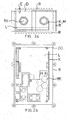
- FIG. 3a
- eine Ausführungsform der erfindungsgemäßen oberen Gehäuse-Kunststoffschalen in Draufsicht und
- FIG. 3b, 3c
- die obere Gehäuse-Kunststoffschale nach FIG. 3a in Seitenansicht,
- FIG. 4a, 4b
- eine Ausführungsform der erfindungsgemäßen unteren Gehäuse-Kunststoffschalen in Seitenansicht und
- FIG. 4c, 4d
- die untere Gehäuse-Kunststoffschale nach FIG. 4a, 4b in Draufsicht und Seitenansicht, teilweise im Schnitt,
- FIG. 5a, 5b
- eine Ausführungsform der Leiterplatte in Seitenansicht und in Draufsicht und
- FIG. 6a, 6c
- eine Ausführungsform des erfindungsgemäßen Kühlkörpers in Seitenansicht und
- FIG. 6b
- den Kühlkörper nach FIG. 6a, 6c in Draufsicht.
- FIG. 1
- An embodiment of the housing according to the invention without fastening means for the installation of the housing in a perspective view,
- FIG. 2a
- the housing of FIG. 1 in side view, partly in section and
- FIG. 2 B
- the housing of FIG. 2a opened and in plan view,
- FIG. 3a
- an embodiment of the upper housing plastic shells according to the invention in plan view and
- FIG. 3b, 3c
- the upper housing plastic shell of FIG. 3a in side view,
- FIG. 4a, 4b
- an embodiment of the lower housing plastic shells according to the invention in side view and
- FIG. 4c, 4d
- the lower housing plastic shell of FIG. 4a, 4b in plan view and side view, partly in section,
- FIG. 5a, 5b
- an embodiment of the circuit board in side view and in plan view and
- FIG. 6a, 6c
- an embodiment of the heat sink according to the invention in side view and
- FIG. 6b
- the heat sink of FIG. 6a, 6c in plan view.
FIG. 1 bis FIG. 6c zeigen im Detail das erfindungsgemäße Gehäuse mit einer Baugruppe, welche zur Steuerung/Überwachung der Befeuerung eines Flughafens eingesetzt wird. Die Baugruppe/Modul besteht aus einer Leiterplatte L für die elektronische Schaltung, die in das Gehäuse eingebaut ist.FIG. 1 to FIG. 6c show in detail the housing according to the invention with a Assembly, which is used to control / monitor the firing of a Airport is used. The module / module consists of a printed circuit board L for the electronic circuit, which is built into the housing.
Da die erfindungsgemäßen Gehäuse auf dem Flugfeld in Kabelschächten (auch unter Wasser) installiert werden, werden besondere Ansprüchen an die Dichtigkeit des Gehäuses gestellt. Die Schächte sind nicht klimatisiert und so unterliegt die Baugruppe/Modul extremen Temperaturschwankungen. Die Temperaturen können zwischen etwa -25°C bis +65°C schwanken, wobei die Baugruppe/Modul in allen Temperaturbereichen voll funktionsfähig sein muss. Die Schnittstellen sind durch Leitungen realisiert, die aus dem Gehäuse ragen, wobei die Leitungslänge jeweils ca. 0,5m beträgt. Da das Gehäuse wasserdicht sein soll (IP 68, d.h. wasserdicht bis zu einem Druck entsprechend 2m Wassersäule), muss es auch korrosionsfrei sein. Infolgedessen, dass auf Flughäfen zur Enteisung der Rollbahn bzw. zum Abtauen aggressive Taumittel eingesetzt werden und auch Treibstoff in die Schächte läuft, muss das Gehäuse säurefest sein. Es weist weiterhin eine Resistenz gegen Schadstoffe auf wie:
- Salzwasser (Meerwasser)
- Kraftstoffe (auch Kerosin, Flugbenzin)
- Flusswasser
- Luft (salzhaltig)
- Glysantin (max. 50%-ige Lösung in Wasser).
- Salt water (sea water)
- Fuels (also kerosene, jet fuel)
- river water
- Air (salty)
- Glysantin (maximum 50% solution in water).
Weiterhin darf das Gehäuse nicht elektrisch leitfähig und nicht brennbar sein. Zudem ist die mechanische Belastbarkeit zu beachten, d.h. das Gehäuse muss stabil und robust ausgelegt sein (trittfest). Da die Installation der erfindungsgemäßen Gehäuse sich unter der Erde befindet, müssen die Gehäuse nagetierfest sein. Um die im Inneren der Gehäuse entstehende Temperatur (ca. 20W Verlustleistung) möglichst gut ableiten zu können, soll der verwendete Kunststoff gute Wärmeleitfähigkeit besitzen.Furthermore, the housing must not be electrically conductive and non-combustible. In addition, the mechanical strength is observed, i. the housing must be stable and robust designed (resistant to treading). Because the installation of the Housing according to the invention is located below the ground, the housing must to be rodent-proof. To the resulting inside the housing temperature (approx. 20W power dissipation) as well as possible to derive the used Plastic have good thermal conductivity.
Zur Erfüllung vorstehender Anforderungen weist das erfindungsgemäße Gehäuse zwei Gehäuse-Kunststoffschalen B, D und einen im Gehäuse B, D angeordneten Kühlkörper K auf. Die Innenmaße des Gehäuse betragen ca. 117mm · 184mm · 58,6mm (Breite · Länge · Höhe). Die Außenmaße ergeben sich aus den Innenmaßen und den Wandstärken (3mm). Innerhalb des Gehäuses B, D entsteht im wesentlichen an zwei Funktionsgruppen Verlustleistung durch die Bauteile der Baugruppe/Modul, nämlich:
- durch den Gleichstromwiderstand der Drosselspulen
- durch Verluste in den Halbleitern für Stromversorgung und Sendeverstärker.
- through the DC resistance of the inductors
- due to losses in the semiconductors for power supply and transmitter amplifier.
Der Kühlkörper K ist erfindungsgemäß mit einer der beiden Gehäuse-Kunststoffschalen B, D durch vollständiges Umspritzen eines Teils des Kühlkörpers K fest verbunden und weist einen nicht umspritzten Abschnitt als Bauelemente-Montagefläche M auf, wodurch für die dort montierten Bauelemente BE das Gehäuse B, D als Wärmesenke wirkt.The heat sink K is according to the invention with one of the two housing plastic shells B, D by completely encapsulating a part of the Heatsink K firmly connected and has a non-overmolded section as Component mounting surface M on, causing the mounted there Components BE the housing B, D acts as a heat sink.
Der Kühlkörper K besteht aus einem wärmeleitenden Material und ist ein Aluminiumdruckgussteil oder ein Aluminiumfließpressteil. Die Bauelemente BE, d.h. die Halbleiter, sind mit Haltemittel, vorzugsweise u-förmige Clipse, an dem Aluminiumwinkel, der als Kühlkörper K dient, befestigt. Dieser Winkel K ist direkt in die Kunststoffschale B, d.h. in das Unterteil des Kunststoffgehäuses, mit eingespritzt und auf der Oberseite (zwischen Gehäuse und Baugruppe), mit Ausnahme einiger Aussparungen A zur Aufnahme in der Form (Negativ zu den Noppen am Werkzeug, an denen der Winkel K durch einen Schieber beim Spritzvorgang angepresst wird; Toleranzausgleich) und zur Optimierung der Wärmestrahlung, komplett mit Kunststoff bedeckt. Hierdurch lässt sich einerseits ein optimaler Wärmeübergang vom Aluminium zum Kunststoff und andererseits eine elektrische Isolierung der Baugruppe gegenüber dem' Aluminiumwinkel K, und somit Verhinderung von Kurzschlüssen zwischen verschiedenen Potentialen, erreichen. Das L-Profil (siehe FIG. 6a, FIG. 6b und FIG. 6c) hat beispielsweise die Maße 100mm · 150mm · 30mm · 3mm (Breite · Länge · Höhe · Dicke).The heat sink K is made of a thermally conductive material and is a Aluminum die casting or an aluminum extrusion. The components BE, i. the semiconductors are with holding means, preferably U-shaped clips on the aluminum angle, which serves as a heat sink K attached. This angle K is directly into the plastic shell B, i. in the lower part of the Plastic housing, with injected and on top (between housing and assembly), with the exception of a few recesses A for inclusion in the Shape (Negative to the nubs on the tool, where the angle K through a slider is pressed during the injection process; Tolerance compensation) and to Optimization of heat radiation, completely covered with plastic. hereby On the one hand, an optimal heat transfer from the aluminum to the Plastic and on the other hand electrical insulation of the assembly opposite the aluminum angle K, and thus prevention of Short circuits between different potentials, reach. The L-profile (see FIGS 6a, 6b and 6c) has, for example, the dimensions 100mm · 150mm · 30mm · 3mm (width · length · height · thickness).
Kühl-/Tragrippen R sowohl an der Gehäuse-Oberseite als auch an der Gehäuse-Unterseite vergrößern die Oberfläche und verbessern damit sowohl die Wärmeabfuhr als auch die Stabilität. Eine keil- oder trapezförmige Ausbildung der Rippen R, welche ca. 7mm hoch sind, verringert zwar die Oberfläche etwas, das Entstehen von Verwirbelungen wird aber reduziert, wodurch sich die Wärmeabstrahlung wieder verbessert. Cooling / support ribs R on both the top of the housing and the bottom of the housing enlarge the surface and thus improve both the Heat dissipation as well as the stability. A wedge or trapezoidal training the ribs R, which are about 7mm high, reduces the surface, However, the formation of turbulence is reduced, resulting in the Heat radiation improved again.
Zur Befestigung der Baugruppe/Leiterplatte L sind im Gehäuse-Unterteil B entsprechende Mittel DO, vorzugsweise Dome, vorgesehen. In diesen Domen DO lässt sich die Baugruppe/Leiterplatte L mittels selbstschneidenden Schrauben befestigen, wobei gleichzeitig ein ausreichender Abstand zwischen Leiterplatte L und Gehäuse-Unterteil B gewährleistet ist.To attach the module / circuit board L are in the lower housing part B. corresponding means DO, preferably domes provided. In these domes DO can the module / PCB L by means of self-tapping Fasten screws, while maintaining a sufficient distance between Printed circuit board L and housing lower part B is guaranteed.
Zur Verbesserung des EMV-Verhaltens (sowohl Ein- als auch Abstrahlung) kann das Gehäuse-Unterteil B von innen elektrisch leitfähig beschichtet sein. Hierbei ist der Bereich unter der Baugruppe/Leiterplatte L ausgespart, um Kurzschlüsse zu verhindern. Die Abschirmung unter der Leiterplatte L ist durch den eingespritzten Kühlkörper K realisiert. Weiterhin sind im Gehäuse-Oberteil D mehrere Bohrungen BO vorgesehen, in denen ein Blech zur elektromagnetischen Abschirmung mit selbstschneidenden Schrauben befestigt werden kann. Die Bohrungen in Ober- und Unterteil D, B sind so gestaltet, dass nur eine Schraubensorte erforderlich ist.To improve the EMC behavior (both incoming and outgoing radiation) For example, the lower housing part B may be electrically conductively coated from the inside. Here, the area under the assembly / circuit board L is recessed to Prevent short circuits. The shield under the circuit board L is through the injected heat sink K realized. Furthermore, in the housing upper part D several holes BO provided in which a sheet for electromagnetic shield attached with self-tapping screws can be. The holes in the upper and lower part D, B are designed so that only one type of screw is required.
Im Gehäuse-Oberteil D sind Niederhalter N integriert, die verhindern, dass sich die Clipse, mit denen die Halbleiter BE am Kühlkörper K befestigt sind, z.B. durch Vibration lösen können.In the housing top D hold-down N are integrated, which prevent themselves the clips with which the semiconductors BE are attached to the heat sink K, e.g. can be solved by vibration.
Zur Ableitung von Überspannungen, die z.B. durch Blitzschlag über die Leitungen auf die Baugruppe/Leiterplatte L geführt werden, ist eine Erdung notwendig. Hierfür ist im Gehäuse-Oberteil D ein Gewindebolzen E eingespritzt oder von innen eingepresst, an dem von der Innenseite ein Kabel zur Leiterplatte L führt. Im zuletzt genannten Fall ist auch eine Dichtung vorzusehen, damit die Wasserdichtigkeit gewährleistet ist. An der Außenseite kann ein Erdungskabel verschraubt werden. Die Leiterplatte L (siehe FIG. 5a und FIG. 5b) hat beispielsweise etwa die Maße 100mm · 170mm · 1,6mm (Breite · Länge · Dicke). Die Bauteile/Bauelemente BE auf der Oberseite haben eine maximale Höhe von ca. 48mm, auf der Unterseite ca. 2,5min. Die Befestigung der Leiterplatte L erfolgt mittels mehrerer Schrauben im Gehäuse. Hierzu befinden sich Bohrungen (ca. 3mm Durchmesser) in den Ecken der Leiterplatte. Es können selbstschneidende Schrauben zum Einsatz kommen.For deriving overvoltages, e.g. by lightning over the Leads are led to the module / PCB L, is a ground necessary. For this purpose, a threaded bolt E is injected in the housing upper part D. or pressed from the inside, on the inside of a cable to PCB L leads. In the latter case is also a seal provided so that the water resistance is ensured. On the outside a grounding cable can be screwed. The printed circuit board L (see FIG. 5a and FIG. 5b) has, for example, the dimensions 100mm x 170mm x 1.6mm (Width · length · thickness). The components / components BE have on the top a maximum height of about 48mm, on the bottom about 2.5min. The Fixing the circuit board L is done by means of several screws in the housing. For this there are holes (about 3mm diameter) in the corners of the PCB. Self-tapping screws can be used.
Im Gehäuse-Oberteil D ist innen umlaufend ein Steg S eingearbeitet. Dieser Steg S justiert das Gehäuse-Oberteil D während der Montage auf dem Gehäuse-Unterteil B, so dass es nicht verrutschen kann. Dies vereinfacht die Montage und stellt bei Passgenauigkeit eine gute Dichtheit sicher. Weiterhin besitzt das Gehäuse-Oberteil D am Rand innen eine umlaufende Nut NU, in die Dichtungsmasse direkt eingespritzt ist. Dadurch ist keine separate Form für einen Dichtungsring erforderlich. Weiterhin kann bei der Montage kein Dichtungsring verrutschen. Auch die verwendete Dichtungsmasse muss resistent gegen die oben erwähnten Schadstoffe sein.In the housing upper part D a web S is incorporated circumferentially inside. This Bridge S adjusts the housing upper part D during installation on the lower housing part B, so that it can not slip. This simplifies the assembly and ensures a good tightness when fitting accuracy. Furthermore, has the Housing top D at the edge inside a circumferential groove NU, in the Sealant is injected directly. This is not a separate form for a sealing ring required. Furthermore, during assembly no Slip the sealing ring. Also, the sealant used must be resistant to the above-mentioned pollutants.
Die Kabel sind durch metrische Kabelverschraubungen KV, beispielweise M20 x 1,5, ins Gehäuse geführt. Hierzu sind auf den beiden schmalen Seiten je zwei Bohrungen vorzusehen, die ein entsprechendes Gewinde besitzen. Die zwei Bohrungen auf der rechten Seite sind optional und sind in der Regel geschlossen, lassen sich aber bei Bedarf leicht ausbrechen. Falls erforderlich, können bei der Verschraubung KV Dichtungsringe zum Einsatz kommen, um die geforderte Dichtigkeit zu erreichen. Auch die verwendeten Dichtungen müssen resistent gegen die oben erwähnten Schadstoffe sein.The cables are metric cable glands KV, for example M20 x 1.5, led into the housing. For this purpose, two on the two narrow sides Provide holes that have a corresponding thread. The two Holes on the right are optional and are usually closed, but can easily break out when needed. If necessary, KV sealing rings can be used for the screw connection to achieve the required tightness. Also the used seals must be resistant to the above-mentioned pollutants.
Die beiden Gehäuseteile B, D sind mit mehreren beispielsweise selbstschneidenden Schrauben (ca. 4mm Gewindedurchmesser) miteinander zu verbinden. Im Gehäuse-Oberteil D ist in den Ecken je eine Befestigungsöse BÖ eingearbeitet. Das Gehäuse B, D kann also liegend oder auch in beliebiger Lage hängend eingebaut sein.The two housing parts B, D are with several example self-tapping screws (about 4mm thread diameter) together connect. In the housing upper part D is in each corner a fastening eye BÖ incorporated. The housing B, D can thus lying or in any position be installed hanging.
Das erfindungsgemäße Gehäuse gewährleistet eine einfache, funktionale, kostensparende und damit eine optimale Verwendbarkeit und reduziert damit ganz erheblich die Herstellungskosten. Der Kühlkörper K ist direkt in den Kunststoff des Gehäuseteils B eingegossen, wodurch jeweils im Verhältnis optimiert zueinander ein guter Wärmeübergang vom Kühlkörper K in das Gehäuse B, D, ein guter Wärmedurchgang und eine gute Wärmestrahlung erreicht wird: Weitere Vorteile sind: die elektrische Isolation zwischen Kühlkörper K und Bauteilen/Bauelementen BE; die einfach zu montierende Befestigung der Halbleiter BE am Kühlkörper K mittels Clipse, wodurch keine Verschraubung nötig ist und eine zusätzliche Kühlleistung der Clipse realisiert ist; die Integration der Niederhalter N im Gehäuseoberteil D, wodurch verhindert wird, dass sich die Clipse zur Befestigung der Halbleiter BE am Kühlkörper K beispielsweise durch Vibration lösen; die Ableitung von Überspannungen (Blitzschutz) durch die Erdungsdurchgangsschraube E im Gehäuseoberteil D; die größere Fläche bewirkt eine größere Kühlleistung durch die trapezförmige Außenfläche/Rippen R des Gehäuses B, D.The housing according to the invention ensures a simple, functional, cost-saving and thus optimal usability and thus reduced quite considerably the production costs. The heat sink K is directly in the Plastic cast the housing part B, which in each case in proportion optimized to each other a good heat transfer from the heat sink K in the Housing B, D, a good heat transfer and a good heat radiation Other advantages are: the electrical insulation between Heat sink K and components / components BE; the easy to install Attaching the semiconductor BE on the heat sink K by means of clips, which no Screwing is necessary and realized an additional cooling capacity of the clips is; the integration of the hold-down N in the upper housing part D, whereby prevents the clips to attach the semiconductor BE on Loosen heat sink K, for example by vibration; the derivative of Overvoltages (lightning protection) through the earthing through screw E in Housing upper part D; the larger area causes a greater cooling capacity the trapezoidal outer surface / ribs R of the housing B, D.
Fertigungstechnische Vorteile ergeben sich dadurch, dass der Kühlkörper K bei der Fertigung direkt mit ins Gehäuse-Unterteil B oder ins Gehäuse-Oberteil D eingespritzt wird. Dabei wird der Kühlkörper K auf Noppen als Distanzhalter am Werkzeug aufgelegt und Toleranzschwankungen des Aluminiums gehen direkt in die Wanddicke des Gehäuses ein, wenn der Schieber den Winkel K beim Spritzvorgang anpresst (d.h. Toleranzschwankungen werden dadurch kompensiert). Die Noppen am Werkzeug (das Negativ hierzu sind die Aussparungen A) können eine beliebige Form, beispielsweise dreieckig, kreisförmig usw. und Größe sowie Dichte der Verteilung aufweisen, wobei die Schwächung der Stabilität durch den Kühlkörper K und durch das profilierte Kunststoffgehäuse B, D mehr als kompensiert wird. Weiterhin ergibt sich ein Kostenvorteil dadurch, dass keine Frästeile für den Kühlkörper K notwendig sind und durch die nach innen hin offenen Flächen des Kühlkörpers K (Aussparungen A) das Verhältnis von Wärmeübergangswert zu Wärmedurchgangswert weiter optimiert wird. Schließlich kann ein handelsüblicher Spritzautomat benutzt werden und sowohl die Fertigung des profilierten Gehäuses gemäß der Erfindung als auch dessen Bestückung kann ebenfalls vollautomatisch erfolgt, indem in das vorgefertigte Gehäuse-Unterteil B die bestückte Leiterplatte L eingesetzt, befestigt und dann das Gehäuse-Oberteil D aufgesetzt und befestigt wird.Manufacturing advantages result from the fact that the heat sink K at the production directly into the housing lower part B or into the housing upper part D. is injected. In this case, the heat sink K on nubs as a spacer placed on the tool and tolerance variations of the aluminum go directly into the wall thickness of the housing when the slider is the angle K during the injection process (i.e. ) Compensated. The knobs on the tool (the negative for this are the Recesses A) can have any shape, for example triangular, have circular etc. and size and density of the distribution, wherein the Weakening of stability by the heat sink K and by the profiled Plastic housing B, D is more than compensated. Furthermore, there is a Cost advantage in that no milled parts for the heat sink K necessary are and through the inwardly open surfaces of the heat sink K (Recesses A) the ratio of heat transfer value to Heat transfer value is further optimized. Finally, one can commercial injection machine are used and both the production of the profiled housing according to the invention as well as its equipment can also fully automatic, by placing in the prefabricated housing lower part B the printed circuit board L is inserted, attached and then the housing upper part D is placed and fastened.
Das erfindungsgemäße trittfeste, wärmeableitende und -abstrahlende Kunststoffgehäuse mit Kühl-/Tragrippen 'und teilweise umspritztem, ins Gehäuseinnere ragendem Kühlkörper findet überall dort Anwendung, wo hohe Ansprüche an Dichtfähigkeit, Robustheit (einschließlich gegen Umwelteinflüssen) und ein Höchstmaß an effizienter Wärmeabführung gestellt werden, beispielsweise im Automobilbau, Schiffbau, Containerbau, Carawanbau, Fassadenbau, Silotechnik, Kälte- und Klimatechnik und Gerätebau für Telekommunikationstechnik und der industriellen Elektronik.The inventive solid, heat dissipating and radiating Plastic housing with cooling / support ribs' and partially overmoulded, ins Housing interior protruding heat sink is used wherever high Claims of sealing ability, robustness (including against Environmental influences) and a maximum of efficient heat dissipation be used, for example in the automotive industry, shipbuilding, container construction, Caravanning, facade construction, silo technology, refrigeration and air conditioning technology and Device construction for telecommunication technology and industrial electronics.
Alle dargestellten und beschriebenen Ausführungsmöglichkeiten, sowie alle in der Beschreibung und/oder der Zeichnung, offenbarten neuen Einzelmerkmale und ihre Kombination untereinander, sind erfindungswesentlich. Beispielsweise können die Stecker direkt ins Gehäuse (B und/oder D) eingeschraubt sein, wobei auch diese Verbindung und die Stecker selbst wasserdicht sind; die Baugruppe/Modul/Leiterplatte L kann vergossen sein, um unanfälliger gegenüber Umwelteinflüssen zu sein, wobei auch hier die Wärmeabfuhr nicht beeinträchtigt ist; es können Rastelemente vorsehen werden, mit denen beispielsweise die Leiterplatte L in dem Gehäuse (vorzugsweise in B) klemmend befestigt wird; es können weiterhin Hinterschneidungen oder andere Rastelemente am Gehäuse-Unterteil B vorgesehen werden, die beispielsweise dann das Gehäuse-Oberteil D halten; zur Verbesserung der Dichtigkeit am Gehäuse-Unterteil B die Auflagefläche (umgebogener Rand) verbreitert und darin eine Nut für eine weitere Dichtung vorgesehen werden usw.All illustrated and described execution options, as well as all in the description and / or the drawing disclosed new individual features and their combination with each other, are essential to the invention. For example the plugs can be screwed directly into the housing (B and / or D), wherein also this connection and the plug itself are waterproof; the Assembly / module / circuit board L may be potted to be less susceptible to be against environmental influences, but here, the heat dissipation not is impaired; It can be provided locking elements with which for example, the printed circuit board L in the housing (preferably in B) is attached by clamping; it can still be undercuts or other Locking elements are provided on the housing lower part B, for example then hold the housing top D; to improve the tightness on Housing base B the support surface (bent edge) widened and in a groove for another seal are provided, etc.
Claims (10)
Applications Claiming Priority (2)
| Application Number | Priority Date | Filing Date | Title |
|---|---|---|---|
| DE2002147828 DE10247828B4 (en) | 2002-10-14 | 2002-10-14 | Heat dissipating and radiating plastic housing with cooling / support ribs and molded heat sink and method for its production |
| DE10247828 | 2002-10-14 |
Publications (3)
| Publication Number | Publication Date |
|---|---|
| EP1422983A2 true EP1422983A2 (en) | 2004-05-26 |
| EP1422983A3 EP1422983A3 (en) | 2005-06-15 |
| EP1422983B1 EP1422983B1 (en) | 2018-07-18 |
Family
ID=32086890
Family Applications (1)
| Application Number | Title | Priority Date | Filing Date |
|---|---|---|---|
| EP03023036.1A Expired - Lifetime EP1422983B1 (en) | 2002-10-14 | 2003-10-13 | Wear resistant , heat conductive , heat radiating , plastic housing provided with supporting fins and overmolded heat sink for cooling, method of manufacturing the same |
Country Status (3)
| Country | Link |
|---|---|
| EP (1) | EP1422983B1 (en) |
| DE (1) | DE10247828B4 (en) |
| ES (1) | ES2690771T3 (en) |
Cited By (7)
| Publication number | Priority date | Publication date | Assignee | Title |
|---|---|---|---|---|
| EP1772877A1 (en) * | 2005-06-02 | 2007-04-11 | STS Spezial-Transformatoren-Stockach GmbH & Co. KG | MF transformer with improved heat dissipation |
| EP2194768A1 (en) * | 2008-12-04 | 2010-06-09 | Stribel Production GmbH | Energy storage device |
| EP2433478B1 (en) * | 2009-05-20 | 2013-06-26 | Robert Bosch GmbH | Housing or housing part for a control device of a motor vehicle |
| EP2849311A1 (en) * | 2013-09-16 | 2015-03-18 | Robert Bosch Gmbh | Battery charging device |
| EP2849310A1 (en) * | 2013-09-16 | 2015-03-18 | Robert Bosch Gmbh | Battery charging device |
| DE102018215876A1 (en) * | 2018-09-18 | 2020-03-19 | Bayerische Motoren Werke Aktiengesellschaft | Control device for a motor vehicle and motor vehicle with such a control device |
| WO2022078689A1 (en) * | 2020-10-14 | 2022-04-21 | Bayerische Motoren Werke Aktiengesellschaft | Holder for a control device of a vehicle, and vehicle |
Families Citing this family (11)
| Publication number | Priority date | Publication date | Assignee | Title |
|---|---|---|---|---|
| DE102005043055B3 (en) * | 2005-09-09 | 2006-12-21 | Siemens Ag | Electronics housing cooling body with cooling fins, useful in automobiles, is produced inexpensively from extruded profiled slabs, specifically of aluminum, by cutting to length using profiled circular saw |
| DE102007057533B4 (en) * | 2007-11-29 | 2016-07-07 | Fraunhofer-Gesellschaft zur Förderung der angewandten Forschung e.V. | Heat sink, method for manufacturing a heat sink and printed circuit board with heat sink |
| DE102012207675A1 (en) | 2012-05-09 | 2013-11-14 | Robert Bosch Gmbh | Arrangement for heat dissipation for a plastic housing with electronic components arranged therein |
| EP2827687B1 (en) | 2013-07-15 | 2019-03-13 | OSRAM GmbH | A method of producing a support structure for lightning devices |
| DE102014211438A1 (en) * | 2014-06-16 | 2015-12-17 | Robert Bosch Gmbh | Control unit with thermally conductive housing wall |
| DE102014211443A1 (en) * | 2014-06-16 | 2015-12-17 | Robert Bosch Gmbh | Control unit with thermally conductive housing wall |
| DE102016122601A1 (en) * | 2016-11-23 | 2018-05-24 | Atlas Elektronik Gmbh | Underwater vehicle with pressure vessel |
| DE102016122597A1 (en) * | 2016-11-23 | 2018-05-24 | Atlas Elektronik Gmbh | Underwater vehicle with pressure vessel |
| DE102017202431B3 (en) | 2017-02-15 | 2018-07-05 | Robert Bosch Gmbh | Control unit with a housing having cooling fins and method for closing a housing |
| WO2019061088A1 (en) * | 2017-09-27 | 2019-04-04 | Changzhou Globe Co., Ltd. | Plate for cooling a power tool |
| DE202021104219U1 (en) | 2021-08-06 | 2022-11-10 | Phoenix Contact Gmbh & Co. Kg | Electronics housing for mounting on a mounting rail and a system |
Citations (4)
| Publication number | Priority date | Publication date | Assignee | Title |
|---|---|---|---|---|
| DE3933123A1 (en) * | 1989-10-04 | 1991-04-11 | Bosch Gmbh Robert | HOUSING FOR AN ELECTRONIC CIRCUIT |
| GB2256531A (en) * | 1991-05-28 | 1992-12-09 | Greenfields Europ Limited | Heatsinking of electrical fittings |
| EP0757384A2 (en) * | 1995-07-31 | 1997-02-05 | Borg-Warner Automotive, Inc. | Method and apparatus for dissipating heat from an integrated circuit |
| DE10014457A1 (en) * | 2000-03-23 | 2001-10-04 | Ulrich Grauvogel | Cooling body e.g. for air conditioning system of motor vehicle, has housing for electronic circuit giving off heat with at least side walls made of plastic and joined to upper section of cooling body by molding round upper section |
Family Cites Families (13)
| Publication number | Priority date | Publication date | Assignee | Title |
|---|---|---|---|---|
| DE2511010A1 (en) * | 1975-03-13 | 1976-09-23 | Bosch Gmbh Robert | Cooling for electronic components - involves using components embedded in heat conductive mass of metal powder in resin which has large heat transfer surface |
| DE8704499U1 (en) * | 1987-03-26 | 1987-08-13 | Licentia Patent-Verwaltungs-Gmbh, 6000 Frankfurt, De | |
| DE8812158U1 (en) * | 1988-09-26 | 1988-12-22 | Siemens Ag, 1000 Berlin Und 8000 Muenchen, De | |
| DE8815604U1 (en) * | 1988-12-15 | 1989-02-02 | Kobald Electronic Geraete Gmbh, Wien, At | |
| DE3916899C2 (en) * | 1989-05-24 | 2003-04-03 | Bosch Gmbh Robert | Housing for an electronic circuit |
| DE19533298A1 (en) * | 1995-09-08 | 1997-03-13 | Siemens Ag | Electronic module with power components |
| JP3923111B2 (en) * | 1996-10-31 | 2007-05-30 | 古河電気工業株式会社 | Electrical junction box |
| DE19855389C2 (en) * | 1998-12-01 | 2002-10-31 | Siemens Ag | Electronic device |
| DE19857840C2 (en) * | 1998-12-15 | 2003-10-02 | Siemens Ag | Electronic device |
| DE19929209A1 (en) * | 1999-06-25 | 2001-01-18 | Siemens Ag | Electronic control device for car brake antiblocking systems, comprises carrier in which control connector is fitted and metallic cooling component soldered under it on further side from carrier and encapsulated in plastic |
| DE19953191A1 (en) * | 1999-11-05 | 2001-05-10 | Bosch Gmbh Robert | Electronic control unit |
| DE10013844A1 (en) * | 2000-03-15 | 2001-09-27 | Infineon Technologies Ag | Electric module cooling device e.g. for integrated circuits |
| DE10065857B4 (en) * | 2000-12-22 | 2005-04-14 | Siemens Ag | Heat transfer arrangement for a plastic housing of electronic assemblies |
-
2002
- 2002-10-14 DE DE2002147828 patent/DE10247828B4/en not_active Expired - Lifetime
-
2003
- 2003-10-13 EP EP03023036.1A patent/EP1422983B1/en not_active Expired - Lifetime
- 2003-10-13 ES ES03023036.1T patent/ES2690771T3/en not_active Expired - Lifetime
Patent Citations (4)
| Publication number | Priority date | Publication date | Assignee | Title |
|---|---|---|---|---|
| DE3933123A1 (en) * | 1989-10-04 | 1991-04-11 | Bosch Gmbh Robert | HOUSING FOR AN ELECTRONIC CIRCUIT |
| GB2256531A (en) * | 1991-05-28 | 1992-12-09 | Greenfields Europ Limited | Heatsinking of electrical fittings |
| EP0757384A2 (en) * | 1995-07-31 | 1997-02-05 | Borg-Warner Automotive, Inc. | Method and apparatus for dissipating heat from an integrated circuit |
| DE10014457A1 (en) * | 2000-03-23 | 2001-10-04 | Ulrich Grauvogel | Cooling body e.g. for air conditioning system of motor vehicle, has housing for electronic circuit giving off heat with at least side walls made of plastic and joined to upper section of cooling body by molding round upper section |
Cited By (14)
| Publication number | Priority date | Publication date | Assignee | Title |
|---|---|---|---|---|
| EP1772877A1 (en) * | 2005-06-02 | 2007-04-11 | STS Spezial-Transformatoren-Stockach GmbH & Co. KG | MF transformer with improved heat dissipation |
| EP2194768A1 (en) * | 2008-12-04 | 2010-06-09 | Stribel Production GmbH | Energy storage device |
| US8780566B2 (en) | 2008-12-04 | 2014-07-15 | Flextronics International Kft. | Energy storage device with gas-tight capacitor chamber |
| EP2433478B1 (en) * | 2009-05-20 | 2013-06-26 | Robert Bosch GmbH | Housing or housing part for a control device of a motor vehicle |
| CN104467069A (en) * | 2013-09-16 | 2015-03-25 | 罗伯特·博世有限公司 | Rechargeable battery charging device and system including rechargeable battery charging device |
| EP2849310A1 (en) * | 2013-09-16 | 2015-03-18 | Robert Bosch Gmbh | Battery charging device |
| EP2849311A1 (en) * | 2013-09-16 | 2015-03-18 | Robert Bosch Gmbh | Battery charging device |
| CN104467070A (en) * | 2013-09-16 | 2015-03-25 | 罗伯特·博世有限公司 | Battery charging device and system including battery charging device |
| US10601236B2 (en) | 2013-09-16 | 2020-03-24 | Robert Bosch Gmbh | Battery charging device |
| US10630088B2 (en) | 2013-09-16 | 2020-04-21 | Robert Bosch Gmbh | Battery charging device |
| CN104467069B (en) * | 2013-09-16 | 2020-10-02 | 罗伯特·博世有限公司 | Battery charging device and system comprising a battery charging device |
| CN104467070B (en) * | 2013-09-16 | 2020-10-02 | 罗伯特·博世有限公司 | Battery charging device and system comprising a battery charging device |
| DE102018215876A1 (en) * | 2018-09-18 | 2020-03-19 | Bayerische Motoren Werke Aktiengesellschaft | Control device for a motor vehicle and motor vehicle with such a control device |
| WO2022078689A1 (en) * | 2020-10-14 | 2022-04-21 | Bayerische Motoren Werke Aktiengesellschaft | Holder for a control device of a vehicle, and vehicle |
Also Published As
| Publication number | Publication date |
|---|---|
| EP1422983B1 (en) | 2018-07-18 |
| DE10247828B4 (en) | 2005-03-03 |
| DE10247828A1 (en) | 2004-05-06 |
| ES2690771T3 (en) | 2018-11-22 |
| EP1422983A3 (en) | 2005-06-15 |
Similar Documents
| Publication | Publication Date | Title |
|---|---|---|
| EP1422983B1 (en) | Wear resistant , heat conductive , heat radiating , plastic housing provided with supporting fins and overmolded heat sink for cooling, method of manufacturing the same | |
| EP1395098B1 (en) | Electrical heating for vehicle | |
| DE112015003987B4 (en) | Circuit assembly, electrical distributor and manufacturing method for a circuit assembly | |
| DE102005037488B4 (en) | Cooling arrangement and their use and compact drive and inverter with such a cooling arrangement | |
| DE102007057533B4 (en) | Heat sink, method for manufacturing a heat sink and printed circuit board with heat sink | |
| DE102015103096B4 (en) | Cooling device and cooling arrangement with the cooling device | |
| EP2439774A2 (en) | Heat distributor with flexible heat tube | |
| DE102012001917A1 (en) | Electric device | |
| EP2327286B1 (en) | Circuit housing having a heat coupling element | |
| DE102014201032A1 (en) | Electric control unit, transmission with an electric control unit and method for producing an electrical control unit | |
| DE2722142B2 (en) | Metallic housing wall for a housing accommodating electronic components | |
| WO2012101153A1 (en) | Arrangement for holding a plurality of electric energy storage cells | |
| EP2222150B1 (en) | Circuit board with cooling unit | |
| EP2317618A2 (en) | Electric installation device with at least one electric component which generates heat | |
| EP3841854B1 (en) | Method for mounting an electrical device | |
| DE202013002411U1 (en) | Heat spreader with flat tube cooling element | |
| DE10300175B4 (en) | Electronic assembly with heat-dissipating housing part | |
| DE19904279B4 (en) | Semiconductor device | |
| DE102011010431A1 (en) | Electrical device e.g. converter comprises a circuit board, which is equipped with heat-generating components, where the circuit board is arranged in a housing of the device and the housing comprises a cup-shaped housing portion | |
| DE112015004241B4 (en) | Electrical distributor | |
| DE102017128928B4 (en) | electronics package | |
| DE102018222748B4 (en) | cooler | |
| DE10306130A1 (en) | Electronic module for high frequency telecommunications, has screening and cooling, with insulating layer on components arranged in housing filled with liquid metal | |
| DE102005014413A1 (en) | Arrangement for heat dissipation | |
| EP3483930A1 (en) | Electronic unit |
Legal Events
| Date | Code | Title | Description |
|---|---|---|---|
| PUAI | Public reference made under article 153(3) epc to a published international application that has entered the european phase |
Free format text: ORIGINAL CODE: 0009012 |
|
| AK | Designated contracting states |
Kind code of ref document: A2 Designated state(s): AT BE BG CH CY CZ DE DK EE ES FI FR GB GR HU IE IT LI LU MC NL PT RO SE SI SK TR |
|
| AX | Request for extension of the european patent |
Extension state: AL LT LV MK |
|
| PUAL | Search report despatched |
Free format text: ORIGINAL CODE: 0009013 |
|
| AK | Designated contracting states |
Kind code of ref document: A3 Designated state(s): AT BE BG CH CY CZ DE DK EE ES FI FR GB GR HU IE IT LI LU MC NL PT RO SE SI SK TR |
|
| AX | Request for extension of the european patent |
Extension state: AL LT LV MK |
|
| 17P | Request for examination filed |
Effective date: 20051209 |
|
| AKX | Designation fees paid |
Designated state(s): AT BE BG CH CY CZ DE DK EE ES FI FR GB GR HU IE IT LI LU MC NL PT RO SE SI SK TR |
|
| RAP1 | Party data changed (applicant data changed or rights of an application transferred) |
Owner name: IAD GESELLSCHAFT FUER INFORMATIK, AUTOMATISIERUNG |
|
| 17Q | First examination report despatched |
Effective date: 20160628 |
|
| GRAP | Despatch of communication of intention to grant a patent |
Free format text: ORIGINAL CODE: EPIDOSNIGR1 |
|
| INTG | Intention to grant announced |
Effective date: 20180220 |
|
| GRAS | Grant fee paid |
Free format text: ORIGINAL CODE: EPIDOSNIGR3 |
|
| GRAA | (expected) grant |
Free format text: ORIGINAL CODE: 0009210 |
|
| AK | Designated contracting states |
Kind code of ref document: B1 Designated state(s): AT BE BG CH CY CZ DE DK EE ES FI FR GB GR HU IE IT LI LU MC NL PT RO SE SI SK TR |
|
| REG | Reference to a national code |
Ref country code: GB Ref legal event code: FG4D Free format text: NOT ENGLISH |
|
| REG | Reference to a national code |
Ref country code: CH Ref legal event code: EP |
|
| REG | Reference to a national code |
Ref country code: IE Ref legal event code: FG4D Free format text: LANGUAGE OF EP DOCUMENT: GERMAN |
|
| REG | Reference to a national code |
Ref country code: AT Ref legal event code: REF Ref document number: 1020766 Country of ref document: AT Kind code of ref document: T Effective date: 20180815 |
|
| REG | Reference to a national code |
Ref country code: DE Ref legal event code: R096 Ref document number: 50315765 Country of ref document: DE |
|
| REG | Reference to a national code |
Ref country code: NL Ref legal event code: MP Effective date: 20180718 |
|
| REG | Reference to a national code |
Ref country code: ES Ref legal event code: FG2A Ref document number: 2690771 Country of ref document: ES Kind code of ref document: T3 Effective date: 20181122 |
|
| PG25 | Lapsed in a contracting state [announced via postgrant information from national office to epo] |
Ref country code: NL Free format text: LAPSE BECAUSE OF FAILURE TO SUBMIT A TRANSLATION OF THE DESCRIPTION OR TO PAY THE FEE WITHIN THE PRESCRIBED TIME-LIMIT Effective date: 20180718 |
|
| PG25 | Lapsed in a contracting state [announced via postgrant information from national office to epo] |
Ref country code: SE Free format text: LAPSE BECAUSE OF FAILURE TO SUBMIT A TRANSLATION OF THE DESCRIPTION OR TO PAY THE FEE WITHIN THE PRESCRIBED TIME-LIMIT Effective date: 20180718 Ref country code: BG Free format text: LAPSE BECAUSE OF FAILURE TO SUBMIT A TRANSLATION OF THE DESCRIPTION OR TO PAY THE FEE WITHIN THE PRESCRIBED TIME-LIMIT Effective date: 20181018 Ref country code: FI Free format text: LAPSE BECAUSE OF FAILURE TO SUBMIT A TRANSLATION OF THE DESCRIPTION OR TO PAY THE FEE WITHIN THE PRESCRIBED TIME-LIMIT Effective date: 20180718 Ref country code: GR Free format text: LAPSE BECAUSE OF FAILURE TO SUBMIT A TRANSLATION OF THE DESCRIPTION OR TO PAY THE FEE WITHIN THE PRESCRIBED TIME-LIMIT Effective date: 20181019 |
|
| REG | Reference to a national code |
Ref country code: CH Ref legal event code: PK Free format text: BERICHTIGUNGEN |
|
| RIC2 | Information provided on ipc code assigned after grant |
Ipc: H05K 7/20 20060101AFI20040406BHEP |
|
| REG | Reference to a national code |
Ref country code: DE Ref legal event code: R097 Ref document number: 50315765 Country of ref document: DE |
|
| PG25 | Lapsed in a contracting state [announced via postgrant information from national office to epo] |
Ref country code: EE Free format text: LAPSE BECAUSE OF FAILURE TO SUBMIT A TRANSLATION OF THE DESCRIPTION OR TO PAY THE FEE WITHIN THE PRESCRIBED TIME-LIMIT Effective date: 20180718 Ref country code: CZ Free format text: LAPSE BECAUSE OF FAILURE TO SUBMIT A TRANSLATION OF THE DESCRIPTION OR TO PAY THE FEE WITHIN THE PRESCRIBED TIME-LIMIT Effective date: 20180718 Ref country code: RO Free format text: LAPSE BECAUSE OF FAILURE TO SUBMIT A TRANSLATION OF THE DESCRIPTION OR TO PAY THE FEE WITHIN THE PRESCRIBED TIME-LIMIT Effective date: 20180718 |
|
| PLBE | No opposition filed within time limit |
Free format text: ORIGINAL CODE: 0009261 |
|
| STAA | Information on the status of an ep patent application or granted ep patent |
Free format text: STATUS: NO OPPOSITION FILED WITHIN TIME LIMIT |
|
| PG25 | Lapsed in a contracting state [announced via postgrant information from national office to epo] |
Ref country code: SK Free format text: LAPSE BECAUSE OF FAILURE TO SUBMIT A TRANSLATION OF THE DESCRIPTION OR TO PAY THE FEE WITHIN THE PRESCRIBED TIME-LIMIT Effective date: 20180718 Ref country code: DK Free format text: LAPSE BECAUSE OF FAILURE TO SUBMIT A TRANSLATION OF THE DESCRIPTION OR TO PAY THE FEE WITHIN THE PRESCRIBED TIME-LIMIT Effective date: 20180718 |
|
| REG | Reference to a national code |
Ref country code: CH Ref legal event code: PL |
|
| 26N | No opposition filed |
Effective date: 20190423 |
|
| PG25 | Lapsed in a contracting state [announced via postgrant information from national office to epo] |
Ref country code: MC Free format text: LAPSE BECAUSE OF FAILURE TO SUBMIT A TRANSLATION OF THE DESCRIPTION OR TO PAY THE FEE WITHIN THE PRESCRIBED TIME-LIMIT Effective date: 20180718 Ref country code: LU Free format text: LAPSE BECAUSE OF NON-PAYMENT OF DUE FEES Effective date: 20181013 |
|
| REG | Reference to a national code |
Ref country code: IE Ref legal event code: MM4A |
|
| PG25 | Lapsed in a contracting state [announced via postgrant information from national office to epo] |
Ref country code: LI Free format text: LAPSE BECAUSE OF NON-PAYMENT OF DUE FEES Effective date: 20181031 Ref country code: CH Free format text: LAPSE BECAUSE OF NON-PAYMENT OF DUE FEES Effective date: 20181031 Ref country code: SI Free format text: LAPSE BECAUSE OF FAILURE TO SUBMIT A TRANSLATION OF THE DESCRIPTION OR TO PAY THE FEE WITHIN THE PRESCRIBED TIME-LIMIT Effective date: 20180718 |
|
| PG25 | Lapsed in a contracting state [announced via postgrant information from national office to epo] |
Ref country code: IE Free format text: LAPSE BECAUSE OF NON-PAYMENT OF DUE FEES Effective date: 20181013 |
|
| PG25 | Lapsed in a contracting state [announced via postgrant information from national office to epo] |
Ref country code: TR Free format text: LAPSE BECAUSE OF FAILURE TO SUBMIT A TRANSLATION OF THE DESCRIPTION OR TO PAY THE FEE WITHIN THE PRESCRIBED TIME-LIMIT Effective date: 20180718 |
|
| PG25 | Lapsed in a contracting state [announced via postgrant information from national office to epo] |
Ref country code: PT Free format text: LAPSE BECAUSE OF FAILURE TO SUBMIT A TRANSLATION OF THE DESCRIPTION OR TO PAY THE FEE WITHIN THE PRESCRIBED TIME-LIMIT Effective date: 20180718 |
|
| PG25 | Lapsed in a contracting state [announced via postgrant information from national office to epo] |
Ref country code: CY Free format text: LAPSE BECAUSE OF FAILURE TO SUBMIT A TRANSLATION OF THE DESCRIPTION OR TO PAY THE FEE WITHIN THE PRESCRIBED TIME-LIMIT Effective date: 20180718 Ref country code: HU Free format text: LAPSE BECAUSE OF FAILURE TO SUBMIT A TRANSLATION OF THE DESCRIPTION OR TO PAY THE FEE WITHIN THE PRESCRIBED TIME-LIMIT; INVALID AB INITIO Effective date: 20031013 |
|
| REG | Reference to a national code |
Ref country code: ES Ref legal event code: FD2A Effective date: 20220121 |
|
| PGFP | Annual fee paid to national office [announced via postgrant information from national office to epo] |
Ref country code: FR Payment date: 20221024 Year of fee payment: 20 |
|
| PGFP | Annual fee paid to national office [announced via postgrant information from national office to epo] |
Ref country code: IT Payment date: 20221011 Year of fee payment: 20 Ref country code: GB Payment date: 20221013 Year of fee payment: 20 Ref country code: ES Payment date: 20221123 Year of fee payment: 20 Ref country code: DE Payment date: 20221011 Year of fee payment: 20 Ref country code: AT Payment date: 20221011 Year of fee payment: 20 |
|
| PGFP | Annual fee paid to national office [announced via postgrant information from national office to epo] |
Ref country code: BE Payment date: 20221011 Year of fee payment: 20 |
|
| REG | Reference to a national code |
Ref country code: DE Ref legal event code: R071 Ref document number: 50315765 Country of ref document: DE |
|
| REG | Reference to a national code |
Ref country code: BE Ref legal event code: MK Effective date: 20231013 |
|
| REG | Reference to a national code |
Ref country code: ES Ref legal event code: FD2A Effective date: 20231026 |
|
| REG | Reference to a national code |
Ref country code: GB Ref legal event code: PE20 Expiry date: 20231012 |
|
| REG | Reference to a national code |
Ref country code: AT Ref legal event code: MK07 Ref document number: 1020766 Country of ref document: AT Kind code of ref document: T Effective date: 20231013 |
|
| PG25 | Lapsed in a contracting state [announced via postgrant information from national office to epo] |
Ref country code: GB Free format text: LAPSE BECAUSE OF EXPIRATION OF PROTECTION Effective date: 20231012 |
|
| PG25 | Lapsed in a contracting state [announced via postgrant information from national office to epo] |
Ref country code: ES Free format text: LAPSE BECAUSE OF EXPIRATION OF PROTECTION Effective date: 20231014 |
|
| PG25 | Lapsed in a contracting state [announced via postgrant information from national office to epo] |
Ref country code: GB Free format text: LAPSE BECAUSE OF EXPIRATION OF PROTECTION Effective date: 20231012 Ref country code: ES Free format text: LAPSE BECAUSE OF EXPIRATION OF PROTECTION Effective date: 20231014 |