EP2191352B1 - Dispositif de projection d'image et procédé de commande de ce dispositif - Google Patents
Dispositif de projection d'image et procédé de commande de ce dispositif Download PDFInfo
- Publication number
- EP2191352B1 EP2191352B1 EP08829117.4A EP08829117A EP2191352B1 EP 2191352 B1 EP2191352 B1 EP 2191352B1 EP 08829117 A EP08829117 A EP 08829117A EP 2191352 B1 EP2191352 B1 EP 2191352B1
- Authority
- EP
- European Patent Office
- Prior art keywords
- projection
- image
- display
- unit
- insertion direction
- Prior art date
- Legal status (The legal status is an assumption and is not a legal conclusion. Google has not performed a legal analysis and makes no representation as to the accuracy of the status listed.)
- Not-in-force
Links
- 238000000034 method Methods 0.000 title claims description 34
- 238000003780 insertion Methods 0.000 claims description 134
- 230000037431 insertion Effects 0.000 claims description 134
- 238000001514 detection method Methods 0.000 claims description 67
- 238000010586 diagram Methods 0.000 description 28
- 230000005484 gravity Effects 0.000 description 7
- 230000007257 malfunction Effects 0.000 description 3
- 230000003287 optical effect Effects 0.000 description 3
- 230000015556 catabolic process Effects 0.000 description 2
- 238000006731 degradation reaction Methods 0.000 description 2
- 239000000284 extract Substances 0.000 description 2
- 239000002131 composite material Substances 0.000 description 1
- 230000000694 effects Effects 0.000 description 1
- 238000000605 extraction Methods 0.000 description 1
- 238000003384 imaging method Methods 0.000 description 1
- 230000002452 interceptive effect Effects 0.000 description 1
- 238000000926 separation method Methods 0.000 description 1
Images


Classifications
-
- H—ELECTRICITY
- H04—ELECTRIC COMMUNICATION TECHNIQUE
- H04N—PICTORIAL COMMUNICATION, e.g. TELEVISION
- H04N9/00—Details of colour television systems
- H04N9/12—Picture reproducers
- H04N9/31—Projection devices for colour picture display, e.g. using electronic spatial light modulators [ESLM]
- H04N9/3191—Testing thereof
- H04N9/3194—Testing thereof including sensor feedback
-
- G—PHYSICS
- G03—PHOTOGRAPHY; CINEMATOGRAPHY; ANALOGOUS TECHNIQUES USING WAVES OTHER THAN OPTICAL WAVES; ELECTROGRAPHY; HOLOGRAPHY
- G03B—APPARATUS OR ARRANGEMENTS FOR TAKING PHOTOGRAPHS OR FOR PROJECTING OR VIEWING THEM; APPARATUS OR ARRANGEMENTS EMPLOYING ANALOGOUS TECHNIQUES USING WAVES OTHER THAN OPTICAL WAVES; ACCESSORIES THEREFOR
- G03B21/00—Projectors or projection-type viewers; Accessories therefor
-
- G—PHYSICS
- G06—COMPUTING; CALCULATING OR COUNTING
- G06F—ELECTRIC DIGITAL DATA PROCESSING
- G06F3/00—Input arrangements for transferring data to be processed into a form capable of being handled by the computer; Output arrangements for transferring data from processing unit to output unit, e.g. interface arrangements
- G06F3/01—Input arrangements or combined input and output arrangements for interaction between user and computer
- G06F3/03—Arrangements for converting the position or the displacement of a member into a coded form
- G06F3/041—Digitisers, e.g. for touch screens or touch pads, characterised by the transducing means
- G06F3/042—Digitisers, e.g. for touch screens or touch pads, characterised by the transducing means by opto-electronic means
- G06F3/0425—Digitisers, e.g. for touch screens or touch pads, characterised by the transducing means by opto-electronic means using a single imaging device like a video camera for tracking the absolute position of a single or a plurality of objects with respect to an imaged reference surface, e.g. video camera imaging a display or a projection screen, a table or a wall surface, on which a computer generated image is displayed or projected
-
- G—PHYSICS
- G06—COMPUTING; CALCULATING OR COUNTING
- G06V—IMAGE OR VIDEO RECOGNITION OR UNDERSTANDING
- G06V10/00—Arrangements for image or video recognition or understanding
- G06V10/10—Image acquisition
- G06V10/12—Details of acquisition arrangements; Constructional details thereof
- G06V10/14—Optical characteristics of the device performing the acquisition or on the illumination arrangements
- G06V10/145—Illumination specially adapted for pattern recognition, e.g. using gratings
-
- G—PHYSICS
- G06—COMPUTING; CALCULATING OR COUNTING
- G06V—IMAGE OR VIDEO RECOGNITION OR UNDERSTANDING
- G06V40/00—Recognition of biometric, human-related or animal-related patterns in image or video data
- G06V40/20—Movements or behaviour, e.g. gesture recognition
- G06V40/28—Recognition of hand or arm movements, e.g. recognition of deaf sign language
-
- H—ELECTRICITY
- H04—ELECTRIC COMMUNICATION TECHNIQUE
- H04N—PICTORIAL COMMUNICATION, e.g. TELEVISION
- H04N9/00—Details of colour television systems
- H04N9/12—Picture reproducers
- H04N9/31—Projection devices for colour picture display, e.g. using electronic spatial light modulators [ESLM]
- H04N9/3179—Video signal processing therefor
Definitions
- the present invention relates to an image display apparatus (image projection apparatus) that projects an image and a control method for the same, and more particularly, to an image display apparatus (image projection apparatus) capable of utilizing a projected image as a user interface for operating the image display apparatus (image projection apparatus), and a control method for the same.
- an image projection apparatus (herein also referred to as image display apparatus) as typified by a projector is designed to project video images output by a computer, media player, or the like for viewing purposes, and is used not only in conference rooms and stores, of course, but also in homes.
- the conventional projector because it is designed to project onto a large screen, is relatively large itself, and is usually affixed to the ceiling or placed on a desk or the floor when in use.
- the document US 2001/0012001 A1 discloses an information input apparatus, for which are provided an infrared LED panel for always applying infrared light to the back surface of a semi-transparent screen, a CCD camera for capturing only infrared light coming from the semi-transparent screen, and a projector for projecting an image onto the semi-transparent screen (with light not including infrared light).
- an infrared LED panel for always applying infrared light to the back surface of a semi-transparent screen
- a CCD camera for capturing only infrared light coming from the semi-transparent screen
- a projector for projecting an image onto the semi-transparent screen (with light not including infrared light).
- a control device picks up a variation in reflection light quantity as detection image information based on an imaging signal of the CCD camera.
- control device executes controls necessary for, for instance, switching of an interface image to be displayed on the semi-transparent screen.
- a manipulation method may be in such a form as to cause a variation in detection image information through reflection of infrared light. Interactive input/output with various manipulation methods is thus enabled.
- a display system comprising: a display device being arranged to generate a first view in a first direction relative to the display device and to generate a second view in a second direction relative to the display device, the second direction being different from the first direction; user-input means for accepting user-input by means of detecting a position of a hand of an user or of a pointing device held by the hand, the position relative to the display device, the user-input means being arranged to control the first view and the second view on basis of the detection; and observation means for observation of the user and arranged to detect whether the user-input is provided to control the first view or the second view, on basis of the observation.
- the present invention is conceived in light of the problem described above, and provides an image display apparatus (image projection apparatus) that can be easily operated even while projecting an image, and a control method for the same.
- an image display apparatus (image projection apparatus), as defined in claims 1 to 11.
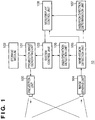
- FIG. 1 is a block diagram showing one configuration example of an image projection apparatus 10 according to a first embodiment of the present invention.
- a projection unit 100 includes a light source, lens, display device, and the like, and projects an image supplied from a projection image generating unit 101.
- the projection image generating unit 101 generates a projection image from image data stored on a storage medium 102 such as a memory card and supplies the projection image to the projection unit 100.
- a system control unit 103 is a microprocessor including, for example, a CPU, a ROM, and a RAM. By the CPU reading into the RAM a program stored in the ROM and executing it, the system control unit 103 controls operation of the image projection apparatus 10.
- An image sensing unit 104 is, for example, a camera capable of projecting a moving image, and includes an image sensing element, such as a CCD image sensor or a CMOS image sensor, and a lens for forming an optical object image on the image sensing element. It should be noted that, in the present embodiment, the image sensing unit 104 is an infrared camera capable of image sensing only an infrared region. In addition, in the present embodiment an image sensing range of the image sensing unit 104 is a range that includes a projection range of the projection unit 100. The image sensing unit 104 supplies sensed images to a hand-region detection unit 105.
- an image sensing element such as a CCD image sensor or a CMOS image sensor
- the hand-region detection unit 105 detects, as one example of a predetermined, particular object, a human hand, specifically, an image region (a hand region) identified as a human hand. Information relating to the detected hand region is given to a user operation detection unit 106 and an insertion direction determination unit 107.
- the user operation detection unit 106 detects the user operation based on the information relating to the hand region.
- the insertion direction determination unit 107 determines a moving direction of the hand that is the predetermined object as the insertion direction and outputs determination results to a menu display control unit 108.
- the menu display control unit 108 controls menu display based on the insertion direction of the hand on the projected image.
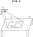
- FIG. 2 is a diagram showing schematically an example of an appearance and a state of use of the image projection apparatus 10 shown in FIG. 1 .
- the state is shown in which the projection surface is a horizontal surface formed by a desk or a table, and a projected image 211 is projected onto the projection surface 210.
- the system control unit 103 specifies one of the multiple pieces of image data recorded on the storage medium 102 and outputs the readout request to the projection image generating unit 101.
- the projection image generating unit 101 reads out the specified image data from the storage medium 102, and carries out processes, for example, decoding the image data if the image dated is encoded, so as to generate image data (image for display) in order to display on the projection unit 100.
- the image for display is supplied to the projection unit 100, and the projection unit 100 projects the image based on the image for display.
- the user may specify the image to be projected from among the multiple pieces of image data stored on the storage medium 102.
- This specification can be carried out using any known method, such as using a file browser that the Operation System software provides.
- the image sensing unit 104 is an infrared camera capable of sensing only the infrared region, and senses a region on the projection range, in other words on the projection surface including the projected image.
- the image sensing unit 104 outputs image data obtained by image sensing to the hand-region detection unit 105 in, for example, units of frames.
- the hand-region detection unit 105 detects a region corresponding to a predetermined object, in this case, as one example, a region corresponding to the user's hand (hand region).
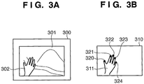
- FIG. 3A shows an example of a state in which a user's hand 302 intrudes into (is inserted into) a projected image 301 on a projection surface 300.
- the hand region detection unit 105 can extract the user's hand region from an infrared image using a method similar to a method described in, for example, Japanese Patent Application Publication No. 2005-236746 .
- the image sensing unit 104 is an infrared camera, it measures radiant light from the user's hand region and extracts only those objects with temperatures in a predetermined range (approximately 30°C-34°C, which is approximately the temperature of the human body). As a result, in the sensed image only the user's hand region appears.
- the hand-region detection unit 105 after processing the sensed image data supplied from the image sensing unit 104 to remove noise, detects the hand region and fingertip positions using pattern matching.
- FIG. 3B shows a hand region 311 and fingertip positions 320-324 detected from an image 310 sensed by the image sensing unit 104 in the state shown in FIG. 3A .
- the hand-region detection unit 105 as information relating to the detected hand region, for example, outputs information indicating a range of the hand region and information indicating the fingertip positions to the user operation detection unit 106, the insertion direction determination unit 107, and the menu and display control unit of 108.
- the insertion direction determination unit 107 is a moving direction determination means that determines the moving direction of a predetermined object. Specifically, the insertion direction determination unit 107 determines from which direction the user's hand is inserted into the projected image. Below a description is given of the operation of the insertion direction determination unit 107, using FIG. 4 and FIGS. 5A-5C .
- FIG. 4 is a flow chart illustrating the insertion direction determination operation.
- FIGS. 5A-5C are diagrams illustrating a predetermined object moving direction (hereinafter referred to as insertion direction) determination example in the present embodiment.
- the insertion direction determination unit 107 based on information relating to the hand region input from the hand region detection unit 105 computes the center of gravity of the hand region.
- the center of gravity can for example be computed as the average coordinates of the pixels contained in the hand region detected by the hand region detection unit 105.
- other methods may be used, such as obtaining the center of gravity of an external quadrilateral enclosing the hand region.
- the insertion direction determination unit 107 detects the representative fingertip position. As described above, although in the hand region detection unit 105 detection of the fingertip positions is completed, from among a plurality of fingertip positions a representative fingertip position to be used as a position that operates a GUI image is determined. Here, that fingertip position which is at the greatest distance from the center of gravity is made the representative fingertip position.
- FIG. 5A is a diagram showing an example of a representative fingertip position 503 and a center of gravity 502 computed for a hand region 501.
- the insertion direction determination unit 107 computes a hand insertion angle. Specifically, as shown in FIG. 5B , the insertion direction determination unit 107 computes an angle ⁇ of a vector v extending from the center of gravity 502 of the hand to the representative fingertip position 503 with respect to a bottom side of the projected image as the insertion angle.
- the vector v is referred to as the insertion direction vector.
- the insertion direction determination unit 107 determines an insertion direction that is found to be the closest among predetermined insertion directions. For example, assume that the predetermined insertion direction is either a top direction (1), a left direction (2), a bottom direction (3), or a right direction (4) as shown in FIG. 5C . In this case, the angle of the vector with respect to each direction is 90°, 180°, 270°, 0°.
- the top direction (1) is determined to be the closest insertion direction. It should be noted that in a case in which the angle of the insertion direction vector v is an angle of intermediate value with respect to the predetermined directions, such as 45°, 135°, 225°, 315°, the determination method may be determined as convenient.
- the insertion direction determination unit 107 determines the insertion direction of the hand and outputs determination results to the menu display control unit 108.
- the hand region detection and insertion direction determination processes described above may be executed for all the images sensed by the image sensing unit 104, and may be executed at each predetermined time period. For example, in a case in which the image sensing unit 104 senses 15 frames of images every second, of those 15 frames, hand reaching detection and insertion and direction determination can be carried out for one frame.
- the frequency of processing may be determined as convenient, balancing system load and required detection accuracy.
- FIG. 6 is a flow chart showing one example of operation of the menu display control unit 108.
- menu means an operation menu that is a GUI image superimposed on the projected image to enable the user to give instructions to the image projection apparatus 10 by operating the projected image.
- the menu display control unit 108 determines at least one of a display position and a display direction of the menu, based on detection results from the hand region detection unit 105 and on determination results from the insertion direction determination unit 107.
- the menu display control unit 108 determines whether or not a hand (or a predetermined object) as an object for the purpose of operating the GUI image exists on (is inserted in) the projected image for at least a certain time period. Specifically, the menu display control unit 108 can make this determination based on whether or not the insertion direction is supplied continuously for at least a certain time period from the insertion direction determination unit 107. Alternatively, the same determination can also be carried out based on whether or not the hand region is detected continuously for at least a certain time period from information relating to the hand region from the hand region detection unit 105.
- the menu display control unit 108 advances processing to S602. On the other hand, if insertion of the hand is not detected or is found to be not detected continuously for at least a certain time period, then the menu display control unit 108 determines that the hand is not inserted, and terminates processing.
- the menu display control unit 108 determines the rotation angle (display angle) of the menu depending on the insertion direction provided from the insertion direction determination unit 107.
- FIGS. 7A-7D are diagrams showing examples of a relation between a determined insertion direction and a menu rotation angle in the present embodiment.
- FIGS. 7A-7D show examples of menu rotation angles for the predetermined insertion directions (1)-(4) shown in FIG. 5C .
- Menus 701-704 are rotated and displayed at angles that depend on the insertion direction of the hand. For example, in a case in which it is determined that the insertion direction is from the right side of the projected image (moving left) like (2) in FIG. 5C , the menu display control unit 108 rotates the menu 90° so that the left edge of the projected image is at the top as shown in FIG. 7B . In other words, the menu display control unit 108 determines the rotation angle of the menu so that the insertion direction of the hand and the top of the menu always match.
- the menu display control unit 108 determines the display position of the menu depending on the position of the hand.
- FIGS. 8A-8D are diagrams showing examples of a relation between the position of the hand and the display position of the menu.
- FIGS. 8A and 8C are diagrams showing examples of the positions at which the menu can be superimposed in the image projection apparatus 10 of the present embodiment
- FIGS. 8B and 8D are diagrams showing positions of the hand and the menu display positions determined depending on the position of the hand.
- the image projection apparatus 10 of the present embodiment decides as the menu display position a position nearest in the vicinity of the representative fingertip position as well as separated in the insertion direction of the hand.
- FIG. 8A shows candidate display positions 810-812 when the hand insertion direction is the direction (1) shown in FIG. 5C .
- the candidate display position 810 that is closest from the representative fingertip position 801 in the insertion direction of the hand is determined as the display position of the menu 802.
- FIG. 8C shows candidate display positions 820-824 when the hand insertion direction is the direction (4) shown in FIG. 5C .
- the candidate display position 822 closest to the representative fingertip position 803 in the insertion direction of the hand is determined as the display position of the menu 804.
- the candidate display position closest to the representative fingertip position or the candidate display position closest to the edge of the projected image on the side of the insertion direction of the hand is decided as the display position. That is, for example, in the case of FIG. 8A , the candidate display position 810 is determined as the display position, and in the case of FIG. 8C , the candidate display position 824 is determined as the display position.
- more candidate display positions may be set, and a position in the vicinity of the representative fingertip position of the hand separated a predetermined distance in the insertion direction may be determined as the display position, without setting particular candidate display positions.
- the menu display control unit 108 sends a request to the system control unit 103 to superimpose and display the menu on the projected image. Moreover, the menu display control unit 108 also sends the determined menu display position and rotation angle information to the system control unit 103.
- the system control unit 103 once it receives a menu display request from the menu display control unit 108, sends the menu display position and rotation angle information to the projection image generating unit 101.
- the projection image generating unit 101 rotates a pre-registered menu image based on the rotation angle information. Then, the projection image generating unit 101 superimposes on the image from the storage medium 102 the menu image at the position corresponding to the menu display position and generates an image for display, which it then outputs to the projection unit 100. In this manner, an image on which the menu is superimposed is projected from the projection unit 100.
- FIGS. 9A-9D Examples of menu display results are shown in FIGS. 9A-9D.
- FIG. 9A shows a state in which the projected image is composed of only the image read out from the storage medium 102, without the insertion of the user's hand into the projected image 901.
- FIG. 9B shows a state in which the user's hand is inserted into the projected image 901 for a certain time period and a menu 902 is superimposed on the projected image 901 at a display position depending on the insertion direction of the hand and the position of the hand.
- the user operation detection unit 106 detects user instruction operations based on information relating to the hand region provided from the hand region detection unit 105, and outputs detected instruction operation information to the system control unit 103.
- User instruction operations are, for example, pointing operations with the user's hand like that shown in FIG. 9C .
- the pointing operation can be detected on the basis of, for example, the fact that the number of pieces of fingertip position information is one, or the distinctive features of the shape of the hand region.
- the user operation detection unit 106 when it detects a user pointing operation, outputs fingertip position information to the system control unit 103.
- the system control unit 103 determines if the user instruction operation is continuing for at least a predetermined time period. In other words, the system control unit 103 checks if the fingertip position continues to exist over a predetermined time period within a region of the buttons included in the menu 902 as shown in FIG. 9C . In a case in which it is determined that the fingertip position continues to exist over at least a predetermined time period within a region of the buttons included in the menu 902, the system control unit 103 determines that the user is operating that menu item, and carries out operation according to the menu item.
- FIG. 9C shows a state in which a fingertip position 904 continues to exist over at least a predetermined time period in the region of a button 903 included in the menu 902.
- the system control unit 103 determines that button 903 is being operated, and carries operation according to button 903.
- button 903 is a button that switches the projected image to the next image stored on the storage medium 102
- the system control unit 103 causes the projection image generating unit 101 to read out the next image and generate an image for display superimposed on the menu 902.
- the projected image is switched to that shown for example in FIG. 9D .
- the user may be notified by voice or the like that a determination that a menu item has been operated has been made, thus relieving the user of the need to continue to indicate the menu item for an extended period of time, thereby improving usability.
- the image projection apparatus of the present embodiment comprises an insertion direction detection unit that detects an insertion direction of a hand of a user inserted into a projected image, and a menu display control unit that decides a position and a rotation angle of a menu display depending on the insertion direction of the hand.
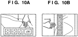
- FIGS. 10A and 10B are diagrams showing examples of cases in which both the menu and the image are rotated and projected depending on the insertion direction of the hand.
- FIG. 10A shows an example of a case in which the insertion direction of the hand is the (3) shown in FIG. 5C .
- FIG. 10B shows an example of a case in which the insertion direction of the hand is the (4) shown in FIG. 5C .
- the image and the menu are rotated and displayed so that the insertion direction of the hand is at the top.
- the projection image generating unit 101 based on rotation information from the system control unit 103, rotates the composite image resulting from the superimposition of the menu onto the image from the storage medium 102 (the image for display) so as to be able to achieve the display shown in FIG. 10A and FIG. 10B .
- the insertion direction determination unit 107 determines the insertion direction of the hand from the representative fingertip position and the center of gravity of the hand region.
- determination of the insertion direction of a hand may be carried out based on any condition.
- the moving direction of the representative fingertip position may be determined as the insertion direction.
- the insertion direction of the hand may be determined from the representative fingertip position and the relative positions of the hand region and the sides of the projected image.
- a hand region 1100 and a representative fingertip position 1101 are detected by the hand region detection unit 105.
- the hand region detection unit 105 From a center 1103 of a region 1102 where the hand region contacts the side of a projected image 1105, it can be determined that the insertion direction of the hand is toward the representative fingertip position 1101.
- the hand region contacts two sides of the projected image 1105 at contact portions 1112 and 1113.
- the insertion direction of the hand is a direction toward the representative fingertip position 1111.
- the image sensing unit 104 be an infrared camera.
- the image sensing unit 104 it is also possible to use a camera that senses images in the visible light region, in which case detection of the hand region can be accomplished by extracting a skin color pixel region from the sensed image and carrying out pattern matching to a shape pattern.
- a camera that senses images in the visible light region it is also possible to control so that the sensed images are recorded on the storage medium 102.
- the configuration of the image projection apparatus of the second embodiment may be identical to the configuration of the first embodiment shown in FIG. 1 , and therefore a description thereof is omitted. Moreover, the operation of the image projection apparatus of the second embodiment may be the same as that of the first embodiment except for the control operation performed by the menu display control unit 108, and therefore only a description of the operation of the menu display control unit 108 is given below.
- the menu display control unit 108 determines whether the hand no longer exists on (has separated from) the projected image. Specifically, whether or not the hand has been inserted for a certain time period can be determined in the same way as in S601 in FIG. 6 in the first embodiment. In addition, from the fact that the hand region can no longer be detected it can be determined that the hand has separated from the projected image. Moreover, the menu display control unit 108, as the insertion direction of the hand, determines the insertion direction last detected prior to a point in time when it is determined that the hand has separated from the projected image as the ultimate insertion direction.
- the menu display control unit 108 decides the rotation angle of the menu depending on the insertion direction of the hand. This process is the same as the control carried out in S602 in FIG. 6 .
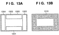
- the menu display control unit 108 decides the display position of the menu depending on the insertion direction of the hand. In the present embodiment, because menu display is carried out in a state in which the hand is not on the projected image, that end portion of the projected image which is most likely to be nearest the hand is decided as the display position.
- FIG. 13A An example of a candidate display position for the menu in the image projection apparatus 10 of the present embodiment is shown in FIG. 13A .
- menu candidate display positions 1301-1304 are disposed along the four edges of a projected image 1300, corresponding to each of the insertion directions (1)-(4) shown in FIG. 5C .
- the candidate display position 1301 is decided as the display position
- the candidate display position 1303 is decided as the display position, respectively.
- FIG. 13B is a diagram showing a state in which menus are displayed for each of the candidate display positions 1301-1304.
- the menu display control unit 108 sends a request to the system control unit 103 to display the menu superimposed on the projected image, the same as in S604 in FIG. 6 .
- the menu display control unit 108 also sends the decided menu display position and rotation angle information to the system control unit 103.
- the system control unit 103 once it receives a menu display request from the menu display control unit 108, sends the menu display position and rotation angle information to the projection image generating unit 101.
- the projection image generating unit 101 rotates a pre-registered menu image based on the rotation angle information. Then, the projection image generating unit 101 superimposes on the image from the storage medium 102 the menu image at the position corresponding to the menu display position and generates an image for display, which it then outputs to the projection unit 100. In this manner, an image on which the menu is superimposed is projected from the projection unit 100. This process also is the same as in the first embodiment.
- FIGS. 14A-14C An example of menu display results is shown in FIGS. 14A-14C.
- FIG. 14A shows a state in which the user's hand is inserted into a projected image 1401.
- FIG. 14B shows a state in which the inserted user's hand is withdrawn from (separated from) the projected image.
- the menu display control unit 108 holds the last detected insertion direction. Then, once the hand is withdrawn from the projected image, that is, when the hand region is no longer detected, a menu display request is sent from the menu display control unit 108 to the system control unit 103. Subsequently, as shown in FIG. 14C , the menu is superimposed on the projected image and displayed at a position corresponding to the insertion direction.
- the user operation detection unit 106 detects a user instruction operation based on information relating to the hand region from the hand region detection unit 105, and outputs information on the detected instruction operation to the system control unit 103. Detection of the user instruction operation may be carried out in the same way as in the first embodiment.
- the user operation detection unit 106 once it detects a user pointing operation, outputs fingertip position information to the system control unit 103.
- the system control unit 103 determines if the user instruction operation is continuing for at least a predetermined time period. In a case in which it is determined that the fingertip position continues to exist over at least a predetermined time period within the region of the menu items, the system control unit 103 determines that the user is operating that menu item, and carries out operation according to the menu item.
- the system control unit 103 In a case in which there is no instruction operation by the user for a certain time period, the system control unit 103 un-displays the menu and waits for the user's hand to again separate from the projected image.
- the image projection apparatus of the present embodiment carries out menu display when a hand inserted into the projected image separates from the projected image. Moreover, the image projection apparatus of the present embodiment controls the rotation angle and the display position of the menu depending on the insertion direction of the hand immediately prior to separation of the hand from the projected image.
- the insertion direction of the hand detected immediately prior to a point in time when it is determined that the hand has separated from the projected image is taken as the insertion direction of the hand
- the insertion direction may be determined by other methods .
- it is also possible to employ a method in which an insertion direction detected for the longest period of time (most number of times) within a certain time period within which the hand has been inserted can be decided as the ultimate insertion direction of the hand.
- the distinctive feature of the image projection apparatus of the present embodiment is controlling the display position and rotation angle of the menu depending on the projection direction.
- FIG. 15 is a block diagram showing one configuration example of an image projection apparatus according to a third embodiment of the present invention, in which parts that are the same as those in the first embodiment are given the same reference numerals as those in FIG. 1 and redundant descriptions thereof omitted.
- An image projection apparatus 11 of the present embodiment is configured such that the projection direction of a projection unit 100 can be selected from at least a horizontal direction and a vertical direction.
- the third embodiment differs from the first and second embodiments in that a projection direction determination unit 1510 for detecting the projection direction of the projection unit 100 is added.
- the operation of the menu display control unit 108 differs from that of the first and second embodiments.
- the projection direction determination unit 1510 determines whether the projection direction of the projection unit 100 is horizontal or vertical.
- FIG. 16 is a diagram showing schematically projection directions capable of being handled by the projection unit 100.
- a projection unit 100a and a projection unit 100b are schematically shown projecting onto a vertical surface such as a wall and a horizontal surface such as a desk, respectively.
- the projection direction determination unit 1510 comprises a tilt sensor such as a gyro sensor that senses a tilt of the projection unit 100. Then, based on the tilt of the projection unit 100 output from the tilt sensor, the projection direction determination unit 1510 determines the projection direction of the projection unit 100 (whether projecting onto a vertical surface or projecting onto a horizontal surface). Specifically, in a case in which the projection direction determination unit 1510 determines that an optical axis of a projection optical system of the projection units is tilted below a threshold value, the projection direction determination unit 1510 determines that the projection unit is projecting onto a horizontal surface, and in the case of all other tilts determines that the projection unit is projecting onto a vertical surface. The projection direction determination unit 1510 outputs projection direction determination results to the menu display control unit 108.
- a tilt sensor such as a gyro sensor that senses a tilt of the projection unit 100. Then, based on the tilt of the projection unit 100 output from the tilt sensor, the projection direction determination unit 1510
- hand position and hand insertion direction information is output to the menu display control unit 108 from the insertion direction determination unit 107.
- FIG. 17 is a flow chart illustrating an example of operation of the menu display control unit 108 of the present embodiment.
- the menu display control unit 108 determines whether or not a hand has been inserted for least a certain time period into the projected image. In a case in which it is determined that the hand has been inserted for least a certain time period, the menu display control unit 108 advances processing to S1702. In a case in which a hand has not been inserted for at least a certain time period, the menu display control unit 108 terminates processing.
- the menu display control unit 108 determines if the projection unit 100 is projecting onto a horizontal surface. In a case in which the projection unit 100 is projecting onto a horizontal surface, the menu display control unit 108 advances processing to step S1703 to rotate the display direction of the menu depending on the insertion direction of the hand. On the other hand, in a case in which the projection unit 100 is not projecting onto a horizontal surface, in other words in a case in which the projection unit 100 is projecting onto a vertical surface, then the menu display control unit 108, because it does not carry out control of the display direction of the menu, advances processing to S1704.
- FIG. 18 is a diagram showing schematically the image projection apparatus 11 (the projection unit 100) projecting onto a vertical surface.
- the menu display control unit 108 decides the rotation angle of the menu depending on the position and insertion direction of the hand detected from the insertion direction determination unit 107. At this point, the same process is carried out as in S602 in FIG. 6 described in the first embodiment.
- the menu display control unit 108 decides the display position of the menu depending on the position of the hand.
- the display position of the menu is decided by the same process as in S603 in FIG. 6 described in the first embodiment, that is, as in the examples shown in FIGS. 8A-8D .
- FIG. 19 shows a state in which a hand is inserted into a projected image 1901 from the right side.
- a menu 1902 is superimposed on and displayed along the right edge of the projected image 1901, but because the image is being projected onto a vertical surface, unlike in the first embodiment ( FIG. 7B ) the menu 1902 is not rotated.
- the items of the menu 1902 are disposed in vertical alignment.
- the menu display control unit 108 sends a request to the system control unit 103 to overlay the menu on the projection image and display.
- the process here is the same as the control carried out in S603 in FIG. 6 .
- the system control unit 103 having received a menu display request from the menu display control unit 108, causes the projection image generating unit 101 to superimpose and display the menu.
- the system control unit 103 carries out processing according to the user operation that the user operation detection unit 106 detects. These processes are the same as the processes of the first embodiment, and therefore detailed descriptions thereof are omitted.
- a projection direction determination unit that determines a projection direction, and which switches the menu display method between a case of projecting onto a horizontal surface and a case of projecting onto a vertical surface, thereby enabling legibility and usability of the projected menu to be improved.
- control so as to display the menu may be carried out in a case in which a hand once inserted into the projected image is withdrawn from the projected image.
- the projection direction determination unit 1510 determines the projection direction based on tilt information from the gyro sensor
- detection of the projection direction is not limited thereto.
- a setting unit that accepts settings from the user to project onto a horizontal surface or vertical surface may be provided, and a determination may be made as to which surface to project onto based on the set information.
- a position sensor may be mounted on the user's hand and the position of hand and its moving direction may be determined based on the position that the position sensor detects and any changes therein.
- the position sensor is used instead of the image sensing unit, and a position detection unit is provided that detects position from the output from the image sensor instead of the hand region detection unit 105.
- the insertion direction determination unit 107 may determine the insertion direction depending on changes over time in the detected position.
Landscapes
- Engineering & Computer Science (AREA)
- Multimedia (AREA)
- Theoretical Computer Science (AREA)
- Physics & Mathematics (AREA)
- General Physics & Mathematics (AREA)
- General Engineering & Computer Science (AREA)
- Human Computer Interaction (AREA)
- Computer Vision & Pattern Recognition (AREA)
- Signal Processing (AREA)
- Artificial Intelligence (AREA)
- Health & Medical Sciences (AREA)
- General Health & Medical Sciences (AREA)
- Psychiatry (AREA)
- Social Psychology (AREA)
- Projection Apparatus (AREA)
- User Interface Of Digital Computer (AREA)
- Controls And Circuits For Display Device (AREA)
- Position Input By Displaying (AREA)
- Transforming Electric Information Into Light Information (AREA)
Claims (16)
- Appareil d'affichage d'image (10) comprenant :une unité de projection (100) adaptée pour projeter une image de projection et une image GUI, superposée à l'image de projection, sur une surface de projection ;une unité de détection de région d'objet (105) adaptée pour détecter une position d'un objet prédéterminé sur la surface de projection ;une unité de commande d'affichage (108) adaptée pour décider d'une position d'affichage et d'une direction d'affichage de l'image GUI ;une unité de commande de système (103) adaptée pour commander une opération de projection de l'image GUI effectuée par l'unité de projection sur la base de la position d'affichage de l'image GUI et de la direction d'affichage de l'image GUI décidées par l'unité de commande d'affichage ; etune unité de détection d'opération d'utilisateur (106) adaptée pour détecter une opération d'utilisateur sur la base du résultat de détection par l'unité de détection de région d'objet sur la surface de projection sur laquelle l'image GUI est affichée,l'appareil étant caractérisé en ce qu'il comprend en outre :une unité de détermination de direction d'insertion (107) adaptée pour déterminer une direction d'insertion de l'objet prédéterminé sur la surface de projection en tant que direction à partir de laquelle l'objet prédéterminé est inséré dans l'image de projection, etdans lequel l'unité de commande d'affichage (108) est adaptéepour décider, dans un cas où l'objet prédéterminé existe pendant au moins une période de temps prédéterminée sur l'image de projection, de la position d'affichage de l'image GUI sur la base du résultat de détection par l'unité de détection de région d'objet et de la direction d'affichage de l'image GUI sur la base du résultat de détermination par l'unité de détermination de direction d'insertion, oupour décider, dans un cas où l'objet prédéterminé n'existe plus après avoir existé pendant au moins une période de temps prédéterminée sur l'image de projection, de la position d'affichage de l'image GUI sur la base du résultat de détermination par l'unité de détermination de direction d'insertion et de la direction d'affichage de l'image GUI sur la base du résultat de détermination par l'unité de détermination de la direction d'insertion.
- Appareil d'affichage d'image (11) comprenant :une unité de projection (100) adaptée pour projeter une image de projection et une image GUI, superposée à l'image de projection, sur une surface de projection ;une unité de détection de région d'objet (105) adaptée pour détecter une position d'un objet prédéterminé sur la surface de projection ;une unité de commande d'affichage (108) adaptée pour décider d'une position d'affichage et d'une direction d'affichage de l'image GUI ;une unité de commande de système (103) adaptée pour commander une opération de projection de l'image GUI effectuée par l'unité de projection sur la base de la position d'affichage de l'image GUI et de la direction d'affichage de l'image GUI décidées par l'unité de commande d'affichage ; etune unité de détection d'opération d'utilisateur (106) adaptée pour détecter une opération d'utilisateur sur la base du résultat de détection par l'unité de détection de région d'objet sur la surface de projection sur laquelle l'image GUI est affichée,l'appareil étant caractérisé en ce qu'il comprend en outre :une unité de détermination de direction d'insertion (107) adaptée pour déterminer une direction d'insertion de l'objet prédéterminé sur la surface de projection en tant que direction à partir de laquelle l'objet prédéterminé est inséré dans l'image de projection ; etune unité de détermination de direction de projection (1510) adaptée pour déterminer une direction de projection de l'unité de projection, etdans lequel l'unité de commande d'affichage (108) est adaptéepour décider, dans un cas où l'objet prédéterminé existe pendant au moins une période de temps prédéterminée sur l'image de projection, de la position d'affichage de l'image GUI sur la base du résultat de détection par l'unité de détection de région d'objet et, dans un cas où il est déterminé par l'unité de détermination de direction de projection que l'unité de projection projette sur une surface horizontale, de la direction d'affichage de l'image GUI sur la base du résultat de détermination par l'unité de détermination de direction d'insertion, oupour décider, dans un cas où l'objet prédéterminé n'existe plus après avoir existé pendant au moins une période de temps prédéterminée sur l'image de projection, de la position d'affichage de l'image GUI sur la base du résultat de détermination par l'unité de détermination de direction d'insertion et, dans un cas où il est déterminé par l'unité de détermination de direction de projection que l'unité de projection projette sur une surface horizontale, de la direction d'affichage de l'image GUI sur la base du résultat de détermination par l'unité de détermination de direction d'insertion.
- Appareil d'affichage d'image selon la revendication 2, dans lequel, dans un cas où il est déterminé par l'unité de détermination de direction de projection que l'unité de projection projette sur une surface verticale, l'unité de commande d'affichage (108) est adaptée pour décider d'une direction constante en tant que direction d'affichage de l'image GUI indépendamment du résultat de détermination par l'unité de détermination de direction d'insertion.
- Appareil d'affichage d'image selon la revendication 1, dans lequel l'unité de commande d'affichage (108) est adaptée pour décider de la direction d'affichage de l'image GUI de sorte que la direction d'insertion de l'objet prédéterminé et le haut de l'image GUI correspondent.
- Appareil d'affichage d'image selon la revendication 2 ou 3, dans lequel l'unité de commande d'affichage (108) est adaptée pour décider, dans un cas où il est déterminé par l'unité de détermination de direction de projection que l'unité de projection projette sur une surface horizontale, de la direction d'affichage de l'image GUI de sorte que la direction d'insertion de l'objet prédéterminé et le haut de l'image GUI correspondent.
- Appareil d'affichage d'image selon l'une quelconque des revendications 1 à 5, dans lequel l'unité de détection de région d'objet (105) est adaptée pour détecter la position de l'objet prédéterminé en utilisant une image détectée qui a détecté la surface de projection comportant l'image de projection.
- Appareil d'affichage d'image selon l'une quelconque des revendications 1 à 6, dans lequel, dans le cas où l'objet prédéterminé existe pendant au moins une période de temps prédéterminée sur l'image de projection, l'unité de commande d'affichage (108) est adaptée pour décider d'une position au voisinage de l'objet prédéterminé et séparée dans la direction d'insertion de l'objet prédéterminé en tant que position d'affichage.
- Appareil d'affichage d'image selon l'une quelconque des revendications 1 à 7, dans lequel, dans le cas où l'objet prédéterminé n'existe plus après avoir existé pendant au moins une période de temps prédéterminée sur l'image de projection, l'unité de commande d'affichage (108) est adaptée pour décider de la position d'affichage et de la direction d'affichage sur la base de la direction d'insertion déterminée immédiatement avant que l'objet prédéterminé n'existe plus.
- Appareil d'affichage d'image selon l'une des revendications 1 à 8, dans lequel l'unité de détermination de direction d'insertion (107) est adaptée pour déterminer la direction d'insertion de l'objet prédéterminé sur la base d'un résultat de détection par l'unité de détection de région d'objet.
- Appareil d'affichage d'image selon l'une quelconque des revendications 1 à 9, dans lequel, dans le cas où l'objet prédéterminé n'existe plus après avoir existé pendant au moins une période de temps prédéterminée sur l'image de projection, l'unité de commande d'affichage (108) est adaptée pour sélectionner une position d'affichage de l'image GUI à partir d'une pluralité de positions d'affichage prédéterminées sur la base d'un résultat de détermination par l'unité de détermination de direction d'insertion.
- Appareil d'affichage d'image selon la revendication 10, dans lequel l'unité de commande d'affichage (108) est adaptée pour sélectionner, à partir de la pluralité de positions d'affichage prédéterminées, une position au voisinage de l'objet prédéterminé et séparée dans la direction d'insertion de l'objet prédéterminé en tant que position d'affichage.
- Procédé de commande d'un appareil d'affichage d'image (10), comprenant :une étape de projection consistant à projeter une image de projection et une image GUI, superposée à l'image de projection, sur une surface de projection par une unité de projection (100) ;une étape de détection de région d'objet consistant à détecter une position d'un objet prédéterminé sur la surface de projection ;une étape de commande d'affichage consistant à décider d'une position d'affichage et d'une direction d'affichage de l'image GUI ;une étape de commande de système (S604, S1204) consistant à commander une opération de projection de l'image GUI effectuée par l'unité de projection sur la base de la position d'affichage de l'image GUI et de la direction d'affichage de l'image GUI décidées dans l'étape de commande d'affichage ; etune étape de détection d'opération d'utilisateur consistant à détecter une opération d'utilisateur sur la base d'un résultat de détection dans l'étape de détection de région d'objet sur la surface de projection sur laquelle l'image GUI est affichée,le procédé étant caractérisé en ce qu'il comprend en outre :
une étape de détermination de direction d'insertion consistant à déterminer une direction d'insertion de l'objet prédéterminé sur la surface de projection en tant que direction à partir de laquelle l'objet prédéterminé est inséré dans l'image de projection, etdans lequel l'étape de commande d'affichage comprend les étapes consistant à :décider (S602-S603), dans un cas où l'objet prédéterminé existe pendant au moins une période de temps prédéterminée sur l'image de projection, de la position d'affichage de l'image GUI sur la base du résultat de détection dans l'étape de détection de région d'objet et de la direction d'affichage de l'image GUI sur la base du résultat de détermination dans l'étape de détermination de direction d'insertion, oudécider (S1202-S1203), dans un cas où l'objet prédéterminé n'existe plus après avoir existé pendant au moins une période de temps prédéterminée sur l'image de projection, de la position d'affichage de l'image GUI sur la base du résultat de détermination dans l'étape de détermination de direction d'insertion et de la direction d'affichage de l'image GUI sur la base du résultat de détermination dans l'étape de détermination de direction d'insertion. - Procédé de commande d'un appareil d'affichage d'image (11), comprenant :une étape de projection consistant à projeter une image de projection et une image GUI, superposée à l'image de projection, sur une surface de projection par une unité de projection (100) ;une étape de détection de région d'objet consistant à détecter une position d'un objet prédéterminé sur la surface de projection ;une étape de commande d'affichage consistant à décider d'une position d'affichage et d'une direction d'affichage de l'image GUI ;une étape de commande de système (S1705) consistant à commander une opération de projection de l'image GUI effectuée par l'unité de projection sur la base de la position d'affichage de l'image GUI et de la direction d'affichage de l'image GUI décidées dans l'étape de commande d'affichage ; etune étape de détection d'opération d'utilisateur consistant à détecter une opération d'utilisateur sur la base d'un résultat de détection dans l'étape de détection de région d'objet sur la surface de projection sur laquelle l'image GUI est affichée,le procédé étant caractérisé en ce qu'il comprend en outre :une étape de détermination de direction d'insertion consistant à déterminer une direction d'insertion de l'objet prédéterminé sur la surface de projection en tant que direction à partir de laquelle l'objet prédéterminé est inséré dans l'image de projection ;une étape de détermination de direction de projection consistant à déterminer une direction de projection de l'unité de projection, etl'étape de commande d'affichage comprend les étapes consistant à :décider (S1703-S1704), dans un cas où l'objet prédéterminé existe pendant au moins une période de temps prédéterminée sur l'image de projection, de la position d'affichage de l'image GUI sur la base du résultat de détection dans l'étape de détection de région d'objet et, dans un cas où il est déterminé, dans l'étape de détermination de direction de projection, que l'unité de projection projette sur une surface horizontale, de la direction d'affichage de l'image GUI sur la base du résultat de détermination dans l'étape de détermination de direction d'insertion, oudécider, dans un cas où l'objet prédéterminé n'existe plus après avoir existé pendant au moins une période de temps prédéterminée sur l'image de projection, de la position d'affichage de l'image GUI sur la base du résultat de détermination dans l'étape de détermination de direction d'insertion et, dans un cas où il est déterminé, dans l'étape de détermination de direction de projection que l'unité de projection projette sur une surface horizontale, de la direction d'affichage de l'image GUI sur la base du résultat de détermination dans l'étape de détermination de direction d'insertion.
- Procédé de commande selon la revendication 13, dans lequel l'étape de commande d'affichage comprend en outre l'étape consistant à :
décider d'une direction constante en tant que direction d'affichage de l'image GUI indépendamment du résultat de détermination dans l'étape de détermination de direction d'insertion, dans un cas où il est déterminé dans l'étape de détermination de direction de projection que l'unité de projection projette sur une surface verticale. - Procédé de commande selon l'une quelconque des revendications 12 à 14, dans lequel, dans le cas où l'objet prédéterminé n'existe plus après avoir existé pendant au moins une période de temps prédéterminée sur l'image de projection, l'étape de commande d'affichage sélectionne une position d'affichage de l'image GUI à partir d'une pluralité de positions d'affichage prédéterminées sur la base d'un résultat de détermination dans l'étape de détermination de direction d'insertion.
- Procédé de commande selon la revendication 15, dans lequel l'étape de commande d'affichage sélectionne, à partir de la pluralité de positions d'affichage prédéterminées, une position au voisinage de l'objet prédéterminé et séparée dans la direction d'insertion de l'objet prédéterminé en tant que position d'affichage.
Applications Claiming Priority (2)
| Application Number | Priority Date | Filing Date | Title |
|---|---|---|---|
| JP2007229455A JP4991458B2 (ja) | 2007-09-04 | 2007-09-04 | 画像表示装置及びその制御方法 |
| PCT/JP2008/066010 WO2009031633A1 (fr) | 2007-09-04 | 2008-08-28 | Appareil de projection d'image et son procédé de commande |
Publications (3)
| Publication Number | Publication Date |
|---|---|
| EP2191352A1 EP2191352A1 (fr) | 2010-06-02 |
| EP2191352A4 EP2191352A4 (fr) | 2016-12-28 |
| EP2191352B1 true EP2191352B1 (fr) | 2019-04-24 |
Family
ID=40428946
Family Applications (1)
| Application Number | Title | Priority Date | Filing Date |
|---|---|---|---|
| EP08829117.4A Not-in-force EP2191352B1 (fr) | 2007-09-04 | 2008-08-28 | Dispositif de projection d'image et procédé de commande de ce dispositif |
Country Status (6)
| Country | Link |
|---|---|
| US (1) | US8405626B2 (fr) |
| EP (1) | EP2191352B1 (fr) |
| JP (1) | JP4991458B2 (fr) |
| KR (1) | KR101198727B1 (fr) |
| CN (1) | CN101796474B (fr) |
| WO (1) | WO2009031633A1 (fr) |
Families Citing this family (79)
| Publication number | Priority date | Publication date | Assignee | Title |
|---|---|---|---|---|
| JP2009081772A (ja) * | 2007-09-27 | 2009-04-16 | Sony Corp | 電子機器および制御方法 |
| JP5277703B2 (ja) * | 2008-04-21 | 2013-08-28 | 株式会社リコー | 電子機器 |
| JP2010250610A (ja) * | 2009-04-16 | 2010-11-04 | Sony Corp | 情報処理装置、傾き検出方法及び傾き検出プログラム |
| JP5553546B2 (ja) * | 2009-07-07 | 2014-07-16 | キヤノン株式会社 | 画像投影装置、及びその制御方法 |
| JP5442393B2 (ja) * | 2009-10-29 | 2014-03-12 | 日立コンシューマエレクトロニクス株式会社 | 表示装置 |
| CN101776836B (zh) * | 2009-12-28 | 2013-08-07 | 武汉全真光电科技有限公司 | 投影显示系统及桌面计算机 |
| WO2011102038A1 (fr) * | 2010-02-16 | 2011-08-25 | シャープ株式会社 | Dispositif d'affichage avec écran tactile, procédé de commande de celui-ci, programme de commande et support d'enregistrement |
| JP5740822B2 (ja) | 2010-03-04 | 2015-07-01 | ソニー株式会社 | 情報処理装置、情報処理方法およびプログラム |
| JP5659510B2 (ja) * | 2010-03-10 | 2015-01-28 | ソニー株式会社 | 画像処理装置、画像処理方法及びプログラム |
| US8743090B2 (en) | 2010-03-29 | 2014-06-03 | Sharp Kabushiki Kaisha | Display device with input unit, control method for same, control program and recording medium |
| JP5047325B2 (ja) * | 2010-03-31 | 2012-10-10 | 株式会社エヌ・ティ・ティ・ドコモ | 情報入力装置及び情報入力方法 |
| US8818027B2 (en) * | 2010-04-01 | 2014-08-26 | Qualcomm Incorporated | Computing device interface |
| CN102223508A (zh) * | 2010-04-14 | 2011-10-19 | 鸿富锦精密工业(深圳)有限公司 | 前投影控制系统及方法 |
| US20110254939A1 (en) * | 2010-04-16 | 2011-10-20 | Tatiana Pavlovna Kadantseva | Detecting User Input Provided To A Projected User Interface |
| US8542218B2 (en) * | 2010-08-19 | 2013-09-24 | Hyundai Motor Company | Electronic switch apparatus for vehicle |
| CN101943947A (zh) * | 2010-09-27 | 2011-01-12 | 鸿富锦精密工业(深圳)有限公司 | 交互显示系统 |
| JP5434997B2 (ja) * | 2010-10-07 | 2014-03-05 | 株式会社ニコン | 画像表示装置 |
| JP2013061680A (ja) * | 2010-10-14 | 2013-04-04 | Nikon Corp | 表示装置 |
| JP5304848B2 (ja) | 2010-10-14 | 2013-10-02 | 株式会社ニコン | プロジェクタ |
| US8839134B2 (en) * | 2010-12-24 | 2014-09-16 | Intel Corporation | Projection interface techniques |
| JP5197777B2 (ja) * | 2011-02-01 | 2013-05-15 | 株式会社東芝 | インターフェイス装置、方法、およびプログラム |
| JP5810554B2 (ja) * | 2011-02-28 | 2015-11-11 | ソニー株式会社 | 電子装置、表示方法、およびプログラム |
| JP5595312B2 (ja) * | 2011-03-15 | 2014-09-24 | 株式会社Nttドコモ | 表示装置、表示装置の制御方法、及びプログラム |
| JP2012208439A (ja) * | 2011-03-30 | 2012-10-25 | Sony Corp | 投影装置、投影方法及び投影プログラム |
| US9470922B2 (en) | 2011-05-16 | 2016-10-18 | Panasonic Intellectual Property Corporation Of America | Display device, display control method and display control program, and input device, input assistance method and program |
| US9229584B2 (en) * | 2011-06-13 | 2016-01-05 | Citizen Holdings Co., Ltd. | Information input apparatus |
| KR20140060297A (ko) * | 2011-09-07 | 2014-05-19 | 닛토덴코 가부시키가이샤 | 입력체의 움직임 검출 방법 및 그것을 이용한 입력 디바이스 |
| US9292735B2 (en) * | 2011-09-28 | 2016-03-22 | Honda Motor Co., Ltd. | Living body recognizing device |
| JP5845783B2 (ja) | 2011-09-30 | 2016-01-20 | カシオ計算機株式会社 | 表示装置、表示制御方法及びプログラム |
| WO2013076824A1 (fr) * | 2011-11-22 | 2013-05-30 | パイオニア株式会社 | Procédé de traitement d'informations pour un dispositif à panneau tactile et dispositif à panneau tactile |
| CN102760030A (zh) * | 2011-11-28 | 2012-10-31 | 联想(北京)有限公司 | 一种显示方法、装置及电子终端 |
| JP2013125166A (ja) | 2011-12-15 | 2013-06-24 | Seiko Epson Corp | 照明装置 |
| JP6064319B2 (ja) * | 2011-12-27 | 2017-01-25 | セイコーエプソン株式会社 | プロジェクター、及び、プロジェクターの制御方法 |
| JP6000553B2 (ja) * | 2012-01-24 | 2016-09-28 | キヤノン株式会社 | 情報処理装置及びその制御方法 |
| JP6102751B2 (ja) * | 2012-01-24 | 2017-03-29 | 日本電気株式会社 | インターフェース装置およびインターフェース装置の駆動方法 |
| CN103324352A (zh) * | 2012-03-22 | 2013-09-25 | 中强光电股份有限公司 | 指示单元、指示装置及指示方法 |
| JP5594910B2 (ja) * | 2012-04-09 | 2014-09-24 | 京セラドキュメントソリューションズ株式会社 | 表示入力装置及びこれを備えた画像形成装置 |
| JP2013257686A (ja) * | 2012-06-12 | 2013-12-26 | Sony Corp | 投影型画像表示装置及び画像投影方法、並びにコンピューター・プログラム |
| US9213436B2 (en) | 2012-06-20 | 2015-12-15 | Amazon Technologies, Inc. | Fingertip location for gesture input |
| US9400575B1 (en) * | 2012-06-20 | 2016-07-26 | Amazon Technologies, Inc. | Finger detection for element selection |
| JP2014032502A (ja) * | 2012-08-02 | 2014-02-20 | Alpine Electronics Inc | 操作入力装置、それを用いた車載機器及び操作入力処理方法 |
| JP6035971B2 (ja) * | 2012-08-06 | 2016-11-30 | 株式会社リコー | 情報処理装置、プログラム及び画像処理システム |
| JPWO2014034527A1 (ja) * | 2012-08-27 | 2016-08-08 | シチズンホールディングス株式会社 | 情報入力装置 |
| JP6089551B2 (ja) | 2012-10-09 | 2017-03-08 | セイコーエプソン株式会社 | 照明装置 |
| JP6029478B2 (ja) * | 2013-01-30 | 2016-11-24 | 三菱電機株式会社 | 入力装置、情報処理方法、及び情報処理プログラム |
| JP6171452B2 (ja) | 2013-03-25 | 2017-08-02 | セイコーエプソン株式会社 | 画像処理装置、プロジェクターおよび画像処理方法 |
| JP6044426B2 (ja) * | 2013-04-02 | 2016-12-14 | 富士通株式会社 | 情報操作表示システム、表示プログラム及び表示方法 |
| JP6141108B2 (ja) | 2013-06-07 | 2017-06-07 | キヤノン株式会社 | 情報処理装置およびその方法 |
| JP6356235B2 (ja) * | 2013-06-26 | 2018-07-11 | オセ−テクノロジーズ・ベー・ヴエーOce’−Nederland Besloten Vennootshap | フラットベッドプリンタ上に印刷を生成するための方法、そのための装置、およびそのコンピュータプログラム |
| JP6304618B2 (ja) * | 2013-11-05 | 2018-04-04 | パナソニックIpマネジメント株式会社 | 照明装置 |
| US9927923B2 (en) | 2013-11-19 | 2018-03-27 | Hitachi Maxell, Ltd. | Projection-type video display device |
| US20150227289A1 (en) * | 2014-02-12 | 2015-08-13 | Wes A. Nagara | Providing a callout based on a detected orientation |
| JP5790959B2 (ja) * | 2014-04-17 | 2015-10-07 | セイコーエプソン株式会社 | プロジェクターおよび制御方法 |
| WO2015159547A1 (fr) * | 2014-04-18 | 2015-10-22 | 日本電気株式会社 | Système de traitement d'informations, procédé de commande et support d'enregistrement de programme |
| JP6292007B2 (ja) * | 2014-04-28 | 2018-03-14 | 富士通株式会社 | 画像検索装置、画像検索方法及びプログラム |
| JP6079695B2 (ja) * | 2014-05-09 | 2017-02-15 | コニカミノルタ株式会社 | 画像表示撮影システム、撮影装置、表示装置、画像の表示および撮影の方法、およびコンピュータープログラム |
| CN104052977B (zh) * | 2014-06-12 | 2016-05-25 | 海信集团有限公司 | 一种交互式图像投影方法和装置 |
| JP2016008999A (ja) * | 2014-06-23 | 2016-01-18 | セイコーエプソン株式会社 | プロジェクター、およびプロジェクターの制御方法 |
| WO2015198729A1 (fr) * | 2014-06-25 | 2015-12-30 | ソニー株式会社 | Dispositif de commande d'affichage, procédé de commande d'affichage, et programme |
| JP6381361B2 (ja) * | 2014-08-20 | 2018-08-29 | キヤノン株式会社 | データ処理装置、データ処理システム、データ処理装置の制御方法、並びにプログラム |
| WO2016035231A1 (fr) * | 2014-09-03 | 2016-03-10 | パナソニックIpマネジメント株式会社 | Dispositif d'interface utilisateur et dispositif de projecteur |
| JP2016122345A (ja) * | 2014-12-25 | 2016-07-07 | 株式会社リコー | 画像投影装置、及び対話型入出力システム。 |
| WO2016104191A1 (fr) * | 2014-12-26 | 2016-06-30 | 日立マクセル株式会社 | Dispositif d'éclairage |
| MX2017008609A (es) | 2014-12-30 | 2018-05-04 | Omni Consumer Products Llc | Sistema y método para la proyección interactiva. |
| CN104731452B (zh) * | 2015-03-18 | 2018-07-06 | 联想(北京)有限公司 | 一种显示控制方法及电子设备 |
| JP2016186678A (ja) * | 2015-03-27 | 2016-10-27 | セイコーエプソン株式会社 | インタラクティブプロジェクターおよびインタラクティブプロジェクターの制御方法 |
| JP6032319B2 (ja) * | 2015-04-17 | 2016-11-24 | ソニー株式会社 | 情報処理装置、情報処理方法およびプログラム |
| JP6579866B2 (ja) * | 2015-08-31 | 2019-09-25 | キヤノン株式会社 | 情報処理装置とその制御方法、プログラム、記憶媒体 |
| JP6225964B2 (ja) * | 2015-09-03 | 2017-11-08 | セイコーエプソン株式会社 | プロジェクター及び表示システム |
| JP2017098668A (ja) * | 2015-11-19 | 2017-06-01 | シャープ株式会社 | 投影制御装置、ロボットおよび投影制御装置の投影制御方法 |
| US10176641B2 (en) * | 2016-03-21 | 2019-01-08 | Microsoft Technology Licensing, Llc | Displaying three-dimensional virtual objects based on field of view |
| DE102016215746A1 (de) * | 2016-08-23 | 2018-03-01 | Robert Bosch Gmbh | Projektor mit berührungsfreier Steuerung |
| JP6911870B2 (ja) * | 2016-11-25 | 2021-07-28 | ソニーグループ株式会社 | 表示制御装置、表示制御方法及びコンピュータプログラム |
| EP3336436B1 (fr) * | 2016-12-19 | 2024-08-28 | Electrolux Appliances Aktiebolag | Table de cuisson dotée d'un dispositif de surveillance |
| JP6903935B2 (ja) * | 2017-02-17 | 2021-07-14 | ソニーグループ株式会社 | 情報処理システム、情報処理方法、およびプログラム |
| JP6822209B2 (ja) * | 2017-02-24 | 2021-01-27 | セイコーエプソン株式会社 | プロジェクターおよびプロジェクターの制御方法 |
| JP6900115B2 (ja) * | 2017-04-19 | 2021-07-07 | 東芝情報システム株式会社 | プロジェクタシステム及びプロジェクタシステム用プログラム |
| US10838544B1 (en) * | 2019-08-21 | 2020-11-17 | Raytheon Company | Determination of a user orientation with respect to a touchscreen device |
| CN112462982A (zh) * | 2020-12-10 | 2021-03-09 | 安徽鸿程光电有限公司 | 红外触控方法、装置、设备及计算机存储介质 |
Family Cites Families (14)
| Publication number | Priority date | Publication date | Assignee | Title |
|---|---|---|---|---|
| JPH04360261A (ja) * | 1991-06-07 | 1992-12-14 | Canon Inc | 電子機器 |
| JPH1021041A (ja) * | 1996-06-28 | 1998-01-23 | Matsushita Electric Ind Co Ltd | 操作パネル |
| JP3968477B2 (ja) * | 1997-07-07 | 2007-08-29 | ソニー株式会社 | 情報入力装置及び情報入力方法 |
| US6597384B1 (en) * | 1999-12-22 | 2003-07-22 | Intel Corporation | Automatic reorienting of screen orientation using touch sensitive system |
| JP2002358162A (ja) * | 2001-06-01 | 2002-12-13 | Sony Corp | 画像表示装置 |
| JP2004233816A (ja) * | 2003-01-31 | 2004-08-19 | Olympus Corp | 映像表示装置及び映像表示方法 |
| DE602004011907D1 (de) * | 2003-03-10 | 2008-04-03 | Koninkl Philips Electronics Nv | Anzeige mit mehrfachen Ansichten |
| JP4533641B2 (ja) | 2004-02-20 | 2010-09-01 | オリンパス株式会社 | 携帯型プロジェクタ |
| US20060156249A1 (en) * | 2005-01-12 | 2006-07-13 | Blythe Michael M | Rotate a user interface |
| CN101180599A (zh) * | 2005-03-28 | 2008-05-14 | 松下电器产业株式会社 | 用户界面系统 |
| JP2007101825A (ja) * | 2005-10-04 | 2007-04-19 | Toshiba Corp | 計器用lcd表示装置 |
| JP3938193B2 (ja) * | 2005-10-07 | 2007-06-27 | 松下電器産業株式会社 | データ処理装置 |
| JP2007099191A (ja) * | 2005-10-07 | 2007-04-19 | Matsushita Electric Ind Co Ltd | データ処理装置 |
| US7907125B2 (en) * | 2007-01-05 | 2011-03-15 | Microsoft Corporation | Recognizing multiple input point gestures |
-
2007
- 2007-09-04 JP JP2007229455A patent/JP4991458B2/ja not_active Expired - Fee Related
-
2008
- 2008-08-28 EP EP08829117.4A patent/EP2191352B1/fr not_active Not-in-force
- 2008-08-28 WO PCT/JP2008/066010 patent/WO2009031633A1/fr active Application Filing
- 2008-08-28 KR KR1020107006623A patent/KR101198727B1/ko active IP Right Grant
- 2008-08-28 CN CN2008801056990A patent/CN101796474B/zh not_active Expired - Fee Related
- 2008-08-28 US US12/674,629 patent/US8405626B2/en active Active
Non-Patent Citations (1)
| Title |
|---|
| None * |
Also Published As
| Publication number | Publication date |
|---|---|
| US20110169746A1 (en) | 2011-07-14 |
| WO2009031633A1 (fr) | 2009-03-12 |
| CN101796474B (zh) | 2012-11-21 |
| EP2191352A4 (fr) | 2016-12-28 |
| JP2009064109A (ja) | 2009-03-26 |
| JP4991458B2 (ja) | 2012-08-01 |
| KR20100046066A (ko) | 2010-05-04 |
| CN101796474A (zh) | 2010-08-04 |
| US8405626B2 (en) | 2013-03-26 |
| EP2191352A1 (fr) | 2010-06-02 |
| KR101198727B1 (ko) | 2012-11-12 |
Similar Documents
| Publication | Publication Date | Title |
|---|---|---|
| EP2191352B1 (fr) | Dispositif de projection d'image et procédé de commande de ce dispositif | |
| JP6791994B2 (ja) | 表示装置 | |
| EP2664131B1 (fr) | Appareil et procédé de composition d'images dans un terminal portatif | |
| EP2950180B1 (fr) | Procédé de détermination d'un mode d'affichage sur écran, et terminal | |
| CN101379455B (zh) | 输入装置及其方法 | |
| US8611667B2 (en) | Compact interactive tabletop with projection-vision | |
| US7970211B2 (en) | Compact interactive tabletop with projection-vision | |
| US8241122B2 (en) | Image processing method and input interface apparatus | |
| JP5258399B2 (ja) | 画像投影装置及びその制御方法 | |
| CN106066537B (zh) | 头戴式显示器和头戴式显示器的控制方法 | |
| CN111052063B (zh) | 电子装置及其控制方法 | |
| US20170038838A1 (en) | Information processing system and information processing method | |
| TW200951777A (en) | Image recognizing device, operation judging method, and program | |
| CN103608761B (zh) | 输入设备、输入方法以及记录介质 | |
| WO2014140827A2 (fr) | Systèmes et procédés de détection de gestes à base de capteur de proximité et de capteur d'image | |
| KR20120010875A (ko) | 증강 현실 객체 인식 가이드 제공 장치 및 방법 | |
| US10026177B2 (en) | Compact interactive tabletop with projection-vision | |
| JP2021015637A (ja) | 表示装置 | |
| JP2017219909A (ja) | 操作入力装置、販売データ処理装置及びプログラム | |
| JP5229928B1 (ja) | 注視位置特定装置、および注視位置特定プログラム | |
| JP4951266B2 (ja) | 表示装置、関連情報表示方法およびプログラム | |
| JP5682329B2 (ja) | 自動販売機 | |
| JP5915651B2 (ja) | 画像処理装置、画像処理方法及びプログラム |
Legal Events
| Date | Code | Title | Description |
|---|---|---|---|
| PUAI | Public reference made under article 153(3) epc to a published international application that has entered the european phase |
Free format text: ORIGINAL CODE: 0009012 |
|
| 17P | Request for examination filed |
Effective date: 20100406 |
|
| AK | Designated contracting states |
Kind code of ref document: A1 Designated state(s): AT BE BG CH CY CZ DE DK EE ES FI FR GB GR HR HU IE IS IT LI LT LU LV MC MT NL NO PL PT RO SE SI SK TR |
|
| AX | Request for extension of the european patent |
Extension state: AL BA MK RS |
|
| DAX | Request for extension of the european patent (deleted) | ||
| RA4 | Supplementary search report drawn up and despatched (corrected) |
Effective date: 20161128 |
|
| RIC1 | Information provided on ipc code assigned before grant |
Ipc: G06F 3/041 20060101ALI20161122BHEP Ipc: G06K 9/00 20060101ALN20161122BHEP Ipc: H04N 9/31 20060101AFI20161122BHEP |
|
| STAA | Information on the status of an ep patent application or granted ep patent |
Free format text: STATUS: EXAMINATION IS IN PROGRESS |
|
| 17Q | First examination report despatched |
Effective date: 20171020 |
|
| REG | Reference to a national code |
Ref country code: DE Ref legal event code: R079 Ref document number: 602008059862 Country of ref document: DE Free format text: PREVIOUS MAIN CLASS: G06F0003041000 Ipc: H04N0009310000 |
|
| GRAP | Despatch of communication of intention to grant a patent |
Free format text: ORIGINAL CODE: EPIDOSNIGR1 |
|
| STAA | Information on the status of an ep patent application or granted ep patent |
Free format text: STATUS: GRANT OF PATENT IS INTENDED |
|
| RIC1 | Information provided on ipc code assigned before grant |
Ipc: G06K 9/00 20060101ALN20181024BHEP Ipc: G06F 3/042 20060101ALI20181024BHEP Ipc: H04N 9/31 20060101AFI20181024BHEP |
|
| INTG | Intention to grant announced |
Effective date: 20181123 |
|
| GRAS | Grant fee paid |
Free format text: ORIGINAL CODE: EPIDOSNIGR3 |
|
| GRAA | (expected) grant |
Free format text: ORIGINAL CODE: 0009210 |
|
| STAA | Information on the status of an ep patent application or granted ep patent |
Free format text: STATUS: THE PATENT HAS BEEN GRANTED |
|
| AK | Designated contracting states |
Kind code of ref document: B1 Designated state(s): AT BE BG CH CY CZ DE DK EE ES FI FR GB GR HR HU IE IS IT LI LT LU LV MC MT NL NO PL PT RO SE SI SK TR |
|
| REG | Reference to a national code |
Ref country code: GB Ref legal event code: FG4D |
|
| REG | Reference to a national code |
Ref country code: CH Ref legal event code: EP |
|
| REG | Reference to a national code |
Ref country code: AT Ref legal event code: REF Ref document number: 1125525 Country of ref document: AT Kind code of ref document: T Effective date: 20190515 Ref country code: IE Ref legal event code: FG4D |
|
| REG | Reference to a national code |
Ref country code: DE Ref legal event code: R096 Ref document number: 602008059862 Country of ref document: DE |
|
| REG | Reference to a national code |
Ref country code: NL Ref legal event code: MP Effective date: 20190424 |
|
| REG | Reference to a national code |
Ref country code: LT Ref legal event code: MG4D |
|
| PG25 | Lapsed in a contracting state [announced via postgrant information from national office to epo] |
Ref country code: NL Free format text: LAPSE BECAUSE OF FAILURE TO SUBMIT A TRANSLATION OF THE DESCRIPTION OR TO PAY THE FEE WITHIN THE PRESCRIBED TIME-LIMIT Effective date: 20190424 |
|
| PG25 | Lapsed in a contracting state [announced via postgrant information from national office to epo] |
Ref country code: PT Free format text: LAPSE BECAUSE OF FAILURE TO SUBMIT A TRANSLATION OF THE DESCRIPTION OR TO PAY THE FEE WITHIN THE PRESCRIBED TIME-LIMIT Effective date: 20190824 Ref country code: ES Free format text: LAPSE BECAUSE OF FAILURE TO SUBMIT A TRANSLATION OF THE DESCRIPTION OR TO PAY THE FEE WITHIN THE PRESCRIBED TIME-LIMIT Effective date: 20190424 Ref country code: SE Free format text: LAPSE BECAUSE OF FAILURE TO SUBMIT A TRANSLATION OF THE DESCRIPTION OR TO PAY THE FEE WITHIN THE PRESCRIBED TIME-LIMIT Effective date: 20190424 Ref country code: FI Free format text: LAPSE BECAUSE OF FAILURE TO SUBMIT A TRANSLATION OF THE DESCRIPTION OR TO PAY THE FEE WITHIN THE PRESCRIBED TIME-LIMIT Effective date: 20190424 Ref country code: NO Free format text: LAPSE BECAUSE OF FAILURE TO SUBMIT A TRANSLATION OF THE DESCRIPTION OR TO PAY THE FEE WITHIN THE PRESCRIBED TIME-LIMIT Effective date: 20190724 Ref country code: HR Free format text: LAPSE BECAUSE OF FAILURE TO SUBMIT A TRANSLATION OF THE DESCRIPTION OR TO PAY THE FEE WITHIN THE PRESCRIBED TIME-LIMIT Effective date: 20190424 Ref country code: LT Free format text: LAPSE BECAUSE OF FAILURE TO SUBMIT A TRANSLATION OF THE DESCRIPTION OR TO PAY THE FEE WITHIN THE PRESCRIBED TIME-LIMIT Effective date: 20190424 |
|
| PG25 | Lapsed in a contracting state [announced via postgrant information from national office to epo] |
Ref country code: PL Free format text: LAPSE BECAUSE OF FAILURE TO SUBMIT A TRANSLATION OF THE DESCRIPTION OR TO PAY THE FEE WITHIN THE PRESCRIBED TIME-LIMIT Effective date: 20190424 Ref country code: GR Free format text: LAPSE BECAUSE OF FAILURE TO SUBMIT A TRANSLATION OF THE DESCRIPTION OR TO PAY THE FEE WITHIN THE PRESCRIBED TIME-LIMIT Effective date: 20190725 Ref country code: BG Free format text: LAPSE BECAUSE OF FAILURE TO SUBMIT A TRANSLATION OF THE DESCRIPTION OR TO PAY THE FEE WITHIN THE PRESCRIBED TIME-LIMIT Effective date: 20190724 Ref country code: LV Free format text: LAPSE BECAUSE OF FAILURE TO SUBMIT A TRANSLATION OF THE DESCRIPTION OR TO PAY THE FEE WITHIN THE PRESCRIBED TIME-LIMIT Effective date: 20190424 |
|
| REG | Reference to a national code |
Ref country code: AT Ref legal event code: MK05 Ref document number: 1125525 Country of ref document: AT Kind code of ref document: T Effective date: 20190424 |
|
| PG25 | Lapsed in a contracting state [announced via postgrant information from national office to epo] |
Ref country code: IS Free format text: LAPSE BECAUSE OF FAILURE TO SUBMIT A TRANSLATION OF THE DESCRIPTION OR TO PAY THE FEE WITHIN THE PRESCRIBED TIME-LIMIT Effective date: 20190824 |
|
| REG | Reference to a national code |
Ref country code: DE Ref legal event code: R097 Ref document number: 602008059862 Country of ref document: DE |
|
| PG25 | Lapsed in a contracting state [announced via postgrant information from national office to epo] |
Ref country code: AT Free format text: LAPSE BECAUSE OF FAILURE TO SUBMIT A TRANSLATION OF THE DESCRIPTION OR TO PAY THE FEE WITHIN THE PRESCRIBED TIME-LIMIT Effective date: 20190424 Ref country code: DK Free format text: LAPSE BECAUSE OF FAILURE TO SUBMIT A TRANSLATION OF THE DESCRIPTION OR TO PAY THE FEE WITHIN THE PRESCRIBED TIME-LIMIT Effective date: 20190424 Ref country code: EE Free format text: LAPSE BECAUSE OF FAILURE TO SUBMIT A TRANSLATION OF THE DESCRIPTION OR TO PAY THE FEE WITHIN THE PRESCRIBED TIME-LIMIT Effective date: 20190424 Ref country code: CZ Free format text: LAPSE BECAUSE OF FAILURE TO SUBMIT A TRANSLATION OF THE DESCRIPTION OR TO PAY THE FEE WITHIN THE PRESCRIBED TIME-LIMIT Effective date: 20190424 Ref country code: SK Free format text: LAPSE BECAUSE OF FAILURE TO SUBMIT A TRANSLATION OF THE DESCRIPTION OR TO PAY THE FEE WITHIN THE PRESCRIBED TIME-LIMIT Effective date: 20190424 Ref country code: RO Free format text: LAPSE BECAUSE OF FAILURE TO SUBMIT A TRANSLATION OF THE DESCRIPTION OR TO PAY THE FEE WITHIN THE PRESCRIBED TIME-LIMIT Effective date: 20190424 |
|
| PG25 | Lapsed in a contracting state [announced via postgrant information from national office to epo] |
Ref country code: IT Free format text: LAPSE BECAUSE OF FAILURE TO SUBMIT A TRANSLATION OF THE DESCRIPTION OR TO PAY THE FEE WITHIN THE PRESCRIBED TIME-LIMIT Effective date: 20190424 |
|
| PLBE | No opposition filed within time limit |
Free format text: ORIGINAL CODE: 0009261 |
|
| STAA | Information on the status of an ep patent application or granted ep patent |
Free format text: STATUS: NO OPPOSITION FILED WITHIN TIME LIMIT |
|
| PG25 | Lapsed in a contracting state [announced via postgrant information from national office to epo] |
Ref country code: TR Free format text: LAPSE BECAUSE OF FAILURE TO SUBMIT A TRANSLATION OF THE DESCRIPTION OR TO PAY THE FEE WITHIN THE PRESCRIBED TIME-LIMIT Effective date: 20190424 |
|
| 26N | No opposition filed |
Effective date: 20200127 |
|
| GBPC | Gb: european patent ceased through non-payment of renewal fee |
Effective date: 20190828 |
|
| PG25 | Lapsed in a contracting state [announced via postgrant information from national office to epo] |
Ref country code: MC Free format text: LAPSE BECAUSE OF FAILURE TO SUBMIT A TRANSLATION OF THE DESCRIPTION OR TO PAY THE FEE WITHIN THE PRESCRIBED TIME-LIMIT Effective date: 20190424 Ref country code: LU Free format text: LAPSE BECAUSE OF NON-PAYMENT OF DUE FEES Effective date: 20190828 Ref country code: CH Free format text: LAPSE BECAUSE OF NON-PAYMENT OF DUE FEES Effective date: 20190831 Ref country code: LI Free format text: LAPSE BECAUSE OF NON-PAYMENT OF DUE FEES Effective date: 20190831 Ref country code: SI Free format text: LAPSE BECAUSE OF FAILURE TO SUBMIT A TRANSLATION OF THE DESCRIPTION OR TO PAY THE FEE WITHIN THE PRESCRIBED TIME-LIMIT Effective date: 20190424 |
|
| REG | Reference to a national code |
Ref country code: BE Ref legal event code: MM Effective date: 20190831 |
|
| PG25 | Lapsed in a contracting state [announced via postgrant information from national office to epo] |
Ref country code: FR Free format text: LAPSE BECAUSE OF NON-PAYMENT OF DUE FEES Effective date: 20190831 Ref country code: IE Free format text: LAPSE BECAUSE OF NON-PAYMENT OF DUE FEES Effective date: 20190828 |
|
| PG25 | Lapsed in a contracting state [announced via postgrant information from national office to epo] |
Ref country code: GB Free format text: LAPSE BECAUSE OF NON-PAYMENT OF DUE FEES Effective date: 20190828 Ref country code: BE Free format text: LAPSE BECAUSE OF NON-PAYMENT OF DUE FEES Effective date: 20190831 |
|
| PG25 | Lapsed in a contracting state [announced via postgrant information from national office to epo] |
Ref country code: CY Free format text: LAPSE BECAUSE OF FAILURE TO SUBMIT A TRANSLATION OF THE DESCRIPTION OR TO PAY THE FEE WITHIN THE PRESCRIBED TIME-LIMIT Effective date: 20190424 |
|
| PG25 | Lapsed in a contracting state [announced via postgrant information from national office to epo] |
Ref country code: HU Free format text: LAPSE BECAUSE OF FAILURE TO SUBMIT A TRANSLATION OF THE DESCRIPTION OR TO PAY THE FEE WITHIN THE PRESCRIBED TIME-LIMIT; INVALID AB INITIO Effective date: 20080828 Ref country code: MT Free format text: LAPSE BECAUSE OF FAILURE TO SUBMIT A TRANSLATION OF THE DESCRIPTION OR TO PAY THE FEE WITHIN THE PRESCRIBED TIME-LIMIT Effective date: 20190424 |
|
| PGFP | Annual fee paid to national office [announced via postgrant information from national office to epo] |
Ref country code: DE Payment date: 20220616 Year of fee payment: 15 |
|
| REG | Reference to a national code |
Ref country code: DE Ref legal event code: R119 Ref document number: 602008059862 Country of ref document: DE |
|
| PG25 | Lapsed in a contracting state [announced via postgrant information from national office to epo] |
Ref country code: DE Free format text: LAPSE BECAUSE OF NON-PAYMENT OF DUE FEES Effective date: 20240301 |