EP2189409A2 - Reinigungsvorrichtung und Verfahren zum Entfernen von Garnresten von Garnhülsen - Google Patents
Reinigungsvorrichtung und Verfahren zum Entfernen von Garnresten von Garnhülsen Download PDFInfo
- Publication number
- EP2189409A2 EP2189409A2 EP09014485A EP09014485A EP2189409A2 EP 2189409 A2 EP2189409 A2 EP 2189409A2 EP 09014485 A EP09014485 A EP 09014485A EP 09014485 A EP09014485 A EP 09014485A EP 2189409 A2 EP2189409 A2 EP 2189409A2
- Authority
- EP
- European Patent Office
- Prior art keywords
- yarn
- cleaning
- cleaning device
- deflection
- sleeve
- Prior art date
- Legal status (The legal status is an assumption and is not a legal conclusion. Google has not performed a legal analysis and makes no representation as to the accuracy of the status listed.)
- Granted
Links
- 238000004140 cleaning Methods 0.000 title claims abstract description 65
- 238000000034 method Methods 0.000 title claims abstract description 15
- 239000000835 fiber Substances 0.000 claims description 6
- 238000006073 displacement reaction Methods 0.000 claims description 4
- 230000002093 peripheral effect Effects 0.000 claims description 4
- 238000004519 manufacturing process Methods 0.000 description 7
- 239000004753 textile Substances 0.000 description 2
- 238000007664 blowing Methods 0.000 description 1
- 239000000470 constituent Substances 0.000 description 1
- 230000001419 dependent effect Effects 0.000 description 1
- 238000009826 distribution Methods 0.000 description 1
- 238000009987 spinning Methods 0.000 description 1
- 230000001360 synchronised effect Effects 0.000 description 1
- 230000007704 transition Effects 0.000 description 1
Images
Classifications
-
- B—PERFORMING OPERATIONS; TRANSPORTING
- B65—CONVEYING; PACKING; STORING; HANDLING THIN OR FILAMENTARY MATERIAL
- B65H—HANDLING THIN OR FILAMENTARY MATERIAL, e.g. SHEETS, WEBS, CABLES
- B65H73/00—Stripping waste material from cores or formers, e.g. to permit their re-use
-
- B—PERFORMING OPERATIONS; TRANSPORTING
- B65—CONVEYING; PACKING; STORING; HANDLING THIN OR FILAMENTARY MATERIAL
- B65H—HANDLING THIN OR FILAMENTARY MATERIAL, e.g. SHEETS, WEBS, CABLES
- B65H2701/00—Handled material; Storage means
- B65H2701/30—Handled filamentary material
- B65H2701/31—Textiles threads or artificial strands of filaments
Definitions
- the invention relates to a cleaning device and a method for removing and dissolving yarn residues of yarn tubes.
- the yarns required for processing in textile production are wound onto yarn tubes, which are also referred to as coils.
- yarn tubes which are also referred to as coils.
- these yarn tubes are replaced by full yarn tubes during a production process before the yarn of a yarn tube is completely used up.
- the yarn remnants are removed from the yarn tube. The yarn remains are dissolved and spun as possible to new yarn.
- the EP 0 548 572 B1 discloses a device for removing residual yarn, in which the residual yarn is sucked from the spool.
- a fan is arranged above the coil and the yarn residues are blown from the yarn tube. These yarn residues are sucked out of a hopper, which is arranged below the yarn tube in a collecting container.
- the invention is based on the prior art based on the object to show a device for removing the yarn residues of yarn tubes, by which the yarn residues are both removed from the yarn tube as well as can be resolved simultaneously. Furthermore, the invention is directed to a method for removing yarn residues from yarn tubes.
- the cleaning device for removing the yarn residues of yarn tubes comprises at least one cleaning station with a sleeve pot, which is provided for receiving a yarn tube.
- a suction funnel is provided, via which the sucked-in yarn residues into an intake channel be directed.
- the suction channel can connect directly to the suction funnel.
- the intake channel has a deflection, quasi in the form of a manifold with a Garnstrom printing.
- the Garnstrom imagery is arranged on the inside of the peripheral region of the deflection, which has the smallest radius of curvature.
- the angular range of the deflection is preferably greater than 90 ° and may in particular be between 90 ° and 145 °. Preferably, the angle is 135 °.
- a suction pipe opens over which a yarn residue is sucked out of the intake.
- the inner diameter of the suction pipe in the connection area is smaller than the inner diameter of the intake duct in the region of the deflection.
- the ratio of the inner diameter of the deflection to the inner diameter of the suction pipe is between 1/10 to 1/5.
- the cleaning stations are connected to a common suction fan.
- the flow velocity generated by the suction fan in the intake duct should be smaller than the flow velocity in the intake manifold.
- this is connected to a vacuum source. Due to the vacuum source and the smaller inner diameter of the suction tube compared to the inner diameter of the deflection of the higher flow velocity is achieved in the intake manifold.
- the tube pots are slipped over the yarn tubes with an open end.
- a bank with preferably a plurality of cleaning stations, for example, by means of a frictional or frictional envelope drive so far shifted that the sleeve pots are completely slipped over the yarn tubes.
- the device is then in a cleaning position.
- the vacuum source connected to the suction pipe is switched on.
- the yarn residues are passed from the yarn tube via a suction funnel in a suction channel. There, the yarn remnants attach to the Garnstrom #1 the deflection and are sucked over the opening into the Garnstrom constitutional suction tube and passed into a collecting container.
- the suction channel can be connected directly to the suction funnel.
- the suction fan is preferably switched to continuous operation.
- An essential feature of the invention is the yarn guide within the deflection.
- the yarn contact surface provided for this purpose is located on the inside of the peripheral region of the deflection with the smallest radius of curvature. This area also has the highest flow velocity in the diversion. Due to the flow velocity and its distribution in the intake channel, the yarn residue is applied to the yarn contact surface on the inside of the wall of the deflection in the intake passage.
- a suction pipe opens into the yarn contact surface in order to reliably suck in the yarn residue from there.
- the fibers pass into a collecting container, from which they are returned to the yarn production.
- the intake duct is also provided with a collecting container.
- the cleaning stations are held in the cleaning position until all yarn residues are completely removed from the yarn tube. This can already be the case within 2 to 4 seconds.
- the yarn sleeves are released by moving the bench with the cleaning stations to a basic position.
- a holding break is inserted as soon as the sleeve pots are partially slipped over the yarn tubes.
- the displacement is stopped when an upper end of the sleeve pot is halfway up the yarn tubes.
- the holding time can be between 1 to 3 seconds.
- the cleaning device according to the invention makes it possible to remove yarn residues reliably and efficiently from the yarn tubes in one step and, moreover, to effectively dissolve them in their fiber constituents, so that they can be used again for yarn production.
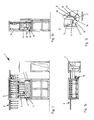
- FIG. 1 shows a cleaning device 1 in a basic position with eight juxtaposed cleaning places 2.
- Each cleaning station 2 includes a sleeve pot 3.
- the cleaning stations 2 are arranged on a common bench 4.
- the yarn sheaths 5 with the yarn residues to be removed are located on a transport unit 6. They are transported by this to the cleaning device 1 and positioned above the sleeve pots 3 in such a way that a yarn sleeve 5 is located above a sleeve pot 3.
- the cleaning stations 2 are connected to a common suction fan 7 ( FIG. 1b ), which is designed here as a radial fan.
- a flow velocity v2 ( Figure 3c ) realized in an intake passage 8.
- FIG. 1 a shows the cleaning device 1 in a side view.
- the sleeve pot 3 passes via a directly below the sleeve pot 3 arranged suction funnel 9 in the intake passage 8 via.
- the intake passage 8 has a deflection 10 in the form of a manifold, which extends in this embodiment over the entire length of the intake passage 8 and in this embodiment also forms this quasi. It is also possible to provide the intake duct 8 with straight sections in front of and behind the deflection 10. In this case, the intake passage 8 may be made in one piece or in several pieces. Under an intake passage in the context of the invention is that flow path to be understood, which extends between a suction funnel and a collecting container.
- the Figure 1c shows an enlarged section of the intake passage 8 with suction funnel 9 and sleeve pot 3 of FIG. 1 a.
- the deflection 10 has a Garnstrom Chemistry 11, which is located inside the peripheral portion 14 of the reverser 10. It is the area with the smallest radius of curvature R. In this yarn contact surface 11 opens a suction tube 12, which is provided for receiving the yarn residues from the intake passage 8.
- the intake ports 8 of the cleaning stations 2 are connected to a common receptacle 16.
- the suction pipes 12 are also connected to a common collecting container 15.
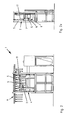
- the bank 4 is vertically displaced with the cleaning stations 2 between a basic position (below) and a cleaning position (above).
- a drive unit 19 in conjunction with an envelope drive, the bank 4 is vertically displaced with the cleaning stations 2 between a basic position (below) and a cleaning position (above).
- an upper end 17 of the sleeve pots 3 is located at about half the height of the yarn tubes 5.
- middle position takes a break, which may for example be between 1 to 4 seconds before the bank 4 is moved to the cleaning stations 2 in the cleaning position
- FIG. 3 In the middle position, the yarn tubes 5 are half in the sleeve pot. 3
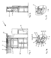
- the sleeve pots 3 are completely slipped over the yarn tubes 5.
- vacuum source is switched on.
- the diameter D1 of the suction tube 12 in the connection region of suction tube 12 and deflection 10 is smaller than the diameter D2 of the deflection 10.
- the suction tube 12 has in this embodiment a constant diameter D1, but it is also possible the suction tube 12 with varying over its length Diameters to provide. As a result, a higher flow velocity v1 is achieved in the intake manifold 12 via the vacuum source than the flow velocity v2 generated by the suction fan 7 in the intake duct 8.
- the yarn residues Due to the flow velocity v 2 in the intake channel 8, the yarn residues are guided out of the tube pot 3 into the suction funnel 9 and subsequently into the intake channel 8. In the intake channel 8, the yarn residues are due to the flow of yarn to the Garnstrom matters 11 on the inner side 13 of the intake passage 8 in the region of the deflection 10. The opening into the Garnstrom constitutional 11 intake manifold 12 pulls the yarn residues from the intake passage 8 in the intake manifold 12 through the higher flow velocity v1.
- the high flow velocity v1 and the air turbulence in the transition region between the intake duct 8 and suction tube 12 dissolve the yarn residues during their pulling into the suction tube 12 into individual fibers.
- the thus dissolved yarn residues are passed into a collecting vessel 15 adjoining the suction pipe 12. From there they can be fed to the yarn production. Yarn residues, which can not be drawn in by the suction tube 12, pass into a collecting container 16 adjoining the intake channel 8.
- the cleaning stations 2 are kept in the cleaning position until all yarn residues are completely removed from the yarn sleeve 2.
- Bank 4 is moved back to the basic position.
- the vacuum source is switched off, whereby the suction fan 7 can remain in operation.
- the cleaned yarn tubes 5 are transported out of the cleaning device 1 via the transport unit 6.
- new yarn tubes 5 with yarn residues are transported into the cleaning device 1, FIG. 1 ,
Landscapes
- Spinning Or Twisting Of Yarns (AREA)
Abstract
Description
- Die Erfindung betrifft eine Reinigungsvorrichtung sowie ein Verfahren zum Entfernen und Auflösen von Garnsresten von Garnhülsen.
- Die in der Textilherstellung zur Verarbeitung notwendigen Garne werden auf Garnhülsen aufgewickelt, die auch als Spulen bezeichnet werden. Während des Spinnvorgangs oder der Herstellung von Textilien wird das Garn von den Garnhülsen abgewickelt. Aus handhabungstechnischen Gründen werden diese Garnhülsen während eines Produktionsprozesses durch volle Garnhülsen ersetzt, bevor das Garn einer Garnhülse restlos aufgebraucht ist. Vor dem erneuten Aufwickeln der Garnhülsen werden die Garnreste von der Garnhülse entfernt. Die Garnreste werden aufgelöst und möglichst zu neuem Garn gesponnen.
- Die
EP 0 548 572 B1 offenbart eine Vorrichtung zum Entfernen von Restgarn, bei welcher das Restgarn von der Spule abgesaugt wird. Dazu wird ein Gebläse oberhalb der Spule angeordnet und die Garnreste werden von der Garnhülse geblasen. Diese Garnreste werden über einen Trichter, welcher unterhalb der Garnhülse angeordnet ist in einen Auffangbehälter abgesaugt. - Um das Garn dem Produktionsprozess wieder zuzuführen, muss es nach dem Ablösen von der Garnhülse soweit aufgelöst werden, dass die einzelnen Fasern wieder zu einem Garn gesponnen werden können. Ein einfaches Abblasen oder Absaugen des Garns reicht hierzu nicht aus, so dass ein zusätzlicher Arbeitsschritt zum Auflösen des Garns notwendig ist.
- Der Erfindung liegt ausgehend vom Stand der Technik die Aufgabe zu Grunde, eine Vorrichtung zum Entfernen der Garnreste von Garnhülsen aufzuzeigen, durch welche die Garnreste sowohl von der Garnhülse entfernt werden als auch gleichzeitig aufgelöst werden können. Weiterhin zielt die Erfindung auf ein Verfahren zum Entfernen von Garnresten von Garnhülsen ab.
- Die Lösung des gegenständlichen Teils der Aufgabe besteht in einer Reinigungsvorrichtung gemäß den Merkmalen des Patentanspruchs 1.
- Der verfahrensmäßige Teil der Aufgabe besteht nach der Erfindung in einem Verfahren gemäß den Maßnahmen des Patentanspruchs 8.
- Weitere Ausführungen der erfindungsgemäßen Reinigungsvorrichtung sind Gegenstand der Unteransprüche 2 bis 7.
- Weitere erfindungsgemäße Maßnahmen des Verfahrens sind Gegenstand der Unteransprüche 9 bis 13.
- Die Reinigungsvorrichtung zum Entfernen der Garnreste von Garnhülsen umfasst mindestens einen Reinigungsplatz mit einem Hülsentopf, welcher zur Aufnahme einer Garnhülse vorgesehen ist. Am Hülsentopf ist ein Saugtrichter vorgesehen, über welchen die angesaugten Garnreste in einen Ansaugkanal geleitet werden. Dabei kann sich der Ansaugkanal direkt an den Saugtrichter anschließen.
- Der Ansaugkanal weist eine Umlenkung, quasi in Form eines Krümmers mit einer Garnanlagefläche auf. Dabei ist die Garnanlagefläche an der Innenseite des umfangsseitigen Bereichs der Umlenkung angeordnet, welcher den kleinsten Krümmungsradius aufweist. Der Winkelbereich der Umlenkung ist vorzugsweise größer als 90° und kann insbesondere zwischen 90° und 145° liegen. Vorzugsweise beträgt der Winkel 135°. In die Garnanlagefläche mündet ein Saugrohr über welches ein Garnrest aus dem Ansaugkanal herausgesogen wird. Der innere Durchmesser des Saugrohres im Anschlussbereich ist kleiner als der innere Durchmesser des Ansaugkanals im Bereich der Umlenkung. Vorzugsweise liegt das Verhältnis des inneren Durchmessers der Umlenkung zum inneren Durchmesser des Saugrohres zwischen 1/10 bis 1/5.
- Bevorzugt sind mehrere Reinigungsplätze an ein gemeinsames Sauggebläse angeschlossen. Die durch das Sauggebläse im Ansaugkanal erzeugte Strömungsgeschwindigkeit soll dabei kleiner sein als die Strömungsgeschwindigkeit im Saugrohr.
- Zum Erreichen dieser für das erfindungsgemäße Verfahren wesentlich höheren Strömungsgeschwindigkeiten im Saugrohr, ist dieses an eine Unterdruckquelle angeschlossen. Durch die Unterdruckquelle und den kleineren inneren Durchmesser des Saugrohrs im Vergleich zum inneren Durchmesser der Umlenkung wird im Saugrohr die höhere Strömungsgeschwindigkeit erzielt.
- Bei dem erfindungsgemäßen Verfahren zum Entfernen von Garnresten von Garnhülsen werden die Hülsentöpfe mit einem offenen Ende über die Garnhülsen gestülpt. Dazu wird eine Bank mit vorzugsweise mehreren Reinigungsplätzen beispielsweise mittels eines kraft- oder reibschlüssigen Hülltriebes so weit verlagert, dass die Hülsentöpfe vollständig über die Garnhülsen gestülpt werden. Die Vorrichtung befindet sich dann in einer Reinigungsstellung. Beim Start der Bewegung wird die an das Saugrohr angeschlossene Unterdruckquelle zugeschaltet. Über ein an die Reinigungsplätze angeschlossenes gemeinsames Sauggebläse werden die Garnreste von der Garnhülse über einen Saugtrichter in einen Ansaugkanal geleitet. Dort legen sich die Garnreste an die Garnanlagefläche der Umlenkung an und werden über das in die Garnanlagefläche mündende Saugrohr angesogen und in einen Auffangbehälter geleitet.
- Der Ansaugkanal kann dabei direkt an den Saugtrichter angeschlossen sein. Das Sauggebläse ist vorzugsweise in Dauerbetrieb geschaltet.
- Ein wesentliches Merkmal der Erfindung ist die Garnführung innerhalb der Umlenkung. Die hierfür vorgesehen Garnanlagefläche befindet sich innenseitig des umfangsseitigen Bereichs der Umlenkung mit dem kleinsten Krümmungsradius. Dieser Bereich weist gleichzeitig die höchste Strömungsgeschwindigkeit in der Umlenkung auf. Bedingt durch die Strömungsgeschwindigkeit und deren Verteilung im Ansaugkanal legt sich der Garnrest an die Garnanlagefläche an der Innenseite der Wand der Umlenkung im Ansaugkanal an. Erfindungsgemäß mündet ein Saugrohr in die Garnanlagefläche, um den Garnrest von dort zuverlässig einzusaugen.
- Die hohe Strömungsgeschwindigkeit und die im Verbindungsbereich von Saugrohr und Umlenkung entstehenden Luftverwirbelungen bewirken, dass die Garnreste innerhalb des Saurohrs in Fasern aufgelöst werden.
- Durch das Saugrohr gelangen die Fasern in einen Auffangbehälter, von dem aus sie wieder der Garnherstellung zugeführt werden.
- Für den Fall, dass die Garnreste nicht vollständig in das Saugrohr hineingezogen werden, ist der Ansaugkanal ebenfalls mit einem Auffangbehälter versehen.
- Die Reinigungsplätze werden solange in Reinigungsstellung gehalten, bis alle Garnreste vollständig von der Garnhülse entfernt sind. Dies kann bereits innerhalb von 2 bis 4 Sekunden der Fall sein.
- Nach dem Entfernen der Garnreste werden die Garnhülsen freigegeben, indem die Bank mit den Reinigungsplätzen in eine Grundstellung verlagert wird.
- Es ist verfahrenstechnisch von Vorteil, wenn während des Verlagerns der Reinigungsplätze von einer Grundstellung in die Reinigungsstellung eine Haltepause eingelegt wird, sobald die Hülsentöpfe teilweise über die Garnhülsen gestülpt sind. Vorzugweise wird die Verlagerung gestoppt, wenn sich ein oberes Ende des Hülsentopfes auf halber Höhe der Garnhülsen befindet. Die Haltedauer kann zwischen 1 bis 3 Sekunden betragen.
- Neben einer bevorzugt synchronen Verlagerung der Reinigungsplätze ist es ebenfalls möglich, diese unabhängig voneinander in die verschiedenen Stellungen zu verfahren und dort zu halten. Ebenso kann die Haltedauer zwischen den einzelnen Reinigungsplätzen variieren.
- Die erfindungsgemäße Reinigungsvorrichtung ermöglicht es, Garnreste in einem Schritt zuverlässig und effizient von den Garnhülsen zu entfernen und zudem noch effektiv in ihre Faserbestandteile aufzulösen, so dass diese wieder zur Garnherstellung eingesetzt werden können.
- Das erfindungsgemäße Verfahren und die Erfindung werden anhand der nachfolgenden Zeichnungen näher beschrieben. Es zeigen:
- Figur 1
- die Reinigungsvorrichtung in der Grundstellung;
- Figur 1 a
- Seitenansicht der Reinigungsvorrichtung aus
Figur 1 ; - Figur 1 b
- Aufsicht der Reinigungsvorrichtung aus
Figur 1 ; - Figur 1 c
- Vergrößerung des Ausschnitts A der
Figur 1 a; - Figur 2
- die Reinigungsvorrichtung in der Mittelstellung;
- Figur 2a
- Seitenansicht der Reinigungsvorrichtung aus
Figur 2 ; - Figur 3
- die Reinigungsvorrichtung in der Reinigungsstellung
- Figur 3a
- Seitenansicht der Reinigungsvorrichtung aus
Figur 3 und - Figur 3b und 3c
- Vergrößerung des Ausschnitts A der
Figur 3a . -
Figur 1 zeigt eine Reinigungsvorrichtung 1 in einer Grundstellung mit acht nebeneinander angeordneten Reinigungsplätzen 2. Zu jedem Reinigungsplatz 2 gehört ein Hülsentopf 3. Die Reinigungsplätze 2 sind auf einer gemeinsamen Bank 4 angeordnet. - Die Garnhülsen 5 mit den zu entfernenden Garnresten befinden sich an einer Transporteinheit 6. Sie werden von dieser zur Reinigungsvorrichtung 1 transportiert und oberhalb der Hülsentöpfe 3 so positioniert, dass sich jeweils eine Garnhülse 5 über einem Hülsentopf 3 befindet.
- Die Reinigungsplätze 2 sind an ein gemeinsames Sauggebläse 7 angeschlossen (
Figur 1b ), welches hier als Radialgebläse ausgeführt ist. Über das in Dauerbetrieb geschaltete Sauggebläse 7 wird eine Strömungsgeschwindigkeit v2 (Figur 3c ) in einem Ansaugkanal 8 realisiert. -
Figur 1 a zeigt die Reinigungsvorrichtung 1 in einer Seitenansicht. Der Hülsentopf 3 geht über einen direkt unterhalb des Hülsentopfes 3 angeordneten Saugtrichter 9 in den Ansaugkanal 8 über. Der Ansaugkanal 8 weist eine Umlenkung 10 in Form eines Krümmers auf, der sich bei diesem Ausführungsbeispiel über die gesamte Länge des Ansaugkanals 8 erstreckt und in diesem Ausführungsbeispiels diesen auch quasi bildet. Ebenso ist es möglich, den Ansaugkanal 8 mit geraden Abschnitten vor und hinter der Umlenkung 10 zu versehen. Dabei kann der Ansaugkanal 8 einstückig oder mehrstückig ausgeführt sein. Unter einem Ansaugkanal im Sinne der Erfindung ist derjenige Strömungsweg zu verstehen, der sich zwischen einem Saugtrichter und einem Auffangbehälter erstreckt. - Die
Figur 1c zeigt einen vergrößerten Ausschnitt des Ansaugkanals 8 mit Saugtrichter 9 und Hülsentopf 3 derFigur 1 a. Die Umlenkung 10 weist eine Garnanlagefläche 11 auf, die sich innenseitig des umfangsseitigen Bereichs 14 der Umlenkung 10 befindet. Es ist der Bereich mit dem kleinsten Krümmungsradius R. In diese Garnanlagefläche 11 mündet ein Saugrohr 12, welches zur Aufnahme der Garnreste aus dem Ansaugkanal 8 vorgesehen ist. - Die Ansaugkanäle 8 der Reinigungsplätze 2 sind an einen gemeinsamen Auffangbehälter 16 angeschlossen.
- Die Saugrohre 12 sind ebenfalls an einen gemeinsamen Auffangbehälter 15 angeschlossen.
- Mittels einer Antriebseinheit 19 in Verbindung mit einem Hülltrieb wird die Bank 4 mit den Reinigungsplätzen 2 zwischen einer Grundstellung (unten) und einer Reinigungstellung (oben) vertikal verlagert. Zunächst allerdings nur soweit, dass ein oberes Ende 17 der Hülsentöpfe 3 sich auf etwa halber Höhe der Garnhülsen 5 befindet. In dieser in
Figur 2 dargestellten Mittelstellung erfolgt eine Haltepause, die beispielsweise zwischen 1 bis 4 Sekunden liegen kann, bevor die Bank 4 mit den Reinigungsplätzen 2 in die Reinigungsstellung verlagert wird,Figur 3 . In der Mittelstellung befinden sich die Garnhülsen 5 zur Hälfte im Hülsentopf 3. - In der Reinigungsstellung (
Figuren 3 bis 3c ) sind die Hülsentöpfe 3 vollständig über die Garnhülsen 5 gestülpt. Beim Start der Aufwärtsbewegung wird eine über einen Anschluss 18 an das Saugrohr 12 angeschlossene Unterdruckquelle zugeschaltet. Der Durchmesser D1 des Saugrohres 12 im Verbindungsbereich von Saugrohr 12 und Umlenkung 10 ist kleiner als der Durchmesser D2 der Umlenkung 10. Das Saugrohr 12 weist in dieser Ausführung einen konstanten Durchmesser D1 auf, es ist jedoch ebenso möglich das Saugrohr 12 mit über seine Länge variierenden Durchmessern zu versehen. Dadurch wird im Saugrohr 12 über die Unterdruckquelle eine höhere Strömungsgeschwindigkeit v1 erzielt, als die durch das Sauggebläse 7 im Ansaugkanal 8 erzeugte Strömungsgeschwindigkeit v2. - Durch die Strömungsgeschwindigkeit v2 im Ansaugkanal 8 werden die Garnreste aus dem Hülsentopf 3 in den Saugtrichter 9 und im Anschluss daran in den Ansaugkanal 8 geleitet. Im Ansaugkanal 8 legen sich die Garnreste strömungsbedingt an die Garnanlagefläche 11 an der Innenseite 13 des Ansaugkanals 8 im Bereich der Umlenkung 10. Das in die Garnanlagefläche 11 mündende Saugrohr 12 zieht durch die höhere Strömungsgeschwindigkeit v1 die Garnreste aus dem Ansaugkanal 8 in das Saugrohr 12.
- Die hohe Strömungsgeschwindigkeit v1 und die Luftverwirbelungen im Übergangbereich zwischen Ansaugkanal 8 und Saugrohr 12 lösen die Garnreste während es Hineinziehens in das Saugrohr 12 in einzelne Fasern auf.
- Die so aufgelösten Garnreste werden in einen sich an das Saugrohr 12 anschließenden Auffangbehälter 15 geleitet. Von dort aus können sie der Garnherstellung zugeführt werden. Garnreste, die von dem Saugrohr 12 nicht eingezogen werden können, gelangen in einen sich an den Ansaugkanal 8 anschließenden Auffangbehälter 16.
- Die Reinigungsplätze 2 werden solange in Reinigungsstellung gehalten, bis alle Garnreste vollständig von der Garnhülse 2 entfernt sind.
- Anschließend wird die Bank 4 wieder in die Grundstellung zurück verlagert. Die Unterdruckquelle wird abgeschaltet, wobei das Sauggebläse 7 in Betrieb bleiben kann. Die gereinigten Garnhülsen 5 werden über die Transporteinheit 6 aus der Reinigungsvorrichtung 1 hinaustransportiert. Gleichzeitig werden neue Garnhülsen 5 mit Garnresten in die Reinigungsvorrichtung 1 hineintransportiert,
Figur 1 . -
- 1 -
- Reinigungsvorrichtung
- 2 -
- Reinigungsplatz
- 3 -
- Hülsentopf
- 4 -
- Bank
- 5 -
- Garnhülse
- 6 -
- Transporteinheit
- 7 -
- Sauggebläse
- 8 -
- Ansaugkanal
- 9 -
- Saugtrichter
- 10 -
- Umlenkung
- 11 -
- Garnanlagefläche
- 12 -
- Saugrohr
- 13 -
- Innenseite
- 14 -
- umfangsseitiger Bereich
- 15 -
- Auffangbehälter
- 16 -
- Auffangbehälter
- 17 -
- oberes Ende
- 18 -
- Anschluss für eine Unterdruckquelle
- 19 -
- Antriebseinheit
- 20 -
- leere Garnhülse
- R -
- Krümmungsradius
- D1 -
- Durchmesser Saugrohr
- D2 -
- Durchmesser Umlenkung
- V1 -
- Strömungsgeschwindigkeit im Saugrohr
- V2 -
- Strömungsgeschwindigkeit im Ansaugkanal
Claims (13)
- Reinigungsvorrichtung zum Entfernen von Garnresten von Garnhülsen (5) mit wenigstens einem Reinigungsplatz (2) für je eine Garnhülse (5), wobei jeder Reinigungsplatz (2) einen Hülsentopf (3) zur Aufnahme einer Garnhülse (5) umfasst und wobei ein Saugtrichter (9) an dem Hülsentopf (3) dafür vorgesehen ist, angesaugte Garnreste in einen Ansaugkanal (8) zu leiten, dadurch gekennzeichnet, dass der Ansaugkanal (8) eine Umlenkung (10) mit einer Garnanlagefläche (11) aufweist, wobei in die Garnanlagefläche (11) ein Saugrohr (12) zum Ansaugen der Garnreste mündet.
- Reinigungsvorrichtung nach Anspruch 1, dadurch gekennzeichnet, dass die Garnanlagefläche (11) an einer Innenseite (13) des umfangsseitigen Bereichs (14) der Umlenkung (10) angeordnet ist, wobei die Umlenkung (10) im Bereich der Garnanlagefläche (11) seinen kleinsten Krümmungsradius (R) aufweist.
- Reinigungsvorrichtung nach Anspruch 1 und 2, dadurch gekennzeichnet, dass eine Strömungsgeschwindigkeit (v1) im Saugrohr (12) größer ist als eine Strömungsgeschwindigkeit (v2) in der Umlenkung (10).
- Reinigungsvorrichtung nach einem der Ansprüche 1 bis 3, dadurch gekennzeichnet, dass ein innerer Durchmesser (D2) der Umlenkung (10) größer ist als ein innerer Durchmesser (D1) des Saugrohres (12).
- Reinigungsvorrichtung nach einem der Ansprüche 1 bis 4, dadurch gekennzeichnet, dass mehrere Reinigungsplätze (2) an ein gemeinsames Sauggebläse (7) angeschlossen sind.
- Reinigungsvorrichtung nach einem der Ansprüche 1 bis 5, dadurch gekennzeichnet, dass sich die Umlenkung (10) über einen Winkelbereich zwischen 90° und 145° erstreckt.
- Reinigungsvorrichtung nach einem der Ansprüche 1 bis 6, dadurch gekennzeichnet, dass der wenigstens eine Reinigungsplatz (2) relativ zu einer Garnhülse (5) verlagerbar ist, um den Hülsentopf (3) über die Garnhülse (5) zu stülpen.
- Verfahren zum Entfernen von Garnresten von Garnhülsen (5) mit folgenden Schritten:a) Hülsentöpfe (3) einer Reinigungsvorrichtung (1) werden über Garnhülsen (5) gestülpt,b) Garnreste werden in einen Saugtrichter (9) gesaugt und in einen Ansaugkanal (8) geleitet,c) die Garnreste legen sich an eine Garnanlagefläche (11) in einer Umlenkung (10) des Ansaugkanals (8),d) die Garnreste werden von einem Saugrohr (12), das in die Garnanlagefläche (11) mündet, angesogen, in einzelne Fasern aufgelöst und in einen Auffangbehälter (15) geleitet,e) Freigabe der Garnhülse (5).
- Verfahren nach Anspruch 9, dadurch gekennzeichnet, dass beim Verlagern der Reinigungsplätze (2) von einer Grundstellung in eine Reinigungsstellung eine Haltepause erfolgt, wobei der Hülsentopf (3) während der Haltepause in einer teilweise über die Garnhülse (5) gestülpten Position gehalten wird.
- Verfahren nach Anspruch 8 oder 9, dadurch gekennzeichnet, dass die Haltepause erfolgt, wenn der Hülsentopf (3) zur Hälfte über die Garnhülse (5) gestülpt ist.
- Verfahren nach einem der Ansprüche 9 bis 10, dadurch gekennzeichnet, dass die Hülsentöpfe (3) in der Reinigungsstellung vollständig über die Garnhülsen (5) gestülpt sind und dort für 2 bis 4 Sekunden gehalten werden.
- Verfahren nach einem der Ansprüche 9 bis 11, dadurch gekennzeichnet, dass die Strömungsgeschwindigkeit (v1) im Saugrohr (12) in der Reinigungsstellung durch Zuschaltung einer Unterdruckquelle gegenüber der Strömungsgeschwindigkeit (v2) im Ansaugkanal (8) im Bereich der Umlenkung (10) erhöht wird und die Unterdruckquelle in der Grundstellung abgeschaltet wird.
- Verfahren nach den Ansprüchen 8 bis 12, dadurch gekennzeichnet, dass die Garnhülsen (5) mit einer Transporteinheit (6) in die Reinigungsvorrichtung (1) transportiert werden.
Applications Claiming Priority (1)
| Application Number | Priority Date | Filing Date | Title |
|---|---|---|---|
| DE200810058540 DE102008058540A1 (de) | 2008-11-21 | 2008-11-21 | Reinigungsvorrichtung und Verfahren zum Entfernen von Garnresten von Garnhülsen |
Publications (3)
| Publication Number | Publication Date |
|---|---|
| EP2189409A2 true EP2189409A2 (de) | 2010-05-26 |
| EP2189409A3 EP2189409A3 (de) | 2012-03-28 |
| EP2189409B1 EP2189409B1 (de) | 2013-06-05 |
Family
ID=41698515
Family Applications (1)
| Application Number | Title | Priority Date | Filing Date |
|---|---|---|---|
| EP20090014485 Not-in-force EP2189409B1 (de) | 2008-11-21 | 2009-11-20 | Reinigungsvorrichtung und Verfahren zum Entfernen von Garnresten von Garnhülsen |
Country Status (2)
| Country | Link |
|---|---|
| EP (1) | EP2189409B1 (de) |
| DE (1) | DE102008058540A1 (de) |
Cited By (1)
| Publication number | Priority date | Publication date | Assignee | Title |
|---|---|---|---|---|
| WO2019215024A1 (de) * | 2018-05-08 | 2019-11-14 | Dahmen Textilmaschinen Gmbh | Spulenreinigungseinheit |
Families Citing this family (1)
| Publication number | Priority date | Publication date | Assignee | Title |
|---|---|---|---|---|
| CN106081740B (zh) * | 2016-08-09 | 2019-09-10 | 广东溢达纺织有限公司 | 自动除废纱机 |
Citations (1)
| Publication number | Priority date | Publication date | Assignee | Title |
|---|---|---|---|---|
| EP0548572B1 (de) | 1991-12-26 | 1995-09-20 | Murao And Company Limited | Vorrichtung zum Entfernen von Garnresten für unterschiedliche Vorgarnspulenqualitäten |
Family Cites Families (2)
| Publication number | Priority date | Publication date | Assignee | Title |
|---|---|---|---|---|
| JPH02289135A (ja) * | 1989-04-25 | 1990-11-29 | Howa Mach Ltd | 紡機の清掃装置 |
| DE102004024818A1 (de) * | 2004-05-17 | 2005-12-15 | Saurer Gmbh & Co. Kg | Entfernen von Vorgarnresten von Klettbändern an Vorgarnspulen |
-
2008
- 2008-11-21 DE DE200810058540 patent/DE102008058540A1/de not_active Withdrawn
-
2009
- 2009-11-20 EP EP20090014485 patent/EP2189409B1/de not_active Not-in-force
Patent Citations (1)
| Publication number | Priority date | Publication date | Assignee | Title |
|---|---|---|---|---|
| EP0548572B1 (de) | 1991-12-26 | 1995-09-20 | Murao And Company Limited | Vorrichtung zum Entfernen von Garnresten für unterschiedliche Vorgarnspulenqualitäten |
Cited By (1)
| Publication number | Priority date | Publication date | Assignee | Title |
|---|---|---|---|---|
| WO2019215024A1 (de) * | 2018-05-08 | 2019-11-14 | Dahmen Textilmaschinen Gmbh | Spulenreinigungseinheit |
Also Published As
| Publication number | Publication date |
|---|---|
| DE102008058540A1 (de) | 2010-05-27 |
| EP2189409A3 (de) | 2012-03-28 |
| EP2189409B1 (de) | 2013-06-05 |
Similar Documents
| Publication | Publication Date | Title |
|---|---|---|
| EP2620532B1 (de) | Luftspinnmaschine mit einem Reinigungsorgan sowie Verfahren zum Reinigen der Wirbelkammer einer Luftspinnmaschine | |
| DE102005022187A1 (de) | Anspinnverfahren an einer Luftspinnmaschine sowie Spinnvorrichtung und Luftspinnmaschine | |
| DE102011053813A1 (de) | Spinnmaschine sowie Verfahren zum Abführen eines Endabschnitts eines Garns an einer Spinnmaschine vor einem anschließenden Anspinnvorgang | |
| DE102017116893A1 (de) | Fadenführungseinheit, Offenend-Spinnmaschine und Verfahren zum Betreiben einer Spinnstelle | |
| EP2189409B1 (de) | Reinigungsvorrichtung und Verfahren zum Entfernen von Garnresten von Garnhülsen | |
| EP3771756B1 (de) | Spinnmaschine mit einer vielzahl nebeneinander angeordneter arbeitsstellen und einer verfahrbaren wartungseinrichtung mit einem pneumatischen arbeitsorgan sowie verfahren zum versorgen des pneumatischen arbeitsorgans mit unterdruck | |
| DE2543767A1 (de) | Verfahren und vorrichtung zum pneumatischen abloesen und ansaugen eines gebrochenen fadenendes | |
| EP1217109A2 (de) | Spinnvorrichtung | |
| WO2018228864A1 (de) | Arbeitsstelle einer luftspinnmaschine sowie verfahren zum öffnen einer spinndüse | |
| DE19648561A1 (de) | Absaugeinrichtung an einer Textilmaschine | |
| DE3813720C2 (de) | ||
| CH713499A2 (de) | Luftspinnmaschine zur Herstellung eines Garns aus einem strangförmigen Faserverband. | |
| DE4221348A1 (de) | Spulen- und huelsentransportvorrichtung fuer eine spulmaschine | |
| DE102020110991A1 (de) | Verfahren zum Trennen eines aus einer Spinnkanne an eine Spinnstelle einer Spinnmaschine gelieferten Faserbandes sowie Spinnmaschine | |
| EP3663445A1 (de) | Spinndüse sowie verfahren zum reinigen derselben | |
| EP0310906A1 (de) | Verfahren und Vorrichtung zum Einbringen eines Vorgarnes in ein Streckwerk einer Textilmaschine | |
| DE102020000467A1 (de) | Vorrichtung zum Abziehen und Aufwickeln synthetischer Fäden | |
| DE3908463A1 (de) | Vorrichtung zum zwischenspeichern eines doppelfadens | |
| DE3416456C2 (de) | Verfahren und Vorrichtung zur Inbetriebnahme einer Friktionsspinnmaschine | |
| EP0595035A1 (de) | Vorrichtung zum Abtrennen von Schleppfäden von Textilspulen | |
| DE2437857A1 (de) | Vorrichtung zur aufnahme des endes eines faserbandes oder fadens | |
| DE3825327A1 (de) | Vorrichtung und verfahren zum speichern eines fadens | |
| LU501576B1 (de) | Luftspinnvorrichtung sowie Verfahren zur Oberflächenbehandlung innerhalb einer Luftspinnvorrichtung | |
| EP3790826A1 (de) | Spulenreinigungseinheit | |
| WO2005115897A1 (de) | Entfernen von vorgarnresten von klettbändern an vorgarnspulen |
Legal Events
| Date | Code | Title | Description |
|---|---|---|---|
| PUAI | Public reference made under article 153(3) epc to a published international application that has entered the european phase |
Free format text: ORIGINAL CODE: 0009012 |
|
| AK | Designated contracting states |
Kind code of ref document: A2 Designated state(s): AT BE BG CH CY CZ DE DK EE ES FI FR GB GR HR HU IE IS IT LI LT LU LV MC MK MT NL NO PL PT RO SE SI SK SM TR |
|
| AX | Request for extension of the european patent |
Extension state: AL BA RS |
|
| PUAL | Search report despatched |
Free format text: ORIGINAL CODE: 0009013 |
|
| AK | Designated contracting states |
Kind code of ref document: A3 Designated state(s): AT BE BG CH CY CZ DE DK EE ES FI FR GB GR HR HU IE IS IT LI LT LU LV MC MK MT NL NO PL PT RO SE SI SK SM TR |
|
| AX | Request for extension of the european patent |
Extension state: AL BA RS |
|
| RIC1 | Information provided on ipc code assigned before grant |
Ipc: B65H 73/00 20060101AFI20120223BHEP |
|
| 17P | Request for examination filed |
Effective date: 20120914 |
|
| GRAP | Despatch of communication of intention to grant a patent |
Free format text: ORIGINAL CODE: EPIDOSNIGR1 |
|
| GRAS | Grant fee paid |
Free format text: ORIGINAL CODE: EPIDOSNIGR3 |
|
| GRAA | (expected) grant |
Free format text: ORIGINAL CODE: 0009210 |
|
| AK | Designated contracting states |
Kind code of ref document: B1 Designated state(s): AT BE BG CH CY CZ DE DK EE ES FI FR GB GR HR HU IE IS IT LI LT LU LV MC MK MT NL NO PL PT RO SE SI SK SM TR |
|
| REG | Reference to a national code |
Ref country code: GB Ref legal event code: FG4D Free format text: NOT ENGLISH |
|
| REG | Reference to a national code |
Ref country code: CH Ref legal event code: EP |
|
| REG | Reference to a national code |
Ref country code: AT Ref legal event code: REF Ref document number: 615569 Country of ref document: AT Kind code of ref document: T Effective date: 20130615 |
|
| REG | Reference to a national code |
Ref country code: IE Ref legal event code: FG4D Free format text: LANGUAGE OF EP DOCUMENT: GERMAN |
|
| REG | Reference to a national code |
Ref country code: DE Ref legal event code: R096 Ref document number: 502009007276 Country of ref document: DE Effective date: 20130801 |
|
| PG25 | Lapsed in a contracting state [announced via postgrant information from national office to epo] |
Ref country code: ES Free format text: LAPSE BECAUSE OF FAILURE TO SUBMIT A TRANSLATION OF THE DESCRIPTION OR TO PAY THE FEE WITHIN THE PRESCRIBED TIME-LIMIT Effective date: 20130916 Ref country code: GR Free format text: LAPSE BECAUSE OF FAILURE TO SUBMIT A TRANSLATION OF THE DESCRIPTION OR TO PAY THE FEE WITHIN THE PRESCRIBED TIME-LIMIT Effective date: 20130906 Ref country code: SI Free format text: LAPSE BECAUSE OF FAILURE TO SUBMIT A TRANSLATION OF THE DESCRIPTION OR TO PAY THE FEE WITHIN THE PRESCRIBED TIME-LIMIT Effective date: 20130605 Ref country code: FI Free format text: LAPSE BECAUSE OF FAILURE TO SUBMIT A TRANSLATION OF THE DESCRIPTION OR TO PAY THE FEE WITHIN THE PRESCRIBED TIME-LIMIT Effective date: 20130605 Ref country code: NO Free format text: LAPSE BECAUSE OF FAILURE TO SUBMIT A TRANSLATION OF THE DESCRIPTION OR TO PAY THE FEE WITHIN THE PRESCRIBED TIME-LIMIT Effective date: 20130905 Ref country code: LT Free format text: LAPSE BECAUSE OF FAILURE TO SUBMIT A TRANSLATION OF THE DESCRIPTION OR TO PAY THE FEE WITHIN THE PRESCRIBED TIME-LIMIT Effective date: 20130605 Ref country code: SE Free format text: LAPSE BECAUSE OF FAILURE TO SUBMIT A TRANSLATION OF THE DESCRIPTION OR TO PAY THE FEE WITHIN THE PRESCRIBED TIME-LIMIT Effective date: 20130605 |
|
| REG | Reference to a national code |
Ref country code: NL Ref legal event code: VDEP Effective date: 20130605 |
|
| REG | Reference to a national code |
Ref country code: LT Ref legal event code: MG4D |
|
| PG25 | Lapsed in a contracting state [announced via postgrant information from national office to epo] |
Ref country code: PL Free format text: LAPSE BECAUSE OF FAILURE TO SUBMIT A TRANSLATION OF THE DESCRIPTION OR TO PAY THE FEE WITHIN THE PRESCRIBED TIME-LIMIT Effective date: 20130605 Ref country code: BG Free format text: LAPSE BECAUSE OF FAILURE TO SUBMIT A TRANSLATION OF THE DESCRIPTION OR TO PAY THE FEE WITHIN THE PRESCRIBED TIME-LIMIT Effective date: 20130905 Ref country code: HR Free format text: LAPSE BECAUSE OF FAILURE TO SUBMIT A TRANSLATION OF THE DESCRIPTION OR TO PAY THE FEE WITHIN THE PRESCRIBED TIME-LIMIT Effective date: 20130605 |
|
| PG25 | Lapsed in a contracting state [announced via postgrant information from national office to epo] |
Ref country code: LV Free format text: LAPSE BECAUSE OF FAILURE TO SUBMIT A TRANSLATION OF THE DESCRIPTION OR TO PAY THE FEE WITHIN THE PRESCRIBED TIME-LIMIT Effective date: 20130605 |
|
| PG25 | Lapsed in a contracting state [announced via postgrant information from national office to epo] |
Ref country code: EE Free format text: LAPSE BECAUSE OF FAILURE TO SUBMIT A TRANSLATION OF THE DESCRIPTION OR TO PAY THE FEE WITHIN THE PRESCRIBED TIME-LIMIT Effective date: 20130605 Ref country code: CZ Free format text: LAPSE BECAUSE OF FAILURE TO SUBMIT A TRANSLATION OF THE DESCRIPTION OR TO PAY THE FEE WITHIN THE PRESCRIBED TIME-LIMIT Effective date: 20130605 Ref country code: IS Free format text: LAPSE BECAUSE OF FAILURE TO SUBMIT A TRANSLATION OF THE DESCRIPTION OR TO PAY THE FEE WITHIN THE PRESCRIBED TIME-LIMIT Effective date: 20131005 Ref country code: PT Free format text: LAPSE BECAUSE OF FAILURE TO SUBMIT A TRANSLATION OF THE DESCRIPTION OR TO PAY THE FEE WITHIN THE PRESCRIBED TIME-LIMIT Effective date: 20131007 Ref country code: SK Free format text: LAPSE BECAUSE OF FAILURE TO SUBMIT A TRANSLATION OF THE DESCRIPTION OR TO PAY THE FEE WITHIN THE PRESCRIBED TIME-LIMIT Effective date: 20130605 |
|
| PG25 | Lapsed in a contracting state [announced via postgrant information from national office to epo] |
Ref country code: NL Free format text: LAPSE BECAUSE OF FAILURE TO SUBMIT A TRANSLATION OF THE DESCRIPTION OR TO PAY THE FEE WITHIN THE PRESCRIBED TIME-LIMIT Effective date: 20130605 Ref country code: RO Free format text: LAPSE BECAUSE OF FAILURE TO SUBMIT A TRANSLATION OF THE DESCRIPTION OR TO PAY THE FEE WITHIN THE PRESCRIBED TIME-LIMIT Effective date: 20130605 |
|
| PLBE | No opposition filed within time limit |
Free format text: ORIGINAL CODE: 0009261 |
|
| STAA | Information on the status of an ep patent application or granted ep patent |
Free format text: STATUS: NO OPPOSITION FILED WITHIN TIME LIMIT |
|
| PG25 | Lapsed in a contracting state [announced via postgrant information from national office to epo] |
Ref country code: DK Free format text: LAPSE BECAUSE OF FAILURE TO SUBMIT A TRANSLATION OF THE DESCRIPTION OR TO PAY THE FEE WITHIN THE PRESCRIBED TIME-LIMIT Effective date: 20130605 |
|
| 26N | No opposition filed |
Effective date: 20140306 |
|
| PG25 | Lapsed in a contracting state [announced via postgrant information from national office to epo] |
Ref country code: IT Free format text: LAPSE BECAUSE OF FAILURE TO SUBMIT A TRANSLATION OF THE DESCRIPTION OR TO PAY THE FEE WITHIN THE PRESCRIBED TIME-LIMIT Effective date: 20130605 |
|
| BERE | Be: lapsed |
Owner name: NEUENHAUSER MASCHINENBAU G.M.B.H. Effective date: 20131130 |
|
| REG | Reference to a national code |
Ref country code: DE Ref legal event code: R097 Ref document number: 502009007276 Country of ref document: DE Effective date: 20140306 |
|
| REG | Reference to a national code |
Ref country code: CH Ref legal event code: PL |
|
| GBPC | Gb: european patent ceased through non-payment of renewal fee |
Effective date: 20131120 |
|
| PG25 | Lapsed in a contracting state [announced via postgrant information from national office to epo] |
Ref country code: CH Free format text: LAPSE BECAUSE OF NON-PAYMENT OF DUE FEES Effective date: 20131130 Ref country code: LI Free format text: LAPSE BECAUSE OF NON-PAYMENT OF DUE FEES Effective date: 20131130 Ref country code: MC Free format text: LAPSE BECAUSE OF FAILURE TO SUBMIT A TRANSLATION OF THE DESCRIPTION OR TO PAY THE FEE WITHIN THE PRESCRIBED TIME-LIMIT Effective date: 20130605 |
|
| REG | Reference to a national code |
Ref country code: FR Ref legal event code: ST Effective date: 20140731 |
|
| REG | Reference to a national code |
Ref country code: IE Ref legal event code: MM4A |
|
| PG25 | Lapsed in a contracting state [announced via postgrant information from national office to epo] |
Ref country code: BE Free format text: LAPSE BECAUSE OF NON-PAYMENT OF DUE FEES Effective date: 20131130 |
|
| PG25 | Lapsed in a contracting state [announced via postgrant information from national office to epo] |
Ref country code: IE Free format text: LAPSE BECAUSE OF NON-PAYMENT OF DUE FEES Effective date: 20131120 |
|
| PG25 | Lapsed in a contracting state [announced via postgrant information from national office to epo] |
Ref country code: GB Free format text: LAPSE BECAUSE OF NON-PAYMENT OF DUE FEES Effective date: 20131120 Ref country code: FR Free format text: LAPSE BECAUSE OF NON-PAYMENT OF DUE FEES Effective date: 20131202 |
|
| PG25 | Lapsed in a contracting state [announced via postgrant information from national office to epo] |
Ref country code: SM Free format text: LAPSE BECAUSE OF FAILURE TO SUBMIT A TRANSLATION OF THE DESCRIPTION OR TO PAY THE FEE WITHIN THE PRESCRIBED TIME-LIMIT Effective date: 20130605 |
|
| PG25 | Lapsed in a contracting state [announced via postgrant information from national office to epo] |
Ref country code: CY Free format text: LAPSE BECAUSE OF FAILURE TO SUBMIT A TRANSLATION OF THE DESCRIPTION OR TO PAY THE FEE WITHIN THE PRESCRIBED TIME-LIMIT Effective date: 20130605 Ref country code: TR Free format text: LAPSE BECAUSE OF FAILURE TO SUBMIT A TRANSLATION OF THE DESCRIPTION OR TO PAY THE FEE WITHIN THE PRESCRIBED TIME-LIMIT Effective date: 20130605 |
|
| PG25 | Lapsed in a contracting state [announced via postgrant information from national office to epo] |
Ref country code: LU Free format text: LAPSE BECAUSE OF NON-PAYMENT OF DUE FEES Effective date: 20131120 Ref country code: HU Free format text: LAPSE BECAUSE OF FAILURE TO SUBMIT A TRANSLATION OF THE DESCRIPTION OR TO PAY THE FEE WITHIN THE PRESCRIBED TIME-LIMIT; INVALID AB INITIO Effective date: 20091120 Ref country code: MK Free format text: LAPSE BECAUSE OF FAILURE TO SUBMIT A TRANSLATION OF THE DESCRIPTION OR TO PAY THE FEE WITHIN THE PRESCRIBED TIME-LIMIT Effective date: 20130605 |
|
| PG25 | Lapsed in a contracting state [announced via postgrant information from national office to epo] |
Ref country code: MT Free format text: LAPSE BECAUSE OF FAILURE TO SUBMIT A TRANSLATION OF THE DESCRIPTION OR TO PAY THE FEE WITHIN THE PRESCRIBED TIME-LIMIT Effective date: 20130605 |
|
| REG | Reference to a national code |
Ref country code: AT Ref legal event code: MM01 Ref document number: 615569 Country of ref document: AT Kind code of ref document: T Effective date: 20141120 |
|
| PG25 | Lapsed in a contracting state [announced via postgrant information from national office to epo] |
Ref country code: AT Free format text: LAPSE BECAUSE OF NON-PAYMENT OF DUE FEES Effective date: 20141120 |
|
| PGFP | Annual fee paid to national office [announced via postgrant information from national office to epo] |
Ref country code: DE Payment date: 20181128 Year of fee payment: 10 |
|
| REG | Reference to a national code |
Ref country code: DE Ref legal event code: R119 Ref document number: 502009007276 Country of ref document: DE |
|
| PG25 | Lapsed in a contracting state [announced via postgrant information from national office to epo] |
Ref country code: DE Free format text: LAPSE BECAUSE OF NON-PAYMENT OF DUE FEES Effective date: 20200603 |