EP2188403B1 - Verfahren und schmelztauchveredelungsanlage zur bandstabilisierung eines zwischen abstreifdüsen der schmelztauchveredelungsanlage geführten, mit einer beschichtung versehenen bandes - Google Patents
Verfahren und schmelztauchveredelungsanlage zur bandstabilisierung eines zwischen abstreifdüsen der schmelztauchveredelungsanlage geführten, mit einer beschichtung versehenen bandes Download PDFInfo
- Publication number
- EP2188403B1 EP2188403B1 EP08801674A EP08801674A EP2188403B1 EP 2188403 B1 EP2188403 B1 EP 2188403B1 EP 08801674 A EP08801674 A EP 08801674A EP 08801674 A EP08801674 A EP 08801674A EP 2188403 B1 EP2188403 B1 EP 2188403B1
- Authority
- EP
- European Patent Office
- Prior art keywords
- strip
- hot
- distance
- detected
- width
- Prior art date
- Legal status (The legal status is an assumption and is not a legal conclusion. Google has not performed a legal analysis and makes no representation as to the accuracy of the status listed.)
- Active
Links
- 238000000034 method Methods 0.000 title claims abstract description 16
- 239000011248 coating agent Substances 0.000 title claims abstract description 15
- 238000000576 coating method Methods 0.000 title claims abstract description 15
- 230000000087 stabilizing effect Effects 0.000 title abstract description 13
- 238000003618 dip coating Methods 0.000 title abstract description 9
- 230000008569 process Effects 0.000 title abstract description 3
- 230000006641 stabilisation Effects 0.000 claims abstract description 47
- 229910000831 Steel Inorganic materials 0.000 claims abstract description 13
- 239000010959 steel Substances 0.000 claims abstract description 13
- 230000010355 oscillation Effects 0.000 claims description 6
- 238000009826 distribution Methods 0.000 claims description 5
- 230000008859 change Effects 0.000 claims description 4
- 238000005259 measurement Methods 0.000 claims description 4
- 230000003019 stabilising effect Effects 0.000 claims 5
- 238000011105 stabilization Methods 0.000 abstract description 42
- 230000000694 effects Effects 0.000 description 19
- 238000009499 grossing Methods 0.000 description 6
- 230000008901 benefit Effects 0.000 description 3
- 238000013016 damping Methods 0.000 description 3
- 230000007423 decrease Effects 0.000 description 3
- 230000009467 reduction Effects 0.000 description 3
- 238000004088 simulation Methods 0.000 description 3
- 239000003381 stabilizer Substances 0.000 description 3
- IJGRMHOSHXDMSA-UHFFFAOYSA-N Atomic nitrogen Chemical compound N#N IJGRMHOSHXDMSA-UHFFFAOYSA-N 0.000 description 2
- 230000033228 biological regulation Effects 0.000 description 2
- 230000008878 coupling Effects 0.000 description 2
- 238000010168 coupling process Methods 0.000 description 2
- 238000005859 coupling reaction Methods 0.000 description 2
- 230000010354 integration Effects 0.000 description 2
- HCHKCACWOHOZIP-UHFFFAOYSA-N Zinc Chemical compound [Zn] HCHKCACWOHOZIP-UHFFFAOYSA-N 0.000 description 1
- 230000002411 adverse Effects 0.000 description 1
- 230000000712 assembly Effects 0.000 description 1
- 238000000429 assembly Methods 0.000 description 1
- 230000002238 attenuated effect Effects 0.000 description 1
- 238000004364 calculation method Methods 0.000 description 1
- 238000010276 construction Methods 0.000 description 1
- 238000001816 cooling Methods 0.000 description 1
- 238000012937 correction Methods 0.000 description 1
- 230000001419 dependent effect Effects 0.000 description 1
- 238000013461 design Methods 0.000 description 1
- 230000005489 elastic deformation Effects 0.000 description 1
- 230000005294 ferromagnetic effect Effects 0.000 description 1
- 230000006872 improvement Effects 0.000 description 1
- 230000006698 induction Effects 0.000 description 1
- 238000009434 installation Methods 0.000 description 1
- 230000001788 irregular Effects 0.000 description 1
- 229910001338 liquidmetal Inorganic materials 0.000 description 1
- 230000005291 magnetic effect Effects 0.000 description 1
- 238000004519 manufacturing process Methods 0.000 description 1
- 230000007246 mechanism Effects 0.000 description 1
- 229910052757 nitrogen Inorganic materials 0.000 description 1
- 238000012545 processing Methods 0.000 description 1
- 238000007790 scraping Methods 0.000 description 1
- 230000001360 synchronised effect Effects 0.000 description 1
- 230000002123 temporal effect Effects 0.000 description 1
- 238000012360 testing method Methods 0.000 description 1
- 229910052725 zinc Inorganic materials 0.000 description 1
- 239000011701 zinc Substances 0.000 description 1
Images

Classifications
-
- C—CHEMISTRY; METALLURGY
- C23—COATING METALLIC MATERIAL; COATING MATERIAL WITH METALLIC MATERIAL; CHEMICAL SURFACE TREATMENT; DIFFUSION TREATMENT OF METALLIC MATERIAL; COATING BY VACUUM EVAPORATION, BY SPUTTERING, BY ION IMPLANTATION OR BY CHEMICAL VAPOUR DEPOSITION, IN GENERAL; INHIBITING CORROSION OF METALLIC MATERIAL OR INCRUSTATION IN GENERAL
- C23C—COATING METALLIC MATERIAL; COATING MATERIAL WITH METALLIC MATERIAL; SURFACE TREATMENT OF METALLIC MATERIAL BY DIFFUSION INTO THE SURFACE, BY CHEMICAL CONVERSION OR SUBSTITUTION; COATING BY VACUUM EVAPORATION, BY SPUTTERING, BY ION IMPLANTATION OR BY CHEMICAL VAPOUR DEPOSITION, IN GENERAL
- C23C2/00—Hot-dipping or immersion processes for applying the coating material in the molten state without affecting the shape; Apparatus therefor
- C23C2/003—Apparatus
-
- C—CHEMISTRY; METALLURGY
- C23—COATING METALLIC MATERIAL; COATING MATERIAL WITH METALLIC MATERIAL; CHEMICAL SURFACE TREATMENT; DIFFUSION TREATMENT OF METALLIC MATERIAL; COATING BY VACUUM EVAPORATION, BY SPUTTERING, BY ION IMPLANTATION OR BY CHEMICAL VAPOUR DEPOSITION, IN GENERAL; INHIBITING CORROSION OF METALLIC MATERIAL OR INCRUSTATION IN GENERAL
- C23C—COATING METALLIC MATERIAL; COATING MATERIAL WITH METALLIC MATERIAL; SURFACE TREATMENT OF METALLIC MATERIAL BY DIFFUSION INTO THE SURFACE, BY CHEMICAL CONVERSION OR SUBSTITUTION; COATING BY VACUUM EVAPORATION, BY SPUTTERING, BY ION IMPLANTATION OR BY CHEMICAL VAPOUR DEPOSITION, IN GENERAL
- C23C2/00—Hot-dipping or immersion processes for applying the coating material in the molten state without affecting the shape; Apparatus therefor
- C23C2/14—Removing excess of molten coatings; Controlling or regulating the coating thickness
- C23C2/24—Removing excess of molten coatings; Controlling or regulating the coating thickness using magnetic or electric fields
-
- C—CHEMISTRY; METALLURGY
- C23—COATING METALLIC MATERIAL; COATING MATERIAL WITH METALLIC MATERIAL; CHEMICAL SURFACE TREATMENT; DIFFUSION TREATMENT OF METALLIC MATERIAL; COATING BY VACUUM EVAPORATION, BY SPUTTERING, BY ION IMPLANTATION OR BY CHEMICAL VAPOUR DEPOSITION, IN GENERAL; INHIBITING CORROSION OF METALLIC MATERIAL OR INCRUSTATION IN GENERAL
- C23C—COATING METALLIC MATERIAL; COATING MATERIAL WITH METALLIC MATERIAL; SURFACE TREATMENT OF METALLIC MATERIAL BY DIFFUSION INTO THE SURFACE, BY CHEMICAL CONVERSION OR SUBSTITUTION; COATING BY VACUUM EVAPORATION, BY SPUTTERING, BY ION IMPLANTATION OR BY CHEMICAL VAPOUR DEPOSITION, IN GENERAL
- C23C2/00—Hot-dipping or immersion processes for applying the coating material in the molten state without affecting the shape; Apparatus therefor
- C23C2/34—Hot-dipping or immersion processes for applying the coating material in the molten state without affecting the shape; Apparatus therefor characterised by the shape of the material to be treated
- C23C2/36—Elongated material
- C23C2/40—Plates; Strips
-
- C—CHEMISTRY; METALLURGY
- C23—COATING METALLIC MATERIAL; COATING MATERIAL WITH METALLIC MATERIAL; CHEMICAL SURFACE TREATMENT; DIFFUSION TREATMENT OF METALLIC MATERIAL; COATING BY VACUUM EVAPORATION, BY SPUTTERING, BY ION IMPLANTATION OR BY CHEMICAL VAPOUR DEPOSITION, IN GENERAL; INHIBITING CORROSION OF METALLIC MATERIAL OR INCRUSTATION IN GENERAL
- C23C—COATING METALLIC MATERIAL; COATING MATERIAL WITH METALLIC MATERIAL; SURFACE TREATMENT OF METALLIC MATERIAL BY DIFFUSION INTO THE SURFACE, BY CHEMICAL CONVERSION OR SUBSTITUTION; COATING BY VACUUM EVAPORATION, BY SPUTTERING, BY ION IMPLANTATION OR BY CHEMICAL VAPOUR DEPOSITION, IN GENERAL
- C23C2/00—Hot-dipping or immersion processes for applying the coating material in the molten state without affecting the shape; Apparatus therefor
- C23C2/50—Controlling or regulating the coating processes
- C23C2/52—Controlling or regulating the coating processes with means for measuring or sensing
Definitions
- the invention relates to a method for stabilizing the strip of a tape provided with a coating between stripping nozzles of a hot-dip coating plant and a corresponding hot-dip coating installation.
- a method for stabilizing the strip of a tape provided with a coating between stripping nozzles of a hot-dip coating plant and a corresponding hot-dip coating installation.
- Electromagnetic band stabilizers are based on the principle of induction, in order to generate attractive forces perpendicular to the ferromagnetic steel strip by means of defined magnetic fields. Thus, the position of the steel strip between two opposite electromagnetic inductors (electromagnets) can be changed without contact.
- Such systems are known in different types. They are used, for example, in hot-dip coating plants in the coating area above the so-called wiping nozzles. Different regulation. and control concepts are known (e.g. DE 10 2005 060 058 A1 . WO 2006/006911 A1 . WO 02/14572 A1 ).
- Wiping nozzles are used in hot-dip coating plants for steel strip to obtain a defined amount of coating medium on the strip surface.
- the quality of the coating depends to a large extent on the uniformity of the wiping medium (eg air or nitrogen) as well as on the band movement in the nozzle area.
- the belt movements are caused by non-circularity of roles or eg by pulse effect of the air in the cooling tower area of hot dip finishing plants.
- belt stabilization systems connected downstream in the belt running direction can damp or reduce a belt movement occurring within the scraping nozzle, so that an improvement in the coating accuracy and coating uniformity of the liquid metal on the steel belt is achieved.
- This can z. B. electromagnetically acting actuators exercise the non-contact attractive forces on the continuous steel band and thus change the band position.
- the goal of all applications is to position the belt stabilization as close as possible to the wiper nozzle, ignoring the relationship between distance and effect.
- the object of the invention is therefore to improve the strip stabilization in the region of the wiper.
- This object is achieved according to the invention with the method according to claim 1.
- This is characterized in that the distance (the effect) of the band stabilization of the wiping nozzles is set to a value equal to a distance threshold value, which as a function of Bandwidth is determined taking into account a factor Phi, wherein the factor Phi is calculated as a function of the strip thickness and the strip tension.
- the measured quantity strip position represents the temporal and / or local change of the distance of the strip with respect to a straight reference line transversely to the strip running direction; that is, the tape position represents the tape profile and / or its vibration behavior as a function of time.
- strip stabilization encompasses two essential aspects in the context of the present description: On the one hand, strip stabilization means smoothing of a wave-shaped strip profile, and on the other hand, this term means damping of vibrations of the strip. Both aspects of band stabilization can be implemented independently or in combination or simultaneously with the aid of suitable control circuits.
- the essential advantage of the claimed limitation of the distance can be seen in the fact that when the distance is set to a value below the distance threshold value that can be calculated according to the invention, a significantly better effect is achieved for both aspects of the desired band stabilization. In contrast, the effect of band stabilization at intervals above the distance threshold decreases significantly or the band is despite stabilization even more unstable than without control (opposite effect).
- Ideal would be a distance of zero, that is, if the band stabilization at the level of the scrapers would be arranged, because then the band stabilization would act directly at the level of the stripping and the tape would then held optimally stable during a measurement process.
- this arrangement is structurally not feasible due to lack of space in the rule. Therefore, the distance should be as small as possible, but maximally set to the value of the distance threshold value which can be calculated according to the invention.
- the electromagnetic forces are applied by on each band side in pairs opposing coil assemblies whose distance from the wiping nozzles is changeable.
- the band position within the coil arrangement is preferably measured, specifically in the spatial vicinity of the coil arrangement.
- the tape position above and below the coil assembly can be measured.
- a plurality of coils are arranged on each band side, wherein the respective outer coils are arranged to be adjustable on the continuous band edges parallel to the plane of the band.
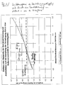
- the distance of the belt stabilization device, hereinafter also abbreviated to belt stabilization, of the wiping nozzles should not exceed their bandwidth for wider belts (B> 1400 mm). For narrower bands (B ⁇ 1400 mm), a margin of up to 1.75 times the bandwidth can be allowed. This distance results from the principle of Staint-Venant, which states that with increasing distance of an attacking force on z. B. a clamped steel strip whose effect on the overall state decreases.
- the basis for the solution according to the invention is the positioning of the strip stabilizer to the wiping nozzle or the wiping nozzles, taking into account the stress mechanism.
- the above object is further achieved by the claimed hot dip coating equipment.
- This is characterized in that the distance (effect) of the strip stabilization from the wiping nozzles is set to a value less than or equal to a distance threshold determined as a function of the bandwidth taking into account a factor Phi as a function of strip thickness and strip tension.
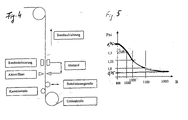
- the arrangement of the belt stabilization and the wiper nozzle is in principle from the FIG. 4 seen.
- the distance threshold results according to the principle of Venant for continuous wide steel bands to about the bandwidth and for narrower bands to max. 1.75 times the bandwidth (see FIG. 5 ). At a greater distance is the effect of the band stabilization with respect to a smoothing of the band profile (transverse arc, S-shape, see Fig. 2 ) very limited or no longer recognizable at long distances.
- the following device for combining the strip stabilization with the wiping nozzle, in which the strip stabilizing coils always act towards the centered strip layer:
- the stabilization must be respectively aligned to the band position and the actual position must be determined.
- the alignment is done by means of specially mounted alignment aids.
- the stabilization is mounted on this frame and is thus mechanically fixed and reproducibly adjustable ( Fig. 3 ).
- the centering on the band position or band center is therefore always identical between stabilization and the scraper nozzle.
- Wiping nozzles and stabilizing coils are mechanically synchronized and aligned!
Priority Applications (1)
| Application Number | Priority Date | Filing Date | Title |
|---|---|---|---|
| PL08801674T PL2188403T3 (pl) | 2007-08-22 | 2008-08-22 | Sposób i instalacja do uszlachetniania zanurzeniowego do stabilizowania prowadzonej pomiędzy dyszami zgarniającymi instalacji do uszlachetniania zanurzeniowego, pokrytej powłoką taśmy |
Applications Claiming Priority (2)
| Application Number | Priority Date | Filing Date | Title |
|---|---|---|---|
| DE102007039690 | 2007-08-22 | ||
| PCT/EP2008/006923 WO2009024353A2 (de) | 2007-08-22 | 2008-08-22 | Verfahren und schmelztauchveredelungsanlage zur bandstabilisierung eines zwischen abstreifdüsen der schmelztauchveredelungsanlage geführten, mit einer beschichtung versehenen bandes |
Publications (2)
| Publication Number | Publication Date |
|---|---|
| EP2188403A2 EP2188403A2 (de) | 2010-05-26 |
| EP2188403B1 true EP2188403B1 (de) | 2012-07-25 |
Family
ID=39967543
Family Applications (1)
| Application Number | Title | Priority Date | Filing Date |
|---|---|---|---|
| EP08801674A Active EP2188403B1 (de) | 2007-08-22 | 2008-08-22 | Verfahren und schmelztauchveredelungsanlage zur bandstabilisierung eines zwischen abstreifdüsen der schmelztauchveredelungsanlage geführten, mit einer beschichtung versehenen bandes |
Country Status (15)
| Country | Link |
|---|---|
| US (1) | US20100285239A1 (zh) |
| EP (1) | EP2188403B1 (zh) |
| JP (1) | JP5355568B2 (zh) |
| KR (1) | KR101185395B1 (zh) |
| CN (1) | CN101784689B (zh) |
| AU (1) | AU2008290746B2 (zh) |
| BR (1) | BRPI0815633B1 (zh) |
| CA (1) | CA2697194C (zh) |
| DE (1) | DE102008039244A1 (zh) |
| ES (1) | ES2387835T3 (zh) |
| MX (1) | MX2010002049A (zh) |
| MY (1) | MY164257A (zh) |
| PL (1) | PL2188403T3 (zh) |
| RU (1) | RU2436861C1 (zh) |
| WO (1) | WO2009024353A2 (zh) |
Cited By (1)
| Publication number | Priority date | Publication date | Assignee | Title |
|---|---|---|---|---|
| US10982307B2 (en) | 2016-02-23 | 2021-04-20 | Fontaine Engineering Und Maschinen Gmbh | Method for operating a coating device for coating a metal strip, and coating device |
Families Citing this family (10)
| Publication number | Priority date | Publication date | Assignee | Title |
|---|---|---|---|---|
| FR2905955B1 (fr) * | 2006-09-18 | 2009-02-13 | Vai Clecim Soc Par Actions Sim | Dispositif de guidage d'une bande dans un bain liquide |
| DE102009051932A1 (de) * | 2009-11-04 | 2011-05-05 | Sms Siemag Ag | Vorrichtung zum Beschichten eines metallischen Bandes und Verfahren hierfür |
| KR101322066B1 (ko) | 2010-12-10 | 2013-10-28 | 주식회사 포스코 | 강판 제진장치 |
| DE102012000662A1 (de) | 2012-01-14 | 2013-07-18 | Fontaine Engineering Und Maschinen Gmbh | Vorrichtung zum Beschichten eines metallischen Bandes mit einem Beschichtungsmaterial |
| JP6065921B2 (ja) * | 2013-07-22 | 2017-01-25 | Jfeスチール株式会社 | 鋼板の製造方法 |
| NO2786187T3 (zh) * | 2014-11-21 | 2018-07-28 | ||
| DE102015216721B3 (de) | 2015-09-01 | 2016-11-24 | Fontaine Engineering Und Maschinen Gmbh | Vorrichtung zum Behandeln eines Metallbandes |
| DE102016222230A1 (de) * | 2016-08-26 | 2018-03-01 | Sms Group Gmbh | Verfahren und Beschichtungseinrichtung zum Beschichten eines Metallbandes |
| WO2018155245A1 (ja) * | 2017-02-24 | 2018-08-30 | Jfeスチール株式会社 | 連続溶融金属めっき処理装置及び該装置を用いた溶融金属めっき処理方法 |
| DE102017109559B3 (de) | 2017-05-04 | 2018-07-26 | Fontaine Engineering Und Maschinen Gmbh | Vorrichtung zum Behandeln eines Metallbandes |
Family Cites Families (18)
| Publication number | Priority date | Publication date | Assignee | Title |
|---|---|---|---|---|
| GB1351125A (en) * | 1970-04-15 | 1974-04-24 | British Steel Corp | Method of and apparatus for controlling a moving metal sheet to conform to a predetermined plane |
| US5401317A (en) * | 1992-04-01 | 1995-03-28 | Weirton Steel Corporation | Coating control apparatus |
| JPH10298727A (ja) * | 1997-04-23 | 1998-11-10 | Nkk Corp | 鋼板の振動・形状制御装置 |
| TW476679B (en) * | 1999-05-26 | 2002-02-21 | Shinko Electric Co Ltd | Device for suppressing the vibration of a steel plate |
| SE0002890D0 (sv) | 2000-08-11 | 2000-08-11 | Po Hang Iron & Steel | A method for controlling the thickness of a galvanising coating on a metallic object |
| JP2005097748A (ja) * | 2001-03-15 | 2005-04-14 | Jfe Steel Kk | 溶融めっき金属帯の製造方法及び製造装置 |
| KR100502816B1 (ko) * | 2001-03-15 | 2005-07-20 | 제이에프이 스틸 가부시키가이샤 | 용융도금 금속스트립의 제조방법 및 그 장치 |
| JP3868249B2 (ja) * | 2001-07-30 | 2007-01-17 | 三菱重工業株式会社 | 鋼板形状矯正装置 |
| JP3530514B2 (ja) * | 2001-08-02 | 2004-05-24 | 三菱重工業株式会社 | 鋼板形状矯正装置及び方法 |
| JP3901969B2 (ja) * | 2001-08-29 | 2007-04-04 | 三菱重工業株式会社 | 鋼板の制振装置 |
| JP2003105515A (ja) * | 2001-09-26 | 2003-04-09 | Mitsubishi Heavy Ind Ltd | 鋼板形状矯正装置及び方法 |
| EP1538233A1 (en) * | 2002-09-13 | 2005-06-08 | JFE Steel Corporation | Method and apparatus for producing hot-dip coated metal belt |
| SE527507C2 (sv) * | 2004-07-13 | 2006-03-28 | Abb Ab | En anordning och ett förfarande för stabilisering av ett metalliskt föremål samt en användning av anordningen |
| JP5123165B2 (ja) * | 2005-03-24 | 2013-01-16 | アーベーベー・リサーチ・リミテッド | 鋼板を安定させるためのデバイス及び方法 |
| SE529060C2 (sv) * | 2005-06-30 | 2007-04-24 | Abb Ab | Anordning samt förfarande för tjockleksstyrning |
| DE102005030766A1 (de) * | 2005-07-01 | 2007-01-04 | Sms Demag Ag | Vorrichtung zur Schmelztauchbeschichtung eines Metallstranges |
| DE102005060058B4 (de) * | 2005-12-15 | 2016-01-28 | Emg Automation Gmbh | Verfahren und Vorrichtung zum Stabilisieren eines Bandes |
| SE531120C2 (sv) * | 2007-09-25 | 2008-12-23 | Abb Research Ltd | En anordning och ett förfarande för stabilisering och visuell övervakning av ett långsträckt metalliskt band |
-
2008
- 2008-08-22 DE DE102008039244A patent/DE102008039244A1/de not_active Withdrawn
- 2008-08-22 ES ES08801674T patent/ES2387835T3/es active Active
- 2008-08-22 JP JP2010520505A patent/JP5355568B2/ja active Active
- 2008-08-22 RU RU2010110581/02A patent/RU2436861C1/ru active
- 2008-08-22 WO PCT/EP2008/006923 patent/WO2009024353A2/de active Application Filing
- 2008-08-22 AU AU2008290746A patent/AU2008290746B2/en active Active
- 2008-08-22 KR KR1020107002284A patent/KR101185395B1/ko active IP Right Grant
- 2008-08-22 MY MYPI2010000641A patent/MY164257A/en unknown
- 2008-08-22 CN CN2008801038920A patent/CN101784689B/zh active Active
- 2008-08-22 US US12/733,274 patent/US20100285239A1/en not_active Abandoned
- 2008-08-22 EP EP08801674A patent/EP2188403B1/de active Active
- 2008-08-22 CA CA2697194A patent/CA2697194C/en active Active
- 2008-08-22 BR BRPI0815633A patent/BRPI0815633B1/pt active IP Right Grant
- 2008-08-22 MX MX2010002049A patent/MX2010002049A/es active IP Right Grant
- 2008-08-22 PL PL08801674T patent/PL2188403T3/pl unknown
Cited By (1)
| Publication number | Priority date | Publication date | Assignee | Title |
|---|---|---|---|---|
| US10982307B2 (en) | 2016-02-23 | 2021-04-20 | Fontaine Engineering Und Maschinen Gmbh | Method for operating a coating device for coating a metal strip, and coating device |
Also Published As
| Publication number | Publication date |
|---|---|
| JP2010535945A (ja) | 2010-11-25 |
| BRPI0815633B1 (pt) | 2018-10-23 |
| KR101185395B1 (ko) | 2012-09-25 |
| BRPI0815633A2 (pt) | 2015-02-18 |
| ES2387835T3 (es) | 2012-10-02 |
| WO2009024353A2 (de) | 2009-02-26 |
| JP5355568B2 (ja) | 2013-11-27 |
| RU2436861C1 (ru) | 2011-12-20 |
| AU2008290746A1 (en) | 2009-02-26 |
| PL2188403T3 (pl) | 2012-12-31 |
| MY164257A (en) | 2017-11-30 |
| CN101784689A (zh) | 2010-07-21 |
| CA2697194A1 (en) | 2009-02-26 |
| RU2010110581A (ru) | 2011-09-27 |
| CN101784689B (zh) | 2013-06-26 |
| MX2010002049A (es) | 2010-05-03 |
| EP2188403A2 (de) | 2010-05-26 |
| DE102008039244A1 (de) | 2009-03-12 |
| CA2697194C (en) | 2012-03-06 |
| KR20100030664A (ko) | 2010-03-18 |
| WO2009024353A3 (de) | 2010-01-21 |
| US20100285239A1 (en) | 2010-11-11 |
| AU2008290746B2 (en) | 2011-09-08 |
Similar Documents
| Publication | Publication Date | Title |
|---|---|---|
| EP2188403B1 (de) | Verfahren und schmelztauchveredelungsanlage zur bandstabilisierung eines zwischen abstreifdüsen der schmelztauchveredelungsanlage geführten, mit einer beschichtung versehenen bandes | |
| EP1794339B1 (de) | Verfahren zur bandbeschichtung | |
| EP1944570B1 (de) | Verfahren zur Messung der Geradheit von Langprodukten | |
| EP3221487B1 (de) | Verfahren und vorrichtung zum beschichten eines metallbandes | |
| DE19719994B4 (de) | Verfahren zur Beeinflussung der Spannungsverteilung in Metallbändern oder -tafeln aus insbesondere nichtferromagnetischem Material | |
| JP2010535945A5 (zh) | ||
| EP3504352A1 (de) | Verfahren und beschichtungseinrichtung zum beschichten eines metallbandes | |
| EP3051013A1 (de) | Verfahren zur Führung einer Vliesbahn und Vliesbahn-Führungsvorrichtung | |
| DE102008049537A1 (de) | Verfahren und Vorrichtung zum Kühlen eines Vorbandes oder Bandes eines Metallstrangs in einem Warmwalzwerk | |
| EP2190602A1 (de) | Vorrichtung und verfahren zur bandlageregelung | |
| EP3443153A1 (de) | Vorrichtung an einer karde oder krempel | |
| AT500766A1 (de) | Verfahren und vorrichtung zur vermeidung von schwingungen | |
| WO2013167366A1 (de) | Verfahren zur bearbeitung von walzgut und walzwerk | |
| DE102007045202A1 (de) | Vorrichtung zur Bandkantenstabilisierung | |
| DE19725726C2 (de) | Verfahren zur Planheitsmessung von Bändern, insbesondere Metallbändern | |
| DE3048672C2 (zh) | ||
| EP3441157A1 (de) | Verfahren und anlage zum stranggiessen eines metallischen produkts | |
| DE102007010578A1 (de) | Vorrichtung zum Gießen von Strängen aus Metall | |
| DE102016222224A1 (de) | Verfahren zum Betreiben einer Beschichtungseinrichtung zum Beschichten eines Metallbandes sowie Beschichtungseinrichtung | |
| AT518461A1 (de) | Gießspiegelregelung mit Störgrößenkompensation | |
| AT410409B (de) | Verfahren zum stranggiessen von metallschmelzen sowie stranggiessanlage zur durchführung des verfahrens | |
| EP3795267B1 (de) | Verfahren zum betreiben eines walzgerüstes | |
| EP1230993B1 (de) | Vorrichtung zur Verbesserung der Planheit von gewalztem Band, insbesondere von Stahlband | |
| WO2018041794A1 (de) | Rührspulenanordnung in einer stranggiessanlage | |
| EP2666558A1 (de) | Seitenführung für eine Walzstraße |
Legal Events
| Date | Code | Title | Description |
|---|---|---|---|
| PUAI | Public reference made under article 153(3) epc to a published international application that has entered the european phase |
Free format text: ORIGINAL CODE: 0009012 |
|
| AK | Designated contracting states |
Kind code of ref document: A2 Designated state(s): AT BE BG CH CY CZ DE DK EE ES FI FR GB GR HR HU IE IS IT LI LT LU LV MC MT NL NO PL PT RO SE SI SK TR |
|
| AX | Request for extension of the european patent |
Extension state: AL BA MK RS |
|
| RBV | Designated contracting states (corrected) |
Designated state(s): AT BE BG CH CY CZ DE DK EE ES FI FR GB GR HR HU IE IS IT LI LT LU LV MC MT NL NO PL PT RO SE SI SK TR |
|
| 17P | Request for examination filed |
Effective date: 20100121 |
|
| DAX | Request for extension of the european patent (deleted) | ||
| GRAP | Despatch of communication of intention to grant a patent |
Free format text: ORIGINAL CODE: EPIDOSNIGR1 |
|
| GRAS | Grant fee paid |
Free format text: ORIGINAL CODE: EPIDOSNIGR3 |
|
| GRAA | (expected) grant |
Free format text: ORIGINAL CODE: 0009210 |
|
| AK | Designated contracting states |
Kind code of ref document: B1 Designated state(s): AT BE BG CH CY CZ DE DK EE ES FI FR GB GR HR HU IE IS IT LI LT LU LV MC MT NL NO PL PT RO SE SI SK TR |
|
| REG | Reference to a national code |
Ref country code: GB Ref legal event code: FG4D Free format text: NOT ENGLISH |
|
| REG | Reference to a national code |
Ref country code: CH Ref legal event code: EP |
|
| REG | Reference to a national code |
Ref country code: AT Ref legal event code: REF Ref document number: 567757 Country of ref document: AT Kind code of ref document: T Effective date: 20120815 Ref country code: IE Ref legal event code: FG4D Free format text: LANGUAGE OF EP DOCUMENT: GERMAN |
|
| REG | Reference to a national code |
Ref country code: DE Ref legal event code: R096 Ref document number: 502008007780 Country of ref document: DE Effective date: 20120920 |
|
| REG | Reference to a national code |
Ref country code: SE Ref legal event code: TRGR Ref country code: ES Ref legal event code: FG2A Ref document number: 2387835 Country of ref document: ES Kind code of ref document: T3 Effective date: 20121002 |
|
| REG | Reference to a national code |
Ref country code: NL Ref legal event code: T3 |
|
| REG | Reference to a national code |
Ref country code: SK Ref legal event code: T3 Ref document number: E 12490 Country of ref document: SK |
|
| REG | Reference to a national code |
Ref country code: LT Ref legal event code: MG4D Effective date: 20120725 |
|
| REG | Reference to a national code |
Ref country code: PL Ref legal event code: T3 |
|
| PG25 | Lapsed in a contracting state [announced via postgrant information from national office to epo] |
Ref country code: NO Free format text: LAPSE BECAUSE OF FAILURE TO SUBMIT A TRANSLATION OF THE DESCRIPTION OR TO PAY THE FEE WITHIN THE PRESCRIBED TIME-LIMIT Effective date: 20121025 Ref country code: IS Free format text: LAPSE BECAUSE OF FAILURE TO SUBMIT A TRANSLATION OF THE DESCRIPTION OR TO PAY THE FEE WITHIN THE PRESCRIBED TIME-LIMIT Effective date: 20121125 Ref country code: LT Free format text: LAPSE BECAUSE OF FAILURE TO SUBMIT A TRANSLATION OF THE DESCRIPTION OR TO PAY THE FEE WITHIN THE PRESCRIBED TIME-LIMIT Effective date: 20120725 Ref country code: CY Free format text: LAPSE BECAUSE OF FAILURE TO SUBMIT A TRANSLATION OF THE DESCRIPTION OR TO PAY THE FEE WITHIN THE PRESCRIBED TIME-LIMIT Effective date: 20120725 Ref country code: HR Free format text: LAPSE BECAUSE OF FAILURE TO SUBMIT A TRANSLATION OF THE DESCRIPTION OR TO PAY THE FEE WITHIN THE PRESCRIBED TIME-LIMIT Effective date: 20120725 |
|
| PG25 | Lapsed in a contracting state [announced via postgrant information from national office to epo] |
Ref country code: SI Free format text: LAPSE BECAUSE OF FAILURE TO SUBMIT A TRANSLATION OF THE DESCRIPTION OR TO PAY THE FEE WITHIN THE PRESCRIBED TIME-LIMIT Effective date: 20120725 Ref country code: GR Free format text: LAPSE BECAUSE OF FAILURE TO SUBMIT A TRANSLATION OF THE DESCRIPTION OR TO PAY THE FEE WITHIN THE PRESCRIBED TIME-LIMIT Effective date: 20121026 Ref country code: LV Free format text: LAPSE BECAUSE OF FAILURE TO SUBMIT A TRANSLATION OF THE DESCRIPTION OR TO PAY THE FEE WITHIN THE PRESCRIBED TIME-LIMIT Effective date: 20120725 Ref country code: PT Free format text: LAPSE BECAUSE OF FAILURE TO SUBMIT A TRANSLATION OF THE DESCRIPTION OR TO PAY THE FEE WITHIN THE PRESCRIBED TIME-LIMIT Effective date: 20121126 |
|
| REG | Reference to a national code |
Ref country code: CH Ref legal event code: PL |
|
| PG25 | Lapsed in a contracting state [announced via postgrant information from national office to epo] |
Ref country code: MC Free format text: LAPSE BECAUSE OF NON-PAYMENT OF DUE FEES Effective date: 20120831 |
|
| PG25 | Lapsed in a contracting state [announced via postgrant information from national office to epo] |
Ref country code: CH Free format text: LAPSE BECAUSE OF NON-PAYMENT OF DUE FEES Effective date: 20120831 Ref country code: DK Free format text: LAPSE BECAUSE OF FAILURE TO SUBMIT A TRANSLATION OF THE DESCRIPTION OR TO PAY THE FEE WITHIN THE PRESCRIBED TIME-LIMIT Effective date: 20120725 Ref country code: EE Free format text: LAPSE BECAUSE OF FAILURE TO SUBMIT A TRANSLATION OF THE DESCRIPTION OR TO PAY THE FEE WITHIN THE PRESCRIBED TIME-LIMIT Effective date: 20120725 Ref country code: RO Free format text: LAPSE BECAUSE OF FAILURE TO SUBMIT A TRANSLATION OF THE DESCRIPTION OR TO PAY THE FEE WITHIN THE PRESCRIBED TIME-LIMIT Effective date: 20120725 Ref country code: LI Free format text: LAPSE BECAUSE OF NON-PAYMENT OF DUE FEES Effective date: 20120831 Ref country code: CZ Free format text: LAPSE BECAUSE OF FAILURE TO SUBMIT A TRANSLATION OF THE DESCRIPTION OR TO PAY THE FEE WITHIN THE PRESCRIBED TIME-LIMIT Effective date: 20120725 |
|
| REG | Reference to a national code |
Ref country code: IE Ref legal event code: MM4A |
|
| PLBE | No opposition filed within time limit |
Free format text: ORIGINAL CODE: 0009261 |
|
| STAA | Information on the status of an ep patent application or granted ep patent |
Free format text: STATUS: NO OPPOSITION FILED WITHIN TIME LIMIT |
|
| 26N | No opposition filed |
Effective date: 20130426 |
|
| PG25 | Lapsed in a contracting state [announced via postgrant information from national office to epo] |
Ref country code: IE Free format text: LAPSE BECAUSE OF NON-PAYMENT OF DUE FEES Effective date: 20120822 Ref country code: BG Free format text: LAPSE BECAUSE OF FAILURE TO SUBMIT A TRANSLATION OF THE DESCRIPTION OR TO PAY THE FEE WITHIN THE PRESCRIBED TIME-LIMIT Effective date: 20121025 |
|
| REG | Reference to a national code |
Ref country code: DE Ref legal event code: R097 Ref document number: 502008007780 Country of ref document: DE Effective date: 20130426 |
|
| PG25 | Lapsed in a contracting state [announced via postgrant information from national office to epo] |
Ref country code: MT Free format text: LAPSE BECAUSE OF FAILURE TO SUBMIT A TRANSLATION OF THE DESCRIPTION OR TO PAY THE FEE WITHIN THE PRESCRIBED TIME-LIMIT Effective date: 20120725 |
|
| PG25 | Lapsed in a contracting state [announced via postgrant information from national office to epo] |
Ref country code: HU Free format text: LAPSE BECAUSE OF FAILURE TO SUBMIT A TRANSLATION OF THE DESCRIPTION OR TO PAY THE FEE WITHIN THE PRESCRIBED TIME-LIMIT Effective date: 20080822 |
|
| REG | Reference to a national code |
Ref country code: DE Ref legal event code: R082 Ref document number: 502008007780 Country of ref document: DE Representative=s name: HEMMERICH & KOLLEGEN, DE Ref country code: DE Ref legal event code: R081 Ref document number: 502008007780 Country of ref document: DE Owner name: SMS GROUP GMBH, DE Free format text: FORMER OWNER: SMS SIEMAG AG, 40237 DUESSELDORF, DE |
|
| REG | Reference to a national code |
Ref country code: SK Ref legal event code: TC4A Ref document number: E 12490 Country of ref document: SK Owner name: SMS GROUP GMBH, DUESSELDORF, DE Effective date: 20160209 |
|
| REG | Reference to a national code |
Ref country code: FR Ref legal event code: PLFP Year of fee payment: 9 |
|
| REG | Reference to a national code |
Ref country code: FR Ref legal event code: PLFP Year of fee payment: 10 |
|
| REG | Reference to a national code |
Ref country code: FR Ref legal event code: PLFP Year of fee payment: 11 |
|
| P01 | Opt-out of the competence of the unified patent court (upc) registered |
Effective date: 20230517 |
|
| PGFP | Annual fee paid to national office [announced via postgrant information from national office to epo] |
Ref country code: NL Payment date: 20230821 Year of fee payment: 16 Ref country code: LU Payment date: 20230821 Year of fee payment: 16 |
|
| PGFP | Annual fee paid to national office [announced via postgrant information from national office to epo] |
Ref country code: TR Payment date: 20230821 Year of fee payment: 16 Ref country code: IT Payment date: 20230825 Year of fee payment: 16 Ref country code: GB Payment date: 20230822 Year of fee payment: 16 Ref country code: FI Payment date: 20230821 Year of fee payment: 16 Ref country code: AT Payment date: 20230822 Year of fee payment: 16 |
|
| PGFP | Annual fee paid to national office [announced via postgrant information from national office to epo] |
Ref country code: SK Payment date: 20230814 Year of fee payment: 16 Ref country code: SE Payment date: 20230821 Year of fee payment: 16 Ref country code: PL Payment date: 20230811 Year of fee payment: 16 Ref country code: FR Payment date: 20230824 Year of fee payment: 16 Ref country code: DE Payment date: 20230821 Year of fee payment: 16 Ref country code: BE Payment date: 20230821 Year of fee payment: 16 |
|
| PGFP | Annual fee paid to national office [announced via postgrant information from national office to epo] |
Ref country code: ES Payment date: 20231027 Year of fee payment: 16 |