EP2188403B1 - Process and hot-dip coating system for stabilizing a strip guided between stripping dies of the hot-dip coating system and provided with a coating - Google Patents
Process and hot-dip coating system for stabilizing a strip guided between stripping dies of the hot-dip coating system and provided with a coating Download PDFInfo
- Publication number
- EP2188403B1 EP2188403B1 EP08801674A EP08801674A EP2188403B1 EP 2188403 B1 EP2188403 B1 EP 2188403B1 EP 08801674 A EP08801674 A EP 08801674A EP 08801674 A EP08801674 A EP 08801674A EP 2188403 B1 EP2188403 B1 EP 2188403B1
- Authority
- EP
- European Patent Office
- Prior art keywords
- strip
- hot
- distance
- detected
- width
- Prior art date
- Legal status (The legal status is an assumption and is not a legal conclusion. Google has not performed a legal analysis and makes no representation as to the accuracy of the status listed.)
- Active
Links
- 238000000034 method Methods 0.000 title claims abstract description 16
- 239000011248 coating agent Substances 0.000 title claims abstract description 15
- 238000000576 coating method Methods 0.000 title claims abstract description 15
- 230000000087 stabilizing effect Effects 0.000 title abstract description 13
- 238000003618 dip coating Methods 0.000 title abstract description 9
- 230000008569 process Effects 0.000 title abstract description 3
- 230000006641 stabilisation Effects 0.000 claims abstract description 47
- 229910000831 Steel Inorganic materials 0.000 claims abstract description 13
- 239000010959 steel Substances 0.000 claims abstract description 13
- 230000010355 oscillation Effects 0.000 claims description 6
- 238000009826 distribution Methods 0.000 claims description 5
- 230000008859 change Effects 0.000 claims description 4
- 238000005259 measurement Methods 0.000 claims description 4
- 230000003019 stabilising effect Effects 0.000 claims 5
- 238000011105 stabilization Methods 0.000 abstract description 42
- 230000000694 effects Effects 0.000 description 19
- 238000009499 grossing Methods 0.000 description 6
- 230000008901 benefit Effects 0.000 description 3
- 238000013016 damping Methods 0.000 description 3
- 230000007423 decrease Effects 0.000 description 3
- 230000009467 reduction Effects 0.000 description 3
- 238000004088 simulation Methods 0.000 description 3
- 239000003381 stabilizer Substances 0.000 description 3
- IJGRMHOSHXDMSA-UHFFFAOYSA-N Atomic nitrogen Chemical compound N#N IJGRMHOSHXDMSA-UHFFFAOYSA-N 0.000 description 2
- 230000033228 biological regulation Effects 0.000 description 2
- 230000008878 coupling Effects 0.000 description 2
- 238000010168 coupling process Methods 0.000 description 2
- 238000005859 coupling reaction Methods 0.000 description 2
- 230000010354 integration Effects 0.000 description 2
- HCHKCACWOHOZIP-UHFFFAOYSA-N Zinc Chemical compound [Zn] HCHKCACWOHOZIP-UHFFFAOYSA-N 0.000 description 1
- 230000002411 adverse Effects 0.000 description 1
- 230000000712 assembly Effects 0.000 description 1
- 238000000429 assembly Methods 0.000 description 1
- 230000002238 attenuated effect Effects 0.000 description 1
- 238000004364 calculation method Methods 0.000 description 1
- 238000010276 construction Methods 0.000 description 1
- 238000001816 cooling Methods 0.000 description 1
- 238000012937 correction Methods 0.000 description 1
- 230000001419 dependent effect Effects 0.000 description 1
- 238000013461 design Methods 0.000 description 1
- 230000005489 elastic deformation Effects 0.000 description 1
- 230000005294 ferromagnetic effect Effects 0.000 description 1
- 230000006872 improvement Effects 0.000 description 1
- 230000006698 induction Effects 0.000 description 1
- 238000009434 installation Methods 0.000 description 1
- 230000001788 irregular Effects 0.000 description 1
- 229910001338 liquidmetal Inorganic materials 0.000 description 1
- 230000005291 magnetic effect Effects 0.000 description 1
- 238000004519 manufacturing process Methods 0.000 description 1
- 230000007246 mechanism Effects 0.000 description 1
- 229910052757 nitrogen Inorganic materials 0.000 description 1
- 238000012545 processing Methods 0.000 description 1
- 238000007790 scraping Methods 0.000 description 1
- 230000001360 synchronised effect Effects 0.000 description 1
- 230000002123 temporal effect Effects 0.000 description 1
- 238000012360 testing method Methods 0.000 description 1
- 229910052725 zinc Inorganic materials 0.000 description 1
- 239000011701 zinc Substances 0.000 description 1
Images

Classifications
-
- C—CHEMISTRY; METALLURGY
- C23—COATING METALLIC MATERIAL; COATING MATERIAL WITH METALLIC MATERIAL; CHEMICAL SURFACE TREATMENT; DIFFUSION TREATMENT OF METALLIC MATERIAL; COATING BY VACUUM EVAPORATION, BY SPUTTERING, BY ION IMPLANTATION OR BY CHEMICAL VAPOUR DEPOSITION, IN GENERAL; INHIBITING CORROSION OF METALLIC MATERIAL OR INCRUSTATION IN GENERAL
- C23C—COATING METALLIC MATERIAL; COATING MATERIAL WITH METALLIC MATERIAL; SURFACE TREATMENT OF METALLIC MATERIAL BY DIFFUSION INTO THE SURFACE, BY CHEMICAL CONVERSION OR SUBSTITUTION; COATING BY VACUUM EVAPORATION, BY SPUTTERING, BY ION IMPLANTATION OR BY CHEMICAL VAPOUR DEPOSITION, IN GENERAL
- C23C2/00—Hot-dipping or immersion processes for applying the coating material in the molten state without affecting the shape; Apparatus therefor
- C23C2/003—Apparatus
-
- C—CHEMISTRY; METALLURGY
- C23—COATING METALLIC MATERIAL; COATING MATERIAL WITH METALLIC MATERIAL; CHEMICAL SURFACE TREATMENT; DIFFUSION TREATMENT OF METALLIC MATERIAL; COATING BY VACUUM EVAPORATION, BY SPUTTERING, BY ION IMPLANTATION OR BY CHEMICAL VAPOUR DEPOSITION, IN GENERAL; INHIBITING CORROSION OF METALLIC MATERIAL OR INCRUSTATION IN GENERAL
- C23C—COATING METALLIC MATERIAL; COATING MATERIAL WITH METALLIC MATERIAL; SURFACE TREATMENT OF METALLIC MATERIAL BY DIFFUSION INTO THE SURFACE, BY CHEMICAL CONVERSION OR SUBSTITUTION; COATING BY VACUUM EVAPORATION, BY SPUTTERING, BY ION IMPLANTATION OR BY CHEMICAL VAPOUR DEPOSITION, IN GENERAL
- C23C2/00—Hot-dipping or immersion processes for applying the coating material in the molten state without affecting the shape; Apparatus therefor
- C23C2/14—Removing excess of molten coatings; Controlling or regulating the coating thickness
- C23C2/24—Removing excess of molten coatings; Controlling or regulating the coating thickness using magnetic or electric fields
-
- C—CHEMISTRY; METALLURGY
- C23—COATING METALLIC MATERIAL; COATING MATERIAL WITH METALLIC MATERIAL; CHEMICAL SURFACE TREATMENT; DIFFUSION TREATMENT OF METALLIC MATERIAL; COATING BY VACUUM EVAPORATION, BY SPUTTERING, BY ION IMPLANTATION OR BY CHEMICAL VAPOUR DEPOSITION, IN GENERAL; INHIBITING CORROSION OF METALLIC MATERIAL OR INCRUSTATION IN GENERAL
- C23C—COATING METALLIC MATERIAL; COATING MATERIAL WITH METALLIC MATERIAL; SURFACE TREATMENT OF METALLIC MATERIAL BY DIFFUSION INTO THE SURFACE, BY CHEMICAL CONVERSION OR SUBSTITUTION; COATING BY VACUUM EVAPORATION, BY SPUTTERING, BY ION IMPLANTATION OR BY CHEMICAL VAPOUR DEPOSITION, IN GENERAL
- C23C2/00—Hot-dipping or immersion processes for applying the coating material in the molten state without affecting the shape; Apparatus therefor
- C23C2/34—Hot-dipping or immersion processes for applying the coating material in the molten state without affecting the shape; Apparatus therefor characterised by the shape of the material to be treated
- C23C2/36—Elongated material
- C23C2/40—Plates; Strips
-
- C—CHEMISTRY; METALLURGY
- C23—COATING METALLIC MATERIAL; COATING MATERIAL WITH METALLIC MATERIAL; CHEMICAL SURFACE TREATMENT; DIFFUSION TREATMENT OF METALLIC MATERIAL; COATING BY VACUUM EVAPORATION, BY SPUTTERING, BY ION IMPLANTATION OR BY CHEMICAL VAPOUR DEPOSITION, IN GENERAL; INHIBITING CORROSION OF METALLIC MATERIAL OR INCRUSTATION IN GENERAL
- C23C—COATING METALLIC MATERIAL; COATING MATERIAL WITH METALLIC MATERIAL; SURFACE TREATMENT OF METALLIC MATERIAL BY DIFFUSION INTO THE SURFACE, BY CHEMICAL CONVERSION OR SUBSTITUTION; COATING BY VACUUM EVAPORATION, BY SPUTTERING, BY ION IMPLANTATION OR BY CHEMICAL VAPOUR DEPOSITION, IN GENERAL
- C23C2/00—Hot-dipping or immersion processes for applying the coating material in the molten state without affecting the shape; Apparatus therefor
- C23C2/50—Controlling or regulating the coating processes
- C23C2/52—Controlling or regulating the coating processes with means for measuring or sensing
Definitions
- the invention relates to a method for stabilizing the strip of a tape provided with a coating between stripping nozzles of a hot-dip coating plant and a corresponding hot-dip coating installation.
- a method for stabilizing the strip of a tape provided with a coating between stripping nozzles of a hot-dip coating plant and a corresponding hot-dip coating installation.
- Electromagnetic band stabilizers are based on the principle of induction, in order to generate attractive forces perpendicular to the ferromagnetic steel strip by means of defined magnetic fields. Thus, the position of the steel strip between two opposite electromagnetic inductors (electromagnets) can be changed without contact.
- Such systems are known in different types. They are used, for example, in hot-dip coating plants in the coating area above the so-called wiping nozzles. Different regulation. and control concepts are known (e.g. DE 10 2005 060 058 A1 . WO 2006/006911 A1 . WO 02/14572 A1 ).
- Wiping nozzles are used in hot-dip coating plants for steel strip to obtain a defined amount of coating medium on the strip surface.
- the quality of the coating depends to a large extent on the uniformity of the wiping medium (eg air or nitrogen) as well as on the band movement in the nozzle area.
- the belt movements are caused by non-circularity of roles or eg by pulse effect of the air in the cooling tower area of hot dip finishing plants.
- belt stabilization systems connected downstream in the belt running direction can damp or reduce a belt movement occurring within the scraping nozzle, so that an improvement in the coating accuracy and coating uniformity of the liquid metal on the steel belt is achieved.
- This can z. B. electromagnetically acting actuators exercise the non-contact attractive forces on the continuous steel band and thus change the band position.
- the goal of all applications is to position the belt stabilization as close as possible to the wiper nozzle, ignoring the relationship between distance and effect.
- the object of the invention is therefore to improve the strip stabilization in the region of the wiper.
- This object is achieved according to the invention with the method according to claim 1.
- This is characterized in that the distance (the effect) of the band stabilization of the wiping nozzles is set to a value equal to a distance threshold value, which as a function of Bandwidth is determined taking into account a factor Phi, wherein the factor Phi is calculated as a function of the strip thickness and the strip tension.
- the measured quantity strip position represents the temporal and / or local change of the distance of the strip with respect to a straight reference line transversely to the strip running direction; that is, the tape position represents the tape profile and / or its vibration behavior as a function of time.
- strip stabilization encompasses two essential aspects in the context of the present description: On the one hand, strip stabilization means smoothing of a wave-shaped strip profile, and on the other hand, this term means damping of vibrations of the strip. Both aspects of band stabilization can be implemented independently or in combination or simultaneously with the aid of suitable control circuits.
- the essential advantage of the claimed limitation of the distance can be seen in the fact that when the distance is set to a value below the distance threshold value that can be calculated according to the invention, a significantly better effect is achieved for both aspects of the desired band stabilization. In contrast, the effect of band stabilization at intervals above the distance threshold decreases significantly or the band is despite stabilization even more unstable than without control (opposite effect).
- Ideal would be a distance of zero, that is, if the band stabilization at the level of the scrapers would be arranged, because then the band stabilization would act directly at the level of the stripping and the tape would then held optimally stable during a measurement process.
- this arrangement is structurally not feasible due to lack of space in the rule. Therefore, the distance should be as small as possible, but maximally set to the value of the distance threshold value which can be calculated according to the invention.
- the electromagnetic forces are applied by on each band side in pairs opposing coil assemblies whose distance from the wiping nozzles is changeable.
- the band position within the coil arrangement is preferably measured, specifically in the spatial vicinity of the coil arrangement.
- the tape position above and below the coil assembly can be measured.
- a plurality of coils are arranged on each band side, wherein the respective outer coils are arranged to be adjustable on the continuous band edges parallel to the plane of the band.
- the distance of the belt stabilization device, hereinafter also abbreviated to belt stabilization, of the wiping nozzles should not exceed their bandwidth for wider belts (B> 1400 mm). For narrower bands (B ⁇ 1400 mm), a margin of up to 1.75 times the bandwidth can be allowed. This distance results from the principle of Staint-Venant, which states that with increasing distance of an attacking force on z. B. a clamped steel strip whose effect on the overall state decreases.
- the basis for the solution according to the invention is the positioning of the strip stabilizer to the wiping nozzle or the wiping nozzles, taking into account the stress mechanism.
- the above object is further achieved by the claimed hot dip coating equipment.
- This is characterized in that the distance (effect) of the strip stabilization from the wiping nozzles is set to a value less than or equal to a distance threshold determined as a function of the bandwidth taking into account a factor Phi as a function of strip thickness and strip tension.
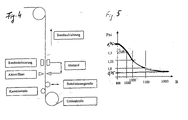
- the arrangement of the belt stabilization and the wiper nozzle is in principle from the FIG. 4 seen.
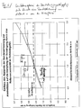
- the distance threshold results according to the principle of Venant for continuous wide steel bands to about the bandwidth and for narrower bands to max. 1.75 times the bandwidth (see FIG. 5 ). At a greater distance is the effect of the band stabilization with respect to a smoothing of the band profile (transverse arc, S-shape, see Fig. 2 ) very limited or no longer recognizable at long distances.
- the following device for combining the strip stabilization with the wiping nozzle, in which the strip stabilizing coils always act towards the centered strip layer:
- the stabilization must be respectively aligned to the band position and the actual position must be determined.
- the alignment is done by means of specially mounted alignment aids.
- the stabilization is mounted on this frame and is thus mechanically fixed and reproducibly adjustable ( Fig. 3 ).
- the centering on the band position or band center is therefore always identical between stabilization and the scraper nozzle.
- Wiping nozzles and stabilizing coils are mechanically synchronized and aligned!
Landscapes
- Chemical & Material Sciences (AREA)
- Chemical Kinetics & Catalysis (AREA)
- Engineering & Computer Science (AREA)
- Materials Engineering (AREA)
- Mechanical Engineering (AREA)
- Metallurgy (AREA)
- Organic Chemistry (AREA)
- Coating With Molten Metal (AREA)
- Coating Apparatus (AREA)
- Controlling Rewinding, Feeding, Winding, Or Abnormalities Of Webs (AREA)
Abstract
Description
Die Erfindung betrifft ein Verfahren zur Bandstabilisierung eines zwischen Abstreifdüsen einer Schmelztauchveredelungsanlage geführten, mit einer Beschichtung versehenen Bandes sowie eine entsprechende Schmelztauchbeschichtungsanlage. Dabei werden durch in Bandlaufrichtung den Abstreifdüsen nachgeordnete elektromagnetisch berührungslos auf das durchlaufende Stahlband wirkende Spulen stabilisierende Kräfte nach Maßgabe der erfassten Bandposition auf das Band ausübt.The invention relates to a method for stabilizing the strip of a tape provided with a coating between stripping nozzles of a hot-dip coating plant and a corresponding hot-dip coating installation. In this case, by acting in the strip running direction downstream of the stripping nozzles electromagnetically contactless acting on the continuous steel strip coils stabilizing forces in accordance with the detected tape position on the tape.
Elektromagnetische Bandstabilisierungen basieren auf dem Prinzip der Induktion, um mittels definierter Magnetfelder anziehende Kräfte senkrecht zum ferromagnetischen Stahlband zu erzeugen. Damit kann die Lage des Stahlbands zwischen zwei gegenüberliegenden elektromagnetischen Induktoren (Elektromagnete) berührungslos verändert werden. Solche Systeme sind in unterschiedlicher Bauart bekannt. Sie werden z.B. in Schmelztauchveredelungsanlagen im Beschichtungsbereich oberhalb der so genannten Abstreifdüsen verwendet. Unterschiedlichste Regelungs. und Steuerungskonzepte sind bekannt (z. B.
Abstreifdüsen werden in Schmelztauchveredelungsanlagen für Stahlband eingesetzt, um eine definierte Menge Beschichtungsmedium auf der Bandoberfläche zu erhalten. Die Qualität der Beschichtung (Gleichmäßigkeit der Auftragung, Schichtdickengenauigkeit, homogener Oberflächenglanz) hängt maßgeblich von der Gleichmäßigkeit des Abstreifdüsenmediums (z.B. Luft oder Stickstoff) sowie von der Bandbewegung im Düsenbereich ab. Die Bandbewegungen werden durch Unrundheiten von Rollen oder z.B. durch Impulswirkung der Luft im Kühlturmbereich von Schmelztauchveredelungsanlagen hervorgerufen.Wiping nozzles are used in hot-dip coating plants for steel strip to obtain a defined amount of coating medium on the strip surface. The quality of the coating (uniformity of application, layer thickness accuracy, homogeneous surface gloss) depends to a large extent on the uniformity of the wiping medium (eg air or nitrogen) as well as on the band movement in the nozzle area. The belt movements are caused by non-circularity of roles or eg by pulse effect of the air in the cooling tower area of hot dip finishing plants.
Mit zunehmender Bandbewegung in der Abstreifdüse reduziert sich die Beschichtungsqualität bzw. Gleichmäßigkeit der Beschichtung des durchlaufenden Stahlbands.As the strip movement in the stripper nozzle increases, the coating quality or uniformity of the coating of the continuous steel strip is reduced.
Durch den Einsatz von in Bandlaufrichtung nach geschalteten Bandstabilisierungssystemen kann eine innerhalb der Abstreifdüse auftretende Bandbewegung gedämpft bzw. reduziert werden, so dass eine Verbesserung der Beschichtungsgenauigkeit und Beschichtungsgleichmäßigkeit des flüssigen Metalls auf dem Stahlband erreicht wird. Dies können z. B. elektromagnetisch wirkende Aktuatoren sein, die berührungslos anziehende Kräfte auf das durchlaufende Stahlband ausüben und somit die Bandlage verändern.The use of belt stabilization systems connected downstream in the belt running direction can damp or reduce a belt movement occurring within the scraping nozzle, so that an improvement in the coating accuracy and coating uniformity of the liquid metal on the steel belt is achieved. This can z. B. electromagnetically acting actuators exercise the non-contact attractive forces on the continuous steel band and thus change the band position.
Bei den bekannten Systemen ergibt sich Bauart bedingt aufgrund der in Bandlaufrichtung der Abstreifdüse nachgeordneten Bandstabilisierung eine reduzierte Wirkung der Regelung auf die Bandbewegung in der Abstreifdüse. Die Beruhigung der Schwingungen erfolgt oberhalb der Abstreifdüse innerhalb der Bandstabilisierung mittels der Bandstabilisierungsspulen mit hoher Effektivität. Im Bereich der Düse ist die Wirkung mit steigendem Abstand zwischen dieser und der Stabilisierungseinheit jedoch deutlich eingeschränkt. Die Position der Bandstabilisierung wird dabei entsprechend der baulichen Gegebenheiten festgelegt, ohne die physikalischen Abhängigkeiten zu beschreiben.In the known systems, due to the type in the strip running direction of the stripper downstream band stabilization results in a reduced effect of the regulation on the band movement in the scraper. The settling of the vibrations takes place above the wiping nozzle within the band stabilization by means of the band stabilization coils with high efficiency. In the area of the nozzle, however, the effect is clearly limited with increasing distance between it and the stabilization unit. The position of the strip stabilization is determined according to the structural conditions, without describing the physical dependencies.
Daher ist das Ziel aller Anwendungen die Bandstabilisierung möglichst nahe an die Abstreifdüse zu positionieren, wobei der Zusammenhang zwischen Abstand und Wirkung nicht berücksichtigt wird.Therefore, the goal of all applications is to position the belt stabilization as close as possible to the wiper nozzle, ignoring the relationship between distance and effect.
Aufgabe der Erfindung ist es daher, die Bandstabilisierung im Bereich der Abstreifdüse zu verbessern.The object of the invention is therefore to improve the strip stabilization in the region of the wiper.
Gelöst wird diese Aufgabe erfindungsgemäß mit dem Verfahren gemäß Patentanspruch 1. Dieses ist dadurch gekennzeichnet, dass der Abstand (der Wirkung) der Bandstabilisierung von den Abstreifdüsen auf einen Wert kleiner gleich einem Abstandsschwellenwert eingestellt wird, welcher als Funktion der Bandbreite unter Berücksichtigung eines Faktors Phi ermittelt wird, wobei der Faktor Phi als Funktion der Banddicke und des Bandzuges berechnet wird.This object is achieved according to the invention with the method according to
Die Messgröße Bandposition repräsentiert im Rahmen der vorliegenden Beschreibung die zeitliche und / oder örtliche Änderung des Abstandes des Bandes gegenüber einer graden Referenzlinie quer zur Bandlaufrichtung; dass heißt, die Bandposition repräsentiert das Bandprofil und/ oder dessen Schwingungsverhalten als Funktion der Zeit.In the context of the present description, the measured quantity strip position represents the temporal and / or local change of the distance of the strip with respect to a straight reference line transversely to the strip running direction; that is, the tape position represents the tape profile and / or its vibration behavior as a function of time.
Der Begriff Bandstabilisierung umfasst im Rahmen der vorliegenden Beschreibung zwei wesentliche Aspekte: Zum einen meint Bandstabilisierung eine Glättung eines wellenförmigen Bandprofils und zum anderen meint dieser Begriff eine Dämpfung von Schwingungen des Bands. Beide Aspekte der Bandstabilisierung können unabhängig voneinander oder in Kombination bzw. gleichzeitig mit Hilfe geeigneter Regelkreise realisiert werden.The term strip stabilization encompasses two essential aspects in the context of the present description: On the one hand, strip stabilization means smoothing of a wave-shaped strip profile, and on the other hand, this term means damping of vibrations of the strip. Both aspects of band stabilization can be implemented independently or in combination or simultaneously with the aid of suitable control circuits.
Der wesentliche Vorteil der beanspruchten Begrenzung des Abstandes ist darin zu sehen, dass bei einer Einstellung des Abstandes auf einen Wert unterhalb des erfindungsgemäß berechenbaren Abstandsschwellenwertes, eine erheblich bessere Wirkung für beide Aspekte der angestrebten Bandstabilisierung erreicht wird. Demgegenüber lässt die Wirkung der Bandstabilisierung bei Abständen oberhalb des Abstandsschwellenwertes deutlich nach oder das Band wird trotz Stabilisierungsregelung sogar instabiler als ohne Regelung (gegenteiliger Effekt).The essential advantage of the claimed limitation of the distance can be seen in the fact that when the distance is set to a value below the distance threshold value that can be calculated according to the invention, a significantly better effect is achieved for both aspects of the desired band stabilization. In contrast, the effect of band stabilization at intervals above the distance threshold decreases significantly or the band is despite stabilization even more unstable than without control (opposite effect).
Ideal wäre ein Abstand von Null, d.h. wenn die Bandstabilisierung auf Höhe der Abstreifer angeordnet wäre, weil dann die Bandstabilisierung unmittelbar auf Höhe der Abstreifdüsen wirken würde und das Band während eines Messvorganges dann optimal stabil gehalten würde. Diese Anordnung ist aber bautechnisch aufgrund von Platzmangel in der Regel nicht realisierbar. Deshalb sollte der Abstand möglichst klein, maximal jedoch auf den Wert des erfindungsgemäß berechenbaren Abstandsschwellenwert eingestellt werden.Ideal would be a distance of zero, that is, if the band stabilization at the level of the scrapers would be arranged, because then the band stabilization would act directly at the level of the stripping and the tape would then held optimally stable during a measurement process. However, this arrangement is structurally not feasible due to lack of space in the rule. Therefore, the distance should be as small as possible, but maximally set to the value of the distance threshold value which can be calculated according to the invention.
Die elektromagnetischen Kräfte werden durch auf jeder Bandseite sich paarweise gegenüberliegende Spulenanordnungen aufgebracht, deren Abstand von den Abstreifdüsen veränderbar ist.The electromagnetic forces are applied by on each band side in pairs opposing coil assemblies whose distance from the wiping nozzles is changeable.
Vorzugsweise wird bei dem erfindungsgemäßen Verfahren die Bandposition innerhalb der Spulenanordnung gemessen, und zwar in räumlicher Nähe der Spulenanordnung.In the method according to the invention, the band position within the coil arrangement is preferably measured, specifically in the spatial vicinity of the coil arrangement.
Zusätzlich kann die Bandposition ober- und unterhalb der Spulenanordnung gemessen werden.In addition, the tape position above and below the coil assembly can be measured.
Nach einer Ausgestaltung der Erfindung sind auf jeder Bandseite mehrere Spulen angeordnet, wobei die jeweils außen liegenden Spulen auf die durchlaufenden Bandkanten parallel zur Ebene des Bandes einstellbar angeordnet sind. Diese Anordnung ermöglicht vorteilhafter Weise eine optimale Wirkung bei der Glättung des Bandprofils.According to one embodiment of the invention, a plurality of coils are arranged on each band side, wherein the respective outer coils are arranged to be adjustable on the continuous band edges parallel to the plane of the band. This arrangement advantageously allows an optimum effect in the smoothing of the strip profile.
Der Abstand der Bandstabilisierungseinrichtung, nachfolgend verkürzt auch Bandstabilisierung genannt, von den Abstreifdüsen sollte bei breiteren Bändern (B > 1400 mm) deren Bandbreite nicht überschreiten. Bei schmaleren Bändern (B < 1400 mm) kann ein Abstand bis zum 1,75fachen der Bandbreite zugelassen werden. Dieser Abstand ergibt sich aus dem Prinzip von Staint-Venant, das besagt, dass mit steigendem Abstand einer angreifenden Kraft auf z. B. ein eingespanntes Stahlband deren Wirkung auf dem Gesamtzustand abnimmt.The distance of the belt stabilization device, hereinafter also abbreviated to belt stabilization, of the wiping nozzles should not exceed their bandwidth for wider belts (B> 1400 mm). For narrower bands (B <1400 mm), a margin of up to 1.75 times the bandwidth can be allowed. This distance results from the principle of Staint-Venant, which states that with increasing distance of an attacking force on z. B. a clamped steel strip whose effect on the overall state decreases.
Grundlage für die erfindungsgemäße Lösung ist die Positionierung der Bandstabilisierung zur Abstreifdüse bzw. den Abstreifdüsen unter Berücksichtigung der Spannungsmechanik.The basis for the solution according to the invention is the positioning of the strip stabilizer to the wiping nozzle or the wiping nozzles, taking into account the stress mechanism.
Die Wirkung eines punktuellen Lastangriffs in einem gegebenen Lastsystem ergibt sich nach dem Prinzip von Saint Venant nur in einem kleinen Bereich um den Lasteingriffspunkt. Die durch die Krafteinleitung örtlich unregelmäßigen Kraftverteilungen klingen sehr schnell ab, Dieses Prinzip wird bei Festigkeitsberechnungen zur Dimensionierung von Bauteilen standardmäßig eingesetzt und wird hier auf die Bandstabilisierungswirkung im Abstreifdüsenbereich angewendet.The effect of a punctual load attack in a given load system results according to the principle of Saint Venant only in a small area around the load intervention point. The force distributions, which are locally irregular due to the introduction of forces, are very rapid. This principle is used as standard in strength calculations for component dimensioning and is applied here to the strip stabilization effect in the stripping nozzle area.
Um eine ausreichende Wirkung in der Abstreifdüse auf das Bandprofil und die Bandbewegung (Schwingung) zu erzielen, um diese maßgeblich zu verändern bzw. zu dämpfern, muss entsprechend des Prinzips von Saint-Venant der Abstand zwischen Stabilisierungswirkung und Abstreifdüse in einem festgelegten Bereich gewählt werden bzw. darf einen Höchstwert in Form eines Abstandsschwellenwertes nicht überschreiten, Dabei muss der Abstand, d. h. die Länge Stahlband, in der eine Wirkung durch die Bandstabilisierung zu erwarten ist nach folgender Regel gewählt werden: 

Die oben genannte Aufgabe wird weiterhin durch die beanspruchte Schmelztauchbeschichtungsanlage gelöst. Diese ist dadurch gekennzeichnet, dass der Abstand (der Wirkung) der Bandstabilisierung von den Abstreifdüsen auf einen Wert kleiner gleich einem Abstandsschwellenwert eingestellt ist, welcher als Funktion der Bandbreite unter Berücksichtigung eines Faktors Phi, als Funktion der Banddicke und des Bandzuges, ermittelt ist.The above object is further achieved by the claimed hot dip coating equipment. This is characterized in that the distance (effect) of the strip stabilization from the wiping nozzles is set to a value less than or equal to a distance threshold determined as a function of the bandwidth taking into account a factor Phi as a function of strip thickness and strip tension.
Die Vorteile dieser Anlage entsprechen den oben mit Bezug auf das beanspruchte Verfahren genannten Vorteilen.The advantages of this system correspond to the advantages mentioned above with reference to the claimed method.
Weitere vorteilhafte Ausgestaltungen der Erfindung sind Gegenstand der abhängigen Ansprüche, insbesondere der Ansprüche 5-8 und 14.Further advantageous embodiments of the invention are the subject of the dependent claims, in particular of claims 5-8 and 14th
Die erfindungsgemäße Lösung soll nachfolgend - auch unter Bezug auf die Zeichnungen - näher erläutert werden.The solution according to the invention will be explained in more detail below - also with reference to the drawings.
Dabei zeigt:
- Fig. 1
- schematisch die Anordnung der Bandstabilisierungsspulen,
- Fig. 2
- die Profilierungen des Bandes,
- Fig. 3
- schematisch die Anordnung der Düsenbalken,
- Fig. 4
- das Bandstabilisierungssystem,
- Fig.5
- die Abhängigkeit des Faktors Phi von der Bandbreite und
- Fig.6
- den Zusammenhang zwischen Bandschwingungen und dem Abstand der Bandstabilisierung von der Abstreifdüse.
- Fig. 1
- schematically the arrangement of the band stabilizing coils,
- Fig. 2
- the profiles of the band,
- Fig. 3
- schematically the arrangement of the nozzle bars,
- Fig. 4
- the belt stabilization system,
- Figure 5
- the dependence of the factor phi on the bandwidth and
- Figure 6
- the relationship between belt vibrations and the distance of belt stabilization from the wiper.
Die Anordnung der Bandstabilisierung und der Abstreifdüse ist prinzipiell aus der
Der Abstandsschwellenwert ergibt sich nach dem Prinzip von Venant für durchlaufende breite Stahlbänder zu ca. der Bandbreite und bei schmaleren Bändern zu max. dem 1,75fachen der Bandbreite (siehe
Der Kraftangriffspunkt der Bandstabilisierung liegt dann zu weit von der Düsenlippe weg, um eine ausreichende Wirkung auf die Bandverformungen wie z. B. Reduktion des Querbogens auszuüben.The force application point of the band stabilization is then too far away from the nozzle lip to a sufficient effect on the band deformations such. B. exercise reduction of the transverse bow.
Weiterhin konnte durch Messungen und Simulationen nachgewiesen werden, dass die Schwingungsbeeinflussung (Dämpfung der Amplitude der Bandschwingung) im Düsenspalt ebenfalls von dem Abstand des Kraftangriffspunktes zur Wirkstätte Düsenspalt abhängt.Furthermore it could be proven by measurements and simulations that the vibration influence (damping of the amplitude of the band vibration) In the nozzle gap also depends on the distance of the point of application of force to Wirkstelle nozzle gap.
Damit ergibt sich folgender Zusammenhang: 
Der Faktor Phi wurde abhängig vom Bandzug und der Banddicke sowohl analytisch mittels FEM Simulationen als auch empirisch an Bandbehandlungsanlagen untersucht und ermittelt. In
Lokale Änderungen der Spannungsverteilung über der Blechdicke durch den äußeren Krafteinfluss der Bandstabilisierung zeigen sich abhängig von dem dargestellten Funktionsverlauf bis zu einem Abstand von 0,75 bis 1,75 mal der Bandbreite in Bandlaufrichtung gesehen.Local changes in the stress distribution over the sheet thickness due to the external force influence of the belt stabilization are seen, depending on the functional curve shown, up to a distance of 0.75 to 1.75 times the belt width direction.
Liegen Schwingungen des Stahlbands aufgrund von z. B. unrundem Lauf der Stabilisierungsrolle im Zinkgefäß vor, dann erzielt man mit einer Regelung zur Bandstabilisierung eine Reduktion der Bandschwingung gegenüber einer Situation ohne Bandstabilisierungsregelung, wenn der Abstand der Bandstabilisierung von der Abstreifdüse typischerweise max. 1,5 m vom Düsenspalt beträgt. Wie aus
Analoges gilt auch für die Stabilisierung/Glättung des Bandprofils. Bei Abständen unterhalb des Abstandsschwellenwertes wird eine gute Glättung erreicht, darüber wird eine Glättung schwierig bzw. nicht mehr möglich.The same applies to the stabilization / smoothing of the strip profile. At distances below the distance threshold, a good smoothing is achieved, beyond which smoothing becomes difficult or no longer possible.
Weiterhin ist folgende Vorrichtung zur Kombination der Bandstabilisierung mit der Abstreifdüse vorgesehen, bei der die Bandstabilisierungsspulen immer zur zentrierten Bandlage hin wirken:Furthermore, the following device is provided for combining the strip stabilization with the wiping nozzle, in which the strip stabilizing coils always act towards the centered strip layer:
Gegenüber den bekannten Systemen muss die Stabilisierung jeweils auf die Bandlage ausgerichtet werden bzw. die Ist-Position bestimmt werden. Die Ausrichtung erfolgt mittels extra angebrachter Ausrichthilfen.Compared to the known systems, the stabilization must be respectively aligned to the band position and the actual position must be determined. The alignment is done by means of specially mounted alignment aids.
Aufgrund der speziellen Rahmenkonstruktion der Abstreifdüse wird die Stabilisierung auf diesem Rahmen befestigt und ist somit mechanisch fest und reproduzierbar einstellbar (
Damit wird einer möglichen Verdrehung des Bands während der Produktion gefolgt und es ist keine Neubestimmung der Nullposition bzw. der Sollposition der Bandlage erforderlich. Abstreifdüsen und Stabilisierungsspulen sind so mechanisch synchronisiert und ausgerichtet!This is followed by a possible rotation of the tape during production and it is not necessary to redetermine the zero position or the desired position of the tape layer. Wiping nozzles and stabilizing coils are mechanically synchronized and aligned!
Zusammenfassend ergibt sich:
- 1. Festlegung des maximal zulässigen Abstands zwischen Stabilisierungswirkung und Abstreifdüse aufgrund der physikalischen Zusammenhänge (Prinzip nach Saint Venant) zu Abstand ≤ Phi * Bandbreite.
- 2. Der Korrekturfaktor Phi ergibt sich aus Simulationen und Betriebsversuchen als Funktion von
der Bandbreite zwischen 1,75und 0,75. Die Verformungen des Bands in Querrichtung ergeben sich aus der Instabilität aufgrund der geringen Banddicke. Mit verringerter Bandbreite wirken sich diese nicht so stark aus, was in einer Vergrößerung des möglichen Abstandes der Bandstabilisierung von der Abstreifdüse resultiert. - 3. Integration der Bandstabilisierungsspulen innerhalb der Abstreifdüsenkonstruktion zur Erhöhung der Ausrichtgenauigkeit aufgrund einer mechanischen Kopplung der Düse mit den Stabilisierungsspulen.
- 4. Die Bandstabilisierungsspulen sind über die Kopplung an die Abstreifdüse immer identisch ausgerichtet, auch bei Schräglagen oder Bandverwindungen.
- 1. Determination of the maximum permissible distance between stabilizing effect and wiper nozzle due to the physical relationships (Saint Venant principle) to distance ≤ Phi * bandwidth.
- 2. The correction factor Phi results from simulations and operational tests as a function of the bandwidth between 1.75 and 0.75. The deformations of the strip in the transverse direction result from the instability due to the small strip thickness. With reduced bandwidth, these do not affect as much, resulting in an increase in the possible distance of the belt stabilization of the wiper.
- 3. Integration of the belt stabilizing coils within the stripping nozzle design to increase alignment accuracy due to mechanical coupling of the nozzle to the stabilizing coils.
- 4. The band stabilization coils are always aligned identically via the coupling to the wiper nozzle, even with skewed or band distortions.
Claims (14)
- Method for strip stabilisation of a strip which is guided between stripper nozzles of a hot-dip finishing plant and provided with a coating, wherein the strip position is detected and stabilising forces are exerted on the strip depending on the detected strip position by coils arranged downstream of the stripper nozzles in strip running direction and acting electromagnetically and contactlessly on the strip running through, characterised in that the distance (of action) of the strip stabilisation means from the stripper nozzles is set to a value smaller than or equal to a distance threshold value determined as a function of the strip width with consideration of a factor Phi, wherein the factor Phi is calculated as a function of the strip thickness and the strip tension, and that the spacing is 1.75 to 0.75 times the strip width depending on the instantaneous strip width.
- Method according to claim 1, characterised in that the strip position is measured within the coil arrangement.
- Method according to one of the preceding claims, characterised in that the strip position is measured in physical proximity to the coil arrangement.
- Method according to any one of the preceding claims, characterised in that the strip position is additionally measured above or below the coil arrangement.
- Method according to any one of the preceding claims, characterised in that the strip position is detected as a local distribution of the distance of the strip relative to a straight reference line over the strip width and to that extent represents, as actual measurement value, the actual strip profile.
- Method according to claim 5, characterised in that the stabilising forces act on the strip transversely to the transport direction depending on the detected actual strip profile so as to assimilate the detected actual strip profile to a predetermined optimum target strip profile in the form of a smooth, wave-free strip profile transversely to the strip direction.
- Method according to any one of claims 1 to 4, characterised in that the strip position is detected as a change over time of the distance of the strip relative to a straight reference line and to that extent represents, as actual measurement value, the actual oscillation behaviour of the strip in dependence on time.
- Method according to claim 6, characterised in that the stabilising forces act on the strip, preferably perpendicularly to the transport direction, in dependence on the detected actual oscillation behaviour of the strip so as to suitably damp the detected actual oscillation behaviour of the strip if required.
- Method according to any one of claims 5 to 8, characterised in that the measured strip position represents, as a change - which is distributed over time and locally over the strip width - of the spacing of the strip relative to the straight reference line, the oscillation behaviour of the strip profile as a function of time and that the stabilising forces are suitable for acting on the strip in such a manner that the strip profile is, to the extent required, smoothed and at the same time this oscillation behaviour suitably damped.
- Hot-dip finishing plant for coating a strip with a coating, comprising:at least one stripper nozzle for removing excess coating from the strip;a measuring device for detecting the strip position; anda strip stabilisation means with electromagnetic coils, which are arranged downstream of the stripper nozzle in strip running direction, for generating stabilising forces, which contactlessly act on the steel strip, in dependence on the detected strip position;characterised in thatthe distance (of action) of the strip stabilisation means from the stripper nozzles is set to a value smaller than or equal to a distance threshold value which is determined as a function of the strip width with consideration of a factor Phi, wherein the factor Phi is calculated as a function of strip thickness and strip tension; andthe spacing is 1.75 to 0.75 times the strip width depending on the respective instantaneous strip width.
- Hot-dip finishing plant according to claim 10, characterised in that the coils are arranged in pairs opposite one another on the upper side and lower side of the strip and the spacing thereof from the stripper nozzles is variable.
- Hot-dip finishing plant according to claim 10 or 11, characterised in that the measuring device is arranged at the level of the coils or in the vicinity thereof and detects the strip position there.
- Hot-dip finishing plant according to claim 10, 11 or 12, characterised in that several coils are arranged in distribution over the width of the strip respectively on the upper side and/or lower side of the strip and that the respective outwardly disposed coils are arranged to be settable to the transiting strip edges parallel to the plane of the strip.
- Hot-dip finishing plant according to any one of claims 11 to 13, characterised in that the strip stabilisation means and the measuring device are fixedly mechanically coupled to one another at a spacing.
Priority Applications (1)
| Application Number | Priority Date | Filing Date | Title |
|---|---|---|---|
| PL08801674T PL2188403T3 (en) | 2007-08-22 | 2008-08-22 | Process and hot-dip coating system for stabilizing a strip guided between stripping dies of the hot-dip coating system and provided with a coating |
Applications Claiming Priority (2)
| Application Number | Priority Date | Filing Date | Title |
|---|---|---|---|
| DE102007039690 | 2007-08-22 | ||
| PCT/EP2008/006923 WO2009024353A2 (en) | 2007-08-22 | 2008-08-22 | Process and hot-dip coating system for stabilizing a strip guided between stripping dies of the hot-dip coating system and provided with a coating |
Publications (2)
| Publication Number | Publication Date |
|---|---|
| EP2188403A2 EP2188403A2 (en) | 2010-05-26 |
| EP2188403B1 true EP2188403B1 (en) | 2012-07-25 |
Family
ID=39967543
Family Applications (1)
| Application Number | Title | Priority Date | Filing Date |
|---|---|---|---|
| EP08801674A Active EP2188403B1 (en) | 2007-08-22 | 2008-08-22 | Process and hot-dip coating system for stabilizing a strip guided between stripping dies of the hot-dip coating system and provided with a coating |
Country Status (15)
| Country | Link |
|---|---|
| US (1) | US20100285239A1 (en) |
| EP (1) | EP2188403B1 (en) |
| JP (1) | JP5355568B2 (en) |
| KR (1) | KR101185395B1 (en) |
| CN (1) | CN101784689B (en) |
| AU (1) | AU2008290746B2 (en) |
| BR (1) | BRPI0815633B1 (en) |
| CA (1) | CA2697194C (en) |
| DE (1) | DE102008039244A1 (en) |
| ES (1) | ES2387835T3 (en) |
| MX (1) | MX2010002049A (en) |
| MY (1) | MY164257A (en) |
| PL (1) | PL2188403T3 (en) |
| RU (1) | RU2436861C1 (en) |
| WO (1) | WO2009024353A2 (en) |
Cited By (1)
| Publication number | Priority date | Publication date | Assignee | Title |
|---|---|---|---|---|
| US10982307B2 (en) | 2016-02-23 | 2021-04-20 | Fontaine Engineering Und Maschinen Gmbh | Method for operating a coating device for coating a metal strip, and coating device |
Families Citing this family (10)
| Publication number | Priority date | Publication date | Assignee | Title |
|---|---|---|---|---|
| FR2905955B1 (en) * | 2006-09-18 | 2009-02-13 | Vai Clecim Soc Par Actions Sim | DEVICE FOR GUIDING A BAND IN A LIQUID BATH |
| DE102009051932A1 (en) * | 2009-11-04 | 2011-05-05 | Sms Siemag Ag | Apparatus for coating a metallic strip and method therefor |
| KR101322066B1 (en) | 2010-12-10 | 2013-10-28 | 주식회사 포스코 | Strip Stabilizing Device for Minimizing Vibration of Strip |
| DE102012000662A1 (en) | 2012-01-14 | 2013-07-18 | Fontaine Engineering Und Maschinen Gmbh | Apparatus for coating a metallic strip with a coating material |
| WO2015011909A1 (en) * | 2013-07-22 | 2015-01-29 | Jfeスチール株式会社 | Device and method for controlling traveling position of steel sheet, and method for producing steel sheet |
| NO2786187T3 (en) * | 2014-11-21 | 2018-07-28 | ||
| DE202015104823U1 (en) * | 2015-09-01 | 2015-10-27 | Fontaine Engineering Und Maschinen Gmbh | Apparatus for treating a metal strip |
| DE102016222230A1 (en) * | 2016-08-26 | 2018-03-01 | Sms Group Gmbh | Method and coating device for coating a metal strip |
| US11162166B2 (en) * | 2017-02-24 | 2021-11-02 | Jfe Steel Corporation | Apparatus for continuous molten metal coating treatment and method for molten metal coating treatment using same |
| DE102017109559B3 (en) | 2017-05-04 | 2018-07-26 | Fontaine Engineering Und Maschinen Gmbh | Apparatus for treating a metal strip |
Family Cites Families (18)
| Publication number | Priority date | Publication date | Assignee | Title |
|---|---|---|---|---|
| GB1351125A (en) * | 1970-04-15 | 1974-04-24 | British Steel Corp | Method of and apparatus for controlling a moving metal sheet to conform to a predetermined plane |
| US5401317A (en) * | 1992-04-01 | 1995-03-28 | Weirton Steel Corporation | Coating control apparatus |
| JPH10298727A (en) * | 1997-04-23 | 1998-11-10 | Nkk Corp | Vibration and shape controller for steel sheet |
| TW476679B (en) * | 1999-05-26 | 2002-02-21 | Shinko Electric Co Ltd | Device for suppressing the vibration of a steel plate |
| SE0002890D0 (en) * | 2000-08-11 | 2000-08-11 | Po Hang Iron & Steel | A method for controlling the thickness of a galvanizing coating on a metallic object |
| JP2005097748A (en) * | 2001-03-15 | 2005-04-14 | Jfe Steel Kk | Method and device of producing hot-dip plated metal strip |
| CN1258612C (en) * | 2001-03-15 | 2006-06-07 | 杰富意钢铁株式会社 | Production method of hot-dip metal strip and device therefor |
| JP3868249B2 (en) * | 2001-07-30 | 2007-01-17 | 三菱重工業株式会社 | Steel plate shape straightening device |
| JP3530514B2 (en) * | 2001-08-02 | 2004-05-24 | 三菱重工業株式会社 | Steel plate shape correction device and method |
| JP3901969B2 (en) * | 2001-08-29 | 2007-04-04 | 三菱重工業株式会社 | Steel plate damping device |
| JP2003105515A (en) * | 2001-09-26 | 2003-04-09 | Mitsubishi Heavy Ind Ltd | Device and method for correcting steel plate shape |
| EP1538233A1 (en) * | 2002-09-13 | 2005-06-08 | JFE Steel Corporation | Method and apparatus for producing hot-dip coated metal belt |
| SE527507C2 (en) | 2004-07-13 | 2006-03-28 | Abb Ab | An apparatus and method for stabilizing a metallic article as well as a use of the apparatus |
| US8062711B2 (en) * | 2005-03-24 | 2011-11-22 | Abb Research Ltd. | Device and a method for stabilizing a steel sheet |
| SE529060C2 (en) * | 2005-06-30 | 2007-04-24 | Abb Ab | Thickness-controlling device for metallic coating on elongated metallic strip comprises second wiper associated with respective electromagnetic wiper and designed to apply jet of gas to strip |
| DE102005030766A1 (en) * | 2005-07-01 | 2007-01-04 | Sms Demag Ag | Device for the hot dip coating of a metal strand |
| DE102005060058B4 (en) | 2005-12-15 | 2016-01-28 | Emg Automation Gmbh | Method and device for stabilizing a band |
| SE531120C2 (en) * | 2007-09-25 | 2008-12-23 | Abb Research Ltd | An apparatus and method for stabilizing and visual monitoring an elongated metallic band |
-
2008
- 2008-08-22 MY MYPI2010000641A patent/MY164257A/en unknown
- 2008-08-22 MX MX2010002049A patent/MX2010002049A/en active IP Right Grant
- 2008-08-22 ES ES08801674T patent/ES2387835T3/en active Active
- 2008-08-22 EP EP08801674A patent/EP2188403B1/en active Active
- 2008-08-22 DE DE102008039244A patent/DE102008039244A1/en not_active Withdrawn
- 2008-08-22 JP JP2010520505A patent/JP5355568B2/en active Active
- 2008-08-22 KR KR1020107002284A patent/KR101185395B1/en active IP Right Grant
- 2008-08-22 CN CN2008801038920A patent/CN101784689B/en active Active
- 2008-08-22 BR BRPI0815633A patent/BRPI0815633B1/en active IP Right Grant
- 2008-08-22 RU RU2010110581/02A patent/RU2436861C1/en active
- 2008-08-22 WO PCT/EP2008/006923 patent/WO2009024353A2/en active Application Filing
- 2008-08-22 CA CA2697194A patent/CA2697194C/en active Active
- 2008-08-22 US US12/733,274 patent/US20100285239A1/en not_active Abandoned
- 2008-08-22 PL PL08801674T patent/PL2188403T3/en unknown
- 2008-08-22 AU AU2008290746A patent/AU2008290746B2/en active Active
Cited By (1)
| Publication number | Priority date | Publication date | Assignee | Title |
|---|---|---|---|---|
| US10982307B2 (en) | 2016-02-23 | 2021-04-20 | Fontaine Engineering Und Maschinen Gmbh | Method for operating a coating device for coating a metal strip, and coating device |
Also Published As
| Publication number | Publication date |
|---|---|
| CA2697194C (en) | 2012-03-06 |
| AU2008290746A1 (en) | 2009-02-26 |
| CA2697194A1 (en) | 2009-02-26 |
| WO2009024353A2 (en) | 2009-02-26 |
| RU2436861C1 (en) | 2011-12-20 |
| BRPI0815633A2 (en) | 2015-02-18 |
| CN101784689B (en) | 2013-06-26 |
| RU2010110581A (en) | 2011-09-27 |
| WO2009024353A3 (en) | 2010-01-21 |
| PL2188403T3 (en) | 2012-12-31 |
| EP2188403A2 (en) | 2010-05-26 |
| ES2387835T3 (en) | 2012-10-02 |
| KR20100030664A (en) | 2010-03-18 |
| BRPI0815633B1 (en) | 2018-10-23 |
| DE102008039244A1 (en) | 2009-03-12 |
| JP2010535945A (en) | 2010-11-25 |
| CN101784689A (en) | 2010-07-21 |
| KR101185395B1 (en) | 2012-09-25 |
| AU2008290746B2 (en) | 2011-09-08 |
| MX2010002049A (en) | 2010-05-03 |
| US20100285239A1 (en) | 2010-11-11 |
| JP5355568B2 (en) | 2013-11-27 |
| MY164257A (en) | 2017-11-30 |
Similar Documents
| Publication | Publication Date | Title |
|---|---|---|
| EP2188403B1 (en) | Process and hot-dip coating system for stabilizing a strip guided between stripping dies of the hot-dip coating system and provided with a coating | |
| EP1794339B1 (en) | Strip coating method | |
| EP2496728B1 (en) | Device for coating a metal strip and method therefor | |
| EP1944570B1 (en) | Method for measuring the straightness of elongated products | |
| EP3504352B1 (en) | Method and apparatus for coating a metal sheet | |
| JP2010535945A5 (en) | ||
| WO2006103050A1 (en) | Method and device for the hot dip coating of a metal strip | |
| EP3051013A1 (en) | Method for guiding a nonwoven web and nonwoven web guidance device | |
| DE10163070A1 (en) | Method and device for the controlled straightening and cooling of wide metal strip, in particular steel strip or sheet metal, emerging from a hot strip rolling mill | |
| DE102008049537A1 (en) | Method and apparatus for cooling a sliver or strip of a metal strand in a hot rolling mill | |
| EP2190602A1 (en) | Device and method for strip position control | |
| WO2013167366A1 (en) | Method for processing rolling stock and rolling mill | |
| DE102007045202A1 (en) | Device for strip edge stabilization | |
| DE102013214344A1 (en) | Cooling section and method for cooling hot rolled metal strip | |
| DE19725726C2 (en) | Method for measuring flatness of strips, in particular metal strips | |
| DE3048672C2 (en) | ||
| DE102016222224A1 (en) | Method for operating a coating device for coating a metal strip and coating device | |
| AT410409B (en) | METHOD FOR CONTINUOUSLY casting metal melts, AND CONTINUOUS CASTING SYSTEM FOR IMPLEMENTING THE METHOD | |
| DE102023105688B3 (en) | Roll for guiding tapes, method for producing a roll and corresponding use | |
| EP3795267B1 (en) | Method for operating a rolling mill | |
| WO2018041794A1 (en) | Stirring coil assembly in a strand casting system | |
| EP2666558A1 (en) | Lateral guide for a mill train | |
| WO1998020998A1 (en) | Method and device for continuous thin slab steel casting | |
| DE69706016T2 (en) | METHOD FOR STRAIGHTING A STEEL STRIP IN A GALVANIZATION LINE | |
| EP1390551B1 (en) | Method and device for heat treatment of metal strands, especially steel strips |
Legal Events
| Date | Code | Title | Description |
|---|---|---|---|
| PUAI | Public reference made under article 153(3) epc to a published international application that has entered the european phase |
Free format text: ORIGINAL CODE: 0009012 |
|
| AK | Designated contracting states |
Kind code of ref document: A2 Designated state(s): AT BE BG CH CY CZ DE DK EE ES FI FR GB GR HR HU IE IS IT LI LT LU LV MC MT NL NO PL PT RO SE SI SK TR |
|
| AX | Request for extension of the european patent |
Extension state: AL BA MK RS |
|
| RBV | Designated contracting states (corrected) |
Designated state(s): AT BE BG CH CY CZ DE DK EE ES FI FR GB GR HR HU IE IS IT LI LT LU LV MC MT NL NO PL PT RO SE SI SK TR |
|
| 17P | Request for examination filed |
Effective date: 20100121 |
|
| DAX | Request for extension of the european patent (deleted) | ||
| GRAP | Despatch of communication of intention to grant a patent |
Free format text: ORIGINAL CODE: EPIDOSNIGR1 |
|
| GRAS | Grant fee paid |
Free format text: ORIGINAL CODE: EPIDOSNIGR3 |
|
| GRAA | (expected) grant |
Free format text: ORIGINAL CODE: 0009210 |
|
| AK | Designated contracting states |
Kind code of ref document: B1 Designated state(s): AT BE BG CH CY CZ DE DK EE ES FI FR GB GR HR HU IE IS IT LI LT LU LV MC MT NL NO PL PT RO SE SI SK TR |
|
| REG | Reference to a national code |
Ref country code: GB Ref legal event code: FG4D Free format text: NOT ENGLISH |
|
| REG | Reference to a national code |
Ref country code: CH Ref legal event code: EP |
|
| REG | Reference to a national code |
Ref country code: AT Ref legal event code: REF Ref document number: 567757 Country of ref document: AT Kind code of ref document: T Effective date: 20120815 Ref country code: IE Ref legal event code: FG4D Free format text: LANGUAGE OF EP DOCUMENT: GERMAN |
|
| REG | Reference to a national code |
Ref country code: DE Ref legal event code: R096 Ref document number: 502008007780 Country of ref document: DE Effective date: 20120920 |
|
| REG | Reference to a national code |
Ref country code: SE Ref legal event code: TRGR Ref country code: ES Ref legal event code: FG2A Ref document number: 2387835 Country of ref document: ES Kind code of ref document: T3 Effective date: 20121002 |
|
| REG | Reference to a national code |
Ref country code: NL Ref legal event code: T3 |
|
| REG | Reference to a national code |
Ref country code: SK Ref legal event code: T3 Ref document number: E 12490 Country of ref document: SK |
|
| REG | Reference to a national code |
Ref country code: LT Ref legal event code: MG4D Effective date: 20120725 |
|
| REG | Reference to a national code |
Ref country code: PL Ref legal event code: T3 |
|
| PG25 | Lapsed in a contracting state [announced via postgrant information from national office to epo] |
Ref country code: NO Free format text: LAPSE BECAUSE OF FAILURE TO SUBMIT A TRANSLATION OF THE DESCRIPTION OR TO PAY THE FEE WITHIN THE PRESCRIBED TIME-LIMIT Effective date: 20121025 Ref country code: IS Free format text: LAPSE BECAUSE OF FAILURE TO SUBMIT A TRANSLATION OF THE DESCRIPTION OR TO PAY THE FEE WITHIN THE PRESCRIBED TIME-LIMIT Effective date: 20121125 Ref country code: LT Free format text: LAPSE BECAUSE OF FAILURE TO SUBMIT A TRANSLATION OF THE DESCRIPTION OR TO PAY THE FEE WITHIN THE PRESCRIBED TIME-LIMIT Effective date: 20120725 Ref country code: CY Free format text: LAPSE BECAUSE OF FAILURE TO SUBMIT A TRANSLATION OF THE DESCRIPTION OR TO PAY THE FEE WITHIN THE PRESCRIBED TIME-LIMIT Effective date: 20120725 Ref country code: HR Free format text: LAPSE BECAUSE OF FAILURE TO SUBMIT A TRANSLATION OF THE DESCRIPTION OR TO PAY THE FEE WITHIN THE PRESCRIBED TIME-LIMIT Effective date: 20120725 |
|
| PG25 | Lapsed in a contracting state [announced via postgrant information from national office to epo] |
Ref country code: SI Free format text: LAPSE BECAUSE OF FAILURE TO SUBMIT A TRANSLATION OF THE DESCRIPTION OR TO PAY THE FEE WITHIN THE PRESCRIBED TIME-LIMIT Effective date: 20120725 Ref country code: GR Free format text: LAPSE BECAUSE OF FAILURE TO SUBMIT A TRANSLATION OF THE DESCRIPTION OR TO PAY THE FEE WITHIN THE PRESCRIBED TIME-LIMIT Effective date: 20121026 Ref country code: LV Free format text: LAPSE BECAUSE OF FAILURE TO SUBMIT A TRANSLATION OF THE DESCRIPTION OR TO PAY THE FEE WITHIN THE PRESCRIBED TIME-LIMIT Effective date: 20120725 Ref country code: PT Free format text: LAPSE BECAUSE OF FAILURE TO SUBMIT A TRANSLATION OF THE DESCRIPTION OR TO PAY THE FEE WITHIN THE PRESCRIBED TIME-LIMIT Effective date: 20121126 |
|
| REG | Reference to a national code |
Ref country code: CH Ref legal event code: PL |
|
| PG25 | Lapsed in a contracting state [announced via postgrant information from national office to epo] |
Ref country code: MC Free format text: LAPSE BECAUSE OF NON-PAYMENT OF DUE FEES Effective date: 20120831 |
|
| PG25 | Lapsed in a contracting state [announced via postgrant information from national office to epo] |
Ref country code: CH Free format text: LAPSE BECAUSE OF NON-PAYMENT OF DUE FEES Effective date: 20120831 Ref country code: DK Free format text: LAPSE BECAUSE OF FAILURE TO SUBMIT A TRANSLATION OF THE DESCRIPTION OR TO PAY THE FEE WITHIN THE PRESCRIBED TIME-LIMIT Effective date: 20120725 Ref country code: EE Free format text: LAPSE BECAUSE OF FAILURE TO SUBMIT A TRANSLATION OF THE DESCRIPTION OR TO PAY THE FEE WITHIN THE PRESCRIBED TIME-LIMIT Effective date: 20120725 Ref country code: RO Free format text: LAPSE BECAUSE OF FAILURE TO SUBMIT A TRANSLATION OF THE DESCRIPTION OR TO PAY THE FEE WITHIN THE PRESCRIBED TIME-LIMIT Effective date: 20120725 Ref country code: LI Free format text: LAPSE BECAUSE OF NON-PAYMENT OF DUE FEES Effective date: 20120831 Ref country code: CZ Free format text: LAPSE BECAUSE OF FAILURE TO SUBMIT A TRANSLATION OF THE DESCRIPTION OR TO PAY THE FEE WITHIN THE PRESCRIBED TIME-LIMIT Effective date: 20120725 |
|
| REG | Reference to a national code |
Ref country code: IE Ref legal event code: MM4A |
|
| PLBE | No opposition filed within time limit |
Free format text: ORIGINAL CODE: 0009261 |
|
| STAA | Information on the status of an ep patent application or granted ep patent |
Free format text: STATUS: NO OPPOSITION FILED WITHIN TIME LIMIT |
|
| 26N | No opposition filed |
Effective date: 20130426 |
|
| PG25 | Lapsed in a contracting state [announced via postgrant information from national office to epo] |
Ref country code: IE Free format text: LAPSE BECAUSE OF NON-PAYMENT OF DUE FEES Effective date: 20120822 Ref country code: BG Free format text: LAPSE BECAUSE OF FAILURE TO SUBMIT A TRANSLATION OF THE DESCRIPTION OR TO PAY THE FEE WITHIN THE PRESCRIBED TIME-LIMIT Effective date: 20121025 |
|
| REG | Reference to a national code |
Ref country code: DE Ref legal event code: R097 Ref document number: 502008007780 Country of ref document: DE Effective date: 20130426 |
|
| PG25 | Lapsed in a contracting state [announced via postgrant information from national office to epo] |
Ref country code: MT Free format text: LAPSE BECAUSE OF FAILURE TO SUBMIT A TRANSLATION OF THE DESCRIPTION OR TO PAY THE FEE WITHIN THE PRESCRIBED TIME-LIMIT Effective date: 20120725 |
|
| PG25 | Lapsed in a contracting state [announced via postgrant information from national office to epo] |
Ref country code: HU Free format text: LAPSE BECAUSE OF FAILURE TO SUBMIT A TRANSLATION OF THE DESCRIPTION OR TO PAY THE FEE WITHIN THE PRESCRIBED TIME-LIMIT Effective date: 20080822 |
|
| REG | Reference to a national code |
Ref country code: DE Ref legal event code: R082 Ref document number: 502008007780 Country of ref document: DE Representative=s name: HEMMERICH & KOLLEGEN, DE Ref country code: DE Ref legal event code: R081 Ref document number: 502008007780 Country of ref document: DE Owner name: SMS GROUP GMBH, DE Free format text: FORMER OWNER: SMS SIEMAG AG, 40237 DUESSELDORF, DE |
|
| REG | Reference to a national code |
Ref country code: SK Ref legal event code: TC4A Ref document number: E 12490 Country of ref document: SK Owner name: SMS GROUP GMBH, DUESSELDORF, DE Effective date: 20160209 |
|
| REG | Reference to a national code |
Ref country code: FR Ref legal event code: PLFP Year of fee payment: 9 |
|
| REG | Reference to a national code |
Ref country code: FR Ref legal event code: PLFP Year of fee payment: 10 |
|
| REG | Reference to a national code |
Ref country code: FR Ref legal event code: PLFP Year of fee payment: 11 |
|
| P01 | Opt-out of the competence of the unified patent court (upc) registered |
Effective date: 20230517 |
|
| PGFP | Annual fee paid to national office [announced via postgrant information from national office to epo] |
Ref country code: NL Payment date: 20230821 Year of fee payment: 16 |
|
| PGFP | Annual fee paid to national office [announced via postgrant information from national office to epo] |
Ref country code: TR Payment date: 20230821 Year of fee payment: 16 Ref country code: IT Payment date: 20230825 Year of fee payment: 16 Ref country code: GB Payment date: 20230822 Year of fee payment: 16 Ref country code: FI Payment date: 20230821 Year of fee payment: 16 Ref country code: AT Payment date: 20230822 Year of fee payment: 16 |
|
| PGFP | Annual fee paid to national office [announced via postgrant information from national office to epo] |
Ref country code: SK Payment date: 20230814 Year of fee payment: 16 Ref country code: SE Payment date: 20230821 Year of fee payment: 16 Ref country code: PL Payment date: 20230811 Year of fee payment: 16 Ref country code: FR Payment date: 20230824 Year of fee payment: 16 Ref country code: DE Payment date: 20230821 Year of fee payment: 16 Ref country code: BE Payment date: 20230821 Year of fee payment: 16 |
|
| PGFP | Annual fee paid to national office [announced via postgrant information from national office to epo] |
Ref country code: ES Payment date: 20231027 Year of fee payment: 16 |
|
| PGFP | Annual fee paid to national office [announced via postgrant information from national office to epo] |
Ref country code: LU Payment date: 20240821 Year of fee payment: 17 |