EP2187219B1 - Probenanalysesystem aufweisend, reagenzienherstellungsvorrichtung und probenbearbeitungsvorrichtung - Google Patents
Probenanalysesystem aufweisend, reagenzienherstellungsvorrichtung und probenbearbeitungsvorrichtung Download PDFInfo
- Publication number
- EP2187219B1 EP2187219B1 EP08829554.8A EP08829554A EP2187219B1 EP 2187219 B1 EP2187219 B1 EP 2187219B1 EP 08829554 A EP08829554 A EP 08829554A EP 2187219 B1 EP2187219 B1 EP 2187219B1
- Authority
- EP
- European Patent Office
- Prior art keywords
- reagent
- unit
- reagent preparation
- water
- data processing
- Prior art date
- Legal status (The legal status is an assumption and is not a legal conclusion. Google has not performed a legal analysis and makes no representation as to the accuracy of the status listed.)
- Active
Links
Images










Classifications
-
- G—PHYSICS
- G01—MEASURING; TESTING
- G01N—INVESTIGATING OR ANALYSING MATERIALS BY DETERMINING THEIR CHEMICAL OR PHYSICAL PROPERTIES
- G01N35/00—Automatic analysis not limited to methods or materials provided for in any single one of groups G01N1/00 - G01N33/00; Handling materials therefor
- G01N35/00584—Control arrangements for automatic analysers
- G01N35/00594—Quality control, including calibration or testing of components of the analyser
- G01N35/00613—Quality control
- G01N35/00663—Quality control of consumables
-
- G—PHYSICS
- G01—MEASURING; TESTING
- G01N—INVESTIGATING OR ANALYSING MATERIALS BY DETERMINING THEIR CHEMICAL OR PHYSICAL PROPERTIES
- G01N35/00—Automatic analysis not limited to methods or materials provided for in any single one of groups G01N1/00 - G01N33/00; Handling materials therefor
- G01N35/00584—Control arrangements for automatic analysers
- G01N35/00594—Quality control, including calibration or testing of components of the analyser
- G01N35/00613—Quality control
- G01N35/00663—Quality control of consumables
- G01N2035/00673—Quality control of consumables of reagents
-
- Y—GENERAL TAGGING OF NEW TECHNOLOGICAL DEVELOPMENTS; GENERAL TAGGING OF CROSS-SECTIONAL TECHNOLOGIES SPANNING OVER SEVERAL SECTIONS OF THE IPC; TECHNICAL SUBJECTS COVERED BY FORMER USPC CROSS-REFERENCE ART COLLECTIONS [XRACs] AND DIGESTS
- Y10—TECHNICAL SUBJECTS COVERED BY FORMER USPC
- Y10T—TECHNICAL SUBJECTS COVERED BY FORMER US CLASSIFICATION
- Y10T436/00—Chemistry: analytical and immunological testing
- Y10T436/25—Chemistry: analytical and immunological testing including sample preparation
- Y10T436/25625—Dilution
Definitions
- the present invention relates to a sample analysis system, a reagent preparation device and a sample processing device, and more particularly, it relates to a sample analysis system, a reagent preparation device and a sample processing device each preparing a reagent by diluting a high-concentration reagent with a dilution liquid.
- a reagent preparation device preparing a reagent by diluting a high-concentration reagent with a dilution liquid is known in general.
- Such a reagent preparation device is disclosed in Japanese Patent Laying-Open No. 9-33538 , for example.
- a reagent preparation device comprising a preparation tank for storing a high-concentration reagent and pure water (dilution liquid), a reagent constant amount tank supplying a prescribed amount of the high-concentration reagent to the preparation tank, a pure water constant amount tank quantifying and supplying pure water to the preparation tank, a diaphragm pump capable of replenishing pure water to the preparation tank little by little in response to the frequency of operations, a sensor (detection unit) detecting electrical conductance of the reagent diluted in the preparation tank, and a control unit controlling an operation of the diaphragm pump.
- the high-concentration reagent is not prepared at a desired concentration in one step, but the high-concentration reagent is first prepared at a relatively high concentration in the preparation tank. Then, in the reagent preparation device, a small amount of pure water is added into the preparation tank by the diaphragm pump while monitoring the electrical conductance of the reagent in the preparation tank by utilizing that the electrical conductance of the reagent and the concentration of the reagent are correlated. Thus, the reagent in the preparation tank approaches a desired concentration.
- the frequency of operations of the diaphragm pump in adding the small amount of pure water is calculated with a value of the electrical conductance of the reagent in the preparation tank varying with a single operation of the diaphragm pump (hereinafter referred to as a "value of a variable of electrical conductance").
- the aforementioned value of the variable of the electrical conductance employed in the reagent preparation device of the aforementioned Japanese Patent Laying-Open No. 9-33538 is previously obtained by an experiment. Therefore, in a case where a high-concentration reagent is diluted with a dilution liquid different in property from the dilution liquid employed in the experiment, when the frequency of operations of the diaphragm pump is calculated with the aforementioned value of the variable of the electrical conductance, the high-concentration reagent may not be able to be diluted at the desired concentration.
- EP 1 832 879 A2 which is prior art under Article 54(3) EPC, describes a centralized monitoring system that can efficiently monitor information regarding the remaining amount of a reagent used for each reagent supplying apparatus.
- An apparatus state screen is provided with a preparation apparatus information display part for displaying each kind of information regarding the reagent preparation apparatus, and a reagent feeding apparatus information display part on which each kind of information regarding the reagent feeding apparatus is displayed.
- EP 0 754 491 A1 describes preparing a solution with a desired concentration by diluting the solution having a high concentration and then supplying the diluted solution to clinical analyzers.
- a concentration sensor measures the temperature and electric conductivity of the diluted solution.
- US 2005/013736 A1 describes displaying the status of a clinical analyzer on an operator interface in a manner that minimizes the effort required by the operator to access pertinent data.
- the method includes displaying routine and non-routine information about the operational aspects of a clinical analyzer so that non-routine operational information screens is accessible only by qualified technicians.
- the present invention has been proposed in order to solve the aforementioned problem, and an object of the present invention is to provide a reagent preparation device and a sample processing device each capable of deciding a target value employed as a measure for diluting a high-concentration reagent at a desired concentration also when a property of the dilution liquid varies.
- Another object of the present invention is to provide a sample analysis system and a reagent preparation device each capable of easily visually recognizing a state of the reagent preparation unit (reagent preparation device).
- FIG. 1 A structure of a blood analysis device 1 according to a first embodiment of the present invention will be now described with reference to Figs. 1 to 7 . While the blood analysis device 1 is constituted as a multiple blood cell analysis device for performing a blood test, only measurement of white blood cells, reticulocytes and blood platelets in blood will be described in the following description.
- the blood analysis device 1 is constituted by a measurement unit 2 having a function of measuring blood which is a biological specimen, a data processing part 3 analyzing measurement data outputted from the measurement unit 2 and obtaining results of analysis and a reagent preparation device 4 preparing a reagent employed in sample processing, as shown in Fig. 1 .
- the measurement unit 2 is constituted to measure white blood cells, reticulocytes and blood platelets in blood by flow cytometry method.
- the flow cytometry method is a measurement method of particles (blood cells) detecting forward scattered light, lateral scattered light and lateral fluorescence which the particles (blood cells) emit in a measurement specimen by forming flow of a specimen including the measurement specimen and applying a laser beam to the flow of the specimen.
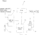
- the measurement unit 2 comprises a specimen preparation unit 21, a detection unit 22 measuring a measurement specimen, an analog processing unit 23 to output of the detection unit 22, a display/operation unit 24, and a micro computer unit 25 for controlling the measurement unit 2.
- the specimen preparation unit 21 is provided for preparing a white blood cell measurement specimen, a reticulocyte measurement specimen and a blood platelet measurement specimen.
- the specimen preparation unit 21 includes a blood collection tube 21a filled with a prescribed amount of blood, a sampling valve 21b sucking blood and a reaction chamber 21c.
- the blood collection tube 21a is enabled to be replaced and exchange blood.
- the sampling valve 21b has a function of determining a prescribed amount of blood of the blood collection tube 21a sucked by a suction pipette (not shown).
- the sampling valve 21b is enabled to mix a prescribed reagent in the sucked blood.
- the sampling valve 21b is enabled to form a diluted specimen mixed with the prescribed amount of reagent supplied from the reagent preparation device 4 to a prescribed amount of blood.
- the reaction chamber 21c is formed to further mix a prescribed stain in the diluted specimen supplied from the sampling valve 21b and react the same for a prescribed time.
- the specimen preparation unit 21 has a function of staining white blood cells and preparing a measurement specimen of hemolyzed red blood cells as a white blood cell measurement specimen.
- the specimen preparation unit 21 has a function of preparing a measurement specimen stained with reticulocytes as a reticulocyte measurement specimen and preparing a measurement specimen stained with blood platelets as a blood platelet measurement specimen.
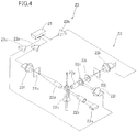
- the specimen preparation unit 21 is so formed as to supply the white blood cell measurement specimen from the specimen preparation unit 21 to a sheath flow cell 22c (see Fig. 4 ), described later, together with a sheath solution in a white blood cell classification measurement (hereinafter referred to as a "DIFF measurement") mode.
- the specimen preparation unit 21 is so formed as to supply the reticulocyte measurement specimen from the specimen preparation unit 21 to the sheath flow cell 22c together with the sheath solution in a reticulocyte measurement (hereinafter referred to as a "RET measurement") mode.
- the specimen preparation unit 21 is so formed as to supply the blood platelet measurement specimen from the specimen preparation unit 21 to the sheath flow cell 22c together with the sheath solution in a blood platelet measurement (hereinafter referred to as a "PLT measurement”) mode.
- the detection unit 22 includes a light emitting unit 22a for emitting a laser beam, an illumination lens unit 22b, the sheath flow cell 22c for applying the laser beam, a condensing lens 22d, a pinhole 22e and a PD (photodiode) 22f arranged on an extension line of a traveling direction of the laser beam emitted from the light emitting unit 22a, a condensing lens 22g, a dichroic mirror 22h, an optical filter 22i, a pinhole 22j and an APD (avalanche photodiode) 22k arranged in a direction intersecting with the traveling direction of the laser beam emitted from the light emitting unit 22a, and a PD 221 arranged in a lateral direction of the dichroic mirror 22h.
- a light emitting unit 22a for emitting a laser beam
- an illumination lens unit 22b for applying the laser beam
- a condensing lens 22d for emitting a laser beam
- the light emitting unit 22a is provided for emitting light with respect to the flow of the specimen including the measurement specimen passing through the inside of the sheath flow cell 22c.
- the illumination lens unit 22b is provided for parallelizing the light emitted from the light emitting unit 22a.
- the PD 22f is provided for receiving forward scattered light emitted from the sheath flow cell 22c. It is possible to obtain information on sizes of the particles (blood cells) in the measurement specimen by the forward scattered light emitted from the sheath flow cell 22c.
- the dichroic mirror 22h is provided for separating lateral scattered light and lateral fluorescence emitted from the sheath flow cell 22c. More specifically, the dichroic mirror 22h is provided for introducing the lateral scattered light emitted from the sheath flow cell 22c into the PD 221 and introducing the lateral fluorescence emitted from the sheath flow cell 22c to the APD 22k.
- the PD 221 is provided for receiving the lateral scattered light. It is possible to obtain inside information such as sizes of nucleuses of the particles (blood cells) in the measurement specimen by the lateral scattered light emitted from the sheath flow cell 22c.
- the APD 22k is provided for receiving the lateral fluorescence.
- the PDs 22f and 221 and the APD 22k have functions of converting the received light signals to electric signals, respectively.
- the analog processing unit 23 includes amplifiers 23a, 23b and 23c.
- the amplifiers 23a, 23b and 23c are provided for executing amplification and waveform processing for the electric signals outputted from the PDs 22f and 221 and the APD 22k, respectively.
- the micro computer unit 25 includes a control unit 251 having a control processor and a memory for operating the control processor, an A-D conversion unit 252 converting a signal outputted from the analog processing unit 23 to a digital signal and an arithmetic unit 253 for performing prescribed processing for the digital signal outputted from the A-D conversion unit 252.
- the control unit 251 has a function of controlling the specimen preparation unit 21 and the detection unit 22 through a bus 254a and an interface 255a.
- the control unit 251 is connected to the display/operation unit 24 through the bus 254a and an interface 255b and connected to the data processing part 3 through a bus 254b and an interface 255c.
- the arithmetic unit 253 has a function of outputting an arithmetic result to the control unit 251 through an interface 255d and the bus 254a.
- the control unit 251 has a function transmitting the arithmetic result (measurement data) to the data processing part 3.
- the data processing part 3 is constituted by a personal computer (PC) or the like, and has a function of analyzing the measurement data of the measurement unit 2 and displaying the results of analysis.
- the data processing part 3 includes a control unit 31, a display unit 32 and an input device 33.
- the control unit 31 has a function of transmitting a measurement start signal including measurement mode information and a shutdown signal to the measurement unit 2.
- the control unit 31 is constituted by a CPU 31a, an ROM 31b, a RAM 31c, a hard disk 31d, a reader 31e, an input/output interface 31f, an image output interface 31g and a communication interface 31i.
- the CPU 31a, the ROM 31b, the RAM 31c, the hard disk 31d, the reader 31e, the input/output interface 31f, the image output interface 31g and the communication interface 31i are connected by a bus 31h.
- the CPU 31a is provided for running computer programs stored in the ROM 31b and computer programs loaded in the RAM 31c.
- the ROM 31b is constituted by a mask ROM, a PROM, an EPROM, an EEPROM or the like, and the computer programs run by the CPU 31a and data employed therefor are recorded therein.
- the RAM 31c is constituted of an SRAM or a DRAM.
- the RAM 31c is employed for reading the computer programs recorded in the ROM 31b and the hard disk 31d. Further, the RAM 31c is utilized as a working area of the CPU 31a when running these computer programs.
- An operating system and various computer programs such as application programs to be run by the CPU 31a as well as data employed for running the computer programs are installed in the hard disk 31d.
- the application program 34a described later is also installed in this hard disk 31d.
- the reader 31e is constituted by a flexible disk drive, a CD-ROM drive or a DVD-ROM drive, and can read computer programs or data recorded in a portable recording medium 34.
- the potable recording medium 34 stores the application program 34a for execution of a prescribed function by the computer, while the computer as the data processing part 3 can read the application program 34a from the portable recording medium 34 and install this application program 34a in the hard disk 31d.
- the aforementioned application program 34a is not only provided by the portable recording medium 34, but can also be provided from an external apparatus communicably connected with the data processing part 3 by an electric communication line (whether wire or wireless) through the aforementioned electric communication line.
- the aforementioned application program 34a is stored in a hard disk of a server computer on the Internet, so that the data processing part 3 accesses this server computer, downloads the application program 34a and installs the same in the hard disk 31d.
- the operating system such as Windows (registered trademark) manufactured and sold by Microsoft, U.S.A., for example, providing graphical user interface environment is installed in the hard disk 31d.
- Windows registered trademark
- U.S.A. graphical user interface environment
- the input interface 31f is constituted by a serial interface such as USB, IEEE 1394 or RS-232C, a parallel interface such as SCSI, IDE or IEEE 1284, an analog interface formed by a D/A converter, an A/D converter etc. or the like, for example.
- the input device 33 constituted by a keyboard and a mouse is connected to the input/output interface 31f, so that the user can input data into the data processing part 3 by using this input device 33 by a user.
- the input device 33 has a function of receiving a measurement mode.
- the image output interface 31g is connected to the display unit 32 constituted by an LCD or a CRT, for outputting an image signal corresponding to image data supplied from the CPU 31a to the display unit 32.
- the display unit 32 displays an image (screen) according to the inputted image signal.
- the reagent preparation device 4 is provided for preparing the reagent employed in the specimen preparation unit 21 of the measurement unit 2. More specifically, the reagent preparation device 4 is so formed as to prepare a reagent employed in blood analysis by diluting the high-concentration reagent with RO water prepared from tap water as a dilution liquid.
- the RO water is water obtained after removing impurities by transmitting through an RO (reverse osmosis) membrane.
- the reagent preparation device 4 includes a reagent constant amount tank 41 for quantifying and supplying the high-concentration reagent from a high-concentration reagent tank 5 storing the high-concentration reagent, an RO water constant amount tank 42 quantifying and supplying the RO water for diluting the high-concentration reagent, a reagent preparation tank 43 storing the high-concentration reagent and the RO water and preparing the reagent employed in blood analysis, an RO water constant amount pump (diaphragm pump) 44, a reagent tank 45 for storing the prepared reagent, an RO water preparation unit 46 preparing the RO water from the tap water, and a control unit 47 controlling an operation of the reagent preparation device 4.
- a reagent constant amount tank 41 for quantifying and supplying the high-concentration reagent from a high-concentration reagent tank 5 storing the high-concentration reagent
- an RO water constant amount tank 42 quantifying and supplying the RO water for diluting the high-concentr
- a pneumatic device 6 (see Fig. 1 ) including positive pressure sources 61 applying positive pressures and negative pressure sources 62 applying negative pressures is provided on an outer portion of the reagent preparation device 4 in order to control movement of each liquid in the device.
- the positive pressure sources 61 and the negative pressure sources 62 are connected to respective prescribed portions of the reagent preparation device 4.
- the reagent constant amount tank 41 is provided with a liquid level sensor SE1 for detecting the amount of the high-concentration reagent in the tank.
- the reagent constant amount tank 41 is connected to the high-concentration reagent tank 5 through an electromagnetic valve V1, and connected to the negative pressure source 62 through an electromagnetic valve V2.
- the electromagnetic valves V1 and V2 are opened, thereby applying a negative pressure to the reagent constant amount tank 41 and supplying the high-concentration reagent from the high-concentration reagent tank 5 to the reagent constant amount tank 41.
- the electromagnetic valves V1 and V2 are closed to stop the supply of the high-concentration reagent.
- the prescribed amount of high-concentration reagent is determined.
- the RO water constant amount tank 42 is provided with a liquid level sensor SE2 for detecting the amount of the RO water in the tank, a conductivity sensor SE3 detecting an electrical conductance of the RO water in the tank, and a temperature sensor SE4 measuring a temperature of the RO water in the tank.
- the RO water constant amount tank 42 is connected to the negative pressure source 62 through an electromagnetic valve V3, and connected to an RO water tank 46a of the RO water preparation unit 46, described later, through an electromagnetic valve V4.
- the electromagnetic valves V3 and V4 are opened, thereby applying a negative pressure to the RO water constant amount tank 42 and supplying the RO water from the RO water tank 46a to the RO water constant amount tank 42.
- the electromagnetic valves V3 and V4 are closed to stop the supply of the RO water.
- the prescribed amount of RO water is determined.
- the reagent constant amount tank 41 is connected to the positive pressure source 61 through an electromagnetic valve V5, and the reagent constant amount tank 41 and the reagent preparation tank 43 are connected to each other through an electromagnetic valve V6.
- the electromagnetic valves V5 and V6 are opened, thereby applying a positive pressure to the reagent constant amount tank 41 and supplying the prescribed amount of high-concentration reagent from the reagent constant amount tank 41 to the reagent preparation tank 43.
- the electromagnetic valves V5 and V6 are closed after the high-concentration reagent in the reagent constant amount tank 41 is supplied to the reagent preparation tank 43.
- the RO water constant amount tank 42 is connected to the positive pressure source 61 through an electromagnetic valve V7, and the RO water constant amount tank 42 and the reagent preparation tank 43 are connected to each other through an electromagnetic valve V8.
- the electromagnetic valves V7 and V8 are opened, thereby applying a positive pressure to the RO water constant amount tank 42 and supplying the prescribed amount of RO water from the RO water constant amount tank 42 to the reagent preparation tank 43.
- the electromagnetic valves V7 and V8 are closed after the RO water in the RO water constant amount tank 42 is supplied to the reagent preparation tank 43.
- the reagent preparation device 4 is so formed that the high-concentration reagent is diluted by 25 times by the RO water in the reagent preparation tank 43. More specifically, the RO water is supplied from the RO water constant amount tank 42 to the reagent preparation tank 43 and the high-concentration reagent is supplied from the reagent constant amount tank 41 to the reagent preparation tank 43 so that the mixing ratio of the high-concentration reagent and the RO water in the reagent preparation tank 43 is 1:24 (dilution magnification: 25 times).
- the reagent preparation tank 43 is provided with a stirring unit 43a mixing and stirring the supplied high-concentration reagent and RO water, and the stirring unit 43a is driven by a motor 43b.
- the reagent preparation tank 43 is further provided with two conductivity sensors SE 5 and SE6 detecting the electrical conductance of the reagent obtained by mixing and stirring the high-concentration reagent and the RO water by the stirring unit 43a, and a temperature sensor SE7 measuring the temperature of the reagent obtained by mixing and stirring the high-concentration reagent and the RO water by the stirring unit 43a.
- the conductivity sensors SE 5 and SE6 are arranged on respective different positions in the reagent preparation tank 43.
- the RO water constant amount pump (diaphragm pump) 44 has a function of discharging the RO water, and is enabled to gradually supply the prescribed amount of RO water to the reagent preparation tank 43 in order to dilute the reagent in the reagent preparation tank 43 at a desired concentration.
- the RO water constant amount pump 44 is connected to the negative pressure source 62 through an electromagnetic valve V9.
- the electromagnetic valves V7 and V9 are opened, thereby applying a negative pressure to the RO water constant amount pump 44, applying a positive pressure to the RO water constant amount tank 42, and supplying the RO water from the RO water constant amount tank 42 to the RO water constant amount pump 44.
- the RO water constant amount pump 44 is connected also to the positive pressure source 61 through an electromagnetic valve V10, and the reagent preparation tank 43 is provided with an electromagnetic valve V11 so as to open to the atmosphere.
- the electromagnetic valves V10 and V11 are opened, thereby applying a positive pressure to the RO water constant amount pump 44 and supplying the prescribed amount of RO water from the RO water constant amount pump 44 to the reagent preparation tank 43.
- the reagent preparation tank 43 and the reagent tank 45 are connected to each other through an electromagnetic valve V12.
- the electromagnetic valves V11 and V12 are opened, so that a pressure in the reagent preparation tank 43 is opened to the atmosphere and the reagent diluted at the desired concentration is supplied from the reagent preparation tank 43 to the reagent tank 45 provided below the reagent preparation tank 43.
- the reagent tank 45 is provided with a liquid level sensor SE8 for detecting the amount of the reagent in the tank.
- the control unit 47 determines whether or not the reagent is newly prepared at a desired concentration on the basis of a detection result of the liquid level sensor SE8.
- the reagent tank 45 is connected to the measurement unit 2 and is enabled to supply the reagent in the reagent preparation tank 45 to the measurement unit 2.
- the RO water preparation unit 46 is enabled to prepare the RO water as the dilution liquid for diluting the high-concentration reagent with the tap water. Thus, no device for preparing the RO water other than the reagent preparation device 4 may be separately provided.
- the RO water preparation unit 46 includes the RO water tank 46a, an RO membrane 46b, a filter 46c protecting the RO membrane 46b by removing impurities containing the tap water, a high-pressure pump 46d applying a high pressure to water passing through the filter 46c so as to transmit water molecules through the RO membrane 46b, and an electromagnetic valve V13 controlling supply of the tap water.
- the RO water tank 46a is provided for storing the RO water transmitted through the RO membrane 46b.
- the RO water tank 46a is provided with a liquid level sensor SE9 for detecting the amount of RO water in the tank, and the RO water is prepared on the basis of a detection result of the liquid level sensor SE9.
- a prescribed amount of RO water can be always ensured in the RO water tank 46a.
- the electromagnetic valve V13 is first opened and the tap water reaches the filter 46c.
- the water transmitted through the filter 46c is applied with a pressure by the high-pressure pump 46d to transmit the water through the RO membrane 46b, and RO water transmitted through the RO membrane 46b is supplied to the storage tank 46a. Water containing impurities, not transmitted through the RO membrane 46b is discharged outside the reagent preparation device 4.
- control unit 47 includes a CPU 47a, an ROM 47b, a RAM 47c, and a communication interface 47d connected to the data processing part 3, and an I/O (input/output) unit 47e connected to respective portions in the reagent preparation device 4.
- the CPU 47a is provided for running computer programs stored in the ROM 47b and computer programs loaded in the RAM 47c. Further, the RAM 47c is utilized as a working area of the CPU 47a when running these computer programs.
- the CPU 47a detects the electrical conductance of the RO water in the RO water constant amount tank 42 by the conductivity sensor SE3 and stores a detection value Y1 in the RAM 47c.
- the CPU 47a is so formed as to measure the temperature of the RO water in the RO water constant amount tank 42 by the temperature sensor SE4 and also store a measurement value T1 in the RAM 47c.
- the CPU 47a so drives the stirring unit 43a by the motor 43b that a detection value YS5 detected by a conductivity sensor SE5 provided in the reagent preparation tank 43 and a detection value YS6 detected by the conductivity sensor SE6 are substantially the same. More specifically, the CPU 47a determines whether or not an absolute value
- a detection value YS5 detected by a conductivity sensor SE5 provided in the reagent preparation tank 43 a detection value YS6 detected by the conductivity sensor SE6 are substantially the same. More specifically, the CPU 47a determines whether or not an absolute value
- the CPU 47a detects the electrical conductance of the reagent in the reagent preparation tank 43 with the conductivity sensor SE5, and stores a detection value Y2 at that time in the RAM 47c. At this time, the CPU 47a also measures the temperature of the reagent in the reagent preparation tank 43 with the temperature sensor SE7, and stores a measurement value T2 in the RAM 47c.
- the CPU 47a so supplies the RO water to the reagent preparation tank 43 with the RO water constant amount tank 42 (also with the RO water constant amount pump 44, if necessary) that the detection value Y2 by the conductivity sensor SE5 is in a prescribed range with respect to a target value Z of an electrical conductance for diluting the high-concentration reagent at the desired concentration.
- Z 0 represents a target value (ms/cm) of an electrical conductance at 25 °C of the reagent obtained by mixing and stirring the high-concentration reagent and the RO water
- X represents an electrical conductance (ms/cm) at 25 °C of the high-concentration reagent
- Y represents an electrical conductance (ms/cm) at 25 °C of the RO water
- A represents a (known) dilution magnification (25 times in the first embodiment).
- the X is a value inherent to the high-concentration reagent and a known value previously obtained by an experiment or the like.
- a compensation formula for considering the temperature of the RO water and change in the temperature of the reagent obtained by mixing and stirring the high-concentration reagent and the RO water is expressed by the following formula (2):
- Z represents a target value (ms/cm) of an electrical conductance at T2 °C of the reagent obtained by mixing and stirring the high-concentration reagent and the RO water
- Y1 represents an electrical conductance (ms/cm) at T1 °C of the RO water
- T1 is a temperature (°C) of the RO water
- T2 is a temperature (°C) of the reagent obtained by mixing and stirring the high-concentration reagent and the RO water
- ⁇ 0 represents a temperature coefficient with respect to 25 °C
- the CPU 47a is formed to calculate the target value Z by the aforementioned formula (2). Therefore, the CPU 47a decides the target value on the basis of the desirable (known) dilution magnification A, the detection value Y1 of the electrical conductance of the RO water, the measurement value T1 of the temperature of the RO water, the measurement value T2 of the temperature of the mixed and stirred reagent and the (known) electrical conductance X of the high-concentration reagent.
- the communication interface 47d is enabled to transmit error information to the data processing part 3 so that a user can easily recognize an error caused in the reagent preparation device 4.
- An error notification is displayed on the display unit 32 of the data processing part 3 on the basis of this error information.
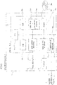
- the I/O unit 47e is so formed that signals are inputted from the respective sensor SE1 to S9 through the respective sensor circuits, as shown in Fig. 7 .
- the I/O unit 47e is so formed as to output signals of respective drive circuits in order to control drive of the electromagnetic valves V1 to V13, the motor 43b and the high-pressure pump 46d through the respective drive circuits.
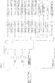
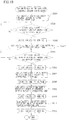
- a reagent preparation processing operation of the blood analysis device 1 according to the first embodiment of the present invention will be now described with reference to Figs. 6 and 8 .
- the CPU 47a first initializes the computer programs stored in the ROM 47b.
- the CPU 47a determines whether or not the liquid level sensor SE9 provided in the RO water tank 46a has detected a liquid. If the liquid level sensor SE9 has not detected the liquid, namely, if the prescribed amount of RO water is not stored in the RO water tank 46a, the CPU 47a performs RO water preparation processing with the RO water preparation unit 46 at a step S3. The RO water preparation processing at the step S3 will be described later. If the liquid level sensor SE9 has detected the liquid, the CPU 47a determines whether or not the liquid level sensor SE8 of the reagent tank 45 has detected at a step S4.
- the liquid level sensor SE8 If the liquid level sensor SE8 has detected the liquid, namely, if the prescribed amount of reagent is stored in the reagent tank 45, the prescribed amount of reagent for using in the measurement unit 2 is ensured, and hence the process advances to a step S15 without newly preparing a reagent. If the liquid level sensor SE8 has not detected the liquid, the CPU 47a performs processing for supplying the high-concentration reagent and the RO water to the reagent preparation tank 43 at a step S5 in order to newly prepare the reagent. The processing for supplying the high-concentration reagent and the RO water at the step S5 will be described later.
- the CPU 47a mixes and stirs the high-concentration reagent and the RO water supplied to the reagent preparation tank 43 with the stirring unit 43a.
- the CPU 47a detects the electrical conductance YS5 of the reagent in the reagent preparation tank 43 with the conductivity sensor SE5, and detects the electrical conductance YS6 of the reagent in the reagent preparation tank 43 with the conductivity sensor SE6.
- the CPU 47a determines whether or not the absolute value
- the CPU 47a measures the temperature T2 of the reagent in the reagent preparation tank 43 at that time with the temperature sensor SE7, and detects the electrical conductance Y2 of the reagent with the conductivity sensor SE5 at a step S9.
- the CPU 47a stores the measurement value T2 and the detection value Y2 in the RAM 47c at a step S10, and the target value Z of the electrical conductance of the reagent in the reagent preparation tank 43 is calculated by the aforementioned formula (2) at a step S11.
- the CPU 47a determines whether or not difference between the target value Z and the detection value Y2 (Z-Y2) is larger than a prescribed value N1 (negative value). If the difference (Z-Y2) is smaller than the prescribed value N1, the RO water must be further supplied to the reagent preparation tank 43, and hence the electromagnetic valves V7 and V9 are opened in order to supply the RO water to the RO water constant amount pump 44 at a step S17.
- the CPU 47a After supplying the RO water to the RO water constant amount pump 44, the CPU 47a closes the electromagnetic valves V7 and V9 at a step S18 and opens the electromagnetic valves V10 and V11 at a step S19, so that the prescribed amount of RO water is additionally supplied from the RO water constant amount pump 44 to the reagent preparation tank 43.
- the electrical conductance of the reagent in the reagent preparation tank 43 varies due to additional supply of the RO water, and hence the process advances to the step S6, and mixing and stirring are performed again.
- the CPU 47a determines whether or not the difference (Z-Y2) is smaller than a prescribed value N2 at the step S13. If the difference (Z-Y2) is larger than the prescribed value N2, the concentration of the reagent in the reagent preparation tank 43 is lower than the desired concentration, and hence the CPU 47a transmits warning information showing that the reagent with the desired concentration has not been prepared to the data processing part 3 through the communication interface 47d at a step S20.
- the CPU 31a of the data processing part 3 has received the aforementioned warning information through the communication interface 31i, a massage that the reagent with the desired concentration has not been prepared in the reagent preparation device 4 is displayed on the display unit 32.
- the CPU 47a opens the electromagnetic valves V11 and V14 to discharge the reagent in the reagent preparation tank 43 outside the reagent preparation device 4.
- the CPU 47a closes the electromagnetic valves V11 and V14 at a step S22.
- the CPU 47a opens the electromagnetic valves V11 and V12 and the reagent prepared to have the electrical conductance which is substantially the same as the target value Z is supplied to the reagent tank 45 at a step S14.
- the reagent diluted at the desired concentration is stored in the reagent tank 45.
- the CPU 47a closes the electromagnetic valves V11 and V12 at the step S15 and determines whether or not a shutdown instruction of the reagent preparation device 4 has been made at a step S16. If the shutdown instruction has been made, an operation of the reagent preparation device 4 ends. If the shutdown instruction has not been made, the process advances to the step S2.
- the CPU 47a opens the electromagnetic valve V13 to transmit the tap water through the filter 46c at a step S301 in Fig. 9 .
- the CPU 47a drives the high-pressure pump 46d to transmit the water transmitted through the filter 46c through the RO membrane 46b by a high pressure.
- the CPU 47a determines whether or not the liquid level sensor SE9 of the RO water tank 46a has detected the liquid. In other words, the CPU 47a determines whether or not the prescribed amount RO water is stored in the RO water tank 46a. If the liquid level sensor SE9 has not detected the liquid, this determination is repeated, and the RO water transmitted through the RO membrane 46b is continuously supplied to the RO water tank 46a. On the other hand, if the liquid level sensor SE9 has detected the liquid, the CPU 47a closes the electromagnetic valve V13, stops the drive of the high-pressure pump 46d, and ends the operation at a step S304.
- the CPU 47a opens the electromagnetic valves V1 and V2 and the high-concentration reagent is supplied from the high-concentration reagent tank 5 to the reagent constant amount tank 41 at a step S501 in Fig. 10 .
- the CPU 47a determines whether or not the liquid level sensor SE1 of the reagent constant amount tank 41 has detected the liquid. In other words, the CPU 47a determines whether or not the prescribed amount of high-concentration reagent has been supplied to the reagent constant amount tank 41. If the liquid level sensor SE1 has not detected the liquid, this determination is repeated until the liquid level sensor SE1 detects the liquid.
- the CPU 47a closes the electromagnetic valves VI and V2 in order to stop the supply of the high-concentration reagent from the high-concentration reagent tank 5 at a step S503.
- the CPU 47a opens the electromagnetic valves V3 and V4, and the RO water is supplied from the RO water tank 46a to the RO water constant amount tank 42.
- the CPU 47a determines whether or not the liquid level sensor SE2 of the RO water constant amount tank 42 has detected the liquid. In other words, the CPU 47a determines whether or not the prescribed amount of RO water has been supplied to the RO water constant amount tank 42. If the liquid level sensor SE2 has not been detected the liquid, the RO water is continuously supplied to the RO water constant amount tank 42 until the liquid level sensor SE2 detects the liquid.
- the CPU 47a closes the electromagnetic valves V3 and V4 and the supply from the RO water tank 46a to the RO water constant amount tank 42 ends at a step S506.
- the CPU 47a measures the temperature T1 of the RO water in the RO water constant amount tank 42 with the temperature sensor SE4, and detects an the electrical conductance Y1 of the RO water with the conductivity sensor SE3.
- the CPU 47a stores the aforementioned measurement value T1 and detection value Y1 in the RAM 47c.
- the CPU 47a opens the electromagnetic valves V5 and V6 and supplies the prescribed amount of high-concentration reagent from the reagent constant amount tank 41 to the reagent preparation tank 43 at a step S509, and the electromagnetic valves V5 and V6 are closed at a step S510.
- the CPU 47a opens the electromagnetic valves V7 and V8 and supplies the prescribed amount of RO water from the RO water constant amount tank 42 to the reagent preparation tank 43 at a step S511, the CPU 47a closes the electromagnetic valves V7 and V8 at a step S512, and the operation ends.
- the control unit 47 decides the target value Z of the electrical conductance of the reagent obtained by mixing and stirring the high-concentration reagent and the RO water on the basis of the detection value Y1 detected by the conductivity sensor SE3 detecting the electrical conductance of the RO water, and so controls the supply operation of the RO water constant amount pump 44 that the detection value Y2 detected by the conductivity sensor SE5 detecting the electrical conductance of the reagent obtained by mixing and stirring the high-concentration reagent and the RO water approaches the target value Z.
- the target value Z is decided on the basis of a varied value also when the electrical conductance of the RO water varies, and the electrical conductance of the reagent obtained by mixing and stirring the high-concentration reagent and the RO water can approach the target value Z. Consequently, the high-concentration reagent can be diluted at the desired concentration.
- the blood analysis device 1 is provided with the conductivity sensor SE3 detecting the electrical conductance of the RO water, the temperature sensor SE4 measuring the temperature of the RO water, the conductivity sensor SE5 detecting the electrical conductance of the reagent obtained by mixing and stirring the high-concentration reagent and the RO water, and the temperature sensor SE7 measuring the temperature of the reagent obtained by mixing and stirring the high-concentration reagent and the RO water, and the control unit 47 decides the target value Z of the electrical conductance of the reagent obtained by mixing and stirring the high-concentration reagent and the RO water on the basis of the (known) desired dilution magnification A, the detection value Y1 detected by the conductivity sensor SE3, the measurement value T1 measured by the temperature sensor SE4, and the measurement value T2 measured by the temperature sensor SE7 and the (known) electrical conductance X of the high-concentration reagent.
- the target value Z of the electrical conductance of the reagent obtained by mixing and stirring the high-concentration reagent and the RO water is decided on the basis of not only the electrical conductance Y1 of the RO water but also the temperatures T1 and T2 correlated with the electrical conductance, and hence the high-concentration reagent can be precisely diluted at the desired concentration.
- the control unit 47 so controls the supply operation of the RO water constant amount pump 44 that a smaller amount of the RO water than the mixing amount on the basis of the mixing ratio (1:24) among the high-concentration reagent and the RO water is supplied to the reagent preparation tank 43 and the RO water is additionally gradually supplied to the reagent preparation tank 43 so as for the detection value Y2 detected by the conductivity sensor SE5 to approach the target value Z, whereby the amount of change of the electrical conductance of the reagent in the reagent preparation tank 43 can be reduced as compared with a case where the high-concentration reagent is additionally gradually supplied.
- the electrical conductance Y2 of the reagent in the reagent preparation tank 43, detected by the conductivity sensor SE5 can precisely approach the target value Z while changing the amount of the electrical conductance Y2 little by little.
- a blood analysis device 100 according to a second embodiment of the present invention will be now described with reference to Figs. 12 and 13 .
- the blood analysis device 100 according to the second embodiment is so formed that information on maintenance of a reagent preparation device 104, information on a state of reagent preparation or the like is displayed on a display unit 32 of a data processing part 3 dissimilarly to the aforementioned blood analysis device 1 according to the first embodiment.
- a case where the present invention is applied to the blood analysis device 100 which is an exemplary sample analysis system will be described.
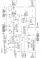
- the blood analysis device 100 is constituted by a measurement unit 2, the data processing part 3 and the reagent preparation device 104, as shown in Fig. 12 .
- the data processing part 3 has a communication interface 31i connected to a server computer 300 through a network 200.
- the data processing parts 3 of a plurality of the blood analysis devices 100 are connected to the server computer 300 through the network 200.
- the reagent preparation device 104 is provided with a conductivity sensor SE10 detecting an electrical conductance of RO water to an RO water tank 46a in addition to a structure of a reagent preparation device 4 of the aforementioned first embodiment, as shown in Fig. 13 .
- the RO water tank 46a is enabled to discharge the RO water in the tank through an electromagnetic valve V15.
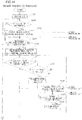
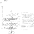
- FIG. 14 to 16 A reagent preparation processing operation of the blood analysis device 100 according to the second embodiment of the present invention will be now described with reference to Figs. 14 to 16 .
- steps S1 to S22 shown in Figs. 14 to 16 operations similarly to those at the step S1 to step S22 shown in Fig. 8 respectively are performed, and therefore the description thereof will not be made in the following.
- the CPU 47a determines whether or not it is time for maintenance of the reagent preparation device 104 at a step S201. For example, a filter 46c of an RO water preparation unit 46 is set to be replaced once every six months, an RO membrane 46b is set to be replaced once every one to two years, and cleaning of the RO water preparation unit 46 is set to be performed once every twelve weeks. If it is not the time for maintenance, the process advances to the step S2. On the other hand, if it is the time for maintenance, message display instruction information requiring maintenance execution is transmitted to the data processing part 3 through a communication interface 47d at a step S202.
- the CPU 31a determines whether or not data communication has been performed. More specifically, it is determined whether or not the message display instruction information such as maintenance execution request transmitted from the reagent preparation device 104 has been received through the communication interface 31i. This determination is repeated until the message display instruction information is received.
- the received information is based on the maintenance execution request at a step S602, and the maintenance request screen is displayed on the display unit 32 at a step S603. More specifically, if the contents of the maintenance are replacement of the filter 46c and the RO membrane 46b, a maintenance request screen 320 of the filter 46c and the RO membrane 46b is displayed on the display unit 32, as shown in Fig. 18 . A message stating that "it is time for maintenance of the filter/RO membrane” showing necessity of the maintenance of the filter 46c and the RO membrane 46b is displayed on the maintenance request screen 320. A message stating that "please press an OK bottom after replacement of the filter/RO membrane” facilitating the replacement of the filter 46c and the RO membrane 46b is also displayed on the maintenance request screen 320. An OK button 320a for receiving a maintenance processing instruction is further displayed on the maintenance request screen 320.
- a step S604 it is determined whether or not the maintenance processing instruction has been received on the basis of a state of press of the OK button 320a, and this determination is repeated until the OK button 320a is pressed.
- the maintenance processing instruction information is transmitted to the reagent preparation device 104 at a step S605.
- the CPU 47a determines whether or not the maintenance processing instruction information transmitted from the data processing part 3 has been received at a step S203. This determination is repeated until the maintenance processing instruction information is received, and when received, maintenance processing is performed at a step S204. More specifically, the replacement processing of the filter 46c and the RO membrane 46b, the cleaning processing of the RO water preparation unit 46 or the like is performed in response to the contents of the maintenance.
- the CPU 47a determines whether or not the tap water is supplied to the RO water preparation unit 46 at a step S205. If it is supplied, RO water preparation processing is performed at the step S3.
- the conductivity sensor SE10 measures the electrical conductance of the RO water in the tank at a step S305.
- a measurement result of the electrical conductance as water quality information is transmitted to the data processing part 3 through the communication interface 47d, and the RO water preparation processing operation ends.
- the received information is water quality information at a step S614 after determination of steps S601, S602, S606 and S610 shown in Fig. 17 .
- the received water quality information is transmitted to the server computer 300 through the network 200.
- the transmitted water quality information is stored in the server computer 300, and thereafter employed as information for determining the contents of a failure caused in the RO water preparation unit 46.
- a plurality of the water quality information obtained from a plurality of the blood analysis devices 100 connected through the network 200 is stored in the server computer 300, and the contents of a failure of the RO water preparation unit 46 can be determined with these plurality of water quality information.
- the received information in the data processing part 3 is not any of information based on the maintenance execution request, the RO water supply impossibility, the high-concentration reagent replacement and the water quality information, other processing in response to the received information, such as message display showing other failure caused in the reagent preparation device 104 is performed at a step S616.
- an RO water supply impossible screen 321 is displayed on the display unit 32, as shown in Fig. 20 .
- a message stating that "RO water is not supplied” showing an RO water supply impossible state is displayed on the RO water supply impossible screen 321.
- a message stating that "please press an OK bottom after turning a faucet on” facilitating supply of the tap water in order to solve this state is also displayed on the RO water supply impossible screen 321.
- An OK button 321a for receiving a return processing instruction of the RO water preparation processing operation is further displayed on the maintenance request screen 320.
- a step S608 it is determined whether or not the return processing instruction has been received on the basis of a state of press of the OK button 321a, and this determination is repeated until the OK button 321a is pressed.
- the return processing instruction information is transmitted to the reagent preparation device 104 at a step S609.
- the reagent preparation device 104 After transmitting the display instruction information of the message showing the RO water supply impossibility has been transmitted to the data processing part 3 at the step S206 in Fig. 14 , it is determined whether or not the return processing instruction information transmitted from the data processing part 3 has been received at a step S207. This determination is repeated until the return processing instruction information is received. If it is received, the return processing of the RO water preparation processing operation is performed at a step S208. More specifically, all of the RO water stored in the RO water tank 46a is discharged by opening the electromagnetic valve V15.
- step S4 if it is determined that the prescribed amount of reagent is not stored in the reagent tank 45, it is determined whether or not the high-concentration reagent can be supplied from the high-concentration reagent tank 5 to the reagent constant amount tank 41 at a step S209. If it can be supplied, an supply processing operation of the high-concentration reagent and the RO water is performed at the step S5. On the other hand, if it can not be supplied, the display instruction information of the message facilitating replacement of the high-concentration reagent tank 5 is transmitted to the data processing part 3 through the communication interface 47d at a step S210.
- the display instruction information of the message facilitating the replacement of the high-concentration reagent tank 5 is transmitted from the reagent preparation device 104, in the data processing part 3, it is determined that the received information is information for facilitating the replacement of the high-concentration reagent tank 5 at a step S610 after determination of the steps S601, S602 and S 606 shown in Fig. 17 .
- a high-concentration reagent replacement screen 322 is displayed on the display unit 32, as shown in Fig. 21 .
- a message stating that "high-concentration reagent is not supplied" showing a high-concentration reagent supply impossible state is displayed on the high-concentration reagent replacement screen 322.
- a message stating that "please press an OK bottom after replacement of the high-concentration reagent" facilitating replacement of the high-concentration reagent tank 5 in order to solve this state is also displayed on the high-concentration reagent replacement screen 322.
- An OK button 322a for receiving an instruction of tank replacement processing for performing reagent preparation with the replaced high-concentration reagent is further displayed on the high-concentration reagent replacement screen 322.
- a step S612 it is determined whether or not the replacement processing instruction has been received on the basis of a state of press of the OK button 322a, and this determination is repeated until the OK button 322a is pressed.
- the return processing instruction information is transmitted to the reagent preparation device 104 at a step S613.
- the reagent preparation device 104 After transmitting the display instruction information of the message facilitating the replacement of the high-concentration reagent tank 5 to the data processing part 3 at the step S210 in Fig. 15 , it is determined whether or not the replacement processing instruction information transmitted from the data processing part 3 has been received at a step S211. This determination is repeated until the replacement processing instruction information is received.
- the replacement processing of the high-concentration reagent tank 5 is performed at a step S212. More specifically, the electromagnetic valves V1 and V2 are opened, and the high-concentration reagent is supplied from the high-concentration reagent tank 5 to the reagent constant amount tank 41. Then, the operation advances to the step S4.
- the remaining structure of the blood analysis device 100 according to the second embodiment is similar to that of the blood analysis device 1 of the aforementioned first embodiment.
- the reagent preparation device 104 is provided with the CPU 47a detecting the state of the reagent preparation device 104 and the state of the reagent preparation and the communication interface 47d for transmitting the state information detected by the CPU 47a to the data processing part 3 provided outside the reagent preparation device 104, and the data processing part 3 is so formed as to receive the state information transmitted from the reagent preparation device 104 and display the received state information on the display unit 32, whereby the state of the reagent preparation device 104, the state of the reagent preparation or the like can be confirmed by the display unit 32 of the data processing part 3, and hence the situation of the reagent preparation device 104 can be easily visually recognized.
- the data processing part 3 is so formed as to display the information for solving the state of the reagent preparation (the RO water supply impossible state and the high-concentration reagent supply impossible state) in the reagent preparation device 104 on the display unit 32, whereby the user can be easily recognized a method for solving the failure of the reagent preparation on the basis of the information displayed on the display unit 32, and hence the failure can be easily handled.
- the OK buttons 320a, 321a and 322a receiving the operation instructions (the maintenance processing instruction, the return processing instruction and the replacement processing instruction) for the reagent preparation device 104 are displayed on the display unit 32, and the data processing part 3 is so formed that the operation instruction information based on the received operation instruction is transmitted to the reagent preparation device 104, and the reagent preparation device 104 is so formed as to perform the operations (the maintenance processing, the return processing and the replacement processing) according to the received operation instruction information, whereby the user can easily perform a prescribed operation instruction for the reagent preparation device 104 by an easy operation from the display unit 32.
- the CPU 47a determines whether or not the difference (Z-Y2) between the target value Z of the electrical conductance and the detection value Y2 is larger than the prescribed value N1 at the step S12 of the reagent preparation processing operation shown in Fig. 8 , and if the difference (Z-Y2) is smaller than the prescribed value N1, the RO water is additionally supplied to the reagent preparation tank 43 by the RO water constant amount pump 44 at the steps S17 to 19 in the aforementioned first embodiment, the present teaching is not restricted to this.
- a reagent preparation processing operation of a blood analysis device according to another embodiment not being part of the present invention will be hereinafter described.
- processing similar to the processing at the steps S1 to 11 shown in Fig. 8 is performed at steps S101 to 111 by a CPU 47a.
- the CPU 47a determines whether or not an absolute value
- a message stating that the reagent with the desired concentration has not been prepared in a reagent preparation device 4 is displayed on a display unit 32.
- the user can easily know that the reagent has not been prepared at the desired concentration.
- electromagnetic valves V11 and V14 are opened by the CPU 47a of the reagent preparation device 4, and the reagent in the reagent preparation tank 43 is discharged outside the reagent preparation device 4. Then, the CPU 47a closes the electromagnetic valves V11 and V14 at a step S118 after discharging the reagent in the reagent preparation tank 43 outside the reagent preparation device 4.
- the reagent in the reagent preparation tank 43 is prepared at the desired concentration, and hence processing similar to the processing at the steps S14 to S16 shown in Fig. 8 is performed at steps S113 to S115 by the CPU 47a.
- the reagent preparation processing operation according to another embodiment of the present invention is performed in the aforementioned manner.
- the present invention is not restricted to this but is also applicable to an immunoanalyzer or a biochemical analyzer.
- sample processing device and sample analysis system such as a smear preparation device may be applicable so far as it is a sample processing device and a sample analysis system each performing sample processing with a reagent.
- the target value of the electrical conductance of the reagent obtained by mixing and stirring the high-concentration reagent and the RO water is decided according to the aforementioned formula (2)
- the present teaching is not restricted to this but the target value may be decided with a table in which the electrical conductance of the RO water and the target value of the electrical conductance of the liquid obtained by mixing and stirring the high-concentration reagent and the RO water are correspond to each other, for example.
- the conductivity sensor SE3 detecting the electrical conductance of the RO water is provided in the RO water constant amount tank 42 and the conductivity sensor SE5 detecting the electrical conductance of the liquid obtained by mixing and stirring the high-concentration reagent and the RO water is provided in the reagent preparation tank 43 in the aforementioned first embodiment
- the present teaching is not restricted to this but the reagent preparation device 4 may be so formed as to supply the high-concentration reagent into the reagent preparation tank 43 after supplying the RO water into the reagent preparation tank 43, and the conductivity sensor provided in the reagent preparation tank 43 may detect the electrical conductance of the RO water, and then the electrical conductance of the liquid obtained by mixing and stirring the high-concentration reagent and the RO water may be detected.
- the electrical conductance of the RO water and the electrical conductance of the liquid obtained by mixing and stirring the high-concentration reagent and the RO water can be detected simply by providing the one conductivity sensor in the reagent preparation tank 43.
- the structure of the reagent preparation device 4 can be simplified.
- the present teaching is not restricted to this but a high-concentration reagent constant amount pump capable of additionally gradually supplying the high-concentration reagent to the reagent preparation tank may be provided, and the high-concentration reagent may be additionally gradually supplied to the reagent preparation tank by the high-concentration reagent constant amount pump when the concentration of the reagent in the reagent preparation tank 43 is lower than the desired concentration.
- a high-concentration reagent constant amount pump capable of additionally gradually supplying the high-concentration reagent to the reagent preparation tank may be provided, and the high-concentration reagent may be additionally gradually supplied to the reagent preparation tank by the high-concentration reagent constant amount pump when the concentration of the reagent in the reagent preparation tank 43 is lower than the desired concentration.
- the present teaching is not restricted to this but an alarm showing that the reagent has not been prepared at the desired concentration may be emitted from the reagent preparation device 4.
- the reagent preparation device 4 may comprises a display, and a message stating that the reagent with the desired concentration has not been prepared may be displayed on the display of the reagent preparation device 4. The user can easily know that the reagent has not been prepared at the desired concentration also by this.
- control unit 47 provided in the reagent preparation device 4 performs the decision processing deciding the target value of the electrical conductance of the liquid obtained by mixing and stirring the high-concentration reagent and the dilution liquid and the determination processing determining whether or not the electrical conductance detected by the conductivity sensor SE5 is in the prescribed range with respect to the target value in the aforementioned first embodiment
- the present teaching is not restricted to this but the control unit 31 provided in the data processing part 3 may perform the aforementioned decision and determination processing.
- the present invention is not restricted to this but the message showing the high-concentration reagent supply impossible state, the message facilitating the replacement of the high-concentration reagent, the OK button as the preparation instruction receiving screen may be displayed on respective separate display screens.
- the present invention is not restricted to this but the message showing the necessity of the maintenance, the message facilitating execution of the maintenance and the OK button as the maintenance instruction receiving screen may be displayed on respective separate display screens.
Landscapes
- Engineering & Computer Science (AREA)
- Quality & Reliability (AREA)
- General Health & Medical Sciences (AREA)
- General Physics & Mathematics (AREA)
- Life Sciences & Earth Sciences (AREA)
- Chemical & Material Sciences (AREA)
- Analytical Chemistry (AREA)
- Biochemistry (AREA)
- Physics & Mathematics (AREA)
- Health & Medical Sciences (AREA)
- Immunology (AREA)
- Pathology (AREA)
- Automatic Analysis And Handling Materials Therefor (AREA)
- Accessories For Mixers (AREA)
- Feeding, Discharge, Calcimining, Fusing, And Gas-Generation Devices (AREA)
- Investigating Or Analysing Biological Materials (AREA)
- Sampling And Sample Adjustment (AREA)
Claims (14)
- Probenanalysesystem (1), das Folgendes umfasst:eine Reagenzherstellungseinheit (4) zum Herstellen eines Reagenz, das in einer Probenmessung verwendet wird, indem ein Reagenz mit hoher Konzentration mit einer Verdünnungsflüssigkeit verdünnt wird;ein Datenverarbeitungsteil (3); undeine Messeinheit (2), die mit der Reagenzherstellungseinheit verbunden ist, und zum Messen einer Probe mit dem Reagenz, das von der Reagenzherstellungseinheit hergestellt wird, wobeidie Reagenzherstellungseinheit eine Zustandserfassungseinheit beinhaltet, die mindestens einen Zustand der Reagenzherstellungseinheit erfasst, und eine Übertragungseinheit (47d), um Zustandsinformationen, die von der Zustandserfassungseinheit erfasst werden, zu dem Datenverarbeitungsteil (3), das außerhalb der Reagenzherstellungseinheit eingerichtet ist, zu übertragen,wobei das Datenverarbeitungsteil (3) konfiguriert ist, um die Zustandsinformationen, die von der Übertragungseinheit der Reagenzherstellungseinheit übertragen werden, zu empfangen, ein Display (32) beinhaltet und konfiguriert ist, um die empfangenen Zustandsinformationen auf dem Display anzuzeigen, dadurch gekennzeichnet, dass:
das Datenverarbeitungsteil (3) konfiguriert ist, um einen Anweisungsempfangsbildschirm (320, 321, 322) anzuzeigen, um von einem Benutzer eine Betriebsanweisung zu der Reagenzherstellungseinheit auf dem Display zu empfangen und die Betriebsanweisungsinformationen, die auf der empfangenen Betriebsanweisung basieren, zu der Reagenzherstellungseinheit zu übertragen, wenn die Betriebsanweisung vom Anweisungsempfangsbildschirm empfangen wird, und die Reagenzherstellungseinheit (4) konfiguriert ist, um die Betriebsanweisungsinformationen, die von dem Datenverarbeitungsteil übertragen werden, zu empfangen und einen Betrieb der Reagenzherstellungseinheit in Übereinstimmung mit den empfangenen Betriebsanweisungsinformationen zu steuern. - Probenanalysesystem nach Anspruch 1, wobei das Datenverarbeitungsteil (3) konfiguriert ist, um ein Messresultat durch die Messeinheit auf dem Display anzuzeigen, das die Zustandsinformationen, die von der Übertragungseinheit der Reagenzherstellungseinheit übertragen werden, empfängt und die empfangenen Zustandsinformationen auf dem Display anzeigt.
- Probenanalysesystem nach Anspruch 1, wobei
die Zustandserfassungseinheit der Reagenzherstellungseinheit konfiguriert ist, um einen Zustand, in dem eine Zufuhr von Reagenz mit hoher Konzentration unmöglich ist, in dem das Reagenz mit hoher Konzentration nicht zu der Reagenzherstellungseinheit zugeführt wird, zu erfassen,
wobei die Übertragungseinheit der Reagenzherstellungseinheit konfiguriert ist, um Informationen, die den Zustand zeigen, in dem eine Zufuhr von Reagenz mit hoher Konzentration unmöglich ist, zu dem Datenverarbeitungsteil zu übertragen,
wobei das Datenverarbeitungsteil konfiguriert ist, um eine Meldung anzuzeigen, die den Zustand, in dem eine Zufuhr von Reagenz mit hoher Konzentration unmöglich ist, zeigt, eine Meldung, die das Ersetzen des Reagenz mit hoher Konzentration erleichtert, und einen Anweisungsempfangsbildschirm zum Empfangen einer Herstellungsanweisung des Reagenz, die mit einem ersetzten Reagenz mit hoher Konzentration ausgeführt wird, und Herstellungsanweisungsinformationen basierend auf der empfangenen Herstellungsanweisung zu der Reagenzherstellungseinheit zu übertragen, wenn die Herstellungsanweisung von dem Anweisungsempfangsbildschirm empfangen wird, und
wobei die Reagenzherstellungseinheit konfiguriert ist, um die Herstellungsanweisungsinformationen, die von dem Datenübertragungsteil übertragen werden, zu empfangen und die Herstellung des Reagenz, die mit dem ersetzten Reagenz mit hoher Konzentration durchgeführt wird, auszuführen. - Probenanalysesystem nach Anspruch 1, wobei
die Zustandserfassungseinheit der Reagenzherstellungseinheit konfiguriert ist, um einen Zustand, in dem Wartung erforderlich ist, zu erfassen, der ein Zustand ist, in dem Wartung einer vorgeschriebenen Einheit der Reagenzherstellungseinheit erforderlich ist,
die Übertragungseinheit der Reagenzherstellungseinheit konfiguriert ist, um Informationen, die den Zustand, in dem Wartung erforderlich ist, zeigen, zu dem Datenverarbeitungsteil zu übertragen,
wobei das Datenverarbeitungsteil konfiguriert ist, um eine Meldung, die den Zustand, in dem Wartung erforderlich ist, eine Meldung, die das Ausführen der Wartung erleichtert, und einen Wartungsanweisungsempfangsbildschirm zum Empfangen einer Ausführungsanweisung der Wartung anzuzeigen, und die Wartungsanweisung Information basierend auf der empfangenen Ausführungsanweisung der Wartung zu der Reagenzherstellungseinheit zu übertragen, wenn die Ausführungsanweisung der Wartung von dem Wartungsanweisungsempfangsbildschirm empfangen wird, und
die Reagenzherstellungseinheit konfiguriert ist, um die Wartungsanweisungsinformationen, die von dem Datenverarbeitungsteil übertragen werden, zu empfangen und die Wartung, die das Datenverarbeitungsteil empfangen hat, ausführt. - Probenanalysesystem nach Anspruch 4, wobei
die Reagenzherstellungseinheit eine Verdünnungsflüssigkeitsreinigungseinheit zum Reinigen der Verdünnungsflüssigkeit aus Leitungswasser beinhaltet, und
die Wartung einen Reinigungsvorgang der Verdünnungsflüssigkeitsreinigungseinheit beinhaltet. - Probenanalysesystem nach Anspruch 2, wobei
das Probenanalysesystem mit einem Server-Computer verbunden ist, und
das Datenverarbeitungsteil die empfangenen Zustandsinformationen zu dem Server-Computer überträgt. - Probenanalysesystem nach Anspruch 6, wobei
die Reagenzherstellungseinheit eine Verdünnungsflüssigkeitsreinigungseinheit zum Reinigen der Verdünnungsflüssigkeit aus Leitungswasser beinhaltet, und
die Zustandserfassungseinheit der Reagenzherstellungseinheit einen Zustand der Verdünnungsflüssigkeit, die von der Verdünnungsflüssigkeitsreinigungseinheit gereinigt wurde, erfasst,
wobei die Übertragungseinheit der Reagenzherstellungseinheit Zustandsinformationen der erfassten Verdünnungsflüssigkeit zu dem Datenverarbeitungsteil überträgt, und
das Datenverarbeitungsteil Zustandsinformationen der empfangenen Verdünnungsflüssigkeit zu dem Server-Computer überträgt. - Probenanalysesystem nach einem der Ansprüche 1 bis 7, wobei
die Probe eine Blutprobe ist; und
die Messeinheit eine Probenherstellungseinheit umfasst, um eine Messprobe durch Verdünnen der Blutprobe mit dem Reagenz, das von der Reagenzherstellungseinheit hergestellt wurde, herzustellen, und einen Blutzellenerfasser zum Erfassen von Blutzellen, die in der Messprobe enthalten sind, die von der Probenherstellungseinheit hergestellt wird, zu erfassen. - Probenanalysesystem nach Anspruch 8, wobei
die Probenherstellungseinheit konfiguriert ist, um die Messprobe aus der Blutprobe, das Reagenz, das von der Reagenzherstellungseinheit hergestellt wird, und eine Färbelösung herzustellen. - Probenanalysesystem nach einem der Ansprüche 1 bis 9, wobei
das Datenverarbeitungsteil konfiguriert ist, um ein Messdatum durch die Messeinheit zu analysieren und ein Analyseresultat des Messdatums auf dem Display anzeigt. - Probenanalysesystem nach einem der Ansprüche 1 bis 10, wobei
das Datenverarbeitungsteil in die Messeinheit eingebaut ist. - Probenanalysesystem nach einem der Ansprüche 1 bis 10, wobei
das Datenverarbeitungsteil separat von der Messeinheit bereitgestellt ist. - Probenanalysesystem nach Anspruch 12, wobei
die Reagenzherstellungseinheit in der Messeinheit eingebaut ist. - Probenanalysesystem nach einem der Ansprüche 1 bis 12, wobei
die Reagenzherstellungseinheit separat von der Messeinheit bereitgestellt ist.
Applications Claiming Priority (2)
| Application Number | Priority Date | Filing Date | Title |
|---|---|---|---|
| JP2007228025 | 2007-09-03 | ||
| PCT/JP2008/065487 WO2009031461A1 (ja) | 2007-09-03 | 2008-08-29 | 検体分析システム、試薬調製装置および検体処理装置 |
Publications (3)
| Publication Number | Publication Date |
|---|---|
| EP2187219A1 EP2187219A1 (de) | 2010-05-19 |
| EP2187219A4 EP2187219A4 (de) | 2017-10-11 |
| EP2187219B1 true EP2187219B1 (de) | 2020-02-26 |
Family
ID=40428780
Family Applications (1)
| Application Number | Title | Priority Date | Filing Date |
|---|---|---|---|
| EP08829554.8A Active EP2187219B1 (de) | 2007-09-03 | 2008-08-29 | Probenanalysesystem aufweisend, reagenzienherstellungsvorrichtung und probenbearbeitungsvorrichtung |
Country Status (5)
| Country | Link |
|---|---|
| US (1) | US8082113B2 (de) |
| EP (1) | EP2187219B1 (de) |
| JP (1) | JP5114489B2 (de) |
| CN (1) | CN101743477B (de) |
| WO (1) | WO2009031461A1 (de) |
Families Citing this family (21)
| Publication number | Priority date | Publication date | Assignee | Title |
|---|---|---|---|---|
| JP2009261683A (ja) * | 2008-04-25 | 2009-11-12 | Fujifilm Corp | 内視鏡洗浄消毒装置及び内視鏡洗浄消毒装置の消毒液調製方法 |
| CN101816907B (zh) | 2009-02-26 | 2016-04-27 | 希森美康株式会社 | 试剂调制装置、检体处理系统以及试剂调制方法 |
| JP5289138B2 (ja) * | 2009-03-30 | 2013-09-11 | シスメックス株式会社 | 試薬調製装置および検体処理システム |
| JP5355145B2 (ja) | 2009-02-26 | 2013-11-27 | シスメックス株式会社 | 試薬調製装置、検体測定装置および試薬調製方法 |
| EP3543706B1 (de) * | 2009-03-18 | 2021-11-10 | Sysmex Corporation | Verfahren zur analyse einer probe |
| JP2010230570A (ja) * | 2009-03-27 | 2010-10-14 | Sysmex Corp | 試薬調製装置および検体分析装置 |
| JP5355173B2 (ja) * | 2009-03-27 | 2013-11-27 | シスメックス株式会社 | 試薬調製装置および検体処理システム |
| JP5255498B2 (ja) | 2009-03-30 | 2013-08-07 | シスメックス株式会社 | 試薬調製装置および検体処理システム |
| JP5478101B2 (ja) * | 2009-03-31 | 2014-04-23 | シスメックス株式会社 | 試薬調製装置および検体処理システム |
| JP5571397B2 (ja) * | 2010-01-26 | 2014-08-13 | シスメックス株式会社 | 試薬調製装置 |
| JP5550364B2 (ja) * | 2010-01-26 | 2014-07-16 | シスメックス株式会社 | 試薬調製装置 |
| JP5553705B2 (ja) * | 2010-08-04 | 2014-07-16 | シスメックス株式会社 | 試薬調製装置 |
| EP2682755B1 (de) * | 2011-03-04 | 2019-02-27 | Hitachi High-Technologies Corporation | Analysevorrichtung |
| WO2014010184A1 (ja) * | 2012-07-09 | 2014-01-16 | 富士フイルム株式会社 | 呈色測定装置および方法 |
| JP6507883B2 (ja) * | 2015-06-29 | 2019-05-08 | 東ソー株式会社 | 試薬調製装置および検体分析装置 |
| JP6674702B2 (ja) * | 2015-08-26 | 2020-04-01 | 株式会社日立ハイテク | 自動分析装置 |
| WO2019000460A1 (zh) * | 2017-06-30 | 2019-01-03 | 深圳迈瑞生物医疗电子股份有限公司 | 样本分析仪及其驱动方法 |
| CN110031644A (zh) * | 2017-06-30 | 2019-07-19 | 深圳迈瑞生物医疗电子股份有限公司 | 试剂供应装置、样本分析仪及试剂供应方法 |
| JP6768118B1 (ja) * | 2019-06-18 | 2020-10-14 | シスメックス株式会社 | 検体測定方法及び検体測定装置 |
| US12478930B2 (en) * | 2020-01-06 | 2025-11-25 | Hitachi High-Tech Corporation | Electrolyte analysis apparatus |
| WO2022115731A1 (en) * | 2020-11-30 | 2022-06-02 | Beckman Coulter Inc. | Mixing heater setpoint change |
Family Cites Families (14)
| Publication number | Priority date | Publication date | Assignee | Title |
|---|---|---|---|---|
| US2800056A (en) * | 1947-07-30 | 1957-07-23 | Jr Henry F Atherton | Automatic aircraft rocket launcher |
| JP2612459B2 (ja) | 1987-12-24 | 1997-05-21 | 横河電機株式会社 | 試薬自動調製装置 |
| JP3288067B2 (ja) | 1992-04-16 | 2002-06-04 | 株式会社東芝 | 自動化学分析装置 |
| JP2783376B2 (ja) * | 1993-03-15 | 1998-08-06 | 株式会社日立サイエンスシステムズ | 自動化学分析装置 |
| JP2751849B2 (ja) * | 1995-01-30 | 1998-05-18 | 日立プラント建設株式会社 | 現像原液の希釈装置 |
| JPH0933538A (ja) * | 1995-07-19 | 1997-02-07 | Toa Medical Electronics Co Ltd | 試薬調製装置およびその方法 |
| JP3630780B2 (ja) * | 1995-07-25 | 2005-03-23 | 東芝プラントシステム株式会社 | 保護継電器の試験装置 |
| JP3383184B2 (ja) * | 1997-06-18 | 2003-03-04 | 株式会社アグルー・ジャパン | 希薄溶液の製造方法および装置 |
| JP2000266763A (ja) | 1999-03-18 | 2000-09-29 | Hitachi Ltd | 自動分析装置 |
| JP2006071649A (ja) * | 2001-12-05 | 2006-03-16 | Sysmex Corp | 生体試料分析装置 |
| US7185288B2 (en) * | 2003-07-18 | 2007-02-27 | Dade Behring Inc. | Operator interface module segmented by function in an automatic clinical analyzer |
| JP4909599B2 (ja) * | 2006-01-31 | 2012-04-04 | 東芝メディカルシステムズ株式会社 | キャリーオーバーチェックキット |
| JP4832121B2 (ja) * | 2006-03-10 | 2011-12-07 | シスメックス株式会社 | 分析システム |
| JP5162177B2 (ja) * | 2007-07-31 | 2013-03-13 | シスメックス株式会社 | 粒子分析装置及び粒子分析方法 |
-
2008
- 2008-08-29 EP EP08829554.8A patent/EP2187219B1/de active Active
- 2008-08-29 WO PCT/JP2008/065487 patent/WO2009031461A1/ja not_active Ceased
- 2008-08-29 JP JP2009531204A patent/JP5114489B2/ja active Active
- 2008-08-29 CN CN200880024714.9A patent/CN101743477B/zh not_active Expired - Fee Related
-
2010
- 2010-03-02 US US12/715,755 patent/US8082113B2/en active Active
Non-Patent Citations (1)
| Title |
|---|
| None * |
Also Published As
| Publication number | Publication date |
|---|---|
| JP5114489B2 (ja) | 2013-01-09 |
| EP2187219A4 (de) | 2017-10-11 |
| US8082113B2 (en) | 2011-12-20 |
| CN101743477A (zh) | 2010-06-16 |
| CN101743477B (zh) | 2014-06-18 |
| JPWO2009031461A1 (ja) | 2010-12-16 |
| US20100161243A1 (en) | 2010-06-24 |
| WO2009031461A1 (ja) | 2009-03-12 |
| EP2187219A1 (de) | 2010-05-19 |
Similar Documents
| Publication | Publication Date | Title |
|---|---|---|
| EP2187219A1 (de) | Probenanalysesystem, reagenzienherstellungsvorrichtung und probenbearbeitungsvorrichtung | |
| EP2175340B1 (de) | Reagenzherstellungsvorrichtung, Probenbearbeitungsvorrichtung und Reagenzherstellungsverfahren | |
| JP7193564B2 (ja) | 自動分析装置及び自動分析方法 | |
| CN103185776B (zh) | 血细胞分析装置、血细胞分析方法及信息处理装置 | |
| EP2037281B1 (de) | Probenanalysegerät | |
| CN101968493B (zh) | 尿液工作台管理方法和尿液工作台管理器 | |
| EP1832879B1 (de) | Zentralisiertes Überwachungssystem, Analysesystem und zentralisiertes Überwachungsverfahren | |
| EP2224247B1 (de) | Reagenzherstellungsvorrichtung, Probenmessvorrichtung und Reagenzherstellungsverfahren | |
| EP2233930B1 (de) | Reagensherstellungsvorrichtung und Reagensherstellungsverfahren | |
| US9244086B2 (en) | Sample analyzing system, sample analyzer, and management method of sample analyzing system | |
| EP2182364B1 (de) | Probenanalysegerät und Kalibrierverfahren für das Probenanalysegerät | |
| JP7267865B2 (ja) | 分析装置及び分析方法 | |
| JP4490069B2 (ja) | 臨床検査システム | |
| CN101493386B (zh) | 试样处理装置及处理结果的输出方法和分析仪的控制系统 | |
| CN101387649B (zh) | 标本分析仪 | |
| EP2224224A2 (de) | Reagenzherstellungsvorrichtung, Probenbearbeitungssystem und Reagenzherstellungsverfahren | |
| JP5805486B2 (ja) | 検体分析装置 | |
| EP2144047A2 (de) | Bakterienanalysegerät, Bakterienanalyseverfahren und Computerprogrammprodukt | |
| CN104508490A (zh) | 数据处理装置以及使用该数据处理装置的自动分析装置 | |
| EP2308993A1 (de) | Bakterienanalysegerät, Bakterienanalyseverfahren und Computerprogrammprodukt | |
| CN101435828B (zh) | 分析仪及限制分析仪中应用程序功能的方法 | |
| WO2016017291A1 (ja) | 自動分析装置 | |
| EP4050615A1 (de) | Steuerverfahren für ein probenanalysesystem, probenanalysesystem, computer und programm | |
| JP2013140103A (ja) | 自動分析装置 | |
| JP2010085181A (ja) | 試料調製装置、細胞分析装置および細胞弁別装置 |
Legal Events
| Date | Code | Title | Description |
|---|---|---|---|
| PUAI | Public reference made under article 153(3) epc to a published international application that has entered the european phase |
Free format text: ORIGINAL CODE: 0009012 |
|
| 17P | Request for examination filed |
Effective date: 20100310 |
|
| AK | Designated contracting states |
Kind code of ref document: A1 Designated state(s): AT BE BG CH CY CZ DE DK EE ES FI FR GB GR HR HU IE IS IT LI LT LU LV MC MT NL NO PL PT RO SE SI SK TR |
|
| AX | Request for extension of the european patent |
Extension state: AL BA MK RS |
|
| DAX | Request for extension of the european patent (deleted) | ||
| TPAC | Observations filed by third parties |
Free format text: ORIGINAL CODE: EPIDOSNTIPA |
|
| RA4 | Supplementary search report drawn up and despatched (corrected) |
Effective date: 20170911 |
|
| RIC1 | Information provided on ipc code assigned before grant |
Ipc: B01F 15/04 20060101ALI20170905BHEP Ipc: G01N 35/10 20060101ALI20170905BHEP Ipc: G01N 35/00 20060101AFI20170905BHEP Ipc: G01N 27/10 20060101ALI20170905BHEP |
|
| STAA | Information on the status of an ep patent application or granted ep patent |
Free format text: STATUS: EXAMINATION IS IN PROGRESS |
|
| 17Q | First examination report despatched |
Effective date: 20180706 |
|
| GRAP | Despatch of communication of intention to grant a patent |
Free format text: ORIGINAL CODE: EPIDOSNIGR1 |
|
| STAA | Information on the status of an ep patent application or granted ep patent |
Free format text: STATUS: GRANT OF PATENT IS INTENDED |
|
| RIC1 | Information provided on ipc code assigned before grant |
Ipc: B01F 15/04 20060101ALI20190916BHEP Ipc: G01N 35/00 20060101AFI20190916BHEP Ipc: G01N 35/10 20060101ALI20190916BHEP Ipc: G01N 27/10 20060101ALI20190916BHEP |
|
| INTG | Intention to grant announced |
Effective date: 20191015 |
|
| GRAS | Grant fee paid |
Free format text: ORIGINAL CODE: EPIDOSNIGR3 |
|
| GRAA | (expected) grant |
Free format text: ORIGINAL CODE: 0009210 |
|
| STAA | Information on the status of an ep patent application or granted ep patent |
Free format text: STATUS: THE PATENT HAS BEEN GRANTED |
|
| AK | Designated contracting states |
Kind code of ref document: B1 Designated state(s): AT BE BG CH CY CZ DE DK EE ES FI FR GB GR HR HU IE IS IT LI LT LU LV MC MT NL NO PL PT RO SE SI SK TR |
|
| REG | Reference to a national code |
Ref country code: GB Ref legal event code: FG4D |
|
| REG | Reference to a national code |
Ref country code: CH Ref legal event code: EP |
|
| REG | Reference to a national code |
Ref country code: AT Ref legal event code: REF Ref document number: 1238282 Country of ref document: AT Kind code of ref document: T Effective date: 20200315 |
|
| REG | Reference to a national code |
Ref country code: IE Ref legal event code: FG4D |
|
| REG | Reference to a national code |
Ref country code: DE Ref legal event code: R096 Ref document number: 602008062209 Country of ref document: DE |
|
| PG25 | Lapsed in a contracting state [announced via postgrant information from national office to epo] |
Ref country code: FI Free format text: LAPSE BECAUSE OF FAILURE TO SUBMIT A TRANSLATION OF THE DESCRIPTION OR TO PAY THE FEE WITHIN THE PRESCRIBED TIME-LIMIT Effective date: 20200226 Ref country code: NO Free format text: LAPSE BECAUSE OF FAILURE TO SUBMIT A TRANSLATION OF THE DESCRIPTION OR TO PAY THE FEE WITHIN THE PRESCRIBED TIME-LIMIT Effective date: 20200526 |
|
| REG | Reference to a national code |
Ref country code: NL Ref legal event code: MP Effective date: 20200226 |
|
| REG | Reference to a national code |
Ref country code: LT Ref legal event code: MG4D |
|
| PG25 | Lapsed in a contracting state [announced via postgrant information from national office to epo] |
Ref country code: IS Free format text: LAPSE BECAUSE OF FAILURE TO SUBMIT A TRANSLATION OF THE DESCRIPTION OR TO PAY THE FEE WITHIN THE PRESCRIBED TIME-LIMIT Effective date: 20200626 Ref country code: BG Free format text: LAPSE BECAUSE OF FAILURE TO SUBMIT A TRANSLATION OF THE DESCRIPTION OR TO PAY THE FEE WITHIN THE PRESCRIBED TIME-LIMIT Effective date: 20200526 Ref country code: HR Free format text: LAPSE BECAUSE OF FAILURE TO SUBMIT A TRANSLATION OF THE DESCRIPTION OR TO PAY THE FEE WITHIN THE PRESCRIBED TIME-LIMIT Effective date: 20200226 Ref country code: SE Free format text: LAPSE BECAUSE OF FAILURE TO SUBMIT A TRANSLATION OF THE DESCRIPTION OR TO PAY THE FEE WITHIN THE PRESCRIBED TIME-LIMIT Effective date: 20200226 Ref country code: LV Free format text: LAPSE BECAUSE OF FAILURE TO SUBMIT A TRANSLATION OF THE DESCRIPTION OR TO PAY THE FEE WITHIN THE PRESCRIBED TIME-LIMIT Effective date: 20200226 Ref country code: GR Free format text: LAPSE BECAUSE OF FAILURE TO SUBMIT A TRANSLATION OF THE DESCRIPTION OR TO PAY THE FEE WITHIN THE PRESCRIBED TIME-LIMIT Effective date: 20200527 |
|
| PG25 | Lapsed in a contracting state [announced via postgrant information from national office to epo] |
Ref country code: NL Free format text: LAPSE BECAUSE OF FAILURE TO SUBMIT A TRANSLATION OF THE DESCRIPTION OR TO PAY THE FEE WITHIN THE PRESCRIBED TIME-LIMIT Effective date: 20200226 |
|
| PG25 | Lapsed in a contracting state [announced via postgrant information from national office to epo] |
Ref country code: PT Free format text: LAPSE BECAUSE OF FAILURE TO SUBMIT A TRANSLATION OF THE DESCRIPTION OR TO PAY THE FEE WITHIN THE PRESCRIBED TIME-LIMIT Effective date: 20200719 Ref country code: DK Free format text: LAPSE BECAUSE OF FAILURE TO SUBMIT A TRANSLATION OF THE DESCRIPTION OR TO PAY THE FEE WITHIN THE PRESCRIBED TIME-LIMIT Effective date: 20200226 Ref country code: SK Free format text: LAPSE BECAUSE OF FAILURE TO SUBMIT A TRANSLATION OF THE DESCRIPTION OR TO PAY THE FEE WITHIN THE PRESCRIBED TIME-LIMIT Effective date: 20200226 Ref country code: EE Free format text: LAPSE BECAUSE OF FAILURE TO SUBMIT A TRANSLATION OF THE DESCRIPTION OR TO PAY THE FEE WITHIN THE PRESCRIBED TIME-LIMIT Effective date: 20200226 Ref country code: ES Free format text: LAPSE BECAUSE OF FAILURE TO SUBMIT A TRANSLATION OF THE DESCRIPTION OR TO PAY THE FEE WITHIN THE PRESCRIBED TIME-LIMIT Effective date: 20200226 Ref country code: LT Free format text: LAPSE BECAUSE OF FAILURE TO SUBMIT A TRANSLATION OF THE DESCRIPTION OR TO PAY THE FEE WITHIN THE PRESCRIBED TIME-LIMIT Effective date: 20200226 Ref country code: CZ Free format text: LAPSE BECAUSE OF FAILURE TO SUBMIT A TRANSLATION OF THE DESCRIPTION OR TO PAY THE FEE WITHIN THE PRESCRIBED TIME-LIMIT Effective date: 20200226 Ref country code: RO Free format text: LAPSE BECAUSE OF FAILURE TO SUBMIT A TRANSLATION OF THE DESCRIPTION OR TO PAY THE FEE WITHIN THE PRESCRIBED TIME-LIMIT Effective date: 20200226 |
|
| REG | Reference to a national code |
Ref country code: AT Ref legal event code: MK05 Ref document number: 1238282 Country of ref document: AT Kind code of ref document: T Effective date: 20200226 |
|
| REG | Reference to a national code |
Ref country code: DE Ref legal event code: R097 Ref document number: 602008062209 Country of ref document: DE |
|
| PLBE | No opposition filed within time limit |
Free format text: ORIGINAL CODE: 0009261 |
|
| STAA | Information on the status of an ep patent application or granted ep patent |
Free format text: STATUS: NO OPPOSITION FILED WITHIN TIME LIMIT |
|
| PG25 | Lapsed in a contracting state [announced via postgrant information from national office to epo] |
Ref country code: IT Free format text: LAPSE BECAUSE OF FAILURE TO SUBMIT A TRANSLATION OF THE DESCRIPTION OR TO PAY THE FEE WITHIN THE PRESCRIBED TIME-LIMIT Effective date: 20200226 Ref country code: AT Free format text: LAPSE BECAUSE OF FAILURE TO SUBMIT A TRANSLATION OF THE DESCRIPTION OR TO PAY THE FEE WITHIN THE PRESCRIBED TIME-LIMIT Effective date: 20200226 |
|
| 26N | No opposition filed |
Effective date: 20201127 |
|
| PG25 | Lapsed in a contracting state [announced via postgrant information from national office to epo] |
Ref country code: PL Free format text: LAPSE BECAUSE OF FAILURE TO SUBMIT A TRANSLATION OF THE DESCRIPTION OR TO PAY THE FEE WITHIN THE PRESCRIBED TIME-LIMIT Effective date: 20200226 Ref country code: SI Free format text: LAPSE BECAUSE OF FAILURE TO SUBMIT A TRANSLATION OF THE DESCRIPTION OR TO PAY THE FEE WITHIN THE PRESCRIBED TIME-LIMIT Effective date: 20200226 |
|
| PG25 | Lapsed in a contracting state [announced via postgrant information from national office to epo] |
Ref country code: MC Free format text: LAPSE BECAUSE OF FAILURE TO SUBMIT A TRANSLATION OF THE DESCRIPTION OR TO PAY THE FEE WITHIN THE PRESCRIBED TIME-LIMIT Effective date: 20200226 |
|
| REG | Reference to a national code |
Ref country code: CH Ref legal event code: PL |
|
| PG25 | Lapsed in a contracting state [announced via postgrant information from national office to epo] |
Ref country code: CH Free format text: LAPSE BECAUSE OF NON-PAYMENT OF DUE FEES Effective date: 20200831 Ref country code: LI Free format text: LAPSE BECAUSE OF NON-PAYMENT OF DUE FEES Effective date: 20200831 Ref country code: LU Free format text: LAPSE BECAUSE OF NON-PAYMENT OF DUE FEES Effective date: 20200829 |
|
| REG | Reference to a national code |
Ref country code: BE Ref legal event code: MM Effective date: 20200831 |
|
| PG25 | Lapsed in a contracting state [announced via postgrant information from national office to epo] |
Ref country code: BE Free format text: LAPSE BECAUSE OF NON-PAYMENT OF DUE FEES Effective date: 20200831 Ref country code: IE Free format text: LAPSE BECAUSE OF NON-PAYMENT OF DUE FEES Effective date: 20200829 |
|
| PG25 | Lapsed in a contracting state [announced via postgrant information from national office to epo] |
Ref country code: TR Free format text: LAPSE BECAUSE OF FAILURE TO SUBMIT A TRANSLATION OF THE DESCRIPTION OR TO PAY THE FEE WITHIN THE PRESCRIBED TIME-LIMIT Effective date: 20200226 Ref country code: MT Free format text: LAPSE BECAUSE OF FAILURE TO SUBMIT A TRANSLATION OF THE DESCRIPTION OR TO PAY THE FEE WITHIN THE PRESCRIBED TIME-LIMIT Effective date: 20200226 Ref country code: CY Free format text: LAPSE BECAUSE OF FAILURE TO SUBMIT A TRANSLATION OF THE DESCRIPTION OR TO PAY THE FEE WITHIN THE PRESCRIBED TIME-LIMIT Effective date: 20200226 |
|
| PGFP | Annual fee paid to national office [announced via postgrant information from national office to epo] |
Ref country code: DE Payment date: 20240702 Year of fee payment: 17 |
|
| PGFP | Annual fee paid to national office [announced via postgrant information from national office to epo] |
Ref country code: GB Payment date: 20240701 Year of fee payment: 17 |
|
| PGFP | Annual fee paid to national office [announced via postgrant information from national office to epo] |
Ref country code: FR Payment date: 20240702 Year of fee payment: 17 |
|
| REG | Reference to a national code |
Ref country code: DE Ref legal event code: R119 Ref document number: 602008062209 Country of ref document: DE |
|
| GBPC | Gb: european patent ceased through non-payment of renewal fee |
Effective date: 20250829 |