EP2183180B1 - Element zum verbinden eines gittersystems - Google Patents
Element zum verbinden eines gittersystems Download PDFInfo
- Publication number
- EP2183180B1 EP2183180B1 EP08784354A EP08784354A EP2183180B1 EP 2183180 B1 EP2183180 B1 EP 2183180B1 EP 08784354 A EP08784354 A EP 08784354A EP 08784354 A EP08784354 A EP 08784354A EP 2183180 B1 EP2183180 B1 EP 2183180B1
- Authority
- EP
- European Patent Office
- Prior art keywords
- chords
- telescopic boom
- boom head
- arm
- straps
- Prior art date
- Legal status (The legal status is an assumption and is not a legal conclusion. Google has not performed a legal analysis and makes no representation as to the accuracy of the status listed.)
- Active
Links
Images

Classifications
-
- B—PERFORMING OPERATIONS; TRANSPORTING
- B66—HOISTING; LIFTING; HAULING
- B66C—CRANES; LOAD-ENGAGING ELEMENTS OR DEVICES FOR CRANES, CAPSTANS, WINCHES, OR TACKLES
- B66C23/00—Cranes comprising essentially a beam, boom, or triangular structure acting as a cantilever and mounted for translatory of swinging movements in vertical or horizontal planes or a combination of such movements, e.g. jib-cranes, derricks, tower cranes
- B66C23/62—Constructional features or details
- B66C23/64—Jibs
- B66C23/70—Jibs constructed of sections adapted to be assembled to form jibs or various lengths
- B66C23/701—Jibs constructed of sections adapted to be assembled to form jibs or various lengths telescopic
- B66C23/702—Jibs constructed of sections adapted to be assembled to form jibs or various lengths telescopic with a jib extension boom
-
- Y—GENERAL TAGGING OF NEW TECHNOLOGICAL DEVELOPMENTS; GENERAL TAGGING OF CROSS-SECTIONAL TECHNOLOGIES SPANNING OVER SEVERAL SECTIONS OF THE IPC; TECHNICAL SUBJECTS COVERED BY FORMER USPC CROSS-REFERENCE ART COLLECTIONS [XRACs] AND DIGESTS
- Y10—TECHNICAL SUBJECTS COVERED BY FORMER USPC
- Y10T—TECHNICAL SUBJECTS COVERED BY FORMER US CLASSIFICATION
- Y10T403/00—Joints and connections
- Y10T403/32—Articulated members
- Y10T403/32254—Lockable at fixed position
- Y10T403/32262—At selected angle
- Y10T403/32271—Movable brace between members
Definitions
- the invention relates to an element for connecting a grid system with a telescopic boom head, wherein the grid system consists of upper and lower straps between which struts and / or posts are arranged.
- the invention is not limited to this connection of a grid system with a telescopic boom head, but can also be used for connecting a grid system with another grid system or with an adapter to a grid system.
- the straps of such grille systems may be connected directly by bolts at joints between the telescoping boom head and the upper and lower straps, or by inserted tabs.
- connections can be used to a bend by the upper straps and the lower straps are connected to the telescopic boom head over different lengths of elements.
- Other devices for connecting a grid system with a telescopic boom head for example, from DE 36 42 248 A1 and from the EP 1 477 451 A1 known.
- the invention is based on the possibility that the lower flange of a grid system is bolted directly to the telescopic boom head, while the corresponding upper flange is connected by inserting a tab so with the telescopic boom head that a bending of the well known as main boom extension grating parts is formed.
- the object of the invention is to provide a way with which a simple production of the connection can be made, which can be done with one-handed operation or mechanical assistance of a simple device, but in particular there are several Abwinkelungs.
- This object is achieved according to the invention with an element for connecting the straps of a grid system with a telescopic boom head, wherein the grid system consists of upper and lower straps between which struts and / or posts are arranged, the lower straps are connected via a bolt directly to the telescopic boom head, while the upper straps are connectable by a connecting element of different length to the telescopic boom head such that - based on the connection of the lower straps - the upper straps can be adjusted at a variable angle relative to the telescopic boom head, and wherein the connecting element consists of two straps attachable to the upper straps, which are connectable to each other at different points.
- Each tab is designed as a multi-armed lever, wherein the arms enclose an angle ⁇ 90 ° and in the region of the meeting of the arms a bore is provided for the attachment of the tab at the end of the upper flange.
- the connecting element consist of two tabs, which are the same design but are arranged in mirror image to each other when connecting.
- the tabs can also have different lengths.
- one arm has a multiple of the length of the other arm and that on the shorter arm one and on the longer arm an approximately central and an end disposed hole for connecting the tabs is provided together.
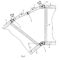
- tabs 1 and 2 are set between. These tabs consist in the illustrated embodiment, each of two-armed levers, wherein one arm is shorter than the other arm.
- the two tabs are each bolted at one end to the upper straps 3 and 4 - at 7.
Landscapes
- Engineering & Computer Science (AREA)
- Mechanical Engineering (AREA)
- Jib Cranes (AREA)
- Farming Of Fish And Shellfish (AREA)
- Tents Or Canopies (AREA)
Description
- Die Erfindung betrifft ein Element zum Verbinden eines Gittersystems mit einem Teleskopauslegerkopf, wobei das Gittersystem aus Obergurten und Untergurten besteht, zwischen denen Streben und/oder Pfosten angeordnet sind.
- Die Erfindung ist nicht beschränkt auf diese Verbindung eines Gittersystems mit einem Teleskopauslegerkopf, sondern kann auch zum Verbinden eines Gittersystems mit einem anderen Gittersystem oder mit einem Adapter zu einem Gittersystem verwendet werden.
- Es ist aus der Praxis allgemein bekannt, dass die Gurte von derartigen Gittersystemen an Verbindungsstellen zwischen dem Teleskopauslegerkopf und den Obergurten und den Untergurten direkt durch Bolzen verbunden sein können oder durch eingefügte Laschen.
- Dabei ist es auch bekannt, dass die Verbindungen zu einer Abwinkelung benutzt werden können, indem die Obergurte und die Untergurte mit dem Teleskopauslegerkopf über unterschiedlich lange Elemente verbunden werden. Weitere Vorrichtungen zum Verbinden eines Gittersystems mit einem Teleskopauslegerkopf sind beispielsweise aus der
DE 36 42 248 A1 und aus derEP 1 477 451 A1 bekannt. - Die Erfindung geht dabei von der Möglichkeit aus, dass der Untergurt eines Gittersystems direkt mit dem Teleskopauslegerkopf verbolzt ist, während der entsprechende Obergurt durch Einfügen einer Lasche so mit dem Teleskopauslegerkopf verbunden ist, dass eine Abwinkelung der auch als Hauptauslegerverlängerung bekannten Gitterteile entsteht.
- Aufgabe der Erfindung ist es eine Möglichkeit zu schaffen, mit der eine einfache Herstellung der Verbindung erfolgen kann, die unter Einhandbedienung oder mechanischer Zuhilfenahme einer einfachen Vorrichtung erfolgen kann, wobei aber insbesondere mehrere Abwinkelungsmöglichkeiten bestehen.
- Gelöst wird diese Aufgabe erfindungsgemäß mit einem Element zum Verbinden der Gurte eines Gittersystems mit einem Teleskopauslegerkopf, wobei das Gittersystem aus Obergurten und Untergurten besteht, zwischen denen Streben und/oder Pfosten angeordnet sind, wobei die Untergurte über eine Verbolzung direkt mit dem Teleskopauslegerkopf verbunden sind, während die Obergurte durch ein Verbindungselement unterschiedlicher Länge derart mit dem Teleskopauslegerkopf verbindbar sind, dass - bezogen auf die Verbindung der Untergurte - die Obergurte unter einem variablen Winkel gegenüber dem Teleskopsauslegerkopf eingestellt werden können, und wobei das Verbindungselement aus zwei an den Obergurten befestigbaren Laschen besteht, die miteinander an unterschiedlichen Punkten verbindbar sind. Dabei ist jede Lasche als mehrarmiger Hebel ausgebildet, wobei die Arme einen Winkel < 90° einschließen und im Bereich des Zusammentreffens der Arme eine Bohrung vorgesehen ist, für die Befestigung der Lasche am Ende des Obergurtes.
- Dabei kann das Verbindungselement aus zwei Laschen bestehen, die gleich ausgebildet aber beim Verbinden spiegelbildlich zueinander angeordnet sind.
- Die Laschen können aber auch unterschiedliche Längen aufweisen.
- Möglich ist auch, dass der eine Arm ein mehrfaches der Länge des anderen Armes aufweist und dass am kürzeren Arm eine und am längeren Arm eine etwa mittige und eine am Ende angeordnete Bohrung zur Verbindung der Laschen miteinander vorgesehen ist.
- Die Erfindung soll nachfolgend an Ausführungsbeispielen erläutert werden. Dabei zeigt
- Fig. 1
- schematisch die Verbindung eines Gittersystems mit einem anderen Gittersystem oder Teleskopauslegerkopf mit 20° Abwinkelung und
- Fig. 2
- eine entsprechende Darstellung mit 40° Abwinkelung.
- Im Einzelnen und übereinstimmend in beiden Figuren sind die Teile bezeichnet mit:
- 1
- Lasche
- 2
- Lasche
- 3
- Obergurt Gittersystem
- 4
- Obergurt zweites Gittersystem oder Teleskopauslegerkopf
- 5
- Untergurt Gittersystemen
- 6
- Untergurt zweites Gittersystem oder Teleskopauslegerkopf
- 7
- Verbolzung
- 8
- Pfosten
- Bei den beiden dargestellten Ausführungsbeispielen ist eine direkte Verbindung der Untergurte 5 und 6 vorgesehen, und zwar durch die Verbolzung 7.
- Bei den Obergurten 3 und 4 sind Laschen 1 und 2 zwischen gesetzt. Diese Laschen bestehen im dargestellten Ausführungsbeispiel jeweils aus zweiarmigen Hebeln, wobei der eine Arm kürzer als der andere Arm ist.
- Bei der 20° Ausführung sind die beiden Laschen jeweils mit einem Ende mit den Obergurten 3 und 4 - bei 7 - verbolzt. Die Verbindung der Laschen selbst erfolgt dabei durch einen weiteren Bolzen 7, der durch die mittleren Öffnungen der beiden Laschen geführt ist.
- Um eine größere Abwinkelung von z. B. 40° zu erhalten, werden - gemäß
Figur 2 - die Laschen 1 und 2 an den zweiten Enden mit einander verbolzt.
Claims (4)
- Element zum Verbinden der Gurte eines Gittersystems, das aus Obergurten (3, 4) und Untergurten (5, 6) besteht, zwischen denen Streben und/oder Pfosten (8) angeordnet sind mit einem Teleskopauslegerkopf, wobei die Untergurte (5, 6) über eine Verbolzung (7) direkt mit dem Teleskopauslegerkopf verbunden sind, während die Obergurte (3, 4) durch ein Verbindungselement unterschiedlicher Länge mit dem Teleskopauslegerkopf derart verbindbar sind, dass - bezogen auf die Verbindung der Untergurte - die Obergurte unter einem variablen Winkel miteinander verbindbar sind, und wobei das Verbindungselement aus zwei jeweils an einem Ende der einander zugewandten Enden der Obergurte befestigbaren Laschen (1, 2) besteht, die mit einander an unterschiedlichen Punkten verbindbar sind,
dadurch gekennzeichnet, dass jede Lasche (1, 2) als zweiarmiger Hebel ausgebildet ist, wobei die Arme einen Winkel < 90° einschließen und im Bereich des Zusammentreffens der Arme eine Bohrung vorgesehen ist für die Befestigung der Lasche am Ende des Obergurtes. - Element nach Anspruch 1, dadurch gekennzeichnet, dass das Verbindungselement aus zwei Laschen (1, 2) besteht, die gleich ausgebildet aber spiegelbildlich zueinander angeordnet sind.
- Element nach einem der vorstehenden Ansprüche, dadurch gekennzeichnet, dass der eine Arm ein mehrfaches der Länge des anderen Armes aufweist und dass am kürzeren Arm eine und am längeren Arm eine etwa mittige und eine am Ende angeordnete Bohrung zur Verbindung der Laschen (1, 2) miteinander vorgesehen ist.
- Element nach einem der vorstehenden Ansprüche, dadurch gekennzeichnet, dass die Laschen (1, 2) unterschiedliche Längen aufweisen.
Applications Claiming Priority (2)
| Application Number | Priority Date | Filing Date | Title |
|---|---|---|---|
| DE202007012204U DE202007012204U1 (de) | 2007-08-29 | 2007-08-29 | Element zum Verbinden eines Gittersystems |
| PCT/DE2008/001173 WO2009026870A1 (de) | 2007-08-29 | 2008-07-16 | Element zum verbinden eines gittersystems |
Publications (2)
| Publication Number | Publication Date |
|---|---|
| EP2183180A1 EP2183180A1 (de) | 2010-05-12 |
| EP2183180B1 true EP2183180B1 (de) | 2013-04-03 |
Family
ID=38650981
Family Applications (1)
| Application Number | Title | Priority Date | Filing Date |
|---|---|---|---|
| EP08784354A Active EP2183180B1 (de) | 2007-08-29 | 2008-07-16 | Element zum verbinden eines gittersystems |
Country Status (5)
| Country | Link |
|---|---|
| US (1) | US8414214B2 (de) |
| EP (1) | EP2183180B1 (de) |
| CN (1) | CN101795956B (de) |
| DE (1) | DE202007012204U1 (de) |
| WO (1) | WO2009026870A1 (de) |
Families Citing this family (12)
| Publication number | Priority date | Publication date | Assignee | Title |
|---|---|---|---|---|
| US9441423B2 (en) * | 2008-02-29 | 2016-09-13 | National Oilwell Varco, L.P. | Drilling rig masts and methods of assembly and erection |
| DE102009022262A1 (de) * | 2009-05-22 | 2010-11-25 | Terex Demag Gmbh | Winkelverstellung eines Auslegersystems |
| US8850774B2 (en) | 2009-12-15 | 2014-10-07 | Production Resource Group Llc | Truss hinge for a stage truss |
| US8915041B2 (en) * | 2011-04-30 | 2014-12-23 | Production Resource Group Llc | Angle spreader for trusses |
| US9091125B2 (en) | 2012-01-16 | 2015-07-28 | National Oilwell Varco, L.P. | Collapsible substructure for a mobile drilling rig |
| CN102602822B (zh) * | 2012-03-26 | 2014-05-21 | 三一汽车起重机械有限公司 | 起重机超起连接支架和起重机 |
| AU2013101084B4 (en) * | 2013-02-11 | 2015-02-05 | 4 Ken Pty Ltd | Method and system for oblique scaffold connection |
| DE102015119381B3 (de) * | 2015-11-10 | 2017-04-27 | Terex Global Gmbh | Mobilkran und Verfahren zum Abwinkeln einer Hauptauslegerverlängerung relativ zu einem Hauptausleger eines Mobilkrans |
| DE102015119379B3 (de) * | 2015-11-10 | 2017-03-30 | Terex Global Gmbh | Mobilkran und Verfahren zum Abwinkeln einer Hauptauslegerverlängerung relativ zu einem Hauptausleger eines Mobilkrans |
| DE102015120350B3 (de) * | 2015-11-24 | 2017-05-24 | Terex Global Gmbh | Mobilkran zum Abwinkeln einer Hauptauslegerverlängerung relativ zu einem Hauptausleger eines Mobilkrans |
| US11192631B2 (en) * | 2018-06-19 | 2021-12-07 | Airbus Operations Gmbh | Connection assembly for transmitting loads between two wing elements |
| US11991959B2 (en) * | 2019-09-27 | 2024-05-28 | Komatsu America Corp. | Work implement, work vehicle and method |
Family Cites Families (10)
| Publication number | Priority date | Publication date | Assignee | Title |
|---|---|---|---|---|
| US2649210A (en) * | 1949-08-09 | 1953-08-18 | Marchese Anthony | Folding boom crane combination |
| US2975910A (en) * | 1958-06-06 | 1961-03-21 | Clark Equipment Co | Crane boom |
| US3085695A (en) * | 1961-03-23 | 1963-04-16 | Carl A Miller | Hinge for crane boom |
| FR2258496B1 (de) * | 1974-01-21 | 1976-06-25 | Poclain Sa | |
| GB1507029A (en) * | 1974-07-19 | 1978-04-12 | Kwikform Ltd | Scaffolding constructions |
| US4484686A (en) * | 1982-04-23 | 1984-11-27 | Kidde, Inc. | Multiple offset boom extension |
| US4653655A (en) | 1985-12-23 | 1987-03-31 | Harnischfeger Corporation | Crane boom having variable angle offset capability |
| WO2002063111A1 (en) * | 2001-02-07 | 2002-08-15 | Charles Hoberman | Loop assemblies having a central link |
| DE10321493B4 (de) * | 2003-05-13 | 2006-07-20 | Grove U.S. Llc | Klappspitzen-Abwinklungsvorrichtung |
| CN2668686Y (zh) * | 2003-11-25 | 2005-01-05 | 上海市机械施工公司 | 内置式无动力液压可调锁紧支承座 |
-
2007
- 2007-08-29 DE DE202007012204U patent/DE202007012204U1/de not_active Expired - Lifetime
-
2008
- 2008-07-16 WO PCT/DE2008/001173 patent/WO2009026870A1/de not_active Ceased
- 2008-07-16 US US12/675,935 patent/US8414214B2/en active Active
- 2008-07-16 CN CN2008801049747A patent/CN101795956B/zh not_active Expired - Fee Related
- 2008-07-16 EP EP08784354A patent/EP2183180B1/de active Active
Also Published As
| Publication number | Publication date |
|---|---|
| WO2009026870A1 (de) | 2009-03-05 |
| CN101795956A (zh) | 2010-08-04 |
| US20100329773A1 (en) | 2010-12-30 |
| US8414214B2 (en) | 2013-04-09 |
| DE202007012204U1 (de) | 2007-10-31 |
| EP2183180A1 (de) | 2010-05-12 |
| CN101795956B (zh) | 2012-10-10 |
Similar Documents
| Publication | Publication Date | Title |
|---|---|---|
| WO2009026870A1 (de) | Element zum verbinden eines gittersystems | |
| EP2019943B1 (de) | Vorrichtung zum verbinden zweier mit flanschen versehener rohr- oder schlauchenden | |
| EP2253576B1 (de) | Winkelverstellung eines Auslegersystems | |
| DE102010039135A1 (de) | Vorrichtung zur Halterung von Systemen sowie Luft- oder Raumfahrzeug | |
| DE102015103209A1 (de) | Fachwerkrahmen, modularer Fachwerkträger und Überbrückungs- und/oder Tragkonstruktion | |
| EP2199247B1 (de) | Drehverbindung | |
| CH656438A5 (de) | Einrichtung zur bildung eines geruests. | |
| WO2018099837A1 (de) | Gerüstelement, gerüst mit einem solchen gerüstelement und verfahren zur montage des gerüsts | |
| DE2703344A1 (de) | Rohrschelle | |
| DE102016123232A1 (de) | Handlauf für Gerüstbauwerke | |
| EP2532982B1 (de) | Vorrichtung zur Sicherung eines mittels Aufhängelaschen in einer mit Aufnahmeschlitz versehenen Konsole gehaltenen Heizkörpers | |
| WO2017005365A1 (de) | Turmkran | |
| EP2046205A1 (de) | Medizinische vorrichtung | |
| DE102018003413A1 (de) | Sportbarren | |
| EP3768918B1 (de) | Betonpumpe mit endschlauchhalter und verfahren zur montage eines endschlauchhalters | |
| DE2145021C3 (de) | Dachbindereinheit für Winterbauhallen | |
| EP1728756B1 (de) | Ausleger | |
| EP2527685A2 (de) | Kettenglied für eine Energieführungskette | |
| DE102019114913A1 (de) | Montageadapter, Sicherheitsgeländer, Bausatz für ein Baugerüst sowie Baugerüst und Verfahren hierfür | |
| DE102010008153A1 (de) | Bolzensicherung an Turmelementen eines Turmkrans | |
| DE102023113611A1 (de) | Geländerholm für ein Gerüst und Verfahren zum Errichten eines Gerüstes | |
| DE102009047149A1 (de) | Anschlusselement und teleskopierbares Vertikalrohr mit demselben | |
| DE102008031242A1 (de) | Anbindungseinrichtung, insbesondere Knotenblech, für ein Gerüstsystem | |
| EP0582119B1 (de) | Lötösenplatte für Lautsprecher | |
| DE3045520A1 (de) | Zweiteilige leitungsschelle und leitungswagen fuer rundleitungen oder schlaeuche mit mehreren zweiteiligen schellen |
Legal Events
| Date | Code | Title | Description |
|---|---|---|---|
| PUAI | Public reference made under article 153(3) epc to a published international application that has entered the european phase |
Free format text: ORIGINAL CODE: 0009012 |
|
| 17P | Request for examination filed |
Effective date: 20100219 |
|
| AK | Designated contracting states |
Kind code of ref document: A1 Designated state(s): AT BE BG CH CY CZ DE DK EE ES FI FR GB GR HR HU IE IS IT LI LT LU LV MC MT NL NO PL PT RO SE SI SK TR |
|
| AX | Request for extension of the european patent |
Extension state: AL BA MK RS |
|
| DAX | Request for extension of the european patent (deleted) | ||
| 17Q | First examination report despatched |
Effective date: 20110317 |
|
| GRAP | Despatch of communication of intention to grant a patent |
Free format text: ORIGINAL CODE: EPIDOSNIGR1 |
|
| RAP1 | Party data changed (applicant data changed or rights of an application transferred) |
Owner name: TEREX CRANES GERMANY GMBH |
|
| GRAS | Grant fee paid |
Free format text: ORIGINAL CODE: EPIDOSNIGR3 |
|
| GRAA | (expected) grant |
Free format text: ORIGINAL CODE: 0009210 |
|
| AK | Designated contracting states |
Kind code of ref document: B1 Designated state(s): AT BE BG CH CY CZ DE DK EE ES FI FR GB GR HR HU IE IS IT LI LT LU LV MC MT NL NO PL PT RO SE SI SK TR |
|
| REG | Reference to a national code |
Ref country code: GB Ref legal event code: FG4D Free format text: NOT ENGLISH |
|
| REG | Reference to a national code |
Ref country code: AT Ref legal event code: REF Ref document number: 604610 Country of ref document: AT Kind code of ref document: T Effective date: 20130415 Ref country code: CH Ref legal event code: EP |
|
| REG | Reference to a national code |
Ref country code: IE Ref legal event code: FG4D Free format text: LANGUAGE OF EP DOCUMENT: GERMAN |
|
| REG | Reference to a national code |
Ref country code: DE Ref legal event code: R096 Ref document number: 502008009630 Country of ref document: DE Effective date: 20130529 |
|
| PG25 | Lapsed in a contracting state [announced via postgrant information from national office to epo] |
Ref country code: SI Free format text: LAPSE BECAUSE OF FAILURE TO SUBMIT A TRANSLATION OF THE DESCRIPTION OR TO PAY THE FEE WITHIN THE PRESCRIBED TIME-LIMIT Effective date: 20130403 |
|
| REG | Reference to a national code |
Ref country code: NL Ref legal event code: VDEP Effective date: 20130403 |
|
| REG | Reference to a national code |
Ref country code: LT Ref legal event code: MG4D |
|
| PG25 | Lapsed in a contracting state [announced via postgrant information from national office to epo] |
Ref country code: SE Free format text: LAPSE BECAUSE OF FAILURE TO SUBMIT A TRANSLATION OF THE DESCRIPTION OR TO PAY THE FEE WITHIN THE PRESCRIBED TIME-LIMIT Effective date: 20130403 Ref country code: NL Free format text: LAPSE BECAUSE OF FAILURE TO SUBMIT A TRANSLATION OF THE DESCRIPTION OR TO PAY THE FEE WITHIN THE PRESCRIBED TIME-LIMIT Effective date: 20130403 Ref country code: LT Free format text: LAPSE BECAUSE OF FAILURE TO SUBMIT A TRANSLATION OF THE DESCRIPTION OR TO PAY THE FEE WITHIN THE PRESCRIBED TIME-LIMIT Effective date: 20130403 Ref country code: IS Free format text: LAPSE BECAUSE OF FAILURE TO SUBMIT A TRANSLATION OF THE DESCRIPTION OR TO PAY THE FEE WITHIN THE PRESCRIBED TIME-LIMIT Effective date: 20130803 Ref country code: ES Free format text: LAPSE BECAUSE OF FAILURE TO SUBMIT A TRANSLATION OF THE DESCRIPTION OR TO PAY THE FEE WITHIN THE PRESCRIBED TIME-LIMIT Effective date: 20130714 Ref country code: FI Free format text: LAPSE BECAUSE OF FAILURE TO SUBMIT A TRANSLATION OF THE DESCRIPTION OR TO PAY THE FEE WITHIN THE PRESCRIBED TIME-LIMIT Effective date: 20130403 Ref country code: GR Free format text: LAPSE BECAUSE OF FAILURE TO SUBMIT A TRANSLATION OF THE DESCRIPTION OR TO PAY THE FEE WITHIN THE PRESCRIBED TIME-LIMIT Effective date: 20130704 Ref country code: NO Free format text: LAPSE BECAUSE OF FAILURE TO SUBMIT A TRANSLATION OF THE DESCRIPTION OR TO PAY THE FEE WITHIN THE PRESCRIBED TIME-LIMIT Effective date: 20130703 Ref country code: PT Free format text: LAPSE BECAUSE OF FAILURE TO SUBMIT A TRANSLATION OF THE DESCRIPTION OR TO PAY THE FEE WITHIN THE PRESCRIBED TIME-LIMIT Effective date: 20130805 |
|
| PGFP | Annual fee paid to national office [announced via postgrant information from national office to epo] |
Ref country code: AT Payment date: 20130711 Year of fee payment: 6 |
|
| PG25 | Lapsed in a contracting state [announced via postgrant information from national office to epo] |
Ref country code: CY Free format text: LAPSE BECAUSE OF FAILURE TO SUBMIT A TRANSLATION OF THE DESCRIPTION OR TO PAY THE FEE WITHIN THE PRESCRIBED TIME-LIMIT Effective date: 20130403 Ref country code: BG Free format text: LAPSE BECAUSE OF FAILURE TO SUBMIT A TRANSLATION OF THE DESCRIPTION OR TO PAY THE FEE WITHIN THE PRESCRIBED TIME-LIMIT Effective date: 20130703 Ref country code: PL Free format text: LAPSE BECAUSE OF FAILURE TO SUBMIT A TRANSLATION OF THE DESCRIPTION OR TO PAY THE FEE WITHIN THE PRESCRIBED TIME-LIMIT Effective date: 20130403 Ref country code: LV Free format text: LAPSE BECAUSE OF FAILURE TO SUBMIT A TRANSLATION OF THE DESCRIPTION OR TO PAY THE FEE WITHIN THE PRESCRIBED TIME-LIMIT Effective date: 20130403 Ref country code: HR Free format text: LAPSE BECAUSE OF FAILURE TO SUBMIT A TRANSLATION OF THE DESCRIPTION OR TO PAY THE FEE WITHIN THE PRESCRIBED TIME-LIMIT Effective date: 20130403 |
|
| PGFP | Annual fee paid to national office [announced via postgrant information from national office to epo] |
Ref country code: GB Payment date: 20130719 Year of fee payment: 6 |
|
| BERE | Be: lapsed |
Owner name: TEREX CRANES GERMANY G.M.B.H. Effective date: 20130731 |
|
| PG25 | Lapsed in a contracting state [announced via postgrant information from national office to epo] |
Ref country code: DK Free format text: LAPSE BECAUSE OF FAILURE TO SUBMIT A TRANSLATION OF THE DESCRIPTION OR TO PAY THE FEE WITHIN THE PRESCRIBED TIME-LIMIT Effective date: 20130403 Ref country code: CZ Free format text: LAPSE BECAUSE OF FAILURE TO SUBMIT A TRANSLATION OF THE DESCRIPTION OR TO PAY THE FEE WITHIN THE PRESCRIBED TIME-LIMIT Effective date: 20130403 Ref country code: SK Free format text: LAPSE BECAUSE OF FAILURE TO SUBMIT A TRANSLATION OF THE DESCRIPTION OR TO PAY THE FEE WITHIN THE PRESCRIBED TIME-LIMIT Effective date: 20130403 Ref country code: EE Free format text: LAPSE BECAUSE OF FAILURE TO SUBMIT A TRANSLATION OF THE DESCRIPTION OR TO PAY THE FEE WITHIN THE PRESCRIBED TIME-LIMIT Effective date: 20130403 |
|
| PLBE | No opposition filed within time limit |
Free format text: ORIGINAL CODE: 0009261 |
|
| STAA | Information on the status of an ep patent application or granted ep patent |
Free format text: STATUS: NO OPPOSITION FILED WITHIN TIME LIMIT |
|
| PG25 | Lapsed in a contracting state [announced via postgrant information from national office to epo] |
Ref country code: MC Free format text: LAPSE BECAUSE OF FAILURE TO SUBMIT A TRANSLATION OF THE DESCRIPTION OR TO PAY THE FEE WITHIN THE PRESCRIBED TIME-LIMIT Effective date: 20130403 Ref country code: RO Free format text: LAPSE BECAUSE OF FAILURE TO SUBMIT A TRANSLATION OF THE DESCRIPTION OR TO PAY THE FEE WITHIN THE PRESCRIBED TIME-LIMIT Effective date: 20130403 Ref country code: IT Free format text: LAPSE BECAUSE OF FAILURE TO SUBMIT A TRANSLATION OF THE DESCRIPTION OR TO PAY THE FEE WITHIN THE PRESCRIBED TIME-LIMIT Effective date: 20130403 |
|
| REG | Reference to a national code |
Ref country code: CH Ref legal event code: PL |
|
| 26N | No opposition filed |
Effective date: 20140106 |
|
| REG | Reference to a national code |
Ref country code: DE Ref legal event code: R097 Ref document number: 502008009630 Country of ref document: DE Effective date: 20140106 |
|
| REG | Reference to a national code |
Ref country code: IE Ref legal event code: MM4A |
|
| PG25 | Lapsed in a contracting state [announced via postgrant information from national office to epo] |
Ref country code: BE Free format text: LAPSE BECAUSE OF NON-PAYMENT OF DUE FEES Effective date: 20130731 Ref country code: CH Free format text: LAPSE BECAUSE OF NON-PAYMENT OF DUE FEES Effective date: 20130731 Ref country code: LI Free format text: LAPSE BECAUSE OF NON-PAYMENT OF DUE FEES Effective date: 20130731 |
|
| PG25 | Lapsed in a contracting state [announced via postgrant information from national office to epo] |
Ref country code: IE Free format text: LAPSE BECAUSE OF NON-PAYMENT OF DUE FEES Effective date: 20130716 |
|
| REG | Reference to a national code |
Ref country code: AT Ref legal event code: MM01 Ref document number: 604610 Country of ref document: AT Kind code of ref document: T Effective date: 20140716 |
|
| GBPC | Gb: european patent ceased through non-payment of renewal fee |
Effective date: 20140716 |
|
| PG25 | Lapsed in a contracting state [announced via postgrant information from national office to epo] |
Ref country code: AT Free format text: LAPSE BECAUSE OF NON-PAYMENT OF DUE FEES Effective date: 20140716 Ref country code: GB Free format text: LAPSE BECAUSE OF NON-PAYMENT OF DUE FEES Effective date: 20140716 |
|
| PG25 | Lapsed in a contracting state [announced via postgrant information from national office to epo] |
Ref country code: MT Free format text: LAPSE BECAUSE OF FAILURE TO SUBMIT A TRANSLATION OF THE DESCRIPTION OR TO PAY THE FEE WITHIN THE PRESCRIBED TIME-LIMIT Effective date: 20130403 |
|
| PG25 | Lapsed in a contracting state [announced via postgrant information from national office to epo] |
Ref country code: LU Free format text: LAPSE BECAUSE OF NON-PAYMENT OF DUE FEES Effective date: 20130716 Ref country code: HU Free format text: LAPSE BECAUSE OF FAILURE TO SUBMIT A TRANSLATION OF THE DESCRIPTION OR TO PAY THE FEE WITHIN THE PRESCRIBED TIME-LIMIT; INVALID AB INITIO Effective date: 20080716 |
|
| REG | Reference to a national code |
Ref country code: DE Ref legal event code: R082 Ref document number: 502008009630 Country of ref document: DE Representative=s name: MOSER GOETZE & PARTNER PATENTANWAELTE MBB, DE Ref country code: DE Ref legal event code: R082 Ref document number: 502008009630 Country of ref document: DE Representative=s name: RAU, SCHNECK & HUEBNER PATENTANWAELTE RECHTSAN, DE Ref country code: DE Ref legal event code: R081 Ref document number: 502008009630 Country of ref document: DE Owner name: TEREX GLOBAL GMBH, CH Free format text: FORMER OWNER: TEREX CRANES GERMANY GMBH, 66482 ZWEIBRUECKEN, DE |
|
| REG | Reference to a national code |
Ref country code: FR Ref legal event code: PLFP Year of fee payment: 9 |
|
| REG | Reference to a national code |
Ref country code: FR Ref legal event code: TP Owner name: TEREX GLOBAL GMBH, CH Effective date: 20161124 |
|
| REG | Reference to a national code |
Ref country code: DE Ref legal event code: R082 Ref document number: 502008009630 Country of ref document: DE Representative=s name: MOSER GOETZE & PARTNER PATENTANWAELTE MBB, DE |
|
| REG | Reference to a national code |
Ref country code: FR Ref legal event code: PLFP Year of fee payment: 10 |
|
| REG | Reference to a national code |
Ref country code: FR Ref legal event code: PLFP Year of fee payment: 11 |
|
| PGFP | Annual fee paid to national office [announced via postgrant information from national office to epo] |
Ref country code: TR Payment date: 20200716 Year of fee payment: 13 Ref country code: FR Payment date: 20200723 Year of fee payment: 13 |
|
| PG25 | Lapsed in a contracting state [announced via postgrant information from national office to epo] |
Ref country code: FR Free format text: LAPSE BECAUSE OF NON-PAYMENT OF DUE FEES Effective date: 20210731 |
|
| P01 | Opt-out of the competence of the unified patent court (upc) registered |
Effective date: 20230530 |
|
| PG25 | Lapsed in a contracting state [announced via postgrant information from national office to epo] |
Ref country code: TR Free format text: LAPSE BECAUSE OF NON-PAYMENT OF DUE FEES Effective date: 20210716 |
|
| PGFP | Annual fee paid to national office [announced via postgrant information from national office to epo] |
Ref country code: DE Payment date: 20250722 Year of fee payment: 18 |