EP2181898A1 - Fahrunterstützungssystem und damit verbundene fahrzeuge - Google Patents
Fahrunterstützungssystem und damit verbundene fahrzeuge Download PDFInfo
- Publication number
- EP2181898A1 EP2181898A1 EP08829242A EP08829242A EP2181898A1 EP 2181898 A1 EP2181898 A1 EP 2181898A1 EP 08829242 A EP08829242 A EP 08829242A EP 08829242 A EP08829242 A EP 08829242A EP 2181898 A1 EP2181898 A1 EP 2181898A1
- Authority
- EP
- European Patent Office
- Prior art keywords
- vehicle
- bird
- image
- eye view
- movement
- Prior art date
- Legal status (The legal status is an assumption and is not a legal conclusion. Google has not performed a legal analysis and makes no representation as to the accuracy of the status listed.)
- Withdrawn
Links
- 240000004050 Pentaglottis sempervirens Species 0.000 claims abstract description 143
- 235000004522 Pentaglottis sempervirens Nutrition 0.000 claims abstract description 143
- 230000003287 optical effect Effects 0.000 claims abstract description 45
- 230000008878 coupling Effects 0.000 claims description 104
- 238000010168 coupling process Methods 0.000 claims description 104
- 238000005859 coupling reaction Methods 0.000 claims description 104
- 239000013598 vector Substances 0.000 claims description 69
- 230000001131 transforming effect Effects 0.000 claims description 11
- 238000012545 processing Methods 0.000 description 41
- 230000009466 transformation Effects 0.000 description 25
- 238000010586 diagram Methods 0.000 description 19
- 238000000034 method Methods 0.000 description 18
- 238000012937 correction Methods 0.000 description 4
- 238000006073 displacement reaction Methods 0.000 description 4
- 230000006870 function Effects 0.000 description 4
- 239000011159 matrix material Substances 0.000 description 4
- 230000008901 benefit Effects 0.000 description 3
- 238000009795 derivation Methods 0.000 description 3
- 238000005516 engineering process Methods 0.000 description 3
- 230000012447 hatching Effects 0.000 description 2
- 229910000831 Steel Inorganic materials 0.000 description 1
- 238000004364 calculation method Methods 0.000 description 1
- 230000000295 complement effect Effects 0.000 description 1
- 230000001747 exhibiting effect Effects 0.000 description 1
- 239000004973 liquid crystal related substance Substances 0.000 description 1
- 238000013507 mapping Methods 0.000 description 1
- 229910044991 metal oxide Inorganic materials 0.000 description 1
- 150000004706 metal oxides Chemical class 0.000 description 1
- 238000012986 modification Methods 0.000 description 1
- 230000004048 modification Effects 0.000 description 1
- 239000004065 semiconductor Substances 0.000 description 1
- 239000007787 solid Substances 0.000 description 1
- 238000002187 spin decoupling employing ultra-broadband-inversion sequences generated via simulated annealing Methods 0.000 description 1
- 239000010959 steel Substances 0.000 description 1
- 238000012360 testing method Methods 0.000 description 1
Images


Classifications
-
- B—PERFORMING OPERATIONS; TRANSPORTING
- B62—LAND VEHICLES FOR TRAVELLING OTHERWISE THAN ON RAILS
- B62D—MOTOR VEHICLES; TRAILERS
- B62D13/00—Steering specially adapted for trailers
- B62D13/06—Steering specially adapted for trailers for backing a normally drawn trailer
-
- B—PERFORMING OPERATIONS; TRANSPORTING
- B60—VEHICLES IN GENERAL
- B60R—VEHICLES, VEHICLE FITTINGS, OR VEHICLE PARTS, NOT OTHERWISE PROVIDED FOR
- B60R1/00—Optical viewing arrangements; Real-time viewing arrangements for drivers or passengers using optical image capturing systems, e.g. cameras or video systems specially adapted for use in or on vehicles
- B60R1/20—Real-time viewing arrangements for drivers or passengers using optical image capturing systems, e.g. cameras or video systems specially adapted for use in or on vehicles
- B60R1/22—Real-time viewing arrangements for drivers or passengers using optical image capturing systems, e.g. cameras or video systems specially adapted for use in or on vehicles for viewing an area outside the vehicle, e.g. the exterior of the vehicle
- B60R1/23—Real-time viewing arrangements for drivers or passengers using optical image capturing systems, e.g. cameras or video systems specially adapted for use in or on vehicles for viewing an area outside the vehicle, e.g. the exterior of the vehicle with a predetermined field of view
- B60R1/26—Real-time viewing arrangements for drivers or passengers using optical image capturing systems, e.g. cameras or video systems specially adapted for use in or on vehicles for viewing an area outside the vehicle, e.g. the exterior of the vehicle with a predetermined field of view to the rear of the vehicle
-
- B—PERFORMING OPERATIONS; TRANSPORTING
- B62—LAND VEHICLES FOR TRAVELLING OTHERWISE THAN ON RAILS
- B62D—MOTOR VEHICLES; TRAILERS
- B62D15/00—Steering not otherwise provided for
- B62D15/02—Steering position indicators ; Steering position determination; Steering aids
- B62D15/027—Parking aids, e.g. instruction means
- B62D15/0275—Parking aids, e.g. instruction means by overlaying a vehicle path based on present steering angle over an image without processing that image
-
- G—PHYSICS
- G06—COMPUTING; CALCULATING OR COUNTING
- G06T—IMAGE DATA PROCESSING OR GENERATION, IN GENERAL
- G06T7/00—Image analysis
- G06T7/20—Analysis of motion
- G06T7/246—Analysis of motion using feature-based methods, e.g. the tracking of corners or segments
-
- H—ELECTRICITY
- H04—ELECTRIC COMMUNICATION TECHNIQUE
- H04N—PICTORIAL COMMUNICATION, e.g. TELEVISION
- H04N7/00—Television systems
- H04N7/18—Closed-circuit television [CCTV] systems, i.e. systems in which the video signal is not broadcast
- H04N7/183—Closed-circuit television [CCTV] systems, i.e. systems in which the video signal is not broadcast for receiving images from a single remote source
-
- B—PERFORMING OPERATIONS; TRANSPORTING
- B60—VEHICLES IN GENERAL
- B60R—VEHICLES, VEHICLE FITTINGS, OR VEHICLE PARTS, NOT OTHERWISE PROVIDED FOR
- B60R2300/00—Details of viewing arrangements using cameras and displays, specially adapted for use in a vehicle
- B60R2300/60—Details of viewing arrangements using cameras and displays, specially adapted for use in a vehicle characterised by monitoring and displaying vehicle exterior scenes from a transformed perspective
- B60R2300/607—Details of viewing arrangements using cameras and displays, specially adapted for use in a vehicle characterised by monitoring and displaying vehicle exterior scenes from a transformed perspective from a bird's eye viewpoint
-
- B—PERFORMING OPERATIONS; TRANSPORTING
- B60—VEHICLES IN GENERAL
- B60R—VEHICLES, VEHICLE FITTINGS, OR VEHICLE PARTS, NOT OTHERWISE PROVIDED FOR
- B60R2300/00—Details of viewing arrangements using cameras and displays, specially adapted for use in a vehicle
- B60R2300/80—Details of viewing arrangements using cameras and displays, specially adapted for use in a vehicle characterised by the intended use of the viewing arrangement
- B60R2300/806—Details of viewing arrangements using cameras and displays, specially adapted for use in a vehicle characterised by the intended use of the viewing arrangement for aiding parking
-
- B—PERFORMING OPERATIONS; TRANSPORTING
- B60—VEHICLES IN GENERAL
- B60R—VEHICLES, VEHICLE FITTINGS, OR VEHICLE PARTS, NOT OTHERWISE PROVIDED FOR
- B60R2300/00—Details of viewing arrangements using cameras and displays, specially adapted for use in a vehicle
- B60R2300/80—Details of viewing arrangements using cameras and displays, specially adapted for use in a vehicle characterised by the intended use of the viewing arrangement
- B60R2300/8086—Details of viewing arrangements using cameras and displays, specially adapted for use in a vehicle characterised by the intended use of the viewing arrangement for vehicle path indication
-
- G—PHYSICS
- G06—COMPUTING; CALCULATING OR COUNTING
- G06T—IMAGE DATA PROCESSING OR GENERATION, IN GENERAL
- G06T2207/00—Indexing scheme for image analysis or image enhancement
- G06T2207/10—Image acquisition modality
- G06T2207/10016—Video; Image sequence
-
- G—PHYSICS
- G06—COMPUTING; CALCULATING OR COUNTING
- G06T—IMAGE DATA PROCESSING OR GENERATION, IN GENERAL
- G06T2207/00—Indexing scheme for image analysis or image enhancement
- G06T2207/30—Subject of image; Context of image processing
- G06T2207/30241—Trajectory
-
- G—PHYSICS
- G06—COMPUTING; CALCULATING OR COUNTING
- G06T—IMAGE DATA PROCESSING OR GENERATION, IN GENERAL
- G06T2207/00—Indexing scheme for image analysis or image enhancement
- G06T2207/30—Subject of image; Context of image processing
- G06T2207/30248—Vehicle exterior or interior
- G06T2207/30252—Vehicle exterior; Vicinity of vehicle
- G06T2207/30264—Parking
Definitions
- the present invention relates to a driving assistance system for assisting the driving of an articulated vehicle (coupled, or connected vehicles), and also relates to an articulated vehicle employing such a driving assistance system.
- articulated vehicles composed of a tractor and a trailer towed by the tractor, are comparatively difficult to drive, and thus they benefit well from driving assistance using a camera.
- the trailer can swivel about a coupling as a pivot, and this makes it difficult for the driver to recognize how the rear end of the trailer moves as the tractor moves.
- Patent Document 1 listed below discloses a technology according to which, with a camera installed at the rear of a towing vehicle and another at the rear of a towed vehicle, the predicted movement course of the towed vehicle is determined and displayed in a form superimposed on an image behind the towed vehicle.
- this technology absolutely requires two cameras, leading to an expensive system as a whole.
- Patent Document 1 JP-2006-256544
- a first driving assistance system which includes a camera provided, in an articulated vehicle composed of a first vehicle and a second vehicle coupled to the first vehicle, on the second vehicle to shoot behind the second vehicle, and which acquires a plurality of chronologically ordered shot images from the camera and outputs a display image generated from the shot images to a display device, is characterized by the provision of: a motion detecting portion which derives an optical flow of the moving image formed by the plurality of shot images; a coupling angle estimating portion which estimates the coupling angle of the first and second vehicles based on the optical flow and on movement information of the first vehicle fed to the coupling angle estimating portion; and a movement course estimating portion which derives a predicted movement course of the second vehicle based on the coupling angle and on the movement information of the first vehicle.
- the display image is generated by superimposing a sign based on the predicted movement course on an image based on the shot images.
- the first driving assistance system is further characterized by the provision of: a coordinate transforming portion which transforms the plurality of shot images to a plurality of bird's-eye view images by projecting the shot images onto a predetermined bird's-eye view coordinate system.
- the optical flow derived by the motion detecting portion is an optical flow on the bird's-eye view coordinate system.
- the first driving assistance system is further characterized in that the movement information of the first vehicle includes information representing the movement direction and movement speed of the first vehicle, and that the coupling angle estimating portion derives a vector representing the movement direction and movement amount of the first vehicle on the bird's-eye view coordinate system based on the movement information of the first vehicle, and estimates the coupling angle based on the vector and on the optical flow.
- the first driving assistance system is further characterized by the provision of: an indicating portion which gives, to outside, an indication according to the result of comparison of the estimated coupling angle with a predetermined threshold angle.
- a second driving assistance system which includes a camera provided, in an articulated vehicle composed of a first vehicle and a second vehicle coupled to the first vehicle, on the second vehicle to shoot behind the second vehicle, and which acquires a plurality of chronologically ordered shot images from the camera and outputs a display image generated from the shot images to a display device, is characterized by the provision of: a motion detecting portion which derives an optical flow of the moving image formed by the plurality of shot images; and a movement direction estimating portion which estimates the movement direction of the second vehicle based on the optical flow.
- the result of estimation by the movement direction estimating portion is reflected in the display image.
- the second driving assistance system is further characterized by the provision of: a coordinate transforming portion which transforms the plurality of shot images to a plurality of bird's-eye view images by projecting the shot images onto a predetermined bird's-eye view coordinate system.
- the optical flow derived by the motion detecting portion is an optical flow on the bird's-eye view coordinate system.
- the second driving assistance system is further characterized by the provision of: a coupling angle estimating portion which estimates a coupling angle of the first and second vehicles based on the optical flow and on movement information of the first vehicle fed to the coupling angle estimating portion.
- a coupling angle estimating portion which estimates a coupling angle of the first and second vehicles based on the optical flow and on movement information of the first vehicle fed to the coupling angle estimating portion.
- the second driving assistance system is further characterized in that the movement information of the first vehicle includes information representing the movement direction and movement speed of the first vehicle, and that the coupling angle estimating portion derives a vector representing the movement direction and movement amount of the first vehicle on the bird's-eye view coordinate system based on the movement information of the first vehicle, and estimates the coupling angle based on the vector and on the optical flow.
- the second driving assistance system is further characterized by the provision of: an indicating portion which gives, to outside, an indication according to the result of comparison of the estimated coupling angle with a predetermined threshold angle.
- an articulated vehicle according to the invention is characterized by being composed of a first vehicle and a second vehicle coupled to the first vehicle, and being provided with any of the driving assistance systems described above.
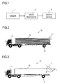
- Fig. 1 is a configuration block diagram of a driving assistance system embodying the invention.
- the driving assistance system in Fig. 1 is provided with a camera 1, an image processor 2, and a display device 3.
- the camera 1 performs shooting, and outputs a signal representing the image obtained by the shooting to the image processor 2.
- the image processor 2 generates from the image obtained from the camera 1 a display image.
- the image processor 2 outputs a video signal representing the generated display image to the display device 3, and according to the video signal fed to it, the display device 3 displays the display image as video.
- the image as it is obtained by the shooting by the camera 1 is often subject to lens distortion. Accordingly, the image processor 2 applies lens distortion correction to the image as it is obtained by the shooting by the camera 1, and generates the display image based on the image after lens distortion correction.
- the image after lens distortion correction is called the shot image.
- the image as it is obtained by the shooting by the camera 1 is itself the shot image.
- the shot image may be read as the camera image.
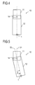
- Fig. 2 is an exterior side view of an articulated vehicle 10 on which the driving assistance system in Fig. 1 is installed.
- the articulated vehicle 10 is composed of a tractor 11 and a trailer 12 coupled to and towed by the tractor 11.
- the reference sign 13 indicates wheels provided on the trailer 12.
- the wheels 13 are ones generally called the rear wheels of the trailer 12.
- the camera 1 is installed at the top end of the rear face of the trailer 12, and shoots the surroundings of the trailer 12.
- the articulated vehicle 10 is placed on a road surface and travels on it.
- the road surface is parallel to the horizontal plane. It is also assumed that what is referred to simply as a "height" is a height relative to the road surface.
- the ground surface is synonymous with the road surface.
- the direction looking from the trailer 12 to the tractor 11 will be referred to as the front direction, and the direction looking from the tractor 11 to the trailer 12 will be referred to as the rear direction.
- the image processor 2 comprises, for example, an integrated circuit.
- the display device 3 comprises a liquid crystal display panel or the like.
- a display device as is incorporated in a car navigation system or the like may be shared as the display device 3 in the driving assistance system.
- the image processor 2 may be incorporated in a car navigation system as part of it.
- the image processor 2 and the display device 3 are installed, for example, near the driver's seat inside the tractor 11.
- Fig. 3 is an exterior side view of the articulated vehicle 10.
- the camera 1 is illustrated in exaggerated size, and the trailer 12 with a different pattern than in Fig. 2 .
- the camera 1 is installed so as to point rearward of the trailer 12, obliquely downward, so that the field of view of the camera 1 covers the road surface and any solid object located behind the trailer 12.
- the optical axis of the camera 1 forms two angles, represented by ⁇ and ⁇ 2 , respectively, in Fig. 3 .
- the angle ⁇ 2 is generally called angle of depression, or dip.
- Figs. 4 and 5 are each a plan view of the articulated vehicle 10 as seen from above.
- the tractor 11 and the trailer 12 are each represented by a simple rectangle.
- Fig. 4 is a plan view in a case where the angle formed by the tractor 11 and the trailer 12 (hereinafter referred to as the "coupling angle") is equal to 0°
- Fig. 5 is a plan view in a case where the coupling angle is not equal to 0°.
- the coupling angle is equal to 0°
- the tractor 11 and the trailer 12 align in a straight line (the bodies of the tractor 11 and the trailer 12 align in a straight line).
- the reference sign 14 indicates the coupling (pivot) between the tractor 11 and the trailer 12.
- the trailer 12 is coupled to the tractor 11.
- the trailer 12 swivels relative to the tractor 11.
- the angle formed by the center line 21 through the body of the tractor 11 and the center line 22 through the body of the trailer 12 corresponds to the above-mentioned coupling angle, and this coupling angle is represented by ⁇ CN .
- the center lines 21 and 22 are center lines parallel to the traveling direction of the articulated vehicle 10 when it is traveling straight ahead.
- a coupling angle ⁇ CN that occurs when, with the tractor 11 and the trailer 12 viewed from above, the trailer 12 swivels counter-clockwise about the coupling 14 is defined to be positive. Accordingly, a coupling angle ⁇ CN that occurs when the articulated vehicle 10 having been traveling straight ahead is about to turn right is positive.
- the image processor 2 in Fig. 1 is provided with a function of transforming the shot image to a bird's-eye view image by coordinate transformation.
- the coordinate transformation for generating the bird's-eye view image from the shot image is called "bird's-eye transformation.” A method for such bird's-eye transformation will now be described.
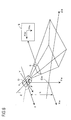
- Fig. 6 shows a relationship among a camera coordinate system XYZ, a coordinate system of the image-sensing plane S of the camera 1 (a camera image-sensing plane S coordinate system) X bu Y bu , and a world coordinate system X w Y w Z w including a two-dimensional ground surface coordinate system X w Z w .
- the coordinate system X bu Y bu is the coordinate system on which the shot image is defined.
- the camera coordinate system XYZ is a three-dimensional coordinate system having X, Y, and Z axes as its coordinate axes.
- the image-sensing plane S coordinate system X bu Y bu is a two-dimensional coordinate system having X bu and Y bu axes.
- the two-dimensional ground surface coordinate system X w Z w is a two-dimensional coordinate system having X w and Z w axes.
- the world coordinate system X w Y w Z w is a three-dimensional coordinate system having X w , Y w , and Z w axes as its coordinate axes.
- the camera coordinate system XYZ, the image-sensing plane S coordinate system X bu Y bu , the two-dimensional ground surface coordinate system X w Z w , and the world coordinate system X w Y w Z w are sometimes abbreviated to the camera coordinate system, the image-sensing plane S coordinate system, the two-dimensional ground surface coordinate system, and the world coordinate system respectively.
- the optical center of the camera 1 is taken as origin O
- Z axis is aligned with the optical axis
- X axis is defined to be perpendicular to Z axis and parallel to the ground surface
- Y axis is defined to be perpendicular to both Z and X axes.
- the center of the image-sensing plane S is taken as the origin
- X bu axis is aligned with the lateral (width) direction of the image-sensing plane S
- Y bu axis is aligned with the longitudinal (height) direction of the image-sensing plane S.
- Y w axis is defined to be perpendicular to the ground surface
- X w axis is defined to be parallel to X axis of the camera coordinate system XYZ
- Z w axis is defined to be perpendicular to both X w and Y w directions.
- the amount of translational displacement between X w axis and X axis equals h, and the direction of this translational displacement is the plumb line direction.
- the obtuse angle formed by Z w axis and Z axis is equal to the inclination angle ⁇ .
- the values of h and ⁇ are previously set and fed to the image processor 2.
- the coordinates (coordinate values) of a pixel in the camera coordinate system XYZ are represented by (x, y, z).
- the symbols x, y, and z represent the X-, Y-, and Z-axis components, respectively, in the camera coordinate system XYZ.
- the coordinates of a pixel in the world coordinate system X w Y w Z w are represented by (x w , y w , z w ).
- the symbols x w , y w , and z w represent the X w -, Y w -, and Z w -axis components, respectively, in the world coordinate system X w Y w Z w .
- the coordinates of a pixel in the two-dimensional ground surface coordinate system X w Z w are represented by (x w , z w ).
- the symbols x w and z w represent the X w - and Z w -axis components, respectively, in the two-dimensional ground surface coordinate system X w Z w , and these are equal to the X w - and Z w -axis components in the world coordinate system X w Y w Z w .
- the coordinates of a pixel in the image-sensing plane S coordinate system X bu Y bu are represented by (x bu , y bu ).
- the symbols x bu and y bu represent the X bu - and Y bu -axis components, respectively, in the image-sensing plane S coordinate system X bu Y bu .
- a transformation formula between coordinates (x, y, z) in the camera coordinate system XYZ and coordinates (x w , y w , z w ) in the world coordinate system X w Y w Z w is given by (1) below.
- Formulae (1) and (2) above give a transformation formula, (3) below, between coordinates (x bu , y bu ) in the image-sensing plane S coordinate system X bu Y bu and coordinates (x w , z W ) in the two-dimensional ground surface coordinate system X w Z w .
- a bird's-eye view coordinate system X au Y au is also defined as a coordinate system for the bird's-eye view image.
- the bird's-eye view coordinate system X au Y au is a two-dimensional coordinate system having X au and Y au axes as its coordinate axes.
- the coordinates of a pixel in the bird's-eye view coordinate system X au Y au are represented by (x au , y au ).
- the bird's-eye view image is represented by the pixel signals of a plurality of pixels in a two-dimensional array, and the position of an individual pixel on the bird's-eye view image is represented by coordinates (x au , y au ).
- the symbols x au and y au represent the X au - and Y au -axis components, respectively, in the bird's-eye view coordinate system X au Y au .
- the bird's-eye view image is obtained by transforming the shot image as actually obtained by the shooting by the camera 1 to an image as seen from the viewpoint of a virtual camera (hereinafter referred to as the virtual viewpoint). More specifically, the bird's-eye view image is obtained by transforming the shot image to an image as seen when looking down to the ground surface in the plumb line direction.
- This kind of image transformation is also generally canted viewpoint transformation
- the plane on which the two-dimensional ground surface coordinate system X w Z w is defined and which coincides with the ground surface is parallel to the plane on which the bird's-eye view coordinate system X au Y au is defined. Accordingly, projection from the two-dimensional ground surface coordinate system X w Z w onto the bird's-eye view coordinate system X au Y au of the virtual camera is achieved by parallel projection.
- the height of the virtual camera that is, the height of the virtual viewpoint
- Formula (6) above gives formula (7) below for transformation from coordinates (x bu , y bu ) in the image-sensing plane S coordinate system X bu Y bu to coordinates (x au , y au ) in the bird's-eye view coordinate system X au Y au .
- the bird's-eye view image is composed of pixels arrayed in the bird's-eye view coordinate system.
- table data is created which indicates the correspondence between the coordinates (x bu , y bu ) of the individual pixels on the shot image and the coordinates (x au , y au ) of the individual pixels on the bird's-eye view image, and the table data is previously stored in an unillustrated memory (lookup table); then, by use of the table data, the shot image is transformed to the bird's-eye view image.
- the bird's-eye view image may instead be generated by performing coordinate transformation calculation based on formula (7) every time the shot image is acquired.
- Example 1 will be described.
- the image processor 2 in Fig. 1 acquires shot images from the camera 1 at predetermined periods, and generates, from the shot images thus sequentially acquired, one display image after another to output the most recent display image to the display device 3.
- the display device 3 displays the most recent display image in a constantly updated fashion.
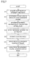
- FIG. 7 is a flow chart showing a flow of such operation.
- the processing at steps S11 through S17 shown in Fig. 7 is executed by image processor 2 in Fig. 1 .
- the image processor 2 acquires a plurality of shot images shot at different time points, and refers to those shot images in later processing (step S11).
- the plurality of shot images thus acquired include a shot image obtained by shooting at time point t1 (hereinafter referred to simply as the shot image at time point t1) and a shot image obtained by shooting at time point t2 (hereinafter referred to simply as the shot image at time point t2).
- time point t1 and time point t2 occur in this order.
- the articulated vehicle 10 moves. Accordingly, the viewpoint of the camera 1 differs between at time point t1 and at time point t2.
- step S12 After the acquisition of the shot images at time points t1 and t2, at step S12, the optical flow between time points t1 and t2 is determined. It should be noted that the optical flow determined at step S12 is one on the bird's-eye view coordinate system.
- step S12 the following processing is performed.
- the shot images at time points t1 and t2 are each transformed to a bird's-eye view image by the bird's-eye transformation described above.
- the bird's-eye view images based on the shot images at time points t1 and t2 are called the bird's-eye view images at time points t1 and t2 respectively.
- the bird's-eye view images at time points t1 and t2 are then compared with each other, and by use of a well-known block matching method or gradient method, the optical flow on the bird's-eye view coordinate system between time points t1 and t2 (in other words, the optical flow of the moving image composed of the bird's-eye view images at time points t1 and t2) is determined.
- the shot images at time points t1 and t2 are compared with each other, and by use of a well-known block matching method or gradient method, first, the optical flow on the coordinate system of the shot images is determined. This optical flow on the coordinate system of the shot images is then mapped onto the bird's-eye view coordinate system according to formula (7) above, eventually to determine the optical flow on the bird's-eye view coordinate system.
- optical flow is an optical flow on the bird's-eye view coordinate system.
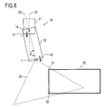
- Fig. 8 shows the articulated vehicle 10 along with the road surface around it as seen from above.
- a rectangular parking space frame 30 in a parking area is drawn on the road surface, behind the articulated vehicle 10, a rectangular parking space frame 30 in a parking area is drawn.
- the two which are located on the road surface comparatively close to the articulated vehicle 10 are referred to as the vertices 31 and 32 respectively.
- the broken-line triangle indicated by the reference sign 33 represents the field of view of the camera 1. It is here assumed that the field of view 33 covers the vertices 31 and 32 at both time points t1 and t2.
- the movement direction of the trailer 12 depends on the movement direction of the tractor 11 and the coupling angle ⁇ CN .
- the example taken up here is a case in which the coupling angle ⁇ CN is positive at time point t1 and the tractor 11 travels straight back between time points t1 and t2. In this case, between time points t1 and t2, the trailer 12 moves rearward, obliquely rightward.
- arrows 41 and 42 indicate the traveling direction of the tractor 11 and the trailer 12, respectively, between time points t1 and t2.
- Fig. 9(a) shows the shot image at time point t1
- Fig. 9(b) shows the shot image at time point t2.
- the reference signs 31a and 32a indicate the vertices 31 and 32, respectively, on the shot image at time point t1
- the reference signs 31b and 32b indicate the vertices 31 and 32, respectively, on the shot image at time point t2.
- Fig. 10(a) shows the bird's-eye view image at time point t1
- Fig. 10(b) shows the bird's-eye view image at time point t2.
- the reference signs 31c and 32c indicate the vertices 31 and 32, respectively, on the bird's-eye view image at time point t1; in Fig. 10(b) the reference signs 31d and 32d indicate the vertices 31 and 32, respectively, on the bird's-eye view image at time point t2.
- Fig. 11 shows an image 101 having the two bird's-eye view images shown in Figs. 10(a) and (b) overlaid on each other.
- the vertices 31 and 32 in Fig. 8 are taken as a first and a second characteristic point respectively.
- an arrow V 31 represents the movement vector of the first characteristic point on the bird's-eye view coordinate system between time points t1 and t2
- an arrow V 32 represents the movement vector of the second characteristic point on the bird's-eye view coordinate system between time points t1 and t2.
- a movement vector is synonymous with a motion vector.
- the movement vector V 31 is a vector representation of the displacement from the characteristic point 31c to the characteristic point 31d, and represents the direction and magnitude of the movement of the first characteristic point on the bird's-eye view coordinate system between time points t1 and t2.
- the movement vector V 32 is a vector representation of the displacement from the characteristic point 32c to the characteristic point 32d, and represents the direction and magnitude of the movement of the second characteristic point on the bird's-eye view coordinate system between time points t1 and t2.
- An optical flow is a set of a plurality of movement vectors, and the optical flow determined at step S12 includes the movement vectors V 31 and V 32 .
- the movement of a characteristic point on the bird's-eye view coordinate system results from the movement of the trailer 12 in the real space; in addition, the plane on which the bird's-eye view coordinate system is defined is parallel to the road surface; thus a vector having the opposite direction to the movement vectors V 31 and V 32 represents information on the movement (that is, movement information) of the trailer 12 between time points t1 and t2.
- this movement information on the trailer 12 is determined based on the optical flow.
- the movement information is represented by a vector V B in Fig. 11 .
- the vector V B is derived from the optical flow determined at step S12.
- the direction and magnitude of the vector V B represent the movement direction and movement amount of the trailer 12 on the bird's-eye view coordinate system between time points t1 and t2.
- the vector V B is derived, for example, based on one movement vector of interest (for example, V 31 or V 32 ) included in the optical flow determined at step S12.
- the magnitude of the vector V B is made equal to the magnitude of the one movement vector of interest
- the direction of the vector V B is made opposite to the direction of the one movement vector of interest.
- the vector V B may be derived based on a plurality of movement vectors (for example, V 31 and V 32 ) included in the optical flow determined at step S12.
- the magnitude of the vector V B is made equal to the magnitude of the average vector of the plurality of movement vectors
- the direction of the vector V B is made opposite to the direction of the average vector of the plurality of movement vectors.
- the image processor 2 detects the movement information of the tractor 11 between time points t1 and t2.
- This movement information of the tractor 11 is obtained from a rudder angle sensor and a speed sensor (neither is illustrated) of which both are provided on the articulated vehicle 10.
- a rudder angle sensor is a sensor that detects the rudder angle of the tractor 11;
- a speed sensor is a sensor that detects the movement speed of the tractor 11.
- the movement information of the tractor 11 includes the rudder angle of the tractor 11 between time points t1 and t2 as detected by the rudder angle sensor and the movement speed of the tractor 11 between time points t1 and t2 as detected by the speed sensor. Based on this movement information of the tractor 11 and the time difference ⁇ t between time points t1 and t2, the movement direction and movement amount of the tractor 11 in the real space between time points t1 and t2 are determined.
- the movement direction of the tractor 11 in the real space denotes the movement direction of the tractor 11 in the real space relative to the center line 21 in Fig. 5 .
- the image processor 2 transforms the vector representing the movement direction and movement amount of the tractor 11 in the real space to a vector V A on the bird's-eye view coordinate system. Since the plane on which the bird's-eye view coordinate system is defined is parallel to the road surface and the movement of the tractor 11 in the real space is across the road surface, based on the height H of the virtual camera and the like, the vector representing the movement direction and movement amount of the tractor 11 in the real space can be geometrically transformed to the vector V A .
- the vector V A represents the movement direction and movement amount of the tractor 11 on the bird's-eye view coordinate system between time points t1 and t2.
- the movement direction and movement amount of the coupling 14 coincide with the movement direction and movement amount of the tractor 11; thus, determining the movement direction and movement amount of the tractor 11 and the coupling angle ⁇ CN determines the movement direction and movement amount of the trailer 12 in the time span of interest. That is, when the movement direction and movement amount of the tractor 11 are taken as a first variable, the movement direction and movement amount of the trailer 12 are taken as a second variable, and the coupling angle ⁇ CN is taken as a third variable, then determining two of the first to third variables determines the remaining one.
- the image processor 2 estimates the coupling angle ⁇ CN at the current moment.
- the coupling angle ⁇ CN at the current moment denotes the coupling angle at time point t2, or the coupling angle between time points t1 and t2.
- Fig. 12 shows a relationship between the vector V A corresponding to the movement information of the tractor 11 and the vector V B (see Fig. 11 ) corresponding to the movement information of the trailer 12. In a case where the tractor 11 travels straight back between time points t1 and t2, substituting the vectors V A and V B in formula (8) below determines the coupling angle ⁇ CN .
- the movement direction and movement amount of the trailer 12 depend, not only on the movement direction and movement amount of the tractor 11 and on the coupling angle ⁇ CN , but also on the positional relationship between the coupling 14 and the wheels 13 (see Fig. 2 ) of the trailer 12, the shape of the trailer 12, etc.
- the coupling angle ⁇ CN is determined geometrically. Since the positional relationship between the coupling 14 and the wheels 13 and the shape of the trailer 12 are prescribed, once the movement information of the tractor 11 and the trailer 12 is determined, the coupling angle ⁇ CN is determined uniquely.
- the coupling angle ⁇ CN can be expressed as a function of the movement information of the tractor 11 and the trailer 12 (that is, the vectors V A and V B ).
- a lookup table is created which when fed with the movement information of the tractor 11 and the trailer 12 returns the corresponding coupling angle ⁇ CN , and the lookup table is previously stored within the image processor 2; then, at step S15, by use of the lookup table, the coupling angle ⁇ CN is estimated.
- step S16 based on the movement information of the tractor 11 detected at step S14 and the coupling angle ⁇ CN estimated at step S15, a predicted movement course of the trailer 12 is derived.
- the predicted movement course derived here is a course which the body of the trailer 12 is expected to travel on the bird's-eye view coordinate system after time point t2.
- the predicted movement course of the trailer 12 depends, not only on the rudder angle of the tractor 11 and on the coupling angle ⁇ CN , but also on the positional relationship between the coupling 14 and the wheels 13 (see Fig. 2 ) of the trailer 12, the shape of the trailer 12, etc.
- the predicted movement course is determined geometrically. Since the positional relationship between the coupling 14 and the wheels 13 and the shape of the trailer 12 are prescribed, once the rudder angle of the tractor 11 and the coupling angle ⁇ CN at a given time point are determined, the position of the body of the trailer 12 at that time point is determined uniquely. It is however necessary to take into consideration the fact that even when the rudder angle is held fixed, the coupling angle ⁇ CN changes constantly.
- the predicted movement course is derived through three stages of processing, namely Processing 1 to 3, as described below.
- Processing 1 For the purpose of deriving the predicted movement course, it is assumed that the tractor 11 continues to move while keeping the rudder angle and the movement speed as they are at the current moment even after time point t2. On this assumption, from the rudder angle of the tractor 11 and the coupling angle ⁇ CN as they are at the current moment, the coupling angles ⁇ CN at different time points in the future are estimated.
- a lookup table for this estimation may be previously created based on the positional relationship between the coupling 14 and the wheels 13, the shape of the trailer 12, etc. Instead, the lookup table may be created beforehand based on the actual results of road tests of the articulated vehicle 10.
- the coupling angles ⁇ CN at different time points in the future are estimated.
- Processing 2 Based on the rudder angle at the current moment and on the coupling angles ⁇ CN at different time points in the future as estimated through Processing 1, the movement directions of the trailer 12 on the bird's-eye view coordinate system in different time spans in the future are estimated.
- a lookup table for this estimation too is previously created based on the positional relationship between the coupling 14 and the wheels 13, the shape of the trailer 12, etc.
- Processing 3 Based on the movement directions of the trailer 12 on the bird's-eye view coordinate system, and the body positions of the trailer 12 on the bird's-eye view coordinate system, in different time spans in the future, a predicted movement course is derived. With the body position of the trailer 12 on the bird's-eye view coordinate system at time point t2 taken as a start point, by connecting together the movement directions of the trailer 12 in different time spans in the future, the predicted movement course is determined.
- the image processor 2 creates a display image that matches the predicted movement course determined at step S16. Specifically, the image processor 2 creates the display image by superimposing on the bird's-eye view image at time point t2 a vehicle guide line indicating a predicted movement course of the rear left corner of the body of the trailer 12 and a vehicle guide line indicating a predicted movement course of the rear right corner of the body of the trailer 12.
- the display image here too is, like bird's-eye view images, an image on the bird's-eye view coordinate system.
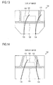
- Fig. 13 shows an example of the display image. It should be noted that, although the exterior shape of bird's-eye view images are rectangular in Figs. 10(a) and (b) , the exterior shape of bird's-eye view images may be other than rectangular.
- the exterior shape of the display image 120 shown in Fig. 13 is hexagonal. It should also be noted that it is for the sake of convenience of illustration that the display image 120 shown in Fig. 13 greatly differs from the bird's-eye view images shown in Figs. 10(a) and (b) .
- hatching indicates the region where white lines are drawn as parking space frames.
- the display image 120 is obtained by superimposing the vehicle guide lines 121 and 122 on the bird's-eye view image based on the shot image. Points 123 and 124 correspond to the rear left and right corners of the trailer 12 on the bird's-eye view image, and the distance between the points 123 and 124 represents the vehicle width of the trailer 12 on the bird's-eye view image.
- the vehicle guide lines 121 and 122 are drawn starting at the points 123 and 124.
- first and a second distance line which indicate distances from the rear end of the trailer 12.
- broken lines 125 and 126 extending in the lateral direction of the display image 120 are the first and second distance lines respectively.
- the first and second distance lines indicate, for example, distances of 1 m and 2 m, respectively, from the rear end of the trailer 12.
- a third distance line and a fourth distance line, and so forth may be additionally superimposed.
- a Z w -axis-direction coordinate Z w in the two-dimensional ground surface coordinate system X w Z w represents a distance from the rear end of the trailer 12, and therefore according to formula (4) or (5) above, the image processor 2 can determine the positions of the first and second distance lines on the display image.
- a broken line passing at the left ends of the broken lines 125 and 126 and at the point 123 and a broken line passing at the right ends of the broken lines 125 and 126 and at the point 124 correspond to extension lines of the left and right ends of the trailer 12.
- step S17 The display image generated at step S17 is displayed on the display screen of the display device 3. On completion of the processing at step S17, a return is made to step S11 so that the processing at steps S11 through S17 is executed repeatedly to display the display image based on the most recent shot image on the display device 3 in a constantly updated fashion.
- the display image is generated by superimposing additional information on a bird's-eye view image, and thus it is possible to offer to a driver an image which shows distances matched with actual distances and which thus permits easy grasping of the situation behind a vehicle.
- the movement information of the trailer 12 to be determined at step S13 in Fig. 7 is represented by the vector V B in Fig. 11 , and determining the movement vector V 31 and/or V 32 makes it possible to derive the vector V B . Accordingly, at steps S12 and S13 in Fig. 7 , the following processing may instead be executed.
- This modified example of the processing at steps S12 and S13 will now be described as Example 2.
- the vector V B is derived through the processing for extracting and tracking characteristic points. This derivation method may be considered to be included in the method for deriving the vector V B described with regard to Example 1.
- Example 2 is implemented in combination with Example 1, and unless inconsistent, any feature described with regard to Example 1 applies to this practical example.
- Example 2 after the shot images at time points t1 and t2 are acquired at step S11, at step S12, characteristic points are extracted from the shot image at time point t1.
- a characteristic point is a point that is distinguishable from surrounding points and that is easy to track.
- Such a characteristic point can be extracted automatically by use of a well-known characteristic point extractor (unillustrated) that detects a pixel exhibiting a large variation in density in the horizontal and vertical directions.
- characteristic point extractors include the Harris corner detector and the SUSAN corner detector.
- the characteristic points to be extracted are, for example, intersections and end points of white lines drawn on the road surface, and smudges and cracks on the road surface; that is, they are assumed to be immobile points with no height on the road surface.
- the processing for tracking characteristic points can be achieved by a well-known method.
- the tracking processing is achieved by comparing the first and second reference images with each other. More specifically, a region in the vicinity of the position of a characteristic point in the first reference image is taken as a characteristic point search region, and by performing image matching processing within a characteristic point search region in the second reference image, the position of a characteristic point in the second reference image is identified.
- a template is formed in the image within a rectangular region centered about the position of a characteristic point in the first reference image, and the degree of similarity of that template to the image within a characteristic point search region in the second reference image is calculated. From the calculated degree of similarity, the position of a characteristic point in the second reference image is identified.
- the position of a characteristic point in the shot image at time point t2 is determined.
- characteristic points 31a and 32a have been extracted from the shot image at time point t1 (see Fig. 9(a) ), and that through the tracking processing the positions of characteristic points 31b and 32b in the shot image at time point t2 have been determined (see Fig. 9(b) ).
- the image processor 2 transforms the shot images at time points t1 and t2 to the bird's-eye view images at time points t1 and t2 by bird's-eye transformation, and in addition maps the characteristic points 31 a, 32a, 31b, and 32b onto the bird's-eye view coordinate system according to formula (7) above to identify the positions of characteristic points 31c, 32c, 31d, and 32d on the bird's-eye view coordinate system.
- the movement vectors V 31 and V 32 are determined automatically, and thus based on the movement vectors V 31 and/or V 32 , the vector V B can be derived.
- the number of characteristic points extracted and tracked is two
- the vector V B can be derived when at least one of the movement vectors V 31 and V 32 is determined
- the number of characteristic points to be extracted and tracked may be one.
- the above example deals with a case in which the processing for extracting and tracking characteristic points is performed on the shot image, it may instead be performed on the bird's-eye view image. Specifically, in that case, after the shot images at time points t1 and t2 are transformed to the bird's-eye view images at time points t1 and t2 by bird's-eye transformation, by use of a characteristic point extractor, characteristic points 31c and 32c are extracted from the bird's-eye view image at time point t1 (see Fig. 10(a) ).
- Example 1 the display image is generated by superimposing vehicle guide lines on the bird's-eye view image. Since the bird's-eye view image is an image as seen when looking down to the ground surface from right above, it has the disadvantage of a narrow field of view. As an alternative, therefore, the display image may be generated by superimposing vehicle guide lines on an image other than the bird's-eye view image. This will now be described as Example 3. Specifically, for example, vehicle guide lines may be superimposed on the shot image as a source image, thereby to generate the display image. This makes it possible to offer an image with a wide field of view. Example 3 is implemented in combination with Example 1 or 2, and unless inconsistent, any feature described with regard to Example 1 or 2 applies to this practical example.
- Example 3 the vehicle guide lines determined through steps S11 through S16 in Fig. 7 are mapped onto the coordinate system of the shot image.
- This mapping is achieved through the inverse transformation of the coordinate transformation for transforming the shot image to the bird's-eye view image. For example, by inversely transforming the coordinates (x au , y au ) of the individual pixels forming the vehicle guide lines on the bird's-eye view image to coordinates (x bu , y bu ) on the shot image according to formula (7) above, the positions of the vehicle guide lines on the shot image are determined.
- Fig. 14 shows an example of the display image in this practical example.
- the display image 130 shown in Fig. 14 is obtained by superimposing vehicle guide lines 131 and 132 onto the shot image at time point t2. It should be noted that, for the sake of convenience of illustration, the shot image at time point t2 corresponding to Fig. 14 differs from the shot image at time point t2 corresponding to Fig. 9(b) .
- the vehicle guide lines 131 and 132 are the result of the vehicle guide lines 121 and 122 shown in Fig. 13 being mapped onto the coordinate system of the shot image.
- hatching indicates the region where white lines are drawn as parking space frames.
- Points 133 and 134 correspond to the rear left and right corners of the trailer 12 on the shot image, and the distance between the points 133 and 134 represents the vehicle width of the trailer 12.
- the vehicle guide lines 131 and 132 are drawn starting at the points 133 and 134.
- first and a second distance line which indicate distances from the rear end of the trailer 12.
- Broken lines 135 and 136 extending in the lateral direction of the display image 130 are the first and second distance lines respectively, and these correspond to the result of the broken lines 125 and 126 in Fig. 13 being mapped onto the shot image.
- a broken line passing at the left ends of the broken lines 135 and 136 and at the point 133 and a broken line passing at the right ends of the broken lines 135 and 136 and at the point 134 correspond to extension lines of the left and right ends of the trailer 12.
- Example 4 will now be described as a practical example to describe modified examples of the method for generating the display image. In the description of Example 4, applied examples of other than the method for generating the display image will be mentioned as well. Example 4 is implemented in combination with Examples 1 to 3, and unless inconsistent, any feature described with regard to Examples 1 to 3 applies to this practical example. Although three patterns of modified processing, namely Modified Processing 1 to 3, are discussed separately below, two or more patterns of modified processing may be implemented in combination.
- a sign indicating the movement direction (traveling direction) of the trailer 12 may be superimposed on the shot image or bird's-eye view image, thereby to generate the display image.
- Fig. 15 shows an example of such a display image.
- the display image 150 in Fig. 15 is an image obtained by superimposing on the bird's-eye view image at time point t2 shown in Fig. 10(b) an arrow 151 as a sign indicating the movement direction of the trailer 12.
- the direction of the arrow 151 coincides with the direction of the vector V B shown in Fig. 11 .
- the vector V B on the bird's-eye view coordinate system is transformed to a vector on the coordinate system of the shot image through the inverse transformation mentioned with regard to Example 3, and an arrow whose direction coincides with the direction of the thus obtained vector is superimposed on the shot image at time point t2 shown in Fig. 9(b) , thereby to generate the display image.
- a sign indicating the movement direction of the trailer 12 and vehicle guide lines may both be superimposed on the shot image or bird's-eye view image, thereby to generate the display image.
- the result of the estimation of the coupling angle ⁇ CN at step S15 in Fig. 7 may be reflected in the display image. How it is reflected in it is arbitrary.
- the coupling angle ⁇ CN has been estimated based on the shot images at time points t1 and t2.
- a value indicating the coupling angle ⁇ CN is superimposed on the shot image at time point t2 or on the bird's-eye view image at time point t2, thereby to generate the display image.
- a sign indicating the movement direction of the trailer 12 and/or vehicle guide lines may additionally be superimposed.
- the display image may instead be so generated that the shot image or bird's-eye view image at time point t2 and an illustration indicating the coupling angle ⁇ CN are displayed side by side on the display screen.
- Fig. 16 shows an example of such a display image.
- the display image 160 in Fig. 16 is divided into two regions 161 and 162.
- In the region 161 is shown the same image as the display image 130 shown in Fig. 14 (or an image obtained by compressing the display image 130 in the lateral direction), and in the region 162 is shown an illustration indicating the coupling angle ⁇ CN as most recently estimated.
- This illustration contains a picture of the articulated vehicle composed of the tractor and the trailer, and according to the coupling angle ⁇ CN , the coupling angle of the tractor and the trailer on the illustration varies.
- the driving assistance system (for example, the image processor 2) compares the coupling angle ⁇ CN estimated at step S15 in Fig. 7 with a predetermined threshold angle, and when the former is equal to or larger than the latter, gives an indication to notify the driver of the articulated vehicle 10 that the coupling angle ⁇ CN is excessively large.
- This indication may be by means of an image by use of the display device 3, or by means of a sound by use of an unillustrated speaker. Since the proper threshold angle varies with the sizes of the bodies of the tractor 11 and the trailer 12 etc., preferably, the threshold angle is changed according to the type etc. of the articulated vehicle 10.
- Example 5 is implemented in combination with Example 1, or with one of Examples 2 to 4. Discussed below will be the processing after the shot images at time points t1 and t2 have been acquired and the processing at steps S11 through S15 in Fig. 7 has been executed as described with regard to Example 1.
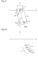
- Fig. 17 shows the bird's-eye view coordinate system having X au and Y au axes as its coordinate axes.
- Fig. 17 also shows figures obtained by projecting the articulated vehicle 10 onto the bird's-eye view coordinate system.
- the reference signs 11a, 12a, and 13a indicate the figures obtained by projecting the tractor 11, the trailer 12, and the wheels 13, respectively, in Fig. 2 onto the bird's-eye view coordinate system.
- the center of the axle of the two wheels 13 provided on the trailer 12 will be represented by Q.
- the axle of the two wheels 13 is perpendicular to the center line 22 in Fig. 5 , and the axle center Q lies on the center line 22.
- the tractor 11 continues to move while keeping the rudder angle and the movement speed as they are at the current moment even after time point t2. Then, the vector representing the movement direction and movement amount of the tractor 11 on the bird's-eye view coordinate system between time points t2 and t3 coincides with the vector V A between time points t1 and t2 mentioned with regard to Example 1. Accordingly, from the vector V A , the position k[t3] of the coupling 14 at time point t3 on the bird's-eye view coordinate system can be determined.
- the position of the end point of the vector V A when it is arranged on the bird's-eye view coordinate system with its start point placed at the position k[t2] of the coupling 14 at time point t2 is taken as the position k[t3]. It is here assumed that, once the rudder angle of the tractor 11 between time points t1 and t2 is determined, the direction of the vector V A on the bird's-eye view coordinate system is determined.
- the coupling angle ⁇ CN at time point ti is represented by ⁇ CN [ti] (where i is a natural number). Furthermore, the position of the axle center Q at time point ti on the bird's-eye view coordinate system is represented by Q[ti] (where i is a natural number).
- the coupling angle ⁇ CN [t2] at time point t2 has been estimated at step S15 in Fig. 7 , and by use of this coupling angle ⁇ CN [t2], the image processor 2 determines the position Q[t2]. More specifically, it determines the position Q[t2] based on the coupling angle ⁇ CN [t2], the position k[t2], and already known body information of the trailer 12.
- the body information of the trailer 12 identifies the distance from the coupling 14 to the axle center Q on the bird's-eye view coordinate system.
- the image processor 2 estimates the position Q[t3] of the axle center Q at time point t3 on the bird's-eye view coordinate system such that the following two conditions, namely a first and a second, are both fulfilled (refer to Japan Automobile Standards, JASO Z 006-92, page 18).
- the first condition is: "the distance between the position k[t2] and the position Q[t2] is equal to the distance between the position k[t3] and the position Q[t3].
- the second condition is: "the position Q[t3] lies on the line connecting between the position k[t2] and the position Q[t2].
- the image processor 2 estimates the coupling angle ⁇ CN [t3] at time point t3. Specifically, it estimates as the coupling angle ⁇ CN [t3] the angle formed by the straight line passing through the position k[t3] and parallel to Y au axis and the straight line connecting between the position k[t3] and the position Q[t3].
- Fig. 18 is a plotting of the positions Q[t2] to Q[t6] of the axle center Q at time points t2 to t6.
- the locus through Q[t2] to Q[t6] is the predicted movement course of the axle center Q on the bird's-eye view coordinate system.
- Curved lines 171 and 172 in Fig. 18 are the predicted movement courses of the rear left and right corners of the body of the trailer 12 after time point t2. These predicted movement courses are derived at step S16 in Fig. 7 .
- the display image 120 in Fig. 13 is generated by superimposing vehicle guide lines 121 and 122 along those curved lines 171 and 172 on the bird's-eye view image at time point t2.
- Example 6 will be described.
- Fig. 19 is a functional block diagram of the image processor 2 corresponding to Example 1.
- the image processor 2 in Fig. 19 is provided with blocks identified by the reference signs 201 to 205.
- the shot images at time points t1 and t2 acquired at step S11 in Fig. 7 are fed to a bird's-eye transformer 201.
- the bird's-eye transformer 201 transforms the shot images at time points t1 and t2 to the bird's-eye view images at time points t1 and t2 by bird's-eye transformation.
- a motion detector 202 compares with each other the bird's-eye view images at time points t1 and t2 resulting from the transformation, thereby to derive the optical flow on the bird's-eye view coordinate system between time points t1 and t2 (step S12).
- a coupling angle estimator 203 estimates the coupling angle ⁇ CN (step S15).
- the processing at steps S13 and S14 in Fig. 7 is achieved by the motion detector 202, or the coupling angle estimator 203, or another block within the image processor 2.
- a movement course estimator 204 executes the processing at step S16 in Fig. 7 , thereby to determine the predicted movement course of the trailer 12.
- a display image generator 205 By superimposing vehicle guide lines based on the result of the estimation on the bird's-eye view image at time point t2, a display image generator 205 generates the display image at time point t2.
- Fig. 20 additionally shows a trailer movement direction estimator 206, which also is provided, along with the blocks identified by the reference signs 201 to 205, within the image processor 2.
- the trailer movement direction estimator 206 determines the vector V B in Fig. 11 which represents the movement direction of the trailer 12.
- the display image generator 205 generates the display image 150 in Fig. 15 .
- the coordinate transform described above for generating a bird's-eye view image from a shot image is generally called perspective projection transformation.
- well-known planar projection transformation may be used to generate a bird's-eye view image from a shot image.
- a homography matrix coordinate transformation matrix
- the homograpy matrix is determined by a known method. Then, when the operation shown in Fig. 7 is performed, based on the homograpy matrix, a shot image is transformed to a bird's-eye view image. In any case, a shot image is transformed to a bird's-eye view image by projecting the shot image onto the bird's-eye view coordinate system.
- a display image based on the shot image obtained from a single camera is displayed on the display device 3; instead, in a case where the articulated vehicle 10 is fitted with a plurality of cameras (unillustrated), the display image may be generated based on a plurality of shot images obtained from the plurality of cameras.
- the display image may be generated based on a plurality of shot images obtained from the plurality of cameras.
- one or more other cameras are installed on the articulated vehicle 10, and an image based on the shot images from the other cameras and an image based on the shot image from the camera 1 are synthesized; it is then possible to take the resulting synthesized image as the display image eventually fed to the display device 3.
- the thus synthesized image is, for example, an all-around bird's-eye view image as described in JP-A-2006-287892 .
- a driving assistance system embodying the present invention is applied to an articulated vehicle 10 composed of a tractor 11 and a trailer 12 (see Fig. 2 ).
- the application of driving assistance systems embodying the invention is not limited to articulated vehicles composed of a tractor and a trailer.
- Driving assistance systems embodying the invention are applicable to any articulated vehicles composed of a first vehicle and a second vehicle coupled to and towed by the first vehicle.
- the first vehicle is exemplified by the tractor 11 and the second vehicle is exemplified by the trailer 12.
- the articulated vehicle 10 in Fig. 1 is a large articulated vehicle for transporting steel products and heavy loads, the present invention does not depend on the size of articulated vehicles.
- Articulated vehicles to which the present invention is applicable include vehicles generally called towing/towed automobiles (or, articulated vehicles themselves are towing/towed automobiles).
- articulated vehicles to which the present invention is applicable include articulated buses (coupled buses), connected buses, and tram buses, all composed of a first vehicle and a second vehicle.
- a driving assistance system embodying the present invention is applied to an articulated bus, with a first and a second vehicle of the articulated bus regarded as the tractor 11 and the trailer 12 described above, the processing described above can be performed.
- the present invention can be applied even to articulated vehicles classified as SUVs (sports utility vehicles).
- the image processor 2 in Fig. 1 can be realized in hardware, in software, or in a combination of hardware and software. All or part of the functions realized by the image processor 2 in Fig.1 may be prepared in the form of a software program so that this software program is executed on a computer to realize all or part of those functions.
Applications Claiming Priority (2)
| Application Number | Priority Date | Filing Date | Title |
|---|---|---|---|
| JP2007227635A JP2009060499A (ja) | 2007-09-03 | 2007-09-03 | 運転支援システム及び連結車両 |
| PCT/JP2008/064723 WO2009031400A1 (ja) | 2007-09-03 | 2008-08-19 | 運転支援システム及び連結車両 |
Publications (1)
| Publication Number | Publication Date |
|---|---|
| EP2181898A1 true EP2181898A1 (de) | 2010-05-05 |
Family
ID=40428721
Family Applications (1)
| Application Number | Title | Priority Date | Filing Date |
|---|---|---|---|
| EP08829242A Withdrawn EP2181898A1 (de) | 2007-09-03 | 2008-08-19 | Fahrunterstützungssystem und damit verbundene fahrzeuge |
Country Status (5)
| Country | Link |
|---|---|
| US (1) | US20100171828A1 (de) |
| EP (1) | EP2181898A1 (de) |
| JP (1) | JP2009060499A (de) |
| CN (1) | CN101795901A (de) |
| WO (1) | WO2009031400A1 (de) |
Cited By (11)
| Publication number | Priority date | Publication date | Assignee | Title |
|---|---|---|---|---|
| EP2394855A1 (de) * | 2010-06-12 | 2011-12-14 | ConWys AG | Rücksehhilfe für ein Fahrzeuggespann |
| WO2013079068A1 (en) * | 2011-11-28 | 2013-06-06 | Trailertrack Aps | A system for controlling the adjustment of a side rearview device |
| WO2014121810A1 (de) * | 2013-02-06 | 2014-08-14 | Volvo Construction Equipment Germany GmbH | Baumaschine mit einer überwachungseinrichtung |
| WO2015074027A1 (en) * | 2013-11-18 | 2015-05-21 | Robert Bosch Gmbh | Vector-based driver assistance for towing vehicle |
| US9082315B2 (en) | 2012-03-08 | 2015-07-14 | Industrial Technology Research Institute | Surrounding bird view monitoring image generation method and training method, automobile-side device, and training device thereof |
| GB2529408A (en) * | 2014-08-18 | 2016-02-24 | Jaguar Land Rover Ltd | Display system and method |
| EP2415038A4 (de) * | 2009-03-30 | 2016-10-26 | Delphi Tech Inc | Bedienungshilfe für ein verbundenes fahrzeug aus zwei elementen |
| FR3038279A1 (fr) * | 2015-07-03 | 2017-01-06 | Commissariat Energie Atomique | Procede de conduite automatique pour l'insertion et l'extraction d'un vehicule dans une station d'accueil, et dispositif de controle mettant en oeuvre un tel procede |
| DE102016109954A1 (de) * | 2016-05-31 | 2017-11-30 | Connaught Electronics Ltd. | Verfahren zum Unterstützen eines Fahrers eines Gespanns beim Rangieren des Gespanns, Fahrerassistenzsystem sowie Kraftfahrzeug |
| EP3226553B1 (de) * | 2017-02-09 | 2018-12-12 | Komatsu Ltd. | Umgebungsüberwachungssystem für arbeitsfahrzeug, arbeitsfahrzeug und umgebungsüberwachungsverfahren für ein arbeitsfahrzeug |
| US10701299B2 (en) | 2014-08-18 | 2020-06-30 | Jaguar Land Rover Limited | Display system and method |
Families Citing this family (119)
| Publication number | Priority date | Publication date | Assignee | Title |
|---|---|---|---|---|
| GB2447672B (en) | 2007-03-21 | 2011-12-14 | Ford Global Tech Llc | Vehicle manoeuvring aids |
| JP5190712B2 (ja) * | 2009-03-24 | 2013-04-24 | アイシン精機株式会社 | 障害物検出装置 |
| WO2011036892A1 (ja) * | 2009-09-24 | 2011-03-31 | パナソニック株式会社 | 運転支援表示装置 |
| CN102947515B (zh) * | 2010-06-18 | 2015-07-29 | 日立建机株式会社 | 作业机械的周围监视装置 |
| US20130002854A1 (en) * | 2010-09-17 | 2013-01-03 | Certusview Technologies, Llc | Marking methods, apparatus and systems including optical flow-based dead reckoning features |
| DE102011011048B9 (de) * | 2011-02-11 | 2021-10-07 | Mekra Lang Gmbh & Co. Kg | Überwachung des Nahbereichs rund um ein Nutzfahrzeug |
| US9290202B2 (en) | 2011-04-19 | 2016-03-22 | Ford Global Technologies, Llc | System and method of calibrating a trailer backup assist system |
| US9290204B2 (en) | 2011-04-19 | 2016-03-22 | Ford Global Technologies, Llc | Hitch angle monitoring system and method |
| US9555832B2 (en) | 2011-04-19 | 2017-01-31 | Ford Global Technologies, Llc | Display system utilizing vehicle and trailer dynamics |
| US9937953B2 (en) | 2011-04-19 | 2018-04-10 | Ford Global Technologies, Llc | Trailer backup offset determination |
| US9513103B2 (en) | 2011-04-19 | 2016-12-06 | Ford Global Technologies, Llc | Hitch angle sensor assembly |
| US9102271B2 (en) | 2011-04-19 | 2015-08-11 | Ford Global Technologies, Llc | Trailer monitoring system and method |
| US9374562B2 (en) | 2011-04-19 | 2016-06-21 | Ford Global Technologies, Llc | System and method for calculating a horizontal camera to target distance |
| US9283892B2 (en) | 2011-04-19 | 2016-03-15 | Ford Global Technologies, Llc | Method and system for monitoring placement of a target on a trailer |
| US9248858B2 (en) | 2011-04-19 | 2016-02-02 | Ford Global Technologies | Trailer backup assist system |
| US9434414B2 (en) | 2011-04-19 | 2016-09-06 | Ford Global Technologies, Llc | System and method for determining a hitch angle offset |
| US9854209B2 (en) * | 2011-04-19 | 2017-12-26 | Ford Global Technologies, Llc | Display system utilizing vehicle and trailer dynamics |
| US9335163B2 (en) | 2011-04-19 | 2016-05-10 | Ford Global Technologies, Llc | Trailer length estimation in hitch angle applications |
| US9506774B2 (en) | 2011-04-19 | 2016-11-29 | Ford Global Technologies, Llc | Method of inputting a path for a vehicle and trailer |
| US9683848B2 (en) | 2011-04-19 | 2017-06-20 | Ford Global Technologies, Llc | System for determining hitch angle |
| US9500497B2 (en) | 2011-04-19 | 2016-11-22 | Ford Global Technologies, Llc | System and method of inputting an intended backing path |
| US9290203B2 (en) | 2011-04-19 | 2016-03-22 | Ford Global Technologies, Llc | Trailer length estimation in hitch angle applications |
| US10196088B2 (en) | 2011-04-19 | 2019-02-05 | Ford Global Technologies, Llc | Target monitoring system and method |
| US9969428B2 (en) | 2011-04-19 | 2018-05-15 | Ford Global Technologies, Llc | Trailer backup assist system with waypoint selection |
| US9723274B2 (en) | 2011-04-19 | 2017-08-01 | Ford Global Technologies, Llc | System and method for adjusting an image capture setting |
| US9102272B2 (en) * | 2011-04-19 | 2015-08-11 | Ford Global Technologies, Llc | Trailer target monitoring system and method |
| US9346396B2 (en) | 2011-04-19 | 2016-05-24 | Ford Global Technologies, Llc | Supplemental vehicle lighting system for vision based target detection |
| US9926008B2 (en) | 2011-04-19 | 2018-03-27 | Ford Global Technologies, Llc | Trailer backup assist system with waypoint selection |
| AU2012257053A1 (en) * | 2011-05-13 | 2013-11-21 | Hitachi Construction Machinery Co., Ltd. | Device for monitoring area around working machine |
| DE102012200721A1 (de) * | 2012-01-19 | 2013-07-25 | Robert Bosch Gmbh | Verfahren zum Überwachen eines Fahrzeugumfeldes |
| FR2990662B1 (fr) * | 2012-05-16 | 2015-08-07 | Renault Sa | Camera de recul integree au logo |
| US9592851B2 (en) | 2013-02-04 | 2017-03-14 | Ford Global Technologies, Llc | Control modes for a trailer backup assist system |
| US9511799B2 (en) | 2013-02-04 | 2016-12-06 | Ford Global Technologies, Llc | Object avoidance for a trailer backup assist system |
| CN103234542B (zh) * | 2013-04-12 | 2015-11-04 | 东南大学 | 基于视觉的汽车列车弯道行驶轨迹测量方法 |
| US20150115571A1 (en) * | 2013-10-24 | 2015-04-30 | GM Global Technology Operations LLC | Smart tow |
| US9352777B2 (en) | 2013-10-31 | 2016-05-31 | Ford Global Technologies, Llc | Methods and systems for configuring of a trailer maneuvering system |
| JP6156067B2 (ja) | 2013-11-01 | 2017-07-05 | 富士通株式会社 | 移動量推定装置及び移動量推定方法 |
| DE102014000978A1 (de) * | 2014-01-25 | 2015-07-30 | Audi Ag | Verfahren und Vorrichtung zur Steuerung eines Gespanns in einen Parkraum |
| JP6313992B2 (ja) * | 2014-02-18 | 2018-04-18 | クラリオン株式会社 | 牽引車用周囲監視装置 |
| US9233710B2 (en) | 2014-03-06 | 2016-01-12 | Ford Global Technologies, Llc | Trailer backup assist system using gesture commands and method |
| US9296421B2 (en) | 2014-03-06 | 2016-03-29 | Ford Global Technologies, Llc | Vehicle target identification using human gesture recognition |
| JP2015186085A (ja) * | 2014-03-25 | 2015-10-22 | 富士通テン株式会社 | 移動量導出装置、及び、移動量導出方法 |
| US9963004B2 (en) | 2014-07-28 | 2018-05-08 | Ford Global Technologies, Llc | Trailer sway warning system and method |
| US9517668B2 (en) | 2014-07-28 | 2016-12-13 | Ford Global Technologies, Llc | Hitch angle warning system and method |
| US10112536B2 (en) | 2014-08-08 | 2018-10-30 | Bendix Commercial Vehicle Systems Llc | System and method for associating camera sensors on a vehicle |
| US9437055B2 (en) | 2014-08-13 | 2016-09-06 | Bendix Commercial Vehicle Systems Llc | Cabin and trailer body movement determination with camera at the back of the cabin |
| US20160048966A1 (en) | 2014-08-13 | 2016-02-18 | Bendix Commercial Vehicle Systems Llc | Learning the distance between cameras for articulated vehicles |
| WO2016028816A1 (en) | 2014-08-18 | 2016-02-25 | Trimble Navigation Limited | System and method for modifying onboard event detection and/or image capture strategy using external source data |
| US9714037B2 (en) | 2014-08-18 | 2017-07-25 | Trimble Navigation Limited | Detection of driver behaviors using in-vehicle systems and methods |
| US10161746B2 (en) | 2014-08-18 | 2018-12-25 | Trimble Navigation Limited | Systems and methods for cargo management |
| JP5949861B2 (ja) * | 2014-09-05 | 2016-07-13 | トヨタ自動車株式会社 | 車両の接近物体検出装置及び車両の接近物体検出方法 |
| US9487931B2 (en) | 2014-09-12 | 2016-11-08 | Caterpillar Inc. | Excavation system providing machine cycle training |
| DE102014218995A1 (de) | 2014-09-22 | 2016-03-24 | Robert Bosch Gmbh | Verfahren und Vorrichtung zur Bird-View-Darstellung eines Fahrzeuggespanns sowie nachrüstbare Kamera |
| US9315212B1 (en) | 2014-10-13 | 2016-04-19 | Ford Global Technologies, Llc | Trailer sensor module and associated method of wireless trailer identification and motion estimation |
| US9340228B2 (en) | 2014-10-13 | 2016-05-17 | Ford Global Technologies, Llc | Trailer motion and parameter estimation system |
| US9533683B2 (en) | 2014-12-05 | 2017-01-03 | Ford Global Technologies, Llc | Sensor failure mitigation system and mode management |
| US9522677B2 (en) | 2014-12-05 | 2016-12-20 | Ford Global Technologies, Llc | Mitigation of input device failure and mode management |
| US9607242B2 (en) | 2015-01-16 | 2017-03-28 | Ford Global Technologies, Llc | Target monitoring system with lens cleaning device |
| JP6448029B2 (ja) * | 2015-01-27 | 2019-01-09 | 日野自動車株式会社 | 連結車両の連結角取得装置及び連結車両の運転支援システム |
| US9522699B2 (en) | 2015-02-05 | 2016-12-20 | Ford Global Technologies, Llc | Trailer backup assist system with adaptive steering angle limits |
| US9616923B2 (en) | 2015-03-03 | 2017-04-11 | Ford Global Technologies, Llc | Topographical integration for trailer backup assist system |
| US9804022B2 (en) | 2015-03-24 | 2017-10-31 | Ford Global Technologies, Llc | System and method for hitch angle detection |
| US9860445B2 (en) | 2015-06-15 | 2018-01-02 | Bendix Commercial Vehicle Systems Llc | Dual node composite image system architecture |
| US10204159B2 (en) | 2015-08-21 | 2019-02-12 | Trimble Navigation Limited | On-demand system and method for retrieving video from a commercial vehicle |
| EP3342644B1 (de) * | 2015-08-27 | 2020-07-22 | Jvc Kenwood Corporation | Anzeigevorrichtung für fahrzeug und anzeigeverfahren für fahrzeug |
| US9896130B2 (en) | 2015-09-11 | 2018-02-20 | Ford Global Technologies, Llc | Guidance system for a vehicle reversing a trailer along an intended backing path |
| US10611407B2 (en) | 2015-10-19 | 2020-04-07 | Ford Global Technologies, Llc | Speed control for motor vehicles |
| US10384607B2 (en) | 2015-10-19 | 2019-08-20 | Ford Global Technologies, Llc | Trailer backup assist system with hitch angle offset estimation |
| US9836060B2 (en) | 2015-10-28 | 2017-12-05 | Ford Global Technologies, Llc | Trailer backup assist system with target management |
| US10017115B2 (en) | 2015-11-11 | 2018-07-10 | Ford Global Technologies, Llc | Trailer monitoring system and method |
| US10011228B2 (en) | 2015-12-17 | 2018-07-03 | Ford Global Technologies, Llc | Hitch angle detection for trailer backup assist system using multiple imaging devices |
| US9798953B2 (en) | 2015-12-17 | 2017-10-24 | Ford Global Technologies, Llc | Template matching solution for locating trailer hitch point |
| US9610975B1 (en) | 2015-12-17 | 2017-04-04 | Ford Global Technologies, Llc | Hitch angle detection for trailer backup assist system |
| US10155478B2 (en) | 2015-12-17 | 2018-12-18 | Ford Global Technologies, Llc | Centerline method for trailer hitch angle detection |
| US9934572B2 (en) | 2015-12-17 | 2018-04-03 | Ford Global Technologies, Llc | Drawbar scan solution for locating trailer hitch point |
| US9827818B2 (en) | 2015-12-17 | 2017-11-28 | Ford Global Technologies, Llc | Multi-stage solution for trailer hitch angle initialization |
| US9796228B2 (en) | 2015-12-17 | 2017-10-24 | Ford Global Technologies, Llc | Hitch angle detection for trailer backup assist system |
| JP6737288B2 (ja) | 2016-01-13 | 2020-08-05 | 株式会社ソシオネクスト | 周囲監視装置、画像処理方法、及び画像処理プログラム |
| US10005492B2 (en) | 2016-02-18 | 2018-06-26 | Ford Global Technologies, Llc | Trailer length and hitch angle bias estimation |
| DE102016003233A1 (de) * | 2016-03-16 | 2017-09-21 | Mekra Lang Gmbh & Co. Kg | Sichtsystem für ein Fahrzeug, insbesondere Nutzfahrzeug |
| US10112646B2 (en) | 2016-05-05 | 2018-10-30 | Ford Global Technologies, Llc | Turn recovery human machine interface for trailer backup assist |
| US10106193B2 (en) | 2016-07-01 | 2018-10-23 | Ford Global Technologies, Llc | Enhanced yaw rate trailer angle detection initialization |
| US10046800B2 (en) | 2016-08-10 | 2018-08-14 | Ford Global Technologies, Llc | Trailer wheel targetless trailer angle detection |
| US10276049B2 (en) * | 2016-08-29 | 2019-04-30 | Aptiv Technologies Limited | Camera based trailer identification and blind zone adjustment |
| US10721397B2 (en) * | 2016-09-01 | 2020-07-21 | Caterpillar Inc. | Image processing system using predefined stitching configurations |
| US10222804B2 (en) | 2016-10-21 | 2019-03-05 | Ford Global Technologies, Llc | Inertial reference for TBA speed limiting |
| KR102313026B1 (ko) * | 2017-04-11 | 2021-10-15 | 현대자동차주식회사 | 차량 및 차량 후진 시 충돌방지 보조 방법 |
| JP6897294B2 (ja) * | 2017-05-11 | 2021-06-30 | 株式会社アイシン | 牽引支援装置 |
| US10710585B2 (en) | 2017-09-01 | 2020-07-14 | Ford Global Technologies, Llc | Trailer backup assist system with predictive hitch angle functionality |
| GB2566524B (en) * | 2017-09-18 | 2021-12-15 | Jaguar Land Rover Ltd | Image processing method and apparatus |
| US10625782B2 (en) * | 2017-10-03 | 2020-04-21 | Aisin Seiki Kabushiki Kaisha | Surroundings monitoring apparatus |
| CN111108023B (zh) | 2017-10-10 | 2022-04-12 | 株式会社爱信 | 停车辅助装置 |
| JP7087332B2 (ja) | 2017-10-10 | 2022-06-21 | 株式会社アイシン | 運転支援装置 |
| US11193784B2 (en) * | 2017-10-13 | 2021-12-07 | Waymo Llc | End of trip sequence |
| JP6972938B2 (ja) * | 2017-11-07 | 2021-11-24 | 株式会社アイシン | 周辺監視装置 |
| WO2019130827A1 (ja) * | 2017-12-25 | 2019-07-04 | キヤノン株式会社 | 画像処理装置およびその制御方法 |
| KR102418030B1 (ko) * | 2017-12-27 | 2022-07-07 | 현대자동차주식회사 | 차량 및 그 제어 방법 |
| JP7016751B2 (ja) * | 2018-03-29 | 2022-02-07 | ヤンマーパワーテクノロジー株式会社 | 運転支援システム |
| JP7023788B2 (ja) * | 2018-05-16 | 2022-02-22 | フォルシアクラリオン・エレクトロニクス株式会社 | 牽引支援装置 |
| JP7081305B2 (ja) * | 2018-05-24 | 2022-06-07 | 株式会社アイシン | 周辺監視装置 |
| US10926759B2 (en) * | 2018-06-07 | 2021-02-23 | GM Global Technology Operations LLC | Controlling a vehicle based on trailer position |
| TW202001672A (zh) * | 2018-06-26 | 2020-01-01 | 大陸商上海蔚蘭動力科技有限公司 | 行車輔助系統及行車輔助系統的操作方法 |
| US10977867B2 (en) * | 2018-08-14 | 2021-04-13 | Goodrich Corporation | Augmented reality-based aircraft cargo monitoring and control system |
| US10838054B2 (en) | 2018-10-08 | 2020-11-17 | Aptiv Technologies Limited | Detection system and method |
| US11077795B2 (en) | 2018-11-26 | 2021-08-03 | Ford Global Technologies, Llc | Trailer angle detection using end-to-end learning |
| KR102232276B1 (ko) * | 2018-11-28 | 2021-03-25 | 오토아이티(주) | 트레일러 트럭용 어라운드 뷰 영상 제공 장치 및 방법 |
| US10829046B2 (en) | 2019-03-06 | 2020-11-10 | Ford Global Technologies, Llc | Trailer angle detection using end-to-end learning |
| GB2582541B (en) * | 2019-03-12 | 2022-03-09 | Jaguar Land Rover Ltd | Driver assistance method and apparatus |
| DE102019106275A1 (de) * | 2019-03-12 | 2020-09-17 | Wabco Gmbh | Erfassungssystem und Verfahren zum Ermitteln eines Knickwinkels zwischen zwei Teilfahrzeugen eines Fahrzeug-Gespanns sowie Fahrzeug- Gespann |
| JP7217577B2 (ja) * | 2019-03-20 | 2023-02-03 | フォルシアクラリオン・エレクトロニクス株式会社 | キャリブレーション装置、キャリブレーション方法 |
| DE102019122086A1 (de) * | 2019-08-16 | 2021-02-18 | Connaught Electronics Ltd. | Fahrerassistenz für eine Kombination |
| CN110719411B (zh) * | 2019-12-16 | 2020-04-03 | 长沙智能驾驶研究院有限公司 | 车辆的全景环视图像生成方法及相关设备 |
| EP4100921A1 (de) * | 2020-02-04 | 2022-12-14 | Volvo Truck Corporation | Verfahren zur anpassung eines überlagerten bildes eines bereichs hinter und entlang einer fahrzeugseite |
| CN111175733B (zh) * | 2020-02-05 | 2022-04-29 | 北京小马慧行科技有限公司 | 车身的角度的识别方法及装置、存储介质、处理器 |
| CN111487976B (zh) * | 2020-05-03 | 2022-11-18 | 哈尔滨工程大学 | 一种倒车轨迹跟踪方法 |
| DE102021201525A1 (de) * | 2021-02-17 | 2022-08-18 | Robert Bosch Gesellschaft mit beschränkter Haftung | Verfahren zur Ermittlung einer räumlichen Ausrichtung eines Anhängers |
| US11846947B2 (en) * | 2021-05-11 | 2023-12-19 | Cnh Industrial Canada, Ltd. | Systems and methods for an implement imaging system |
| JP2023172329A (ja) * | 2022-05-23 | 2023-12-06 | 株式会社ジェイテクト | 連結車両の制御装置、連結車両の制御方法、および連結車両の制御プログラム |
| CN115303291B (zh) * | 2022-10-12 | 2023-01-20 | 深圳海星智驾科技有限公司 | 拖挂车的挂车轨迹预测方法和装置、电子设备和存储介质 |
Family Cites Families (11)
| Publication number | Priority date | Publication date | Assignee | Title |
|---|---|---|---|---|
| DE19901953B4 (de) * | 1999-01-20 | 2014-02-06 | Robert Bosch Gmbh | Vorrichtung und Verfahren zur Stabilisierung eines Fahrzeuggespannes |
| JP2002359839A (ja) * | 2001-03-29 | 2002-12-13 | Matsushita Electric Ind Co Ltd | リアビューカメラの画像表示方法及びその装置 |
| DE20110339U1 (de) * | 2001-06-22 | 2002-10-24 | Mekra Lang Gmbh & Co Kg | Parkhilfe zur Verwendung in einem Kraftfahrzeug |
| JP2004252837A (ja) * | 2003-02-21 | 2004-09-09 | Denso Corp | 車両周辺表示装置および車両周辺表示プログラム |
| JP4639753B2 (ja) * | 2004-10-25 | 2011-02-23 | 日産自動車株式会社 | 運転支援装置 |
| JP4596978B2 (ja) | 2005-03-09 | 2010-12-15 | 三洋電機株式会社 | 運転支援システム |
| JP2006256544A (ja) | 2005-03-18 | 2006-09-28 | Aisin Seiki Co Ltd | 後退運転支援装置 |
| US7425889B2 (en) * | 2005-05-06 | 2008-09-16 | Delphi Technologies, Inc. | Vehicle turning assist system and method |
| GB2447672B (en) * | 2007-03-21 | 2011-12-14 | Ford Global Tech Llc | Vehicle manoeuvring aids |
| US7904222B2 (en) * | 2007-06-27 | 2011-03-08 | GM Global Technology Operations LLC | Trailer articulation angle estimation |
| DE102007040250A1 (de) * | 2007-08-27 | 2009-03-05 | Daimler Ag | Verfahren und Vorrichtung zur Fahrerunterstützung beim Rangieren eines Fahrzeuges oder Fahrzeuggespanns |
-
2007
- 2007-09-03 JP JP2007227635A patent/JP2009060499A/ja active Pending
-
2008
- 2008-08-19 US US12/676,285 patent/US20100171828A1/en not_active Abandoned
- 2008-08-19 CN CN200880105392A patent/CN101795901A/zh active Pending
- 2008-08-19 EP EP08829242A patent/EP2181898A1/de not_active Withdrawn
- 2008-08-19 WO PCT/JP2008/064723 patent/WO2009031400A1/ja active Application Filing
Non-Patent Citations (1)
| Title |
|---|
| See references of WO2009031400A1 * |
Cited By (24)
| Publication number | Priority date | Publication date | Assignee | Title |
|---|---|---|---|---|
| EP2415038A4 (de) * | 2009-03-30 | 2016-10-26 | Delphi Tech Inc | Bedienungshilfe für ein verbundenes fahrzeug aus zwei elementen |
| EP2394855A1 (de) * | 2010-06-12 | 2011-12-14 | ConWys AG | Rücksehhilfe für ein Fahrzeuggespann |
| WO2013079068A1 (en) * | 2011-11-28 | 2013-06-06 | Trailertrack Aps | A system for controlling the adjustment of a side rearview device |
| US9403484B2 (en) | 2011-11-28 | 2016-08-02 | Trailertrack Aps | System for controlling the adjustment of a side rearview device |
| US9082315B2 (en) | 2012-03-08 | 2015-07-14 | Industrial Technology Research Institute | Surrounding bird view monitoring image generation method and training method, automobile-side device, and training device thereof |
| US10458098B2 (en) | 2013-02-06 | 2019-10-29 | Volvo Construction Equiptment Germany GmbH | Construction machine having a monitoring device |
| WO2014121810A1 (de) * | 2013-02-06 | 2014-08-14 | Volvo Construction Equipment Germany GmbH | Baumaschine mit einer überwachungseinrichtung |
| WO2015074027A1 (en) * | 2013-11-18 | 2015-05-21 | Robert Bosch Gmbh | Vector-based driver assistance for towing vehicle |
| CN105829178A (zh) * | 2013-11-18 | 2016-08-03 | 罗伯特·博世有限公司 | 用于牵引车辆的基于矢量的驾驶辅助 |
| US9956909B2 (en) | 2013-11-18 | 2018-05-01 | Robert Bosch Gmbh | Vector-based driver assistance for towing vehicle |
| CN105829178B (zh) * | 2013-11-18 | 2018-06-15 | 罗伯特·博世有限公司 | 用于牵引车辆的基于矢量的驾驶辅助 |
| US10701299B2 (en) | 2014-08-18 | 2020-06-30 | Jaguar Land Rover Limited | Display system and method |
| GB2529408A (en) * | 2014-08-18 | 2016-02-24 | Jaguar Land Rover Ltd | Display system and method |
| US11553153B2 (en) | 2014-08-18 | 2023-01-10 | Jaguar Land Rover Limited | Display system and method |
| US10701300B2 (en) | 2014-08-18 | 2020-06-30 | Jaguar Land Rover Limited | Display system and method |
| GB2529408B (en) * | 2014-08-18 | 2019-01-30 | Jaguar Land Rover Ltd | Display system and method |
| EP3115280A1 (de) * | 2015-07-03 | 2017-01-11 | Commissariat A L'energie Atomique Et Aux Energies Alternatives | Automatisches steuerungsverfahren für das ein- und ausfahren eines fahrzeugs in eine aufnahmestation, und steuerungsvorrichtung für die umsetzung dieses verfahrens |
| US9933785B2 (en) | 2015-07-03 | 2018-04-03 | Commissariat A L'energie Atomique Et Aux Energies Alternatives | Automatic control method for the insertion and the extraction of a vehicle into and from a receiving station, and control device implementing a method of this kind |
| FR3038279A1 (fr) * | 2015-07-03 | 2017-01-06 | Commissariat Energie Atomique | Procede de conduite automatique pour l'insertion et l'extraction d'un vehicule dans une station d'accueil, et dispositif de controle mettant en oeuvre un tel procede |
| WO2017207522A1 (en) * | 2016-05-31 | 2017-12-07 | Connaught Electronics Limited | Method for assisting a driver of a vehicle/trailer combination in maneuvering the vehicle/trailer combination, driver assistance system as well as motor vehicle |
| US11161462B2 (en) | 2016-05-31 | 2021-11-02 | Connaught Electronics Limited | Method for assisting a driver of a vehicle/trailer combination in maneuvering the vehicle/trailer combination, driver assistance system as well as motor vehicle |
| DE102016109954A1 (de) * | 2016-05-31 | 2017-11-30 | Connaught Electronics Ltd. | Verfahren zum Unterstützen eines Fahrers eines Gespanns beim Rangieren des Gespanns, Fahrerassistenzsystem sowie Kraftfahrzeug |
| US10421400B2 (en) | 2017-02-09 | 2019-09-24 | Komatsu Ltd. | Surroundings monitoring system for work vehicle, work vehicle, and surroundings monitoring method for work vehicle |
| EP3226553B1 (de) * | 2017-02-09 | 2018-12-12 | Komatsu Ltd. | Umgebungsüberwachungssystem für arbeitsfahrzeug, arbeitsfahrzeug und umgebungsüberwachungsverfahren für ein arbeitsfahrzeug |
Also Published As
| Publication number | Publication date |
|---|---|
| US20100171828A1 (en) | 2010-07-08 |
| WO2009031400A1 (ja) | 2009-03-12 |
| CN101795901A (zh) | 2010-08-04 |
| JP2009060499A (ja) | 2009-03-19 |
Similar Documents
| Publication | Publication Date | Title |
|---|---|---|
| EP2181898A1 (de) | Fahrunterstützungssystem und damit verbundene fahrzeuge | |
| KR100414708B1 (ko) | 화상합성장치 및 방법 | |
| US8233045B2 (en) | Method and apparatus for distortion correction and image enhancing of a vehicle rear viewing system | |
| US10434945B2 (en) | Method and device for displaying an image of the surroundings of a vehicle combination | |
| JP4899424B2 (ja) | 物体検出装置 | |
| US20090015675A1 (en) | Driving Support System And Vehicle | |
| CN111046743B (zh) | 一种障碍物信息标注方法、装置、电子设备和存储介质 | |
| US20170140542A1 (en) | Vehicular image processing apparatus and vehicular image processing system | |
| US20050074143A1 (en) | Vehicle backing assist apparatus and vehicle backing assist method | |
| EP1249365A1 (de) | Hilfsvorrichtung zur Steuerung eines Kraftfahrzeuges | |
| US11263758B2 (en) | Image processing method and apparatus | |
| JP4797877B2 (ja) | 車両用映像表示装置及び車両周囲映像の表示方法 | |
| JP2009206747A (ja) | 車両用周囲状況監視装置及び映像表示方法 | |
| US9682655B2 (en) | Method and device for operating a vehicle | |
| WO2014171100A1 (ja) | 車両用画像処理装置 | |
| US11833968B2 (en) | Imaging system and method | |
| JP2004240480A (ja) | 運転支援装置 | |
| CN109345591A (zh) | 一种车辆自身姿态检测方法和装置 | |
| JP3521859B2 (ja) | 車両周辺画像処理装置及び記録媒体 | |
| JP4256992B2 (ja) | 障害物検出装置 | |
| JP4720446B2 (ja) | 車両検出装置及びこれを用いた車両用表示装置 | |
| JP3395393B2 (ja) | 車両周囲表示装置 | |
| JP5155204B2 (ja) | 白線検出装置 | |
| JP4677820B2 (ja) | 予測進路表示装置および予測進路表示方法 | |
| JP4106163B2 (ja) | 障害物検出装置及びその方法 |
Legal Events
| Date | Code | Title | Description |
|---|---|---|---|
| PUAI | Public reference made under article 153(3) epc to a published international application that has entered the european phase |
Free format text: ORIGINAL CODE: 0009012 |
|
| 17P | Request for examination filed |
Effective date: 20100226 |
|
| AK | Designated contracting states |
Kind code of ref document: A1 Designated state(s): AT BE BG CH CY CZ DE DK EE ES FI FR GB GR HR HU IE IS IT LI LT LU LV MC MT NL NO PL PT RO SE SI SK TR |
|
| AX | Request for extension of the european patent |
Extension state: AL BA MK RS |
|
| DAX | Request for extension of the european patent (deleted) | ||
| STAA | Information on the status of an ep patent application or granted ep patent |
Free format text: STATUS: THE APPLICATION HAS BEEN WITHDRAWN |
|
| 18W | Application withdrawn |
Effective date: 20111223 |