EP2181736B1 - talonnière avec deux axes d'ouverture - Google Patents
talonnière avec deux axes d'ouverture Download PDFInfo
- Publication number
- EP2181736B1 EP2181736B1 EP08168072A EP08168072A EP2181736B1 EP 2181736 B1 EP2181736 B1 EP 2181736B1 EP 08168072 A EP08168072 A EP 08168072A EP 08168072 A EP08168072 A EP 08168072A EP 2181736 B1 EP2181736 B1 EP 2181736B1
- Authority
- EP
- European Patent Office
- Prior art keywords
- release mechanism
- mechanism according
- frame
- tap
- ski
- Prior art date
- Legal status (The legal status is an assumption and is not a legal conclusion. Google has not performed a legal analysis and makes no representation as to the accuracy of the status listed.)
- Not-in-force
Links
Images

Classifications
-
- A—HUMAN NECESSITIES
- A63—SPORTS; GAMES; AMUSEMENTS
- A63C—SKATES; SKIS; ROLLER SKATES; DESIGN OR LAYOUT OF COURTS, RINKS OR THE LIKE
- A63C9/00—Ski bindings
- A63C9/02—Non-self-releasing bindings with swivel sole-plate or swivel parts, i.e. Ellefsen-type
-
- A—HUMAN NECESSITIES
- A63—SPORTS; GAMES; AMUSEMENTS
- A63C—SKATES; SKIS; ROLLER SKATES; DESIGN OR LAYOUT OF COURTS, RINKS OR THE LIKE
- A63C9/00—Ski bindings
- A63C9/08—Ski bindings yieldable or self-releasing in the event of an accident, i.e. safety bindings
- A63C9/0807—Ski bindings yieldable or self-releasing in the event of an accident, i.e. safety bindings for both towing and downhill skiing
-
- A—HUMAN NECESSITIES
- A63—SPORTS; GAMES; AMUSEMENTS
- A63C—SKATES; SKIS; ROLLER SKATES; DESIGN OR LAYOUT OF COURTS, RINKS OR THE LIKE
- A63C9/00—Ski bindings
- A63C9/08—Ski bindings yieldable or self-releasing in the event of an accident, i.e. safety bindings
- A63C9/084—Ski bindings yieldable or self-releasing in the event of an accident, i.e. safety bindings with heel hold-downs, e.g. swingable
- A63C9/0844—Ski bindings yieldable or self-releasing in the event of an accident, i.e. safety bindings with heel hold-downs, e.g. swingable the body pivoting about a transverse axis
-
- A—HUMAN NECESSITIES
- A63—SPORTS; GAMES; AMUSEMENTS
- A63C—SKATES; SKIS; ROLLER SKATES; DESIGN OR LAYOUT OF COURTS, RINKS OR THE LIKE
- A63C9/00—Ski bindings
- A63C9/08—Ski bindings yieldable or self-releasing in the event of an accident, i.e. safety bindings
- A63C9/084—Ski bindings yieldable or self-releasing in the event of an accident, i.e. safety bindings with heel hold-downs, e.g. swingable
- A63C9/0845—Ski bindings yieldable or self-releasing in the event of an accident, i.e. safety bindings with heel hold-downs, e.g. swingable the body or base or a jaw pivoting about a vertical axis, i.e. side release
-
- A—HUMAN NECESSITIES
- A63—SPORTS; GAMES; AMUSEMENTS
- A63C—SKATES; SKIS; ROLLER SKATES; DESIGN OR LAYOUT OF COURTS, RINKS OR THE LIKE
- A63C9/00—Ski bindings
- A63C9/08—Ski bindings yieldable or self-releasing in the event of an accident, i.e. safety bindings
- A63C9/084—Ski bindings yieldable or self-releasing in the event of an accident, i.e. safety bindings with heel hold-downs, e.g. swingable
- A63C9/0846—Details of the release or step-in mechanism
-
- A—HUMAN NECESSITIES
- A63—SPORTS; GAMES; AMUSEMENTS
- A63C—SKATES; SKIS; ROLLER SKATES; DESIGN OR LAYOUT OF COURTS, RINKS OR THE LIKE
- A63C9/00—Ski bindings
- A63C9/005—Ski bindings with means for adjusting the position of a shoe holder or of the complete binding relative to the ski
Definitions
- the invention relates to a triggering machine for a ski touring binding.
- Ski touring bindings are for example from the EP 0 754 079 B1 or the EP 1 559 455 known.
- Modern ski touring bindings support two modes, namely a climbing mode and a departure mode.
- a climbing mode the functionality of a ski touring binding differs only slightly from that of a normal alpine sports binding.
- the heel of the ski boot and its front part are fixed, medium or directly connected to the ski touring ski to allow optimum power transfer to the ski.
- climbing mode it is necessary to loosen the connection at the heel in order to perform a usual walking movement during the ascent, in which the ski boot is tilted about an axis of rotation which is preferably close, immediately below or behind the ski boot tip.
- ski touring bindings include a backing plate on which toe and heel are mounted, with the boot remaining firmly attached to both sides during the climb mode as well as during downhill mode.
- the support plate is connected via a joint at the front with the ski.
- a shutter mechanism At the rear end of the support plate is a shutter mechanism, which makes it possible to firmly connect this end of the support plate with the ski.
- This compound is detachable, making the bond a comfortable one Walking with the ski allows.
- the plate fixation at the rear end of the ski at the same time provides a climbing aid that facilitates the climb, especially on steep terrain.
- Modern ski touring bindings are subject to numerous requirements. They are not only easy to use, in particular to ensure a quick and easy change between the climbing mode and the departure mode, but also be very robust and lightweight. On the one hand, it is easy to see that every extra gram of binding adds extra force to the ascent. On the other hand, you do not want to miss out on the usual alpine skiing comfort on the downhill.
- the ski touring bindings are so robust and optimized with regard to their power transmission to the ski that they can also be used in alpine skiing. Furthermore, the ski touring bindings should be so sure that a reliable triggering of the bond is guaranteed in order to avoid injury to the ski touring tracker.
- a central idea of the present invention is therefore to design the frame or the frame element integrally and / or in one piece. This ensures not only a horizontal release of the binding, in which the ski boot heel jumps up out of the binding, but also a vertical release, in which the shoe is released by a rotation of the ski. It can be implemented as a much more robust structure of the ski touring binding.
- the frame and other components of the triggering machine can be made of metal and / or plastic.
- plastic production is much cheaper than other materials.
- the individual moldings can be produced, for example, by injection molding. Furthermore, plastic parts do not oxidize. Thus, a longevity of the ski touring binding is ensured despite a permanent use in the snow.
- the second receiving area may comprise detents for releasably fixing the clamping lever.
- the detents allow a secure fixation of the clamping lever in the fixing position.
- the detents can be arranged such that a very stable fixation of the ski boot is ensured.
- the triggering process can be designed such that for the initiation of this process, a relatively high expenditure of force is necessary, which decreases after exceeding the catch or detents. So as far as the necessary force has been applied to trigger, it is ensured that it comes to a complete triggering of the ski touring binding.
- the horizontal opening may include a first horizontal opening section and a second horizontal opening section opening into and symmetrically formed in the vertical opening.
- the horizontal opening for receiving the clamping device and the vertical opening for receiving the pin can thus be arranged substantially perpendicular to one another within a plane.
- the individual channels overlap and it is possible that the clamping device acts directly on the pin or its receiving area.
- the vertical opening is arranged centrally in the base, wherein on both sides a horizontal opening section extends, which is preferably open to the outside.
- the horizontal opening can thus be a continuous opening, which preferably extends horizontally through the base.
- the clamping device can be symmetrically arranged around the pin. In this way, a much better and more powerful triggering mechanism can be provided. As far as the clamping device is accessible from the outside in the horizontal opening, a simple maintenance and adjustment of the clamping device can be made to a respective mixed release force.
- the tensioning lever can at least partially surround the cross member to form a pivot joint.
- the rotatable mounting of the clamping lever on the cross member can be made very simple.
- the cross member may comprise a convex outer shell for the rotation of the clamping lever about the horizontal axis in sections or be designed as part of a cylinder.
- the tensioning lever can engage with a concave portion in the convex portion of the outer shell and be guided by this.
- Cross member and clamping lever thus form a hinge in which the clamping lever rotates about the cross member.
- the frame may include a further horizontal opening extending through the cross member.
- the tensioning lever may comprise a clamping piston, which is biased against the cross member and engages at least in the fixing position in the second receiving area.
- the clamping piston and the receiving area of the cross member thus form the vertical triggering automatic.
- a spring force acting on the clamping piston at least partially overcome.
- the first receiving area may comprise a bottom portion and at least one ramp portion arranged in such a way, in particular parallel to the longitudinal axis of the pin, that the piston slides up the ramp portion upon initiation of the rotation from the starting position.
- the one or more ramp sections can perform the same function as the already described notches. However, the ramp sections secure the binding against unwanted horizontal release, in which the frame makes a torsional movement about the pin.
- the support plate may include a hinge for rotatably mounting to a ski, in particular ski touring skis. Although it is consistently spoken here of a support plate, it is obvious that this support plate does not necessarily have to be flat. It is possible to use a frame as a support plate on which the pin and the triggering machine are mounted.
- the carrier plate can also be a rail with a round, rectangular or square cross section, which is suitable to receive the triggering machine. Other geometric formations The support plate are conceivable and should also be understood as a support plate.
- the pin may comprise two second receiving areas, engage in the mutually arranged to the pin in the horizontal opening pin piston.
- a higher clamping force can be exerted on the second receiving areas.
- the pin is centered within the vertical opening, thereby preventing wedging in a tripping operation.
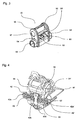
- Fig. 1 illustrates the already described in the introduction general structure of a ski touring binding 1.
- This includes a support plate 10, which in its front region (facing the tip of the ski) via a vertical joint 2 with a ski is connectable.
- the support plate 10 In its rear area, the support plate 10 can be locked via a plate fixing 80.
- the plate fixation is detachable and allows switching between a climbing mode and a downhill mode. In climbing mode, the plate fixing 80 can be folded after opening this forward so that it serves as a climbing aid.
- the heel unit 20 includes a tension lever 30 rotatably mounted on a frame 90.
- the tensioning lever 30 can therefore be brought into two positions substantially. In an entry position, the rear part of the clamping lever 30 is folded away to the rear. It is possible to enter the ski tour binding 1. In a second position, the fixing position, the rear part of the tensioning lever 30 is in a substantially horizontal position and fixes the ski boot between the toe 60 and the automatic heel 20, in particular between the toe 60 and in the front region of the tensioning lever 30 Fixierbacken 31st
- the pivot between the frame 90 and the tension lever 30 is formed by a cross member 92 having a substantially semicircular shape in cross section.
- a lower portion is convex
- an upper portion of the cross member 92 is flattened and together with two notches 95, 95 '(see. Fig. 3 ) a recording area.
- a clamping piston 32 In this receiving area engages in the fixing position a clamping piston 32, which is biased by a spring element (not shown) in the direction of the cross member 92 to.
- the clamping piston 32 moves in the clamping lever upwards and thus overcomes the Rear catch 95 on the cross member 92.
- the convex or partially cylindrical portion of the carrier 92 guides the tensioning lever 30 in this rotational movement.
- the fixing jaws 31 fixed to one end of the tensioning lever 30 hold the ski boot (not shown) firmly in the binding.
- the pivot formed by the clamping piston 32 and the cross member 92 not only serve for controlled boarding and disembarking from the ski touring binding 1.
- the hinge with the fixation simultaneously provides a vertical triggering mechanism in which upon the occurrence of a predetermined force (in the vertical direction) the tension lever 30 is released from its fixation by the tensioning piston 32 so that the ski boot is released in the entry position.
- the automatic heel unit 20 also provides a triggering mechanism in the horizontal plane. That is, the heel of the ski boot or the whole shoe can perform a rotational movement, which frees them from the ski touring binding 1.
- the frame 90 is rotatably arranged about a vertical axis on the support plate 10, in particular on a pin 50 attached thereto.
- the automatic heel unit 20 can therefore also occupy two positions, a starting position (fixing jaws 31, carrier plate 10 and toe jaws 60 lie substantially on one axis) and a release position (the automatic heel 20 is rotated relative to the carrier plate 10).
- This triggering mechanism is provided by the frame 90 and the pin 50.
- the pin 50 stores in a vertical axis hole 99 (see. Fig. 3 ) of the frame 90.
- the pin 50 may be an integral part of the support plate or screwed or glued to this.
- the pin 50 has, as in the FIGS. 5 and 6 shown in the plan view (view plane same carrier plate plane) has a substantially elongated shape which extends along the longitudinal axis of the support plate 10. This results in receiving areas 54, 54 ', in the piston 42, 42' engage.
- the second piston 42 ' comprises the shells 42a' and 42b ', which surround the second spring element 49'.
- the first shells 42a and 42a ' are bolted to the frame 90 such that the spring members 49, 49' are tensioned and press with their spring force on the second shells 42b and 42b 'engaged in the receiving portions 54, 54'.
- the spring force acting on the second shells 42b, 42b ' can be adjusted by turning the first shells 42a, 42a' in a thread provided for this purpose.
- the distance between the first shell 42a and the second shell 42b of the first piston 42 and that of the first shell 42a 'and the second shell 42b' of the second piston 42 is thus shortened or extended, whereby the first spring element 49 and the second spring element 49 'tense or relaxed.
- the frame 90 is composed of the cross member 92, the base 96 and the side members 94, 94 'together.
- the cross member 92 has a cavity, namely a horizontal axis hole 97 which extends parallel to the horizontal plane of the support plate 10 therethrough.
- Said elements are integrally connected to each other and here for example made of plastic by injection molding.
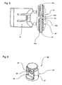
- the spring elements 49, 49 ' can be stretched and relaxed separately, shows the Fig. 5 a cross section through an automatic heel 20, in which the first shells 42a and 42a 'are connected to each other via a clamping screw 45.
- Fig. 6 shows the pin 50 from the Fig. 5 in a side view. It can be the flattened receiving areas 54, 54 'recognize, which are completed at their edges by ramp sections 57, 57'.
- the bore 55 allows the insertion or dipping of the clamping screw 45, wherein the bore 55 is designed such that a rotation of the frame 90 is possible.
- heel punches 20 have been described which include two pistons 42, 42 'for biasing the heel counter to a home position. It is conceivable to provide only one piston 42.
- the piston bore 98 extends in the described embodiments perpendicular to the longitudinal direction of the support plate 10. It is also conceivable to provide a piston bore 98 which extends substantially parallel to the longitudinal direction of the support plate 10. The pin 50 would then have to be adjusted accordingly. In another embodiment, the piston bore 98 may open into the vertical axis bore 99 at a non-orthogonal angle
Landscapes
- Footwear And Its Accessory, Manufacturing Method And Apparatuses (AREA)
- Fittings On The Vehicle Exterior For Carrying Loads, And Devices For Holding Or Mounting Articles (AREA)
Claims (12)
- Déclencheur automatique pour une fixation de ski de randonnée, comprenant:- une plaque de support (10),- un tourillon (50) relié à la plaque de support (10) et s'étendant essentiellement dans la direction verticale par rapport à la plaque de support (10),- un cadre (90) logé sur le tourillon (50) de manière à être pivotable autour d'un axe vertical,- un levier tendeur (30) présentant au moins un dispositif de fixation (31), ledit levier tendeur étant arrangé sur le cadre de manière à pouvoir pivoter autour d'un axe horizontal,le cadre présentant:- une base (96) avec une ouverture verticale (99) pour la réception du tourillon (50),- une ouverture horizontale (98) pour la réception d'un dispositif de serrage qui est en communication fonctionnelle avec au moins une première zone de réception (54, 54') au tourillon (50) si bien que le cadre (90) est fixé dans une position initiale et en franchissant une force définie peut tourner autour de l'axe vertical dans une position de déclenchement,- un élément transversal (92) avec au moins une deuxième zone de réception pour une fixation débrayable du levier tendeur (32) dans une position de fixation, l'élément transversal (92) étant relié à la base (96) intégralement sur au moins deux parties latérales (94, 94'), et le cadre (90) étant formé comme un composant intégral et préférablement fait en une seule pièce.
- Déclencheur automatique selon la revendication 1, caractérisé en ce que le cadre (90) est fait de métal ou de matière plastique.
- Déclencheur automatique selon la revendication 1 ou 2, caractérisé en ce que la deuxième zone de réception comprend des rainures (95, 95') pour la fixation débrayable du levier tendeur (45).
- Déclencheur automatique selon l'une quelconque des revendications précédentes, caractérisé en ce que l'ouverture horizontale (98) comprend une première section d'ouverture horizontale et une deuxième section d'ouverture horizontale qui aboutissent dans l'ouverture verticale (99) et sont formées symétriquement par rapport à celle-là.
- Déclencheur automatique selon l'une quelconque des revendications précédentes, caractérisé en ce que l'ouverture horizontale (98) est une ouverture s'étendant à travers la base (96).
- Déclencheur automatique selon l'une quelconque des revendications précédentes, caractérisé en ce que le levier tendeur (30) empoigne au moins partiellement l'élément transversal (92) pour former un joint articulé.
- Déclencheur automatique selon l'une quelconque des revendications précédentes, caractérisé en ce que l'élément transversal (92) comprend partiellement une enveloppe extérieure et convexe pour la rotation du levier tendeur (30) autour de l'axe horizontal.
- Déclencheur automatique selon l'une quelconque des revendications précédentes, caractérisé en ce que le cadre (90) comprend une ouverture horizontale supplémentaire (97) s'étendant à travers l'élément transversal (92).
- Déclencheur automatique selon l'une quelconque des revendications précédentes, caractérisé en ce que le levier tendeur (30) comprend un piston tendeur (32) étant précontraint contre l'élément transversal (92) et étant en prise avec la deuxième zone de réception au moins dans la position de fixation.
- Déclencheur automatique selon l'une quelconque des revendications précédentes, caractérisé en ce que la première zone de réception (54, 54') comprend une portion de fond et au moins une portion de rampe (57) qui est arrangée notamment parallèlement à l'axe longitudinal du tourillon (50) si bien que le piston (42, 42') au début de la rotation glisse hors de la position initiale et vers le haut dans la portion de rampe (57).
- Déclencheur automatique selon l'une quelconque des revendications précédentes, caractérisé en ce que la plaque de support (10) comprend un joint pour la fixation à pivotement à un ski, en particulier à un ski pour faire le ski de randonnée.
- Déclencheur automatique selon l'une quelconque des revendications précédentes, caractérisé en ce que le tourillon comprend deux deuxièmes zones de réception (54, 54') dans lesquelles s'engagent les pistons de tourillon (42, 42') arrangés dans l'ouverture horizontale alternativement par rapport au tourillon (50).
Priority Applications (2)
| Application Number | Priority Date | Filing Date | Title |
|---|---|---|---|
| EP08168072A EP2181736B1 (fr) | 2008-10-31 | 2008-10-31 | talonnière avec deux axes d'ouverture |
| US12/609,103 US20100276908A1 (en) | 2008-10-31 | 2009-10-30 | Automatic Release Device |
Applications Claiming Priority (1)
| Application Number | Priority Date | Filing Date | Title |
|---|---|---|---|
| EP08168072A EP2181736B1 (fr) | 2008-10-31 | 2008-10-31 | talonnière avec deux axes d'ouverture |
Publications (2)
| Publication Number | Publication Date |
|---|---|
| EP2181736A1 EP2181736A1 (fr) | 2010-05-05 |
| EP2181736B1 true EP2181736B1 (fr) | 2012-08-08 |
Family
ID=40380008
Family Applications (1)
| Application Number | Title | Priority Date | Filing Date |
|---|---|---|---|
| EP08168072A Not-in-force EP2181736B1 (fr) | 2008-10-31 | 2008-10-31 | talonnière avec deux axes d'ouverture |
Country Status (2)
| Country | Link |
|---|---|
| US (1) | US20100276908A1 (fr) |
| EP (1) | EP2181736B1 (fr) |
Families Citing this family (3)
| Publication number | Priority date | Publication date | Assignee | Title |
|---|---|---|---|---|
| EP2329864B1 (fr) * | 2009-09-30 | 2014-02-19 | MARKER Deutschland GmbH | Fixation de ski dotée d'une structure en cage |
| DE102010028764A1 (de) * | 2010-05-07 | 2011-11-10 | Salewa Sport Ag | Ferseneinheit für eine Bindung, insbesondere Tourenskibindung |
| CH708560A1 (de) * | 2013-09-11 | 2015-03-13 | Fritschi Ag Swiss Bindings | Vorderbacken für eine Skibindung. |
Family Cites Families (18)
| Publication number | Priority date | Publication date | Assignee | Title |
|---|---|---|---|---|
| DE2010795A1 (de) * | 1962-02-07 | 1971-09-23 | Unger, Paul, 8501 Altenberg | Auslösender Fersenniederhalter |
| FR2231402A1 (en) * | 1973-06-01 | 1974-12-27 | Campagnola Gabriel | Ski shoe fixing climb to descent position - is adjusted by ski stick and has progressively self releasing foot stop |
| US3918732A (en) * | 1974-03-18 | 1975-11-11 | Elmer B Wulf | Safety binding for skis |
| FR2424037B1 (fr) * | 1978-04-28 | 1982-12-17 | Salomon & Fils F | |
| AT370333B (de) * | 1979-10-05 | 1983-03-25 | Tyrolia Freizeitgeraete | Sicherheitsskibindung |
| DE3141021A1 (de) * | 1981-10-15 | 1983-04-28 | Etablissements François Salomon et Fils, 74011 Annecy, Haute-Savoie | Sicherheits-schibindung |
| FR2523462A1 (fr) * | 1982-03-17 | 1983-09-23 | Salomon & Fils F | Fixation de securite pour ski |
| AT396553B (de) * | 1991-06-21 | 1993-10-25 | Barthel Fritz | Backen für eine tourenskibindung |
| FR2707513B1 (fr) * | 1993-07-13 | 1995-09-29 | Salomon Sa | Elément de fixation de ski alpin. |
| AT402796B (de) | 1995-02-01 | 1997-08-25 | Fritschi Apparatebau | Schibindung |
| US6105994A (en) * | 1997-04-09 | 2000-08-22 | Parris; James E. | Step-in binding having safety release mechanism for Telemark ski |
| NO306540B1 (no) * | 1997-06-20 | 1999-11-22 | Linken Binding | Skibinding |
| FR2765114B1 (fr) * | 1997-06-26 | 1999-09-03 | Look Fixations Sa | Fixation de securite de chaussure de ski |
| EP1194193A1 (fr) * | 2000-03-16 | 2002-04-10 | Sports Goods AG | Dispositif permettant de fixer un article de sport a une chaussure |
| FR2809324B1 (fr) * | 2000-05-24 | 2002-08-30 | Salomon Sa | Element de retenue arriere d'une chaussure sur un ski alpin |
| FR2862546B1 (fr) * | 2003-11-20 | 2006-02-24 | Look Fixations Sa | Talonniere simplifiee de fixation de securite pour chaussure de ski |
| DE102004004989A1 (de) | 2004-01-30 | 2005-08-18 | Marker Deutschland Gmbh | Tourengeeignete Skibindung |
| AT502930B1 (de) * | 2005-01-04 | 2011-02-15 | Atomic Austria Gmbh | Verbindungsvorrichtung zwischen einem schuh und einem brettartigen sportgerät, insbesondere schibindung |
-
2008
- 2008-10-31 EP EP08168072A patent/EP2181736B1/fr not_active Not-in-force
-
2009
- 2009-10-30 US US12/609,103 patent/US20100276908A1/en not_active Abandoned
Also Published As
| Publication number | Publication date |
|---|---|
| US20100276908A1 (en) | 2010-11-04 |
| EP2181736A1 (fr) | 2010-05-05 |
Similar Documents
| Publication | Publication Date | Title |
|---|---|---|
| EP2392388B1 (fr) | Fixation de randonnée | |
| EP2351603B1 (fr) | Fixation de ski dotée d'une aide à la montée | |
| EP1954360B1 (fr) | Fixation de ski | |
| EP0680775A2 (fr) | Fixation de sécurité pour surf de neige | |
| DE3342121A1 (de) | Festspann- und verschlusseinrichtung fuer einen skistiefel mit einstieg von hinten | |
| EP2340876A1 (fr) | Chaussure de ski et système de fixation comprenant une chaussure de ski et une fixation de ski | |
| DE3151584A1 (de) | Bindungsgesamtheit eines schuhs mit einem ski, insbesondere einem langlaufski | |
| AT401710B (de) | Skischuh | |
| DE2610041A1 (de) | Skibindung | |
| DE3532455A1 (de) | Verschluss- und festspanneinrichtung eines skistiefels mit einstieg von hinten | |
| EP2452731B1 (fr) | Fixation de randonnée dotée d'un mécanisme de déclenchement et d'un mécanisme de verrouillage | |
| EP2181736B1 (fr) | talonnière avec deux axes d'ouverture | |
| DE3707116C2 (de) | Skibindung für einen Langlauf- oder Touren-Ski | |
| EP0581802B1 (fr) | Chaussure de sport | |
| DE3529209A1 (de) | Vorrichtung zum einstellen der biegefestigkeit eines ski-schuhs | |
| DE1428961A1 (de) | Schibindung | |
| DE2308896A1 (de) | Ausloesebindung mit sohlenplatte | |
| EP0830185A1 (fr) | Dispositif pour fixation de ski de fond, en particulier pour la pratique du patinage | |
| CH711713A2 (de) | Vorrichtung zur Befestigung eines Skischuhs an einer Skibindung. | |
| DE4416531C2 (de) | Snowboardbindung | |
| DE202017105772U1 (de) | Hintere Haltevorrichtung für eine Skibindung, insbesondere Tourenskibindung mit einer Steighilfe | |
| DE2527616C3 (de) | Mehrzweck-Skibindung für Abfahrt und Tourenfahrten | |
| EP0495192A1 (fr) | Fixation de ski pour ski de fond | |
| AT410176B (de) | Bindungskonstruktion | |
| DE102005048995B4 (de) | Bindungsbauteil |
Legal Events
| Date | Code | Title | Description |
|---|---|---|---|
| PUAI | Public reference made under article 153(3) epc to a published international application that has entered the european phase |
Free format text: ORIGINAL CODE: 0009012 |
|
| AK | Designated contracting states |
Kind code of ref document: A1 Designated state(s): AT BE BG CH CY CZ DE DK EE ES FI FR GB GR HR HU IE IS IT LI LT LU LV MC MT NL NO PL PT RO SE SI SK TR |
|
| AX | Request for extension of the european patent |
Extension state: AL BA MK RS |
|
| AKY | No designation fees paid | ||
| REG | Reference to a national code |
Ref country code: DE Ref legal event code: 8566 |
|
| 17P | Request for examination filed |
Effective date: 20110401 |
|
| RBV | Designated contracting states (corrected) |
Designated state(s): AT BE BG CH CY LI |
|
| RBV | Designated contracting states (corrected) |
Designated state(s): AT BE BG CH CY CZ LI |
|
| RBV | Designated contracting states (corrected) |
Designated state(s): AT BE BG CH CY CZ DE DK EE ES FI FR GB GR HR HU IE IS IT LI LT LU LV MC MT NL NO PL PT RO SE SI SK TR |
|
| GRAP | Despatch of communication of intention to grant a patent |
Free format text: ORIGINAL CODE: EPIDOSNIGR1 |
|
| GRAS | Grant fee paid |
Free format text: ORIGINAL CODE: EPIDOSNIGR3 |
|
| GRAA | (expected) grant |
Free format text: ORIGINAL CODE: 0009210 |
|
| AK | Designated contracting states |
Kind code of ref document: B1 Designated state(s): AT BE BG CH CY CZ DE DK EE ES FI FR GB GR HR HU IE IS IT LI LT LU LV MC MT NL NO PL PT RO SE SI SK TR |
|
| REG | Reference to a national code |
Ref country code: GB Ref legal event code: FG4D Free format text: NOT ENGLISH |
|
| REG | Reference to a national code |
Ref country code: CH Ref legal event code: EP Ref country code: AT Ref legal event code: REF Ref document number: 569434 Country of ref document: AT Kind code of ref document: T Effective date: 20120815 |
|
| REG | Reference to a national code |
Ref country code: IE Ref legal event code: FG4D Free format text: LANGUAGE OF EP DOCUMENT: GERMAN |
|
| REG | Reference to a national code |
Ref country code: DE Ref legal event code: R096 Ref document number: 502008007882 Country of ref document: DE Effective date: 20120927 |
|
| REG | Reference to a national code |
Ref country code: NL Ref legal event code: VDEP Effective date: 20120808 |
|
| REG | Reference to a national code |
Ref country code: LT Ref legal event code: MG4D Effective date: 20120808 |
|
| PG25 | Lapsed in a contracting state [announced via postgrant information from national office to epo] |
Ref country code: HR Free format text: LAPSE BECAUSE OF FAILURE TO SUBMIT A TRANSLATION OF THE DESCRIPTION OR TO PAY THE FEE WITHIN THE PRESCRIBED TIME-LIMIT Effective date: 20120808 Ref country code: FI Free format text: LAPSE BECAUSE OF FAILURE TO SUBMIT A TRANSLATION OF THE DESCRIPTION OR TO PAY THE FEE WITHIN THE PRESCRIBED TIME-LIMIT Effective date: 20120808 Ref country code: LT Free format text: LAPSE BECAUSE OF FAILURE TO SUBMIT A TRANSLATION OF THE DESCRIPTION OR TO PAY THE FEE WITHIN THE PRESCRIBED TIME-LIMIT Effective date: 20120808 Ref country code: NO Free format text: LAPSE BECAUSE OF FAILURE TO SUBMIT A TRANSLATION OF THE DESCRIPTION OR TO PAY THE FEE WITHIN THE PRESCRIBED TIME-LIMIT Effective date: 20121108 Ref country code: IS Free format text: LAPSE BECAUSE OF FAILURE TO SUBMIT A TRANSLATION OF THE DESCRIPTION OR TO PAY THE FEE WITHIN THE PRESCRIBED TIME-LIMIT Effective date: 20121208 Ref country code: CY Free format text: LAPSE BECAUSE OF FAILURE TO SUBMIT A TRANSLATION OF THE DESCRIPTION OR TO PAY THE FEE WITHIN THE PRESCRIBED TIME-LIMIT Effective date: 20120808 |
|
| PGFP | Annual fee paid to national office [announced via postgrant information from national office to epo] |
Ref country code: CH Payment date: 20121012 Year of fee payment: 5 Ref country code: FR Payment date: 20121018 Year of fee payment: 5 |
|
| PG25 | Lapsed in a contracting state [announced via postgrant information from national office to epo] |
Ref country code: LV Free format text: LAPSE BECAUSE OF FAILURE TO SUBMIT A TRANSLATION OF THE DESCRIPTION OR TO PAY THE FEE WITHIN THE PRESCRIBED TIME-LIMIT Effective date: 20120808 Ref country code: SI Free format text: LAPSE BECAUSE OF FAILURE TO SUBMIT A TRANSLATION OF THE DESCRIPTION OR TO PAY THE FEE WITHIN THE PRESCRIBED TIME-LIMIT Effective date: 20120808 Ref country code: PL Free format text: LAPSE BECAUSE OF FAILURE TO SUBMIT A TRANSLATION OF THE DESCRIPTION OR TO PAY THE FEE WITHIN THE PRESCRIBED TIME-LIMIT Effective date: 20120808 Ref country code: GR Free format text: LAPSE BECAUSE OF FAILURE TO SUBMIT A TRANSLATION OF THE DESCRIPTION OR TO PAY THE FEE WITHIN THE PRESCRIBED TIME-LIMIT Effective date: 20121109 Ref country code: SE Free format text: LAPSE BECAUSE OF FAILURE TO SUBMIT A TRANSLATION OF THE DESCRIPTION OR TO PAY THE FEE WITHIN THE PRESCRIBED TIME-LIMIT Effective date: 20120808 Ref country code: PT Free format text: LAPSE BECAUSE OF FAILURE TO SUBMIT A TRANSLATION OF THE DESCRIPTION OR TO PAY THE FEE WITHIN THE PRESCRIBED TIME-LIMIT Effective date: 20121210 |
|
| PG25 | Lapsed in a contracting state [announced via postgrant information from national office to epo] |
Ref country code: NL Free format text: LAPSE BECAUSE OF FAILURE TO SUBMIT A TRANSLATION OF THE DESCRIPTION OR TO PAY THE FEE WITHIN THE PRESCRIBED TIME-LIMIT Effective date: 20120808 |
|
| BERE | Be: lapsed |
Owner name: ROTTEFELLA AS Effective date: 20121031 |
|
| PG25 | Lapsed in a contracting state [announced via postgrant information from national office to epo] |
Ref country code: RO Free format text: LAPSE BECAUSE OF FAILURE TO SUBMIT A TRANSLATION OF THE DESCRIPTION OR TO PAY THE FEE WITHIN THE PRESCRIBED TIME-LIMIT Effective date: 20120808 Ref country code: DK Free format text: LAPSE BECAUSE OF FAILURE TO SUBMIT A TRANSLATION OF THE DESCRIPTION OR TO PAY THE FEE WITHIN THE PRESCRIBED TIME-LIMIT Effective date: 20120808 Ref country code: EE Free format text: LAPSE BECAUSE OF FAILURE TO SUBMIT A TRANSLATION OF THE DESCRIPTION OR TO PAY THE FEE WITHIN THE PRESCRIBED TIME-LIMIT Effective date: 20120808 Ref country code: CZ Free format text: LAPSE BECAUSE OF FAILURE TO SUBMIT A TRANSLATION OF THE DESCRIPTION OR TO PAY THE FEE WITHIN THE PRESCRIBED TIME-LIMIT Effective date: 20120808 Ref country code: ES Free format text: LAPSE BECAUSE OF FAILURE TO SUBMIT A TRANSLATION OF THE DESCRIPTION OR TO PAY THE FEE WITHIN THE PRESCRIBED TIME-LIMIT Effective date: 20121119 |
|
| PG25 | Lapsed in a contracting state [announced via postgrant information from national office to epo] |
Ref country code: MC Free format text: LAPSE BECAUSE OF NON-PAYMENT OF DUE FEES Effective date: 20121031 Ref country code: SK Free format text: LAPSE BECAUSE OF FAILURE TO SUBMIT A TRANSLATION OF THE DESCRIPTION OR TO PAY THE FEE WITHIN THE PRESCRIBED TIME-LIMIT Effective date: 20120808 |
|
| PLBE | No opposition filed within time limit |
Free format text: ORIGINAL CODE: 0009261 |
|
| STAA | Information on the status of an ep patent application or granted ep patent |
Free format text: STATUS: NO OPPOSITION FILED WITHIN TIME LIMIT |
|
| 26N | No opposition filed |
Effective date: 20130510 |
|
| GBPC | Gb: european patent ceased through non-payment of renewal fee |
Effective date: 20121108 |
|
| PG25 | Lapsed in a contracting state [announced via postgrant information from national office to epo] |
Ref country code: BE Free format text: LAPSE BECAUSE OF NON-PAYMENT OF DUE FEES Effective date: 20121031 |
|
| REG | Reference to a national code |
Ref country code: IE Ref legal event code: MM4A |
|
| PG25 | Lapsed in a contracting state [announced via postgrant information from national office to epo] |
Ref country code: IT Free format text: LAPSE BECAUSE OF FAILURE TO SUBMIT A TRANSLATION OF THE DESCRIPTION OR TO PAY THE FEE WITHIN THE PRESCRIBED TIME-LIMIT Effective date: 20120808 |
|
| REG | Reference to a national code |
Ref country code: DE Ref legal event code: R097 Ref document number: 502008007882 Country of ref document: DE Effective date: 20130510 |
|
| PG25 | Lapsed in a contracting state [announced via postgrant information from national office to epo] |
Ref country code: IE Free format text: LAPSE BECAUSE OF NON-PAYMENT OF DUE FEES Effective date: 20121031 |
|
| PG25 | Lapsed in a contracting state [announced via postgrant information from national office to epo] |
Ref country code: GB Free format text: LAPSE BECAUSE OF NON-PAYMENT OF DUE FEES Effective date: 20121108 Ref country code: MT Free format text: LAPSE BECAUSE OF FAILURE TO SUBMIT A TRANSLATION OF THE DESCRIPTION OR TO PAY THE FEE WITHIN THE PRESCRIBED TIME-LIMIT Effective date: 20120808 |
|
| PG25 | Lapsed in a contracting state [announced via postgrant information from national office to epo] |
Ref country code: TR Free format text: LAPSE BECAUSE OF FAILURE TO SUBMIT A TRANSLATION OF THE DESCRIPTION OR TO PAY THE FEE WITHIN THE PRESCRIBED TIME-LIMIT Effective date: 20120808 |
|
| PG25 | Lapsed in a contracting state [announced via postgrant information from national office to epo] |
Ref country code: LU Free format text: LAPSE BECAUSE OF NON-PAYMENT OF DUE FEES Effective date: 20121031 |
|
| REG | Reference to a national code |
Ref country code: CH Ref legal event code: PL |
|
| PG25 | Lapsed in a contracting state [announced via postgrant information from national office to epo] |
Ref country code: LI Free format text: LAPSE BECAUSE OF NON-PAYMENT OF DUE FEES Effective date: 20131031 Ref country code: HU Free format text: LAPSE BECAUSE OF FAILURE TO SUBMIT A TRANSLATION OF THE DESCRIPTION OR TO PAY THE FEE WITHIN THE PRESCRIBED TIME-LIMIT Effective date: 20081031 Ref country code: CH Free format text: LAPSE BECAUSE OF NON-PAYMENT OF DUE FEES Effective date: 20131031 |
|
| REG | Reference to a national code |
Ref country code: FR Ref legal event code: ST Effective date: 20140630 |
|
| REG | Reference to a national code |
Ref country code: DE Ref legal event code: R119 Ref document number: 502008007882 Country of ref document: DE Effective date: 20140501 |
|
| PG25 | Lapsed in a contracting state [announced via postgrant information from national office to epo] |
Ref country code: BG Free format text: LAPSE BECAUSE OF NON-PAYMENT OF DUE FEES Effective date: 20120808 Ref country code: FR Free format text: LAPSE BECAUSE OF NON-PAYMENT OF DUE FEES Effective date: 20131031 Ref country code: DE Free format text: LAPSE BECAUSE OF NON-PAYMENT OF DUE FEES Effective date: 20140501 |
|
| PGFP | Annual fee paid to national office [announced via postgrant information from national office to epo] |
Ref country code: DE Payment date: 20121024 Year of fee payment: 5 |
|
| REG | Reference to a national code |
Ref country code: AT Ref legal event code: MM01 Ref document number: 569434 Country of ref document: AT Kind code of ref document: T Effective date: 20131031 |
|
| PG25 | Lapsed in a contracting state [announced via postgrant information from national office to epo] |
Ref country code: AT Free format text: LAPSE BECAUSE OF NON-PAYMENT OF DUE FEES Effective date: 20131031 |