EP2177777B1 - Roller bearing - Google Patents
Roller bearing Download PDFInfo
- Publication number
- EP2177777B1 EP2177777B1 EP08826994A EP08826994A EP2177777B1 EP 2177777 B1 EP2177777 B1 EP 2177777B1 EP 08826994 A EP08826994 A EP 08826994A EP 08826994 A EP08826994 A EP 08826994A EP 2177777 B1 EP2177777 B1 EP 2177777B1
- Authority
- EP
- European Patent Office
- Prior art keywords
- inner ring
- peripheral face
- inner peripheral
- raceway surface
- roller bearing
- Prior art date
- Legal status (The legal status is an assumption and is not a legal conclusion. Google has not performed a legal analysis and makes no representation as to the accuracy of the status listed.)
- Not-in-force
Links
Images


Classifications
-
- F—MECHANICAL ENGINEERING; LIGHTING; HEATING; WEAPONS; BLASTING
- F16—ENGINEERING ELEMENTS AND UNITS; GENERAL MEASURES FOR PRODUCING AND MAINTAINING EFFECTIVE FUNCTIONING OF MACHINES OR INSTALLATIONS; THERMAL INSULATION IN GENERAL
- F16C—SHAFTS; FLEXIBLE SHAFTS; ELEMENTS OR CRANKSHAFT MECHANISMS; ROTARY BODIES OTHER THAN GEARING ELEMENTS; BEARINGS
- F16C23/00—Bearings for exclusively rotary movement adjustable for aligning or positioning
- F16C23/06—Ball or roller bearings
- F16C23/08—Ball or roller bearings self-adjusting
- F16C23/082—Ball or roller bearings self-adjusting by means of at least one substantially spherical surface
- F16C23/084—Ball or roller bearings self-adjusting by means of at least one substantially spherical surface sliding on a complementary spherical surface
-
- F—MECHANICAL ENGINEERING; LIGHTING; HEATING; WEAPONS; BLASTING
- F16—ENGINEERING ELEMENTS AND UNITS; GENERAL MEASURES FOR PRODUCING AND MAINTAINING EFFECTIVE FUNCTIONING OF MACHINES OR INSTALLATIONS; THERMAL INSULATION IN GENERAL
- F16C—SHAFTS; FLEXIBLE SHAFTS; ELEMENTS OR CRANKSHAFT MECHANISMS; ROTARY BODIES OTHER THAN GEARING ELEMENTS; BEARINGS
- F16C13/00—Rolls, drums, discs, or the like; Bearings or mountings therefor
- F16C13/02—Bearings
-
- F—MECHANICAL ENGINEERING; LIGHTING; HEATING; WEAPONS; BLASTING
- F16—ENGINEERING ELEMENTS AND UNITS; GENERAL MEASURES FOR PRODUCING AND MAINTAINING EFFECTIVE FUNCTIONING OF MACHINES OR INSTALLATIONS; THERMAL INSULATION IN GENERAL
- F16C—SHAFTS; FLEXIBLE SHAFTS; ELEMENTS OR CRANKSHAFT MECHANISMS; ROTARY BODIES OTHER THAN GEARING ELEMENTS; BEARINGS
- F16C33/00—Parts of bearings; Special methods for making bearings or parts thereof
- F16C33/30—Parts of ball or roller bearings
- F16C33/58—Raceways; Race rings
- F16C33/583—Details of specific parts of races
- F16C33/586—Details of specific parts of races outside the space between the races, e.g. end faces or bore of inner ring
-
- F—MECHANICAL ENGINEERING; LIGHTING; HEATING; WEAPONS; BLASTING
- F16—ENGINEERING ELEMENTS AND UNITS; GENERAL MEASURES FOR PRODUCING AND MAINTAINING EFFECTIVE FUNCTIONING OF MACHINES OR INSTALLATIONS; THERMAL INSULATION IN GENERAL
- F16C—SHAFTS; FLEXIBLE SHAFTS; ELEMENTS OR CRANKSHAFT MECHANISMS; ROTARY BODIES OTHER THAN GEARING ELEMENTS; BEARINGS
- F16C33/00—Parts of bearings; Special methods for making bearings or parts thereof
- F16C33/30—Parts of ball or roller bearings
- F16C33/66—Special parts or details in view of lubrication
- F16C33/6603—Special parts or details in view of lubrication with grease as lubricant
- F16C33/6622—Details of supply and/or removal of the grease, e.g. purging grease
-
- F—MECHANICAL ENGINEERING; LIGHTING; HEATING; WEAPONS; BLASTING
- F16—ENGINEERING ELEMENTS AND UNITS; GENERAL MEASURES FOR PRODUCING AND MAINTAINING EFFECTIVE FUNCTIONING OF MACHINES OR INSTALLATIONS; THERMAL INSULATION IN GENERAL
- F16C—SHAFTS; FLEXIBLE SHAFTS; ELEMENTS OR CRANKSHAFT MECHANISMS; ROTARY BODIES OTHER THAN GEARING ELEMENTS; BEARINGS
- F16C35/00—Rigid support of bearing units; Housings, e.g. caps, covers
- F16C35/04—Rigid support of bearing units; Housings, e.g. caps, covers in the case of ball or roller bearings
- F16C35/06—Mounting or dismounting of ball or roller bearings; Fixing them onto shaft or in housing
- F16C35/063—Fixing them on the shaft
-
- B—PERFORMING OPERATIONS; TRANSPORTING
- B21—MECHANICAL METAL-WORKING WITHOUT ESSENTIALLY REMOVING MATERIAL; PUNCHING METAL
- B21B—ROLLING OF METAL
- B21B31/00—Rolling stand structures; Mounting, adjusting, or interchanging rolls, roll mountings, or stand frames
- B21B31/07—Adaptation of roll neck bearings
-
- F—MECHANICAL ENGINEERING; LIGHTING; HEATING; WEAPONS; BLASTING
- F16—ENGINEERING ELEMENTS AND UNITS; GENERAL MEASURES FOR PRODUCING AND MAINTAINING EFFECTIVE FUNCTIONING OF MACHINES OR INSTALLATIONS; THERMAL INSULATION IN GENERAL
- F16C—SHAFTS; FLEXIBLE SHAFTS; ELEMENTS OR CRANKSHAFT MECHANISMS; ROTARY BODIES OTHER THAN GEARING ELEMENTS; BEARINGS
- F16C19/00—Bearings with rolling contact, for exclusively rotary movement
- F16C19/22—Bearings with rolling contact, for exclusively rotary movement with bearing rollers essentially of the same size in one or more circular rows, e.g. needle bearings
- F16C19/24—Bearings with rolling contact, for exclusively rotary movement with bearing rollers essentially of the same size in one or more circular rows, e.g. needle bearings for radial load mainly
- F16C19/26—Bearings with rolling contact, for exclusively rotary movement with bearing rollers essentially of the same size in one or more circular rows, e.g. needle bearings for radial load mainly with a single row of rollers
-
- F—MECHANICAL ENGINEERING; LIGHTING; HEATING; WEAPONS; BLASTING
- F16—ENGINEERING ELEMENTS AND UNITS; GENERAL MEASURES FOR PRODUCING AND MAINTAINING EFFECTIVE FUNCTIONING OF MACHINES OR INSTALLATIONS; THERMAL INSULATION IN GENERAL
- F16C—SHAFTS; FLEXIBLE SHAFTS; ELEMENTS OR CRANKSHAFT MECHANISMS; ROTARY BODIES OTHER THAN GEARING ELEMENTS; BEARINGS
- F16C2240/00—Specified values or numerical ranges of parameters; Relations between them
- F16C2240/40—Linear dimensions, e.g. length, radius, thickness, gap
- F16C2240/70—Diameters; Radii
- F16C2240/80—Pitch circle diameters [PCD]
- F16C2240/82—Degree of filling, i.e. sum of diameters of rolling elements in relation to PCD
- F16C2240/84—Degree of filling, i.e. sum of diameters of rolling elements in relation to PCD with full complement of balls or rollers, i.e. sum of clearances less than diameter of one rolling element
-
- F—MECHANICAL ENGINEERING; LIGHTING; HEATING; WEAPONS; BLASTING
- F16—ENGINEERING ELEMENTS AND UNITS; GENERAL MEASURES FOR PRODUCING AND MAINTAINING EFFECTIVE FUNCTIONING OF MACHINES OR INSTALLATIONS; THERMAL INSULATION IN GENERAL
- F16C—SHAFTS; FLEXIBLE SHAFTS; ELEMENTS OR CRANKSHAFT MECHANISMS; ROTARY BODIES OTHER THAN GEARING ELEMENTS; BEARINGS
- F16C2322/00—Apparatus used in shaping articles
Definitions
- the present invention relates to a roller bearing for supporting rolls in a rolling installation and a continuous casting installation, for example.
- a large number of rolls including work rolls, backup rolls, etc., are used in a rolling installation.
- a large number of rolls are used also in a continuous casting installation.
- These rolls are rotatably supported by roller bearings provided at their opposite ends.
- This roller bearing comprises: an inner ring fitted on a journal portion formed at roll end portion; an outer ring fixed on and supported by an installation-side housing (bearing box); and a number of rolling elements interposed between the inner ring and the outer ring.
- the journal portion is clearance-fitted with the inner ring of the roller bearing so that the roller bearing can be easily detached from the roll.
- roller bearing in which a spiral groove for supplying grease between an outer peripheral face of a journal portion (roll neck shaft) of a roll and an inner peripheral face of an inner ring is formed on the inner peripheral face of the inner ring (see Japanese Utility Model Publication No. 62-147722 U and DE 4142802 A1 ).
- Fig. 5 shows a roller bearing in which such a spiral groove is formed.
- this conventional roller bearing which is a multi-row conical roller bearing 21 comprises: a pair of inner rings 22 having inner peripheral faces to which a roll neck shaft B is inserted; two pairs of outer rings 23 disposed in an outside of the inner ring 22 in the radial direction of the inner rings 22; a spacer 23a interposed between the two adjacent outer rings 23 disposed at a center part in the axial direction of the roller bearing 21; a plurality of conical rollers 24 rotatably disposed between each inner ring 22 and each outer ring 23; an oil supplying hole 25 formed through the spacer 23a; annular recessed portions 26 formed between the pair of inner rings 22 and the roll neck shaft B at the center part in the axial direction of the roller bearing 21; an oil groove 27 communicating the recessed portions 26 with the oil supplying hole 25; and spiral grooves 28 formed respectively in the inner peripheral faces of the inner rings 22 and extending with a plurality of turns from
- the length of the spiral groove 28 formed along the inner peripheral face of the inner ring 22 is long, and therefore in order to supply the grease, which is supplied to the recessed portion 26, from one end of the spiral groove 28 (communicating with this recessed portion 26) to the other end thereof, an apparatus for supplying the grease under high pressure (high-pressure grease supplying apparatus) is needed. And besides, the high-pressure grease supplying apparatus is needed for each of a large number of rolls, and therefore there have been encountered problems that the installation becomes complicated and that the cost of the installation increases.
- the present invention has been made in view of these circumstances, and an object thereof is to provide a roller bearing in which grease can be supplied between an inner peripheral face of an inner ring and a rotary shaft with a simple and inexpensive structure.
- a roller bearing comprising:
- the grease supplied to the area between the inner ring raceway surface and the outer ring raceway surface is pressed by the rollers.
- the grease is forced out to the inner ring inner peripheral face through the oil hole, and is delivered to the area between the inner peripheral face of the inner ring and the rotary shaft.
- the grease supplied to the area between the inner peripheral face of the inner ring and the rotary shaft is delivered to the lubrication grooves formed in the inner peripheral face of the inner ring, and is guided toward the opposite ends of the inner peripheral face in the axial direction of the inner ring.
- the roller bearing of this invention has such a structure that by pressing the grease by the rolling rollers, this grease can be supplied to the area between the inner peripheral face of the inner ring and the rotary shaft. Therefore, a high-pressure grease supplying apparatus heretofore required becomes unnecessary. As a result, the lubricated condition between the inner peripheral face of the inner ring and the rotary shaft can be suitably maintained with the simple and inexpensive structure.
- the lubrication grooves are inclined grooves each having two portions extending toward the opposite ends of the inner peripheral face in the axial direction of the inner ring while being inclined relative to a generatrix of the inner peripheral face of the inner ring from an origin part located at a position corresponding to a position in the axial direction of the inner ring where the oil hole is formed; and the inclined grooves are arranged with a predetermined interval in a circumferential direction of the inner peripheral face of the inner ring while being directed to the same direction.
- the inner ring is mounted on the rotary shaft in such a manner that the inclined grooves extend in a forward direction with respect to a rotational direction of the rotary shaft, that is, distal ends of the two portions (disposed respectively at the opposite end portions of the inner peripheral face of the inner ring) are directed to the rotational direction of the rotary shaft with respect to the origin part.
- the grease can be efficiently supplied to the inner periphery of the inner ring entirely in the axial direction thereof, so that the lubricated condition between the inner ring inner peripheral face and the rotary shaft can be more suitably maintained. Accordingly, the outer peripheral face of the rotary shaft and the inner peripheral face of the inner ring can be more effectively restrained from being worn by the creep.
- the oil hole is formed at a center part in the axial direction of the inner ring; and the inclined grooves extends symmetrically toward the opposite end portions in the axial direction of the inner ring from the center part in the axial direction of the inner ring as the origin part.
- the grease fed to the inclined groove through the oil hole can be delivered almost uniformly from the center part of the inner periphery in the axial direction of the inner ring toward the opposite end portions in the axial direction of the inner ring. Accordingly, the grease can be supplied uniformly to the inner periphery of the inner ring entirely in the axial direction. Therefore, the outer peripheral face of the rotary shaft and the inner peripheral face of the inner ring can be more effectively restrained from being worn by the creep.
- grease can be supplied to the area between the inner peripheral face of the inner ring and the rotary shaft with the simple and inexpensive structure without the need for a conventional high-pressure grease supplying apparatus.
- Fig. 1 is a section view of a main part of the roller bearing 1 according to one embodiment of the present invention.
- This roller bearing 1 is mounted on a journal portion S formed at one end portion of a roll R serving as a rotary shaft, to rotatably support the roll R.
- the roller bearing 1 is fixed to a housing H provided in the continuous casting installation side for holding the roller bearing 1, and supports the roll R.
- the roller bearing 1 comprises: an inner ring 2 having an inner peripheral face side to which the journal portion S is inserted; an outer ring 3 concentrically disposed in an outside of the inner ring 2 in the radial direction of the inner ring 2; a plurality of cylindrical rollers 4 disposed between the inner ring 2 and the outer ring 3; a plurality of oil holes 5 formed in the inner ring 2; a plurality of inclined grooves 6 formed in an inner peripheral face 2c of the inner ring 2 and serving as lubrication grooves; and an aligning housing ring 7 slidably fitted on an outer peripheral face of the outer ring 3.
- the roller bearing 1 is a full complement roller bearing with no cage. Sealing devices which are fixed to the housing H and are disposed in sliding contact with the roll R or annular members fixed to the roll R in a manner to allow the rotation thereof are disposed respectively at opposite sides of the roller bearing 1 in the axial direction thereof.
- a inner ring raceway surface 2b for allowing the cylindrical rollers 4 to roll thereon is formed at the outer periphery of the inner ring 2, and a pair of ribs 2a for regulating the axial movement of the cylindrical rollers 4 are formed in continuous relation respectively to opposite end portions of the raceway surface 2b in the axial direction of the inner ring 2.
- One of the pair of ribs 2a is formed by a loose rib 2e affixed to a body 2d of the inner ring 2.
- widths of the pair of ribs 2a in the axial direction of the inner ring 2 are equal to each other, and the center of the inner ring raceway surface 2b in the axial direction of the inner ring 2 is disposed on a central line X in the axial direction of the roller bearing 1.
- An inner diameter of the inner peripheral face 2c of the inner ring 2 is set to such a value that can establish a clearance fitting with respect to an outer diameter of the inserted journal portion S.
- Opposite end faces in the axial direction of the inner ring 2 respectively oppose a step S1 formed at the journal portion S and a fixing member S2 fixed to the journal portion S, so that the inner ring 2 is interposed between the step portion S1 and the fixing member S2 with clearances.
- Ribs 3a for regulating the axial movement of the cylindrical rollers 4 are formed respectively at opposite end portions of an inner peripheral face of the outer ring 3, and a outer ring raceway surface 3b for allowing the cylindrical rollers 4 to roll thereon is formed between the two ribs 3a.
- An outer peripheral face 3c of the outer ring 3 is shaped into a spherical face.
- An inner peripheral face 7a of the aligning housing ring 7 is shaped into a spherical face which has a radius generally equal to or slightly larger than a radius of the spherical face of the outer peripheral face 3c of the outer ring 3.
- the outer peripheral face 3c of the outer ring 3 is slidably fitted with the inner peripheral face 7a of the aligning housing ring 7.
- An outer peripheral face 7b of the aligning housing ring 7 is fitted in an inner peripheral face of the housing H, and is fixed to this housing H.
- the housing H includes a housing body H2 to which the outer peripheral face 7b of the aligning housing ring 7 is fitted, and a lid H3.
- the aligning housing ring 7 is fixed in the axial direction by a step portion H3 and the lid H4 of the housing body H2.
- an annular groove 3d slightly recessed inward in the radial direction of the outer ring 3 is formed in a central portion of the outer peripheral face 3c in the axial direction of the outer ring 3, and extends along the circumferential direction of the outer peripheral face 3c.
- a plurality of holes 3e communicating the bottom of the groove 3d and the outer ring raceway face 3b are formed and arranged at a predetermined interval along the groove 3d.
- the width of the outer ring 3 in the axial direction thereof is equal to the width of the inner ring 2 in the axial direction thereof, and the widths of the pair of ribs 3a formed respectively at the opposite end portions in the axial direction of the outer ring 3 are equal to each other.
- the center of the outer ring raceway surface 3b in the axial direction of the outer ring 3 is disposed on the central line X in the axial direction of the roller bearing 1.
- An annular groove 7d slightly recessed inward in the radial direction of the aligning housing ring 7 is formed in a center part of the outer peripheral face 7b in the axial direction of the aligning housing ring 7, and extends along the circumferential direction of the outer peripheral face 7b.
- a plurality of holes 7c communicating the bottom of the groove 7d and the inner peripheral face 7a are formed and arranged at a predetermined interval along the groove 7d.
- Grease is supplied to the groove 7d of the aligning ring 7, for example, from a grease supplying path H1 formed in the housing H. The grease supplied to this groove 7d is delivered to the groove 3d of the outer ring 3 through the holes 7c.
- the grease supplied to this groove 3d is further delivered to an area between the inner ring raceway surface 2b and the outer ring raceway surface 3b through the holes 3e. As a result, the area between each of the two raceway surfaces 2b, 3b and the cylindrical rollers 4 is lubricated.
- Outer peripheral faces of the plurality of cylindrical rollers 4 serve as rolling contact surfaces 4a disposed in rolling contact with the inner ring raceway surface 2b and the outer ring raceway surface 3b.
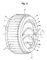
- the cylindrical rollers 4 are disposed between the inner ring raceway surface 2b and the outer ring raceway surface 3b, and are slightly spaced from one another in the circumferential direction (see Fig. 2 ).
- the plurality of oil holes 5 formed in the inner ring 2 are provided at the center part of the inner ring 2 in the axial direction thereof, that is, at the center part of the inner ring raceway surface 2b in the axial direction of the inner ring 2, and extend through the inner ring 2 between this inner ring raceway surface 2b and the inner peripheral face 2c.
- the plurality of oil holes 5 are arranged with a constant interval along the circumferential direction of the inner ring 2.
- the axes of the oil holes 5 extend in the radial direction of the inner ring 2.
- each inclined groove 6 formed on the inner peripheral face 2c of the inner ring 2 has an origin part 6b located at a position corresponding to a position in the axial direction of the inner ring where the oil hole 5 is formed, and extends toward opposite end portions of the inner peripheral face 2c while being inclined relative to the generatrix of the inner peripheral face 2c, thereby forming a V-shaped appearance.
- the origin part 6b is located on a circumferential line on the inner peripheral face 2c at the center part in the axial direction of the inner ring 2.
- the inclined groove 6 has a symmetrical shape in the axial direction of the inner ring 2 relative to the circumferential line (the center line X in the axial direction of the roller bearing 1).
- each inclined groove 6 Distal ends 6a of each inclined groove 6 are located in the vicinity of the opposite ends of the inner peripheral face 2c.
- the inclined grooves 6 are arranged with a constant interval along the inner peripheral face while directing the distal ends 6a to the same direction.
- the number of the inclined grooves 6 is larger than the number of the oil holes 5, so that the oil holes 5 communicate with the origin parts 6b of some of the inclined grooves 6.
- the roller bearing 1 is mounted on the roll R in such a manner that the inclined grooves 6 of the inner ring 2 extend in a forward direction with respect to a rotational direction A of the roll R, that is, the distal ends 6a of the inclined grooves 6 are directed to the rotational direction A of the roll R relative to the origin part 6b.
- the grease is supplied to the area between the inner peripheral face 2c of the inner ring 2 and the journal portion S, and this supplied grease is delivered to the plurality of inclined grooves 6 formed in the inner peripheral face 2c of the inner ring 2, and is guided toward the opposite ends of the inner peripheral face 2c in the axial direction of the inner ring 2. Therefore, the outer peripheral face of the journal portion S and the inner peripheral face 2c of the inner ring 2 can be restrained from being worn by the creep.
- the lubrication grooves in the inner peripheral face 2c of the inner ring 2 are formed by the V-shaped inclined grooves 6, the grease supplied to the area between the journal portion S and the inner peripheral face 2c of the inner ring 2 can be efficiently flowed from the origin parts 6b of the inclined grooves 6 toward the distal ends 6a in accordance with the relative rotation of the journal portion S and the inner ring 2 occurred due to the creep. Namely, at the time of occurrence of the creep when the journal portion S rotates precedingly relative to the inner ring 2, the grease guided into the inclined groove 6 is caused to follow the journal portion S by its viscous resistance, and can be flowed toward the distal ends 6a of the inclined groove 6.
- the grease can be efficiently guided over the entire length from the origin parts 6b of the inclined grooves 6 toward the distal ends 6a. Accordingly, the inner peripheral face 2c of the inner ring 2 can be efficiently lubricated generally over the entire area thereof by this grease.
- axis L of the roll R in the continuous casting installation is deflected by the load, so that larger loads act on an upper portion Y of a left end edge (in Fig. 3 ) of the inner peripheral face 2c of the inner ring 2 and a lower portion Z of a right end edge (lower face side of the journal portion S) disposed 180 degrees out of phase with this upper portion.
- the grease can be efficiently supplied also to the distal ends 6a of the inclined grooves 6, and therefore a good lubrication between each of the left end edge and right end edge of the inner ring inner peripheral face 2c and the journal portion S can be secured.
- a clearance between the inner peripheral face 2c of the inner ring 2 and the outer peripheral face of the journal portion S, a clearance between one end face of the inner ring 2 and the step portion S1 of the journal portion S, and a clearance between the other end face of the inner ring 2 and the fixing member S2 fixed to the journal portion S are shown in an exaggerated manner for better understanding.
- the present invention is not limited to the above embodiment.
- the oil holes 5 are formed in the center part of the inner peripheral face 2c in the axial direction of the inner ring 2.
- they may be formed to be offset from the center part in the axial direction, and the inclined grooves 6 may be formed in an asymmetrical shape accordingly.
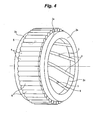
- the invention can be carried out by making various changes such as by using, instead of the V-shaped inclined grooves 6 serving as the lubrication grooves, straight grooves parallel to the generatrix of the inner peripheral face 2c of the inner ring 2 or, as shown in Fig.4 , grooves extending from one end portion to the other end portion of the inner peripheral face 2c of the inner ring 2 while intersecting with the generatrix.
- the above embodiment has illustrated the case where the present invention is applied to the full complement cylindrical roller bearing provided with the aligning housing ring, the invention can be carried out even when it is applied to other roller bearings such as a cylindrical roller bearing provided with a cage, a self-aligning roller bearing and a cylindrical roller bearing with no aligning ring.
- the inclined grooves 6 may be formed only in the inner peripheral face 2c of the inner ring 2 and may not be formed in the inner peripheral face of the loose rib 2e.
Applications Claiming Priority (2)
| Application Number | Priority Date | Filing Date | Title |
|---|---|---|---|
| JP2007207399 | 2007-08-09 | ||
| PCT/JP2008/064345 WO2009020215A1 (ja) | 2007-08-09 | 2008-08-08 | ころ軸受 |
Publications (3)
| Publication Number | Publication Date |
|---|---|
| EP2177777A1 EP2177777A1 (en) | 2010-04-21 |
| EP2177777A4 EP2177777A4 (en) | 2012-05-30 |
| EP2177777B1 true EP2177777B1 (en) | 2013-03-27 |
Family
ID=40341442
Family Applications (1)
| Application Number | Title | Priority Date | Filing Date |
|---|---|---|---|
| EP08826994A Not-in-force EP2177777B1 (en) | 2007-08-09 | 2008-08-08 | Roller bearing |
Country Status (5)
| Country | Link |
|---|---|
| US (1) | US8297849B2 (ja) |
| EP (1) | EP2177777B1 (ja) |
| JP (1) | JP5315847B2 (ja) |
| CN (1) | CN101779049B (ja) |
| WO (1) | WO2009020215A1 (ja) |
Families Citing this family (11)
| Publication number | Priority date | Publication date | Assignee | Title |
|---|---|---|---|---|
| GB0801845D0 (en) * | 2008-02-01 | 2008-03-05 | Cummins Turbo Tech Ltd | A Shaft bearing assembly |
| JP5320281B2 (ja) * | 2009-12-28 | 2013-10-23 | 株式会社ジェイテクト | 転がり軸受 |
| DE102010063391A1 (de) * | 2010-12-17 | 2012-06-21 | Schaeffler Technologies Gmbh & Co. Kg | Lageranordnung für schnelldrehende Wellen von Maschinen |
| CN102518658A (zh) * | 2011-12-22 | 2012-06-27 | 河南三维重工有限公司 | 一种新型辊压机用四列圆柱滚子轴承 |
| US9435380B2 (en) | 2012-10-12 | 2016-09-06 | Jtekt Corporation | Bearing device |
| US8616777B1 (en) * | 2012-11-16 | 2013-12-31 | Pratt & Whitney Canada Corp. | Bearing assembly with inner ring |
| JP6606204B2 (ja) * | 2018-02-01 | 2019-11-13 | 本田技研工業株式会社 | 車両用軸受装置 |
| DE102018203917A1 (de) * | 2018-03-14 | 2019-09-19 | Aktiebolaget Skf | Lageranordnung |
| DE102019117071A1 (de) * | 2019-06-25 | 2020-12-31 | Schaeffler Technologies AG & Co. KG | Ölgeräumte elektrische Maschine mit Wälzlager für ein Kraftfahrzeug |
| DE102020111272A1 (de) * | 2020-04-24 | 2021-10-28 | Conductix-Wampfler Gmbh | Stromschiene für eine Schleifleitung |
| CN116592051B (zh) * | 2023-07-17 | 2023-09-15 | 中达(河北)轴承制造有限公司 | 带座外球面轴承 |
Family Cites Families (25)
| Publication number | Priority date | Publication date | Assignee | Title |
|---|---|---|---|---|
| US3350147A (en) * | 1966-02-01 | 1967-10-31 | Skf Ind Inc | Rolling bearing assembly |
| US4194797A (en) * | 1975-12-12 | 1980-03-25 | Kugelfischer Georg Schafer & Co. | Bearing-race ring with lubricant and cooling channels |
| JPS62147722A (ja) | 1985-12-23 | 1987-07-01 | Hitachi Ltd | エピタキシヤル成長方法 |
| JPS62194241A (ja) | 1986-02-20 | 1987-08-26 | Canon Inc | カメラ用閃光発光装置 |
| JPH0442571Y2 (ja) | 1986-03-12 | 1992-10-08 | ||
| JPH055316Y2 (ja) * | 1986-05-29 | 1993-02-12 | ||
| JPS63157522A (ja) | 1986-12-22 | 1988-06-30 | Yokogawa Electric Corp | 直並列型a/d変換器 |
| JPH064098Y2 (ja) * | 1987-04-01 | 1994-02-02 | 光洋精工株式会社 | 二つ割型回転軸受ユニツト |
| US5125756A (en) * | 1989-12-26 | 1992-06-30 | Lucas Western, Inc. | Roller bearing with load-reacted cage |
| US4974972A (en) * | 1989-12-26 | 1990-12-04 | Lucas Western, Inc. | Crossed roller bearing |
| DE4142802A1 (de) * | 1991-12-23 | 1993-07-01 | Skf Gmbh | Vierreihiges kegelrollenlager |
| FR2711403B1 (fr) * | 1993-10-20 | 1995-11-24 | Skf France | Dispositif d'étanchéité pour passage de fluide à travers un roulement, et roulement équipé d'un tel dispositif. |
| DE29704386U1 (de) * | 1997-03-11 | 1997-04-24 | Skf Gmbh | Vierreihiges Kegelrollenlager, insbesondere für Arbeitswalzen von Walzgerüsten |
| JPH11141555A (ja) * | 1997-11-05 | 1999-05-25 | Nippon Seiko Kk | 油穴付き多列ころ軸受 |
| JPH11257361A (ja) * | 1998-01-08 | 1999-09-21 | Nippon Seiko Kk | 転がり軸受の密封装置 |
| US6428212B1 (en) * | 1999-07-16 | 2002-08-06 | Nsk Ltd. | Lubricating structure of bearing |
| JP2001200855A (ja) * | 2000-01-18 | 2001-07-27 | Nsk Ltd | 転がり軸受 |
| DE10107706A1 (de) * | 2001-02-19 | 2002-10-02 | Rexroth Star Gmbh | Drehlager mit Schmierkanalanordnung Gewindetrieb mit drehgelagerter Gewindemutter |
| JP2002266877A (ja) * | 2001-03-07 | 2002-09-18 | Nsk Ltd | スタータモータ用転がり軸受 |
| US6511228B2 (en) * | 2001-05-08 | 2003-01-28 | Pratt & Whitney Canada Corp. | Oil annulus to circumferentially equalize oil feed to inner race of a bearing |
| JP2004036757A (ja) * | 2002-07-03 | 2004-02-05 | Nsk Ltd | 軸受装置 |
| JP4248973B2 (ja) | 2003-08-29 | 2009-04-02 | Ntn株式会社 | 転がり軸受 |
| DE102005029075B4 (de) | 2005-06-23 | 2007-04-12 | Ab Skf | Anordnung zur Lagerung eines Planetenrades eines Planetengetriebes |
| EP1787830B1 (en) * | 2005-11-17 | 2008-07-23 | Aktiebolaget SKF | A sealing device for bearings having channels for supplying pressurized air to the tire of a vehicle wheel |
| JP2008240778A (ja) * | 2007-03-26 | 2008-10-09 | Nsk Ltd | 自動調心ころ軸受 |
-
2008
- 2008-08-08 US US12/733,123 patent/US8297849B2/en not_active Expired - Fee Related
- 2008-08-08 WO PCT/JP2008/064345 patent/WO2009020215A1/ja active Application Filing
- 2008-08-08 JP JP2008205492A patent/JP5315847B2/ja not_active Expired - Fee Related
- 2008-08-08 EP EP08826994A patent/EP2177777B1/en not_active Not-in-force
- 2008-08-08 CN CN200880102709.5A patent/CN101779049B/zh not_active Expired - Fee Related
Also Published As
| Publication number | Publication date |
|---|---|
| CN101779049A (zh) | 2010-07-14 |
| US8297849B2 (en) | 2012-10-30 |
| JP2009063165A (ja) | 2009-03-26 |
| US20100158422A1 (en) | 2010-06-24 |
| EP2177777A1 (en) | 2010-04-21 |
| EP2177777A4 (en) | 2012-05-30 |
| WO2009020215A1 (ja) | 2009-02-12 |
| CN101779049B (zh) | 2014-02-05 |
| JP5315847B2 (ja) | 2013-10-16 |
Similar Documents
| Publication | Publication Date | Title |
|---|---|---|
| EP2177777B1 (en) | Roller bearing | |
| US8007184B2 (en) | Self-aligning roller bearing with retainer and manufacturing method for self-aligning roller bearing retainer | |
| EP2333368B1 (en) | Rolling bearing | |
| EP3543553B1 (en) | Rolling bearing cage and rolling bearing | |
| JP3039087B2 (ja) | 保持器付自動調心ころ軸受 | |
| JP5286962B2 (ja) | 調心輪付き転がり軸受、及びこれを用いた連続鋳造機用のロール装置 | |
| KR20110003348A (ko) | 경사 롤링 베어링, 특히 2열의 텐덤-볼 롤러 베어링 | |
| CN103140689A (zh) | 滚动轴承 | |
| JPH0828576A (ja) | 保持器付自動調心ころ軸受 | |
| WO2013028284A1 (en) | Bearing cage for a roller bearing assembly | |
| US9291204B2 (en) | Rolling bearing with a lateral filling opening | |
| CN1391043A (zh) | 一种安装装置 | |
| EP2703665B1 (en) | Outer double-row ball bearing assembly combined with inner plain bearing | |
| JP2006112555A (ja) | 調心輪付きころ軸受 | |
| JP2012021624A (ja) | 自動調心ころ軸受及び給油構造付自動調心ころ軸受 | |
| JP5987290B2 (ja) | 軸受装置 | |
| EP2202418B1 (en) | Rolling bearing | |
| CN202326717U (zh) | 一种内、外组件均为圆柱滚子的三环轴承 | |
| US20120039557A1 (en) | Rolling bearing with spherical separators | |
| JP2018168871A (ja) | フォロア軸受 | |
| JP2009180235A (ja) | 自動調心ころ軸受 | |
| JP3551031B2 (ja) | 軸受潤滑構造 | |
| CN116164034A (zh) | 滚动轴承,特别是大直径滚动轴承 | |
| KR101398984B1 (ko) | 롤러 및 이를 이용한 롤러 베어링 | |
| JP2009168106A (ja) | ころ軸受及びころ軸受の固定構造 |
Legal Events
| Date | Code | Title | Description |
|---|---|---|---|
| PUAI | Public reference made under article 153(3) epc to a published international application that has entered the european phase |
Free format text: ORIGINAL CODE: 0009012 |
|
| 17P | Request for examination filed |
Effective date: 20100208 |
|
| AK | Designated contracting states |
Kind code of ref document: A1 Designated state(s): AT BE BG CH CY CZ DE DK EE ES FI FR GB GR HR HU IE IS IT LI LT LU LV MC MT NL NO PL PT RO SE SI SK TR |
|
| AX | Request for extension of the european patent |
Extension state: AL BA MK RS |
|
| DAX | Request for extension of the european patent (deleted) | ||
| A4 | Supplementary search report drawn up and despatched |
Effective date: 20120427 |
|
| RIC1 | Information provided on ipc code assigned before grant |
Ipc: F16C 33/58 20060101ALI20120423BHEP Ipc: F16C 19/26 20060101ALI20120423BHEP Ipc: F16C 33/66 20060101AFI20120423BHEP |
|
| GRAP | Despatch of communication of intention to grant a patent |
Free format text: ORIGINAL CODE: EPIDOSNIGR1 |
|
| GRAS | Grant fee paid |
Free format text: ORIGINAL CODE: EPIDOSNIGR3 |
|
| GRAA | (expected) grant |
Free format text: ORIGINAL CODE: 0009210 |
|
| AK | Designated contracting states |
Kind code of ref document: B1 Designated state(s): AT BE BG CH CY CZ DE DK EE ES FI FR GB GR HR HU IE IS IT LI LT LU LV MC MT NL NO PL PT RO SE SI SK TR |
|
| REG | Reference to a national code |
Ref country code: GB Ref legal event code: FG4D |
|
| REG | Reference to a national code |
Ref country code: CH Ref legal event code: EP |
|
| REG | Reference to a national code |
Ref country code: AT Ref legal event code: REF Ref document number: 603587 Country of ref document: AT Kind code of ref document: T Effective date: 20130415 |
|
| REG | Reference to a national code |
Ref country code: IE Ref legal event code: FG4D |
|
| REG | Reference to a national code |
Ref country code: DE Ref legal event code: R096 Ref document number: 602008023314 Country of ref document: DE Effective date: 20130523 |
|
| PG25 | Lapsed in a contracting state [announced via postgrant information from national office to epo] |
Ref country code: BG Free format text: LAPSE BECAUSE OF FAILURE TO SUBMIT A TRANSLATION OF THE DESCRIPTION OR TO PAY THE FEE WITHIN THE PRESCRIBED TIME-LIMIT Effective date: 20130627 Ref country code: NO Free format text: LAPSE BECAUSE OF FAILURE TO SUBMIT A TRANSLATION OF THE DESCRIPTION OR TO PAY THE FEE WITHIN THE PRESCRIBED TIME-LIMIT Effective date: 20130627 Ref country code: LT Free format text: LAPSE BECAUSE OF FAILURE TO SUBMIT A TRANSLATION OF THE DESCRIPTION OR TO PAY THE FEE WITHIN THE PRESCRIBED TIME-LIMIT Effective date: 20130327 Ref country code: SE Free format text: LAPSE BECAUSE OF FAILURE TO SUBMIT A TRANSLATION OF THE DESCRIPTION OR TO PAY THE FEE WITHIN THE PRESCRIBED TIME-LIMIT Effective date: 20130327 |
|
| REG | Reference to a national code |
Ref country code: AT Ref legal event code: MK05 Ref document number: 603587 Country of ref document: AT Kind code of ref document: T Effective date: 20130327 |
|
| REG | Reference to a national code |
Ref country code: LT Ref legal event code: MG4D |
|
| PG25 | Lapsed in a contracting state [announced via postgrant information from national office to epo] |
Ref country code: GR Free format text: LAPSE BECAUSE OF FAILURE TO SUBMIT A TRANSLATION OF THE DESCRIPTION OR TO PAY THE FEE WITHIN THE PRESCRIBED TIME-LIMIT Effective date: 20130628 Ref country code: SI Free format text: LAPSE BECAUSE OF FAILURE TO SUBMIT A TRANSLATION OF THE DESCRIPTION OR TO PAY THE FEE WITHIN THE PRESCRIBED TIME-LIMIT Effective date: 20130327 Ref country code: LV Free format text: LAPSE BECAUSE OF FAILURE TO SUBMIT A TRANSLATION OF THE DESCRIPTION OR TO PAY THE FEE WITHIN THE PRESCRIBED TIME-LIMIT Effective date: 20130327 Ref country code: FI Free format text: LAPSE BECAUSE OF FAILURE TO SUBMIT A TRANSLATION OF THE DESCRIPTION OR TO PAY THE FEE WITHIN THE PRESCRIBED TIME-LIMIT Effective date: 20130327 |
|
| REG | Reference to a national code |
Ref country code: NL Ref legal event code: VDEP Effective date: 20130327 |
|
| PG25 | Lapsed in a contracting state [announced via postgrant information from national office to epo] |
Ref country code: BE Free format text: LAPSE BECAUSE OF FAILURE TO SUBMIT A TRANSLATION OF THE DESCRIPTION OR TO PAY THE FEE WITHIN THE PRESCRIBED TIME-LIMIT Effective date: 20130327 Ref country code: HR Free format text: LAPSE BECAUSE OF FAILURE TO SUBMIT A TRANSLATION OF THE DESCRIPTION OR TO PAY THE FEE WITHIN THE PRESCRIBED TIME-LIMIT Effective date: 20130327 |
|
| PG25 | Lapsed in a contracting state [announced via postgrant information from national office to epo] |
Ref country code: ES Free format text: LAPSE BECAUSE OF FAILURE TO SUBMIT A TRANSLATION OF THE DESCRIPTION OR TO PAY THE FEE WITHIN THE PRESCRIBED TIME-LIMIT Effective date: 20130708 Ref country code: EE Free format text: LAPSE BECAUSE OF FAILURE TO SUBMIT A TRANSLATION OF THE DESCRIPTION OR TO PAY THE FEE WITHIN THE PRESCRIBED TIME-LIMIT Effective date: 20130327 Ref country code: NL Free format text: LAPSE BECAUSE OF FAILURE TO SUBMIT A TRANSLATION OF THE DESCRIPTION OR TO PAY THE FEE WITHIN THE PRESCRIBED TIME-LIMIT Effective date: 20130327 Ref country code: SK Free format text: LAPSE BECAUSE OF FAILURE TO SUBMIT A TRANSLATION OF THE DESCRIPTION OR TO PAY THE FEE WITHIN THE PRESCRIBED TIME-LIMIT Effective date: 20130327 Ref country code: PT Free format text: LAPSE BECAUSE OF FAILURE TO SUBMIT A TRANSLATION OF THE DESCRIPTION OR TO PAY THE FEE WITHIN THE PRESCRIBED TIME-LIMIT Effective date: 20130729 Ref country code: AT Free format text: LAPSE BECAUSE OF FAILURE TO SUBMIT A TRANSLATION OF THE DESCRIPTION OR TO PAY THE FEE WITHIN THE PRESCRIBED TIME-LIMIT Effective date: 20130327 Ref country code: CZ Free format text: LAPSE BECAUSE OF FAILURE TO SUBMIT A TRANSLATION OF THE DESCRIPTION OR TO PAY THE FEE WITHIN THE PRESCRIBED TIME-LIMIT Effective date: 20130327 Ref country code: IS Free format text: LAPSE BECAUSE OF FAILURE TO SUBMIT A TRANSLATION OF THE DESCRIPTION OR TO PAY THE FEE WITHIN THE PRESCRIBED TIME-LIMIT Effective date: 20130727 Ref country code: RO Free format text: LAPSE BECAUSE OF FAILURE TO SUBMIT A TRANSLATION OF THE DESCRIPTION OR TO PAY THE FEE WITHIN THE PRESCRIBED TIME-LIMIT Effective date: 20130327 |
|
| PG25 | Lapsed in a contracting state [announced via postgrant information from national office to epo] |
Ref country code: CY Free format text: LAPSE BECAUSE OF FAILURE TO SUBMIT A TRANSLATION OF THE DESCRIPTION OR TO PAY THE FEE WITHIN THE PRESCRIBED TIME-LIMIT Effective date: 20130327 Ref country code: PL Free format text: LAPSE BECAUSE OF FAILURE TO SUBMIT A TRANSLATION OF THE DESCRIPTION OR TO PAY THE FEE WITHIN THE PRESCRIBED TIME-LIMIT Effective date: 20130327 |
|
| PG25 | Lapsed in a contracting state [announced via postgrant information from national office to epo] |
Ref country code: DK Free format text: LAPSE BECAUSE OF FAILURE TO SUBMIT A TRANSLATION OF THE DESCRIPTION OR TO PAY THE FEE WITHIN THE PRESCRIBED TIME-LIMIT Effective date: 20130327 |
|
| PLBE | No opposition filed within time limit |
Free format text: ORIGINAL CODE: 0009261 |
|
| STAA | Information on the status of an ep patent application or granted ep patent |
Free format text: STATUS: NO OPPOSITION FILED WITHIN TIME LIMIT |
|
| PG25 | Lapsed in a contracting state [announced via postgrant information from national office to epo] |
Ref country code: IT Free format text: LAPSE BECAUSE OF FAILURE TO SUBMIT A TRANSLATION OF THE DESCRIPTION OR TO PAY THE FEE WITHIN THE PRESCRIBED TIME-LIMIT Effective date: 20130327 |
|
| 26N | No opposition filed |
Effective date: 20140103 |
|
| REG | Reference to a national code |
Ref country code: CH Ref legal event code: PL |
|
| REG | Reference to a national code |
Ref country code: DE Ref legal event code: R097 Ref document number: 602008023314 Country of ref document: DE Effective date: 20140103 |
|
| GBPC | Gb: european patent ceased through non-payment of renewal fee |
Effective date: 20130808 |
|
| PG25 | Lapsed in a contracting state [announced via postgrant information from national office to epo] |
Ref country code: MC Free format text: LAPSE BECAUSE OF FAILURE TO SUBMIT A TRANSLATION OF THE DESCRIPTION OR TO PAY THE FEE WITHIN THE PRESCRIBED TIME-LIMIT Effective date: 20130327 Ref country code: CH Free format text: LAPSE BECAUSE OF NON-PAYMENT OF DUE FEES Effective date: 20130831 Ref country code: LI Free format text: LAPSE BECAUSE OF NON-PAYMENT OF DUE FEES Effective date: 20130831 |
|
| REG | Reference to a national code |
Ref country code: IE Ref legal event code: MM4A |
|
| PG25 | Lapsed in a contracting state [announced via postgrant information from national office to epo] |
Ref country code: IE Free format text: LAPSE BECAUSE OF NON-PAYMENT OF DUE FEES Effective date: 20130808 Ref country code: GB Free format text: LAPSE BECAUSE OF NON-PAYMENT OF DUE FEES Effective date: 20130808 |
|
| REG | Reference to a national code |
Ref country code: FR Ref legal event code: PLFP Year of fee payment: 8 |
|
| PG25 | Lapsed in a contracting state [announced via postgrant information from national office to epo] |
Ref country code: TR Free format text: LAPSE BECAUSE OF FAILURE TO SUBMIT A TRANSLATION OF THE DESCRIPTION OR TO PAY THE FEE WITHIN THE PRESCRIBED TIME-LIMIT Effective date: 20130327 Ref country code: MT Free format text: LAPSE BECAUSE OF FAILURE TO SUBMIT A TRANSLATION OF THE DESCRIPTION OR TO PAY THE FEE WITHIN THE PRESCRIBED TIME-LIMIT Effective date: 20130327 |
|
| PG25 | Lapsed in a contracting state [announced via postgrant information from national office to epo] |
Ref country code: HU Free format text: LAPSE BECAUSE OF FAILURE TO SUBMIT A TRANSLATION OF THE DESCRIPTION OR TO PAY THE FEE WITHIN THE PRESCRIBED TIME-LIMIT; INVALID AB INITIO Effective date: 20080808 Ref country code: LU Free format text: LAPSE BECAUSE OF NON-PAYMENT OF DUE FEES Effective date: 20130808 |
|
| PGFP | Annual fee paid to national office [announced via postgrant information from national office to epo] |
Ref country code: FR Payment date: 20150629 Year of fee payment: 8 |
|
| REG | Reference to a national code |
Ref country code: FR Ref legal event code: ST Effective date: 20170428 |
|
| PG25 | Lapsed in a contracting state [announced via postgrant information from national office to epo] |
Ref country code: FR Free format text: LAPSE BECAUSE OF NON-PAYMENT OF DUE FEES Effective date: 20160831 |
|
| PGFP | Annual fee paid to national office [announced via postgrant information from national office to epo] |
Ref country code: DE Payment date: 20200729 Year of fee payment: 13 |
|
| REG | Reference to a national code |
Ref country code: DE Ref legal event code: R119 Ref document number: 602008023314 Country of ref document: DE |
|
| PG25 | Lapsed in a contracting state [announced via postgrant information from national office to epo] |
Ref country code: DE Free format text: LAPSE BECAUSE OF NON-PAYMENT OF DUE FEES Effective date: 20220301 |