EP2176566B2 - Kraftübertragungseinrichtung umfassend eine hydrodynamische Komponente und eine Überbrückungskupplung sowie eine Vorrichtung zur Dämpfung von Schwingungen - Google Patents
Kraftübertragungseinrichtung umfassend eine hydrodynamische Komponente und eine Überbrückungskupplung sowie eine Vorrichtung zur Dämpfung von Schwingungen Download PDFInfo
- Publication number
- EP2176566B2 EP2176566B2 EP08801063.2A EP08801063A EP2176566B2 EP 2176566 B2 EP2176566 B2 EP 2176566B2 EP 08801063 A EP08801063 A EP 08801063A EP 2176566 B2 EP2176566 B2 EP 2176566B2
- Authority
- EP
- European Patent Office
- Prior art keywords
- damper
- power transmission
- damper arrangement
- transmission means
- means according
- Prior art date
- Legal status (The legal status is an assumption and is not a legal conclusion. Google has not performed a legal analysis and makes no representation as to the accuracy of the status listed.)
- Not-in-force
Links
- 230000005540 biological transmission Effects 0.000 title claims description 53
- 238000013016 damping Methods 0.000 title claims description 50
- 230000008878 coupling Effects 0.000 claims description 31
- 238000010168 coupling process Methods 0.000 claims description 31
- 238000005859 coupling reaction Methods 0.000 claims description 31
- 230000000712 assembly Effects 0.000 description 15
- 238000000429 assembly Methods 0.000 description 15
- 230000006835 compression Effects 0.000 description 3
- 238000007906 compression Methods 0.000 description 3
- 238000004519 manufacturing process Methods 0.000 description 3
- 239000006096 absorbing agent Substances 0.000 description 2
- 238000010586 diagram Methods 0.000 description 2
- 238000009434 installation Methods 0.000 description 2
- 230000010354 integration Effects 0.000 description 2
- 230000015572 biosynthetic process Effects 0.000 description 1
- 230000001419 dependent effect Effects 0.000 description 1
- 230000000694 effects Effects 0.000 description 1
- 238000013017 mechanical damping Methods 0.000 description 1
- 230000007935 neutral effect Effects 0.000 description 1
- 230000035939 shock Effects 0.000 description 1
- 210000002105 tongue Anatomy 0.000 description 1
Images


Classifications
-
- F—MECHANICAL ENGINEERING; LIGHTING; HEATING; WEAPONS; BLASTING
- F16—ENGINEERING ELEMENTS AND UNITS; GENERAL MEASURES FOR PRODUCING AND MAINTAINING EFFECTIVE FUNCTIONING OF MACHINES OR INSTALLATIONS; THERMAL INSULATION IN GENERAL
- F16H—GEARING
- F16H45/00—Combinations of fluid gearings for conveying rotary motion with couplings or clutches
- F16H45/02—Combinations of fluid gearings for conveying rotary motion with couplings or clutches with mechanical clutches for bridging a fluid gearing of the hydrokinetic type
-
- F—MECHANICAL ENGINEERING; LIGHTING; HEATING; WEAPONS; BLASTING
- F16—ENGINEERING ELEMENTS AND UNITS; GENERAL MEASURES FOR PRODUCING AND MAINTAINING EFFECTIVE FUNCTIONING OF MACHINES OR INSTALLATIONS; THERMAL INSULATION IN GENERAL
- F16F—SPRINGS; SHOCK-ABSORBERS; MEANS FOR DAMPING VIBRATION
- F16F15/00—Suppression of vibrations in systems; Means or arrangements for avoiding or reducing out-of-balance forces, e.g. due to motion
- F16F15/10—Suppression of vibrations in rotating systems by making use of members moving with the system
- F16F15/12—Suppression of vibrations in rotating systems by making use of members moving with the system using elastic members or friction-damping members, e.g. between a rotating shaft and a gyratory mass mounted thereon
- F16F15/121—Suppression of vibrations in rotating systems by making use of members moving with the system using elastic members or friction-damping members, e.g. between a rotating shaft and a gyratory mass mounted thereon using springs as elastic members, e.g. metallic springs
- F16F15/123—Wound springs
- F16F15/12353—Combinations of dampers, e.g. with multiple plates, multiple spring sets, i.e. complex configurations
- F16F15/1236—Combinations of dampers, e.g. with multiple plates, multiple spring sets, i.e. complex configurations resulting in a staged spring characteristic, e.g. with multiple intermediate plates
- F16F15/12366—Combinations of dampers, e.g. with multiple plates, multiple spring sets, i.e. complex configurations resulting in a staged spring characteristic, e.g. with multiple intermediate plates acting on multiple sets of springs
-
- F—MECHANICAL ENGINEERING; LIGHTING; HEATING; WEAPONS; BLASTING
- F16—ENGINEERING ELEMENTS AND UNITS; GENERAL MEASURES FOR PRODUCING AND MAINTAINING EFFECTIVE FUNCTIONING OF MACHINES OR INSTALLATIONS; THERMAL INSULATION IN GENERAL
- F16H—GEARING
- F16H45/00—Combinations of fluid gearings for conveying rotary motion with couplings or clutches
- F16H45/02—Combinations of fluid gearings for conveying rotary motion with couplings or clutches with mechanical clutches for bridging a fluid gearing of the hydrokinetic type
- F16H2045/0221—Combinations of fluid gearings for conveying rotary motion with couplings or clutches with mechanical clutches for bridging a fluid gearing of the hydrokinetic type with damping means
- F16H2045/0226—Combinations of fluid gearings for conveying rotary motion with couplings or clutches with mechanical clutches for bridging a fluid gearing of the hydrokinetic type with damping means comprising two or more vibration dampers
- F16H2045/0231—Combinations of fluid gearings for conveying rotary motion with couplings or clutches with mechanical clutches for bridging a fluid gearing of the hydrokinetic type with damping means comprising two or more vibration dampers arranged in series
-
- F—MECHANICAL ENGINEERING; LIGHTING; HEATING; WEAPONS; BLASTING
- F16—ENGINEERING ELEMENTS AND UNITS; GENERAL MEASURES FOR PRODUCING AND MAINTAINING EFFECTIVE FUNCTIONING OF MACHINES OR INSTALLATIONS; THERMAL INSULATION IN GENERAL
- F16H—GEARING
- F16H45/00—Combinations of fluid gearings for conveying rotary motion with couplings or clutches
- F16H45/02—Combinations of fluid gearings for conveying rotary motion with couplings or clutches with mechanical clutches for bridging a fluid gearing of the hydrokinetic type
- F16H2045/0221—Combinations of fluid gearings for conveying rotary motion with couplings or clutches with mechanical clutches for bridging a fluid gearing of the hydrokinetic type with damping means
- F16H2045/0247—Combinations of fluid gearings for conveying rotary motion with couplings or clutches with mechanical clutches for bridging a fluid gearing of the hydrokinetic type with damping means having a turbine with hydrodynamic damping means
Definitions
- the invention relates to a power transmission device comprising a device for damping vibrations, in particular a multi-stage torsional vibration damper, comprising at least two coaxially arranged damper arrangements connected in parallel, a first damper arrangement and a second damper arrangement.
- Mechanical dampers include a one-part or multi-part rotary part that functions as an input part or output part of the device for damping vibrations, depending on the direction of force flow, in particular a primary part and a secondary part, which are arranged coaxially with one another and can be rotated relative to one another to a limited extent in the circumferential direction.
- the coupling between the input part and the output part takes place via means for torque transmission and means for damping vibrations, which are generally formed by spring units comprising at least one spring element in the form of a compression spring.
- the vibrations can be compensated and reduced via the size of the torsion angle between the input part and output part and the spring force.
- a device for damping vibrations comprising at least two damper arrangements, which are connected in parallel, is already known, with both damper arrangements always being effective.
- the damper arrangement for the smaller torsion angles is arranged here on a radially inner diameter, while the larger torsional play is realized via the second damper arrangement on a radially outer diameter.
- the radially inner damper arrangement is designed as a series damper, comprising spring elements that are separated by a flange and connected in series.
- a device designed as a series-parallel damper for damping vibrations comprising a first rotating element and a second rotating element, which can be rotated relative to one another to a limited extent in the circumferential direction.
- the device comprises a pair of first elastic members aligned in a direction of rotation and connected in series, coupled via an intermediate floating flange, and another second elastic member connected in parallel to the first elastic members, the second elastic member is configured to be compressed in the rotation direction after the pair of first elastic members is compressed to a first angle due to relative rotation of the first rotation member and the second rotation member.
- a clearance angle which is integrated in the floating flange, is assigned to the second elastic element.
- the arrangement of the first and second elastic elements takes place to reduce the radial installation space on a diameter or in the radial direction with regard to the theoretically resulting ring-shaped areas resulting from the extension of the spring elements overlapping one another.
- the coupling between the first elastic elements takes place via a floating flange.
- the U.S. 2007/0051577 A1 a damper assembly for damping torque output from a turbine of a torque converter to a transmission.
- a first (single) damper in series with a parallel connection of two dampers between a cover plate and an output flange.
- the JP-A-10047453 finally shows a generic power transmission device.
- the invention is therefore based on the object of creating a power transmission device comprising a device for damping vibrations with a low spring rate at low torques, the device for damping vibrations being characterized by a relatively flat characteristic curve.
- This map range which can be interpreted for the transmission of a part of the theoretically maximum possible torque, should be describable by the largest possible range of torsion angles between the rotary elements functioning as input and output parts.
- the solution according to the invention should be characterized by low design and manufacturing complexity and also be suitable for integration in power transmission devices for use in drive trains, the device for damping vibrations should be as small as possible in the radial and axial direction.
- a device for damping vibrations in particular a multi-stage series-parallel torsional vibration damper, comprises at least two parallel-connected and coaxially arranged damper assemblies and having at least one input and one output part, a first damper assembly and a second damper assembly having torsional backlash, one of the damper assemblies being Series damper, comprising two individual dampers connected at least in series and coupled via an intermediate flange.
- the first damper arrangement is arranged on a diameter in the radial direction that is larger than the diameter of the arrangement of the second damper arrangement.
- the output part of the first damper arrangement and the output part of the second damper arrangement form a structural unit.
- the solution according to the invention makes it possible on the one hand to create a very compact combined damping arrangement in which the vibration damper is characterized by the lowest possible spring rate in the largest possible torsion angle range with low friction. Due to the concentration of functions in individual components, production is relatively simple and associated with low costs.
- the second damper arrangement is arranged as close as possible to the axis of rotation.
- Both damper assemblies are arranged coaxially to one another and can be arranged with an offset in the axial direction or preferably in one plane.
- the damper arrangement in the form of the multi-stage damper in which the damper characteristic can be variably adjusted due to the separate configuration of the individual damper arrangement, is relatively small in the axial direction and also in the radial direction.
- the first damper arrangement comprises at least two dampers connected in series, a first and a second damper, with the output part of one damper forming the input part of the other damper or being non-rotatably coupled to it.
- the series damper is realized on a common diameter, that is, the two individual dampers are arranged on a common diameter and are not offset in the radial direction. In this case, the radial dimensions for the entire damper can be kept small.
- each of the individual dampers of a series damper arrangement preferably has identically dimensioned means for torque transmission and/or means for damping coupling. This makes it possible, with appropriate integration in the overall system, to also realize an independence of the direction of twisting angle and in any case to conduct the torque via the output of the first damper arrangement in combination with the torque transmitted via the second damper arrangement to an element to be driven in a drive train.
- the individual dampers of the first damper arrangement can theoretically also be designed differently.
- the individual dampers of the first damper arrangement designed as a series damper are coupled to one another via an intermediate flange which, depending on the connection, can be designed as a drive plate or as a floating flange.
- this is designed as an annular element with stop surfaces for the means for torque transmission and damping coupling forming projections pointing in the radial direction on the inner circumference in the direction of the axis of rotation and aligned in the circumferential direction.
- Another flange lying radially within the extent of the intermediate flange which is designed as an annular element with projections aligned in the radial direction on the outer circumference. Depending on the connection, this acts as an input or output part for the second damper arrangement.
- the torsional backlash of the second damper assembly is characterized by a predefined torsion angle, describing a clearance angle, between the input part and the output part of the second damper assembly, in which the second damper assembly is not effective.
- the torsion angle is integrated in the output part.
- each of the individual damper arrangements comprises a primary part functioning as an input part and a secondary part functioning as an output part.
- the function depends on the direction of power flow and changing them interchangeably, i.e. changing.
- the input and output parts can be made in one piece or in several pieces.
- One-piece disc-shaped designs are preferably selected in each case.
- These are coupled to one another via the means for torque transmission and means for damping coupling.
- the means for torque transmission and damping coupling are formed by elastic elements, in particular spring units.
- the individual spring units are designed as individual springs or can also be in the form of spring units connected in series.
- the individual damper arrangement acts as an elastic coupling that transmits torque and at the same time compensates for vibrations.
- the first damper assembly includes at least both an input portion and an output portion.
- the input and output parts of the individual damper assemblies form a structural unit, i.e. they can be coupled to one another in a torque-proof manner, for example.
- the individual input and output parts are designed as separate elements that are functionally coupled to one another only via the connection.
- an integral design is sought, i.e. the input part and output part of the first and second damper arrangement are each designed in one piece, i.e. the elements of the first damper arrangement forming the input part or output part are simultaneously the input part or output part of the second damper arrangement executed.
- the device is designed as a mechanical friction damper.
- this comprises at least two side disks which are arranged in the axial direction and coupled to one another in a torque-proof manner and which can function as driver disks or as an output part.
- the side windows include openings formed in the circumferential direction for receiving and forming stop surfaces formed opposite to one another for the spring elements of the individual damper assemblies and the dampers of the first damper assembly.
- the recesses or through openings forming stop surfaces in the circumferential direction are arranged relative to one another in such a way that a clearance angle, i.e. a torsion range between the input and output parts, can be realized for the second damper arrangement, which has no effect whatsoever with regard to the second damper device, i.e. the second Damper device only becomes effective when a certain predefined angle of rotation between the input part and output part is achieved.
- this statement also applies to the flange arranged between the two side windows, in particular the disk-shaped element in the form of the flange, which at the same time forms the output part of the first and second damper arrangement.
- the different elements can each function as an input part. This depends on which of the elements are coupled to the drive arrangement and which are viewed with the output side in the direction of power flow.
- the drive can be implemented via side windows. In this case, they are at least indirectly coupled in a rotationally fixed manner to a driving element, for example in a power transmission device of a lock-up clutch or a drive machine. The power is then transmitted in the first damper arrangement to the intermediate flange and from there to the flange which forms the output part of the device and the output part of the second damper arrangement.
- the power is transmitted to the side windows of the first and second damper assemblies, which act as an output part.
- the Figure 1a clarifies in a simplified schematic representation the basic structure and the basic principle of a device 1 designed according to the invention for damping vibrations, in particular in the form of a torsional vibration damper or torsional vibration damper.
- the device 1 according to the invention for damping vibrations is designed as a multi-stage series-parallel damper 2 .
- the device 1 for damping vibrations functionally comprises two damper stages 3, 4, each of which is formed by a damper arrangement—a first damper arrangement 5 and a second damper arrangement 7—and are connected in parallel. Connected in parallel means that both damper assemblies 5 and 7 are arranged in parallel in the power flow. The power flow takes place in parallel or via both damper assemblies 5 and 7.
- the first damper assembly 5 is designed according to the invention as a series damper, that is, it comprises at least two series-connected dampers 6.1 and 6.2. Connected in series means that the power transmission in the power flow takes place in series, in particular both dampers 6.1 and 6.2 in damper stage 3 are run through one after the other, with the direction being determined as a function of the direction in which the force is introduced. In figure 1 a, the power flow takes place, for example, via the damper 6.1 and 6.2.
- each of the damper stages 3 and 4 is effective in different operating ranges.
- the damper arrangement 7 of the second damper stage 4 is designed in such a way that it only becomes effective after a predefined twisting angle F, which is also referred to as the clearance angle.
- Both damper assemblies 5 and 7 are arranged in parallel and combined to form the two-stage series-parallel damper.
- Each of the individual damper assemblies 5 and 7 comprises rotating elements which are designed in one or more parts and, viewed in the direction of force flow, act as input parts and output parts, which are coupled to one another via means for torque transmission and/or means for damping coupling.
- the means for torque transmission and the means for damping coupling are preferably formed by the same structural units, preferably by spring units.
- the input and output parts of the individual damper assemblies 5, 7 and the individual dampers 6.1, 6.2 of the damper assembly 5 are each arranged coaxially with one another and can be rotated in relation to one another to a limited extent in the circumferential direction.
- the term input and output part refers to the power flow when arranged in a drive train from a driving to a driven component.
- the functions as an input and output part can be assigned to different components in different operating states, i.e. when used in vehicles in drive trains in traction mode, elements that can be coupled to a drive machine act as an input part, while the function is reversed in overrun mode by the element that functions as an output part in traction mode now functions as an input part.
- the device 1 comprises an input part E and an output part A viewed in the power flow.
- the input part E is formed by an element of the damper assembly 5 and the damper assembly 7 as a structural unit, or the input parts of the damper assemblies 5 and 7 are connected to one another in a torque-proof manner.
- the damper assembly 5 includes an input part 8 and an output part 10.
- the damper assembly 7 includes an input part 11 and an output part 12.
- the input parts 8 and 11 are preferably formed directly from the input part E and the output parts 10, 12 from the output part A.
- In the first Damper assembly 5 are two dampers connected in series, the damper 6.1 and the damper 6.2.
- the input 8 of the first damper arrangement which is non-rotatably connected to the input E of the overall unit or is preferably formed directly by this, is formed by the input part 13 of the first damper 6.1.
- the first damper 6.1 also includes an output part 14, which at the same time forms the input part 15 of the second damper 6.2 of the two series-connected dampers of the damper arrangement 5 or is connected to it in a rotationally fixed manner.
- the second damper 6.2 also includes an output part 16, which forms the output part 10 of the damper assembly 5 and which is connected to the output A in a torque-proof manner or forms it.
- the first damper 6.1 includes means 17 for torque transmission between the input part 13 and the output part 14 and means 18 for damping coupling.
- the second damper 6.2 includes means 20 for torque transmission and means 21 for damping coupling.
- the second damper arrangement 7 comprises at least one damper, in which the input part 11 and the output part 12 are coupled to one another via means 34 for torque transmission and means 35 for damping coupling.
- the power flow takes place between the input part E and the output part A of the device depending on the direction of rotation in the first damping arrangement 5 via the damper 6.1 and the damper 6.2 or vice versa and at the same time after reaching the predefined angle of rotation between the input part E and the output part A the damper arrangement 7.
- the second damper arrangement 7 does not become effective immediately when a twisting angle occurs between the input and output parts E, A, but only after a certain twisting angle has been reached between the input part E and the output part A. This angle is also known as a clearance angle designated. If this is reached, the second damper stage 4, which is formed by the second damper arrangement 7, is switched on.
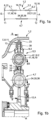
- the figures 1b and 1c illustrate a device designed according to the invention for damping vibrations 1, in particular a multi-stage series-parallel damper arrangement 2 in two views.
- the Figure 1b clarified the device 1 for damping vibrations in axial section
- the Figure 1c shows a view B - B from the right.
- the arrangement of the flanges 23, 24 is shown in the neutral position, ie free of torque.
- the first damper stage 3 is arranged in the radial direction relative to the axis of rotation R of the device 1 on a larger diameter d 3 than the second further damper stage 4 on d 4 .
- the first damper arrangement 5 is thus arranged radially on the outside, while the second damper arrangement 7 is arranged within the extension of the inner diameter of the first damper arrangement 5 and thus at a smaller diameter d 4 .
- the input part E of the device 1 and thus the input parts 8, 10 of the damper assemblies 5, 7 are formed by two mutually spaced apart and coaxial driver disks 9.1 and 9.2, which are non-rotatably coupled to one another.
- the output part 10 is arranged between the driver disks 9.1 and 9.2 and is non-rotatably connected to the output part 12 of the damper arrangement 7 or preferably forms a structural unit in the form of one component and at the same time forms the output A with it.
- the first damper assembly 5 consists of the two dampers 6.1 and 6.2. The numbering of the input and output parts according to Figure 1a will be maintained.
- the input part 13 of the first damper 6.1 is formed by the driver disks 9.1 and 9.2. This also applies analogously to the input part 11 of the second damper arrangement 7, the input part 11 here also being formed by the driver disks 9.1 and 9.2 or with these elements coupled in a torque-proof manner.
- the first damper comprises means 17 for torque transmission between the input part 13 and the output part 14 and means 18 for damping coupling, with the means 17 and the means 18 being formed by a structural unit, in particular a spring unit 19, comprising at least one spring element in the form of a compression spring .
- the second damper 6.2 also includes means 20 for torque transmission and means 21 for damping coupling, these being formed by a further spring unit 22.
- the input part 13 is formed by the drive disks 9.1 and 9.2, the output part 14 by a so-called floating intermediate flange 23, which does not have its own bearing or non-rotatable connection to a connecting element.
- the intermediate flange 23 forms the input part 15 of the second damper 6.2.
- the output part 16 of the second damper 6.2 and thus the output part 10 or A of the device 1 is formed by a flange 24.
- the means 17 and 18 or the individual spring units 19 of the first damper 6.1 are supported in the driver disks 9.1 and 9.2, the flange 24 or the intermediate flange 23, while the spring units 22 of the second damper 6.2 are also supported on the driver disks 9.1, 9.2 or the Intermediate flange 23 and the flange 24 can support in the circumferential direction.
- the intermediate flange 23 is designed as a floating flange, i.e. it does not have its own bearing and is only held between the spring units 19, 22 by the spring units 19, 22 and the arrangement of the flange 24 or the side windows 9.1 and 9.2.
- the intermediate flange 23 is designed as an annular element, which has projections 25 on its inner circumference pointing in the direction of the axis of rotation R, which form stop surfaces 26 and 27 for the spring units 19 and 22 of the dampers 6.1 and 6.2, which are aligned in the circumferential direction and directed opposite to one another.
- the flange 24 here forms the output part 10, 12 of both the first and the second damper arrangement 5, 7 and thus also the output part A of the entire device 1 for damping vibrations. This is designed as a disc-shaped element.
- the intermediate flange 23 is an outer intermediate flange in the radial direction, which has the projections on its inner circumference 28, which are spaced apart uniformly in the circumferential direction.
- the flange 24, which forms the output part 10 or 12 of the damper assemblies 5, 7, is designed as a radially inner flange and points on its outer circumference 29 in the radial direction outwards, i.e.
- the flange 24 also includes recesses 33 on its diameter d 4 in the form of openings extending in the circumferential direction, which form support surfaces 37.1, 37.2 for the spring units 36 of the means 34 for torque transmission and 35 for damping coupling, respectively.
- the support surfaces 37.1, 37.2 are arranged opposite one another in the circumferential direction. However, these support surfaces 37.1, 37.2 only become effective after a certain angle of rotation F, which is between 3 and 50°, for example.
- the spring units 36 are supported on the side windows 9.1 and 9.2 and the flange 24.
- a torque is introduced into the damper assembly 5 via the driver disks 9.1 and 9.2, which are coupled to one another in a rotationally fixed manner, with Figure 1c depending on the direction of rotation, the spring units 19 or 22 are acted upon, which in turn act on the intermediate flange 23, in particular the projection 25 via the stop surfaces 26 or 27 and due to the resulting coupling, the torque is transmitted with simultaneous damping coupling via the intermediate flange 23 to the further spring unit, here for example the spring unit 22, and from this to the flange 24, which forms the output part A.
- the second damper stage 4 If there is a relative rotation between the driver disks 9.1, 9.2 and the flange 24 in the size of the clearance angle F, the second damper stage 4 also becomes effective. After this clearance angle F has been reached, the power is also transmitted via the second damper stage 4, also to the output 12 of the second damper stage 4, which acts as the output part A of the overall device.
- the individual spring units 19, 22, 36 are designed here, for example, in the form of so-called compression springs or as spiral springs. Other designs of elastic elements are also theoretically conceivable.
- the formation of the non-rotatable coupling between the driver disks 9.1 and 9.2 of the damper assembly 5 can take place in different ways.
- fastening elements 38 are provided, preferably in the form of rivets. These can be located radially outside the radial extent of the spring units 19, 22 of the damper stage 3, as in FIG Figure 1b shown. Furthermore, the arrangement can take place radially outside the outer diameter of the intermediate flange 23 .
- the non-rotatable coupling can simultaneously form a stop in the circumferential direction and thus limit the angle of rotation for the intermediate flange 23 or the flange 24 .
- the projections 30 on the outer circumference of the flange 24 also have stop surfaces 39.1, 39.2 which interact with stop surfaces 40.1, 40.2 which are correspondingly formed on the inner circumference 28 of the intermediate flange 23 and are aligned in the circumferential direction opposite to the stop surfaces 39.1, 39.2.
- stop surfaces 39.1, 39.2, 40.1, 40.2 are therefore arranged in such a way that they only form a twisting angle limit between intermediate flange 23 and flange 24 with a certain predefined spring deflection.
- the drive plates 9.1 and 9.2 act as the input part E and the flange 24 as the output part A. If the power flow is reversed, the flange 24 is assigned the function of the input part E while the Drive disks 9.1, 9.2 then act as output part A. If such a device in a drive train is coupled in both power flow directions with respect to the input and output parts to corresponding driving elements and elements to be driven, torque is always transmitted simultaneously with this device. If there is no coupling to one of the elements forming the input or output part E, A in a functional state, for example when overrun, the device 1 acts as an absorber, ie it compensates for vibrations but does not transmit any torque like an elastic coupling.
- the figure 1 illustrates a particularly compact device suitable for use in power transmission devices for vehicles, comprising a hydrodynamic component and a bridging device for the hydrodynamic component, which device is arranged in series with the hydrodynamic component and the bridging device.
- the figure 2 clarifies in a simplified schematic representation a side view of the side windows in the form of the driver disks 9.1 and 9.2 of the device 1 according to FIG figure 1 .
- a disk-shaped configuration in the form of an annular disk with openings 41 formed in the circumferential direction for receiving the spring units 19 and 22 of the dampers 6.1 and 6.2 and supports in the circumferential and radial directions can also be seen here.
- the driver disks have openings 42 for the second damper arrangement 7 which are arranged on a smaller diameter and accommodate the spring unit 36 .
- the embodiment according to the invention figure 1 and 2 is characterized by a high degree of concentration of functions, a high degree of compactness and at the same time a small number of components. It is also possible with this embodiment to design a torsional vibration damper with the lowest possible spring rate, which has the largest possible torsion angle with low friction. This is also realized in that the series damper arrangement is preferably arranged on the larger diameter.
- the figure 3 illustrates the damper characteristic for the entire damper unit using a torsion angle/torque diagram ⁇ /M. From this it can be seen that in a first twisting angle range, which is characterized by a small twisting angle and low moments, it runs flatter and when the second damper stage 4 is switched on, the characteristic curve rises.
- the first area is labeled I and the second area is labeled II.
Landscapes
- Engineering & Computer Science (AREA)
- General Engineering & Computer Science (AREA)
- Mechanical Engineering (AREA)
- Physics & Mathematics (AREA)
- Acoustics & Sound (AREA)
- Aviation & Aerospace Engineering (AREA)
- Mechanical Operated Clutches (AREA)
- Buildings Adapted To Withstand Abnormal External Influences (AREA)
Applications Claiming Priority (2)
| Application Number | Priority Date | Filing Date | Title |
|---|---|---|---|
| DE102007036193 | 2007-08-02 | ||
| PCT/DE2008/001223 WO2009018801A1 (de) | 2007-08-02 | 2008-07-24 | Vorrichtung zur dämpfung von schwingungen, insbesondere mehrstufiger drehschwingungsdämpfer |
Publications (3)
| Publication Number | Publication Date |
|---|---|
| EP2176566A1 EP2176566A1 (de) | 2010-04-21 |
| EP2176566B1 EP2176566B1 (de) | 2013-06-05 |
| EP2176566B2 true EP2176566B2 (de) | 2023-06-28 |
Family
ID=40070607
Family Applications (1)
| Application Number | Title | Priority Date | Filing Date |
|---|---|---|---|
| EP08801063.2A Not-in-force EP2176566B2 (de) | 2007-08-02 | 2008-07-24 | Kraftübertragungseinrichtung umfassend eine hydrodynamische Komponente und eine Überbrückungskupplung sowie eine Vorrichtung zur Dämpfung von Schwingungen |
Country Status (7)
| Country | Link |
|---|---|
| US (1) | US20100133063A1 (ko) |
| EP (1) | EP2176566B2 (ko) |
| JP (1) | JP2010535312A (ko) |
| KR (1) | KR101491194B1 (ko) |
| CN (1) | CN101779051A (ko) |
| DE (2) | DE102008034557A1 (ko) |
| WO (1) | WO2009018801A1 (ko) |
Families Citing this family (38)
| Publication number | Priority date | Publication date | Assignee | Title |
|---|---|---|---|---|
| DE112009005514C5 (de) * | 2008-10-17 | 2022-02-17 | Schaeffler Technologies AG & Co. KG | Zweiweg-Torsionsdämpfer |
| JP5388628B2 (ja) | 2009-03-02 | 2014-01-15 | 株式会社エクセディ | ダンパー機構 |
| JP5752153B2 (ja) | 2010-03-11 | 2015-07-22 | シェフラー テクノロジーズ アクチエンゲゼルシャフト ウント コンパニー コマンディートゲゼルシャフトSchaeffler Technologies AG & Co. KG | ダンパユニットおよびこのようなダンパユニットを備えた力伝達装置 |
| EP2577103B1 (de) * | 2010-05-25 | 2019-11-06 | ZF Friedrichshafen AG | Hydrodynamische kopplungseinrichtung, insbesondere drehmomentwandler |
| DE112011102007A5 (de) * | 2010-06-17 | 2013-03-28 | Schaeffler Technologies AG & Co. KG | Vorrichtung zur Dämpfung von Schwingungen |
| JP5672164B2 (ja) | 2011-02-15 | 2015-02-18 | アイシン・エィ・ダブリュ株式会社 | ダンパ装置 |
| JP5589883B2 (ja) | 2011-02-15 | 2014-09-17 | アイシン・エィ・ダブリュ株式会社 | ダンパ装置 |
| JP5573750B2 (ja) * | 2011-03-28 | 2014-08-20 | アイシン・エィ・ダブリュ株式会社 | ダンパ装置 |
| JP5418531B2 (ja) * | 2011-03-28 | 2014-02-19 | アイシン・エィ・ダブリュ株式会社 | ダンパ装置 |
| CN103492749B (zh) * | 2011-04-26 | 2016-01-13 | 舍弗勒技术股份两合公司 | 扭转振动减振器 |
| WO2013000448A1 (de) * | 2011-06-28 | 2013-01-03 | Schaeffler Technologies AG & Co. KG | Hybridischer antriebsstrang mit aktiver drehschwingungsdämpfung und verfahren zur durchführung der aktiven drehschwingungsdämpfung |
| JP5844601B2 (ja) * | 2011-10-18 | 2016-01-20 | ジヤトコ株式会社 | 振動減衰装置 |
| DE102011086982A1 (de) * | 2011-11-23 | 2013-05-23 | Zf Friedrichshafen Ag | Drehschwingungsdämpfungsanordnung, insbesondere für den Antriebsstrang eines Fahrzeugs |
| US8579713B2 (en) * | 2011-12-23 | 2013-11-12 | GM Global Technology Operations LLC | Torsional damper assembly |
| US10180176B2 (en) * | 2013-07-26 | 2019-01-15 | Schaffler Technologies AG & Co. KG | Turbine torsional vibration damper, and converter and torque transmission device |
| JP2016536529A (ja) * | 2013-09-24 | 2016-11-24 | シェフラー テクノロジーズ アー・ゲー ウント コー. カー・ゲーSchaeffler Technologies AG & Co. KG | フランジを有する直列から並列へのダンパアセンブリ |
| JP6252458B2 (ja) * | 2014-04-30 | 2017-12-27 | アイシン・エィ・ダブリュ株式会社 | ダンパ装置 |
| FR3022967B1 (fr) | 2014-06-26 | 2016-07-01 | Valeo Embrayages | Dispositif de transmission de couple pour un vehicule automobile |
| DE102014213127A1 (de) * | 2014-07-07 | 2016-02-25 | Voith Patent Gmbh | Drehschwingungsdämpfer |
| JP6399094B2 (ja) * | 2014-08-05 | 2018-10-03 | アイシン・エィ・ダブリュ株式会社 | ダンパ装置 |
| JP6241393B2 (ja) * | 2014-08-21 | 2017-12-06 | アイシン・エィ・ダブリュ株式会社 | ダンパ装置 |
| US10443679B2 (en) | 2014-08-21 | 2019-10-15 | Aisin Aw Co., Ltd. | Damper device |
| JP5791773B1 (ja) | 2014-08-29 | 2015-10-07 | 株式会社エクセディ | 流体式動力伝達装置 |
| FR3029581B1 (fr) | 2014-12-05 | 2018-03-30 | Valeo Embrayages | Dispositif de transmission de couple pour un vehicule automobile |
| DE102014226562A1 (de) * | 2014-12-19 | 2016-06-23 | Schaeffler Technologies AG & Co. KG | Drehschwingungstilgungseinrichtung |
| FR3034483B1 (fr) | 2015-03-30 | 2019-11-22 | Valeo Embrayages | Dispositif de transmission de couple pour un vehicule automobile |
| JP6605280B2 (ja) * | 2015-09-30 | 2019-11-13 | アイシン・エィ・ダブリュ株式会社 | ダンパ装置 |
| CN105485200A (zh) * | 2016-01-15 | 2016-04-13 | 中国重汽集团济南动力有限公司 | 商用车用离合器从动盘 |
| DE102016010484A1 (de) * | 2016-08-31 | 2018-03-01 | Borgwarner Inc. | Torsionsschwingungsdämpfer und Anordnung für den Antriebsstrang eines Kraftfahrzeugs mit einem solchen Torsionsschwingungsdämpfer |
| JP2018054062A (ja) * | 2016-09-30 | 2018-04-05 | アイシン・エィ・ダブリュ株式会社 | ダンパ装置 |
| JP2019049306A (ja) * | 2017-09-08 | 2019-03-28 | アイシン精機株式会社 | ダンパ |
| DE102018106287A1 (de) * | 2018-03-19 | 2019-09-19 | Schaeffler Technologies AG & Co. KG | Hybridmodul mit zweigeteiltem Sekundär-Drehschwingungsdämpfer |
| CN109236984A (zh) * | 2018-10-25 | 2019-01-18 | 华中农业大学 | 一种减振降噪齿轮及其装配工艺 |
| CN112283299A (zh) * | 2019-07-23 | 2021-01-29 | 舍弗勒技术股份两合公司 | 减振装置 |
| CN112360895B (zh) * | 2020-11-25 | 2022-02-11 | 珠海格力电器股份有限公司 | 用于同步器的齿毂及同步器 |
| CN113324007B (zh) * | 2021-06-29 | 2022-05-13 | 吉林大学 | 一种具有多级减振功能的液力变矩器装置 |
| CN113685491B (zh) * | 2021-08-12 | 2022-10-18 | 陕西航天动力高科技股份有限公司 | 一种液力变矩器用扭转减振器 |
| KR102662786B1 (ko) * | 2021-11-16 | 2024-05-03 | 주식회사 카펙발레오 | 하이브리드 구동 모듈 |
Family Cites Families (11)
| Publication number | Priority date | Publication date | Assignee | Title |
|---|---|---|---|---|
| IT713498A (ko) * | 1962-08-17 | |||
| US3138039A (en) * | 1962-08-17 | 1964-06-23 | Borg Warner | Vibration damper assembly |
| SE443618B (sv) | 1979-12-26 | 1986-03-03 | Borg Warner | Tvastegs torsionssvengningsdempare |
| DE4128868A1 (de) * | 1991-08-30 | 1993-03-04 | Fichtel & Sachs Ag | Zweimassenschwungrad mit gleitschuh |
| JPH0960709A (ja) * | 1995-08-24 | 1997-03-04 | Nsk Warner Kk | トルクコンバータ用のダンパー装置 |
| JPH1047453A (ja) * | 1996-08-06 | 1998-02-20 | Unisia Jecs Corp | ロックアップクラッチ付きトルクコンバータ |
| KR100881792B1 (ko) * | 2001-08-14 | 2009-02-03 | 아이신에이더블류 가부시키가이샤 | 발진 클러치 장치 |
| JP4048487B2 (ja) | 2003-03-07 | 2008-02-20 | トヨタ自動車株式会社 | ダンパ装置およびロックアップクラッチ装置 |
| JP2004278744A (ja) | 2003-03-18 | 2004-10-07 | Exedy Corp | ダンパー機構及びダンパーディスク組立体 |
| JP2004324758A (ja) * | 2003-04-24 | 2004-11-18 | Toyota Motor Corp | ロックアップクラッチ機構付きトルクコンバータ装置 |
| US7658679B2 (en) * | 2005-09-08 | 2010-02-09 | Luk Lamellen Und Kupplungsbau Beteiligungs Kg | Series-parallel multistage torque converter damper |
-
2008
- 2008-07-24 CN CN200880101638A patent/CN101779051A/zh active Pending
- 2008-07-24 EP EP08801063.2A patent/EP2176566B2/de not_active Not-in-force
- 2008-07-24 DE DE102008034557A patent/DE102008034557A1/de not_active Withdrawn
- 2008-07-24 JP JP2010518490A patent/JP2010535312A/ja active Pending
- 2008-07-24 KR KR1020107002276A patent/KR101491194B1/ko active IP Right Grant
- 2008-07-24 WO PCT/DE2008/001223 patent/WO2009018801A1/de active Application Filing
- 2008-07-24 DE DE112008001978T patent/DE112008001978A5/de not_active Ceased
-
2010
- 2010-02-01 US US12/697,761 patent/US20100133063A1/en not_active Abandoned
Also Published As
| Publication number | Publication date |
|---|---|
| WO2009018801A8 (de) | 2010-01-28 |
| US20100133063A1 (en) | 2010-06-03 |
| KR20100044805A (ko) | 2010-04-30 |
| DE112008001978A5 (de) | 2010-04-22 |
| EP2176566B1 (de) | 2013-06-05 |
| DE102008034557A1 (de) | 2009-02-05 |
| JP2010535312A (ja) | 2010-11-18 |
| KR101491194B1 (ko) | 2015-02-06 |
| EP2176566A1 (de) | 2010-04-21 |
| WO2009018801A1 (de) | 2009-02-12 |
| CN101779051A (zh) | 2010-07-14 |
Similar Documents
| Publication | Publication Date | Title |
|---|---|---|
| EP2176566B2 (de) | Kraftübertragungseinrichtung umfassend eine hydrodynamische Komponente und eine Überbrückungskupplung sowie eine Vorrichtung zur Dämpfung von Schwingungen | |
| DE112008003168B4 (de) | Kraftübertragungsvorrichtung, insbesondere zur Leistungsübertragung zwischen einer Antriebsmaschine und einem Abtrieb | |
| WO2009018794A2 (de) | Vorrichtung zur dämpfung von schwingungen, insbesondere mehrstufiger drehschwingungsdämpfer | |
| WO2009015632A1 (de) | Vorrichtung zur dämpfung von schwingungen, insbesondere einen mehrstufigen drehschwingungsdämpfer | |
| DE10358901C5 (de) | Torsionsschwingungsdämpfer | |
| DE102010054249B4 (de) | Kraftübertragungsvorrichtung | |
| WO2009146673A1 (de) | Drehschwingungsdämpfer mit fliehkraftpendel | |
| EP1464873A2 (de) | Torsionsschwingungsdämpfer für Drehmomentwandler | |
| DE112012001668T5 (de) | Überbrückungsvorrichtung für einen Drehmomentwandler | |
| DE112014000705T5 (de) | Überbrückungsvorrichtung für einen Drehmomentwandler | |
| DE10017801A1 (de) | Torsionsschwingungsdämpfer | |
| DE112015002003T5 (de) | Hydrokinetische Drehmomentkupplungsvorrichtung mit zentrierter Überbrückungskupplungsreibscheibe und Verfahren zu deren Montage | |
| DE112014004011T5 (de) | Dämpfungsscheibenanordnung | |
| DE102018208154B3 (de) | Lagerung für ein Hybridmodul | |
| DE3049670T1 (de) | Zweistufiger koaxialer federdaempfer | |
| DE102021112758B3 (de) | Pendelwippendämpfer mit radial innenliegenden Anschlägen | |
| WO2009015625A1 (de) | Vorrichtung zur dämpfung von drehschwingungen | |
| DE102016011904A1 (de) | Doppelkupplungseinrichtung | |
| WO2017194053A1 (de) | Reibscheibe für einen kupplungsscheibendämpfer | |
| DE102008005023A1 (de) | Kraftübertragungsvorrichtung | |
| DE102016207250A1 (de) | Drehschwingungsdämpferanordnung und Antriebsstrang | |
| WO2008077376A2 (de) | Kraftübertragungsvorrichtung | |
| DE102014222003A1 (de) | Vorrichtung zur Dämpfung von Schwingungen | |
| WO2018028884A1 (de) | Kopplungsanordnung | |
| DE102010053934B4 (de) | Vorrichtung zur Dämpfung von Schwingungen |
Legal Events
| Date | Code | Title | Description |
|---|---|---|---|
| PUAI | Public reference made under article 153(3) epc to a published international application that has entered the european phase |
Free format text: ORIGINAL CODE: 0009012 |
|
| 17P | Request for examination filed |
Effective date: 20100302 |
|
| AK | Designated contracting states |
Kind code of ref document: A1 Designated state(s): AT BE BG CH CY CZ DE DK EE ES FI FR GB GR HR HU IE IS IT LI LT LU LV MC MT NL NO PL PT RO SE SI SK TR |
|
| AX | Request for extension of the european patent |
Extension state: AL BA MK RS |
|
| 111Z | Information provided on other rights and legal means of execution |
Free format text: AT BE BG CH CY CZ DE DK EE ES FI FR GB GR HR HU IE IS IT LT LU LV MC MT NL NO PL PT RO SE SI SK TR Effective date: 20100630 |
|
| DAX | Request for extension of the european patent (deleted) | ||
| 17Q | First examination report despatched |
Effective date: 20110414 |
|
| RAP1 | Party data changed (applicant data changed or rights of an application transferred) |
Owner name: SCHAEFFLER TECHNOLOGIES GMBH & CO. KG |
|
| RAP1 | Party data changed (applicant data changed or rights of an application transferred) |
Owner name: SCHAEFFLER TECHNOLOGIES AG & CO. KG |
|
| D11X | Information provided on other rights and legal means of execution (deleted) | ||
| GRAP | Despatch of communication of intention to grant a patent |
Free format text: ORIGINAL CODE: EPIDOSNIGR1 |
|
| GRAS | Grant fee paid |
Free format text: ORIGINAL CODE: EPIDOSNIGR3 |
|
| GRAA | (expected) grant |
Free format text: ORIGINAL CODE: 0009210 |
|
| STAA | Information on the status of an ep patent application or granted ep patent |
Free format text: STATUS: THE PATENT HAS BEEN GRANTED |
|
| AK | Designated contracting states |
Kind code of ref document: B1 Designated state(s): AT BE BG CH CY CZ DE DK EE ES FI FR GB GR HR HU IE IS IT LI LT LU LV MC MT NL NO PL PT RO SE SI SK TR |
|
| REG | Reference to a national code |
Ref country code: GB Ref legal event code: FG4D Free format text: NOT ENGLISH |
|
| REG | Reference to a national code |
Ref country code: CH Ref legal event code: EP |
|
| REG | Reference to a national code |
Ref country code: AT Ref legal event code: REF Ref document number: 615848 Country of ref document: AT Kind code of ref document: T Effective date: 20130615 |
|
| REG | Reference to a national code |
Ref country code: IE Ref legal event code: FG4D Free format text: LANGUAGE OF EP DOCUMENT: GERMAN |
|
| REG | Reference to a national code |
Ref country code: DE Ref legal event code: R096 Ref document number: 502008010082 Country of ref document: DE Effective date: 20130801 |
|
| PG25 | Lapsed in a contracting state [announced via postgrant information from national office to epo] |
Ref country code: GR Free format text: LAPSE BECAUSE OF FAILURE TO SUBMIT A TRANSLATION OF THE DESCRIPTION OR TO PAY THE FEE WITHIN THE PRESCRIBED TIME-LIMIT Effective date: 20130906 Ref country code: NO Free format text: LAPSE BECAUSE OF FAILURE TO SUBMIT A TRANSLATION OF THE DESCRIPTION OR TO PAY THE FEE WITHIN THE PRESCRIBED TIME-LIMIT Effective date: 20130905 Ref country code: ES Free format text: LAPSE BECAUSE OF FAILURE TO SUBMIT A TRANSLATION OF THE DESCRIPTION OR TO PAY THE FEE WITHIN THE PRESCRIBED TIME-LIMIT Effective date: 20130916 Ref country code: LT Free format text: LAPSE BECAUSE OF FAILURE TO SUBMIT A TRANSLATION OF THE DESCRIPTION OR TO PAY THE FEE WITHIN THE PRESCRIBED TIME-LIMIT Effective date: 20130605 Ref country code: SE Free format text: LAPSE BECAUSE OF FAILURE TO SUBMIT A TRANSLATION OF THE DESCRIPTION OR TO PAY THE FEE WITHIN THE PRESCRIBED TIME-LIMIT Effective date: 20130605 Ref country code: SI Free format text: LAPSE BECAUSE OF FAILURE TO SUBMIT A TRANSLATION OF THE DESCRIPTION OR TO PAY THE FEE WITHIN THE PRESCRIBED TIME-LIMIT Effective date: 20130605 Ref country code: FI Free format text: LAPSE BECAUSE OF FAILURE TO SUBMIT A TRANSLATION OF THE DESCRIPTION OR TO PAY THE FEE WITHIN THE PRESCRIBED TIME-LIMIT Effective date: 20130605 |
|
| REG | Reference to a national code |
Ref country code: NL Ref legal event code: VDEP Effective date: 20130605 |
|
| REG | Reference to a national code |
Ref country code: LT Ref legal event code: MG4D |
|
| PG25 | Lapsed in a contracting state [announced via postgrant information from national office to epo] |
Ref country code: HR Free format text: LAPSE BECAUSE OF FAILURE TO SUBMIT A TRANSLATION OF THE DESCRIPTION OR TO PAY THE FEE WITHIN THE PRESCRIBED TIME-LIMIT Effective date: 20130605 Ref country code: BG Free format text: LAPSE BECAUSE OF FAILURE TO SUBMIT A TRANSLATION OF THE DESCRIPTION OR TO PAY THE FEE WITHIN THE PRESCRIBED TIME-LIMIT Effective date: 20130905 Ref country code: PL Free format text: LAPSE BECAUSE OF FAILURE TO SUBMIT A TRANSLATION OF THE DESCRIPTION OR TO PAY THE FEE WITHIN THE PRESCRIBED TIME-LIMIT Effective date: 20130605 |
|
| PG25 | Lapsed in a contracting state [announced via postgrant information from national office to epo] |
Ref country code: LV Free format text: LAPSE BECAUSE OF FAILURE TO SUBMIT A TRANSLATION OF THE DESCRIPTION OR TO PAY THE FEE WITHIN THE PRESCRIBED TIME-LIMIT Effective date: 20130605 |
|
| BERE | Be: lapsed |
Owner name: SCHAEFFLER TECHNOLOGIES A.G. & CO. KG Effective date: 20130731 |
|
| PG25 | Lapsed in a contracting state [announced via postgrant information from national office to epo] |
Ref country code: CZ Free format text: LAPSE BECAUSE OF FAILURE TO SUBMIT A TRANSLATION OF THE DESCRIPTION OR TO PAY THE FEE WITHIN THE PRESCRIBED TIME-LIMIT Effective date: 20130605 Ref country code: PT Free format text: LAPSE BECAUSE OF FAILURE TO SUBMIT A TRANSLATION OF THE DESCRIPTION OR TO PAY THE FEE WITHIN THE PRESCRIBED TIME-LIMIT Effective date: 20131007 Ref country code: IS Free format text: LAPSE BECAUSE OF FAILURE TO SUBMIT A TRANSLATION OF THE DESCRIPTION OR TO PAY THE FEE WITHIN THE PRESCRIBED TIME-LIMIT Effective date: 20131005 Ref country code: EE Free format text: LAPSE BECAUSE OF FAILURE TO SUBMIT A TRANSLATION OF THE DESCRIPTION OR TO PAY THE FEE WITHIN THE PRESCRIBED TIME-LIMIT Effective date: 20130605 Ref country code: SK Free format text: LAPSE BECAUSE OF FAILURE TO SUBMIT A TRANSLATION OF THE DESCRIPTION OR TO PAY THE FEE WITHIN THE PRESCRIBED TIME-LIMIT Effective date: 20130605 |
|
| PLBI | Opposition filed |
Free format text: ORIGINAL CODE: 0009260 |
|
| PG25 | Lapsed in a contracting state [announced via postgrant information from national office to epo] |
Ref country code: NL Free format text: LAPSE BECAUSE OF FAILURE TO SUBMIT A TRANSLATION OF THE DESCRIPTION OR TO PAY THE FEE WITHIN THE PRESCRIBED TIME-LIMIT Effective date: 20130605 Ref country code: RO Free format text: LAPSE BECAUSE OF FAILURE TO SUBMIT A TRANSLATION OF THE DESCRIPTION OR TO PAY THE FEE WITHIN THE PRESCRIBED TIME-LIMIT Effective date: 20130605 |
|
| REG | Reference to a national code |
Ref country code: CH Ref legal event code: PL |
|
| 26 | Opposition filed |
Opponent name: VALEO EMBRAYAGES Effective date: 20140130 |
|
| RAP2 | Party data changed (patent owner data changed or rights of a patent transferred) |
Owner name: SCHAEFFLER TECHNOLOGIES GMBH & CO. KG |
|
| REG | Reference to a national code |
Ref country code: DE Ref legal event code: R081 Ref document number: 502008010082 Country of ref document: DE Owner name: SCHAEFFLER TECHNOLOGIES AG & CO. KG, DE Free format text: FORMER OWNER: SCHAEFFLER TECHNOLOGIES AG & CO. KG, 91074 HERZOGENAURACH, DE Effective date: 20140218 Ref country code: DE Ref legal event code: R081 Ref document number: 502008010082 Country of ref document: DE Owner name: SCHAEFFLER TECHNOLOGIES GMBH & CO. KG, DE Free format text: FORMER OWNER: SCHAEFFLER TECHNOLOGIES AG & CO. KG, 91074 HERZOGENAURACH, DE Effective date: 20140218 |
|
| PG25 | Lapsed in a contracting state [announced via postgrant information from national office to epo] |
Ref country code: MC Free format text: LAPSE BECAUSE OF FAILURE TO SUBMIT A TRANSLATION OF THE DESCRIPTION OR TO PAY THE FEE WITHIN THE PRESCRIBED TIME-LIMIT Effective date: 20130605 |
|
| PLAX | Notice of opposition and request to file observation + time limit sent |
Free format text: ORIGINAL CODE: EPIDOSNOBS2 |
|
| REG | Reference to a national code |
Ref country code: DE Ref legal event code: R026 Ref document number: 502008010082 Country of ref document: DE Effective date: 20140130 |
|
| REG | Reference to a national code |
Ref country code: IE Ref legal event code: MM4A |
|
| REG | Reference to a national code |
Ref country code: FR Ref legal event code: ST Effective date: 20140331 |
|
| PG25 | Lapsed in a contracting state [announced via postgrant information from national office to epo] |
Ref country code: LI Free format text: LAPSE BECAUSE OF NON-PAYMENT OF DUE FEES Effective date: 20130731 Ref country code: DK Free format text: LAPSE BECAUSE OF FAILURE TO SUBMIT A TRANSLATION OF THE DESCRIPTION OR TO PAY THE FEE WITHIN THE PRESCRIBED TIME-LIMIT Effective date: 20130605 Ref country code: CH Free format text: LAPSE BECAUSE OF NON-PAYMENT OF DUE FEES Effective date: 20130731 Ref country code: BE Free format text: LAPSE BECAUSE OF NON-PAYMENT OF DUE FEES Effective date: 20130731 |
|
| GBPC | Gb: european patent ceased through non-payment of renewal fee |
Effective date: 20130905 |
|
| PG25 | Lapsed in a contracting state [announced via postgrant information from national office to epo] |
Ref country code: IT Free format text: LAPSE BECAUSE OF FAILURE TO SUBMIT A TRANSLATION OF THE DESCRIPTION OR TO PAY THE FEE WITHIN THE PRESCRIBED TIME-LIMIT Effective date: 20130605 Ref country code: FR Free format text: LAPSE BECAUSE OF NON-PAYMENT OF DUE FEES Effective date: 20130805 |
|
| PG25 | Lapsed in a contracting state [announced via postgrant information from national office to epo] |
Ref country code: GB Free format text: LAPSE BECAUSE OF NON-PAYMENT OF DUE FEES Effective date: 20130905 Ref country code: IE Free format text: LAPSE BECAUSE OF NON-PAYMENT OF DUE FEES Effective date: 20130724 |
|
| PLAF | Information modified related to communication of a notice of opposition and request to file observations + time limit |
Free format text: ORIGINAL CODE: EPIDOSCOBS2 |
|
| REG | Reference to a national code |
Ref country code: AT Ref legal event code: MM01 Ref document number: 615848 Country of ref document: AT Kind code of ref document: T Effective date: 20130724 |
|
| PLBB | Reply of patent proprietor to notice(s) of opposition received |
Free format text: ORIGINAL CODE: EPIDOSNOBS3 |
|
| PG25 | Lapsed in a contracting state [announced via postgrant information from national office to epo] |
Ref country code: AT Free format text: LAPSE BECAUSE OF NON-PAYMENT OF DUE FEES Effective date: 20130724 |
|
| RAP2 | Party data changed (patent owner data changed or rights of a patent transferred) |
Owner name: SCHAEFFLER TECHNOLOGIES AG & CO. KG |
|
| REG | Reference to a national code |
Ref country code: DE Ref legal event code: R081 Ref document number: 502008010082 Country of ref document: DE Owner name: SCHAEFFLER TECHNOLOGIES AG & CO. KG, DE Free format text: FORMER OWNER: SCHAEFFLER TECHNOLOGIES GMBH & CO. KG, 91074 HERZOGENAURACH, DE Effective date: 20150402 |
|
| PG25 | Lapsed in a contracting state [announced via postgrant information from national office to epo] |
Ref country code: TR Free format text: LAPSE BECAUSE OF FAILURE TO SUBMIT A TRANSLATION OF THE DESCRIPTION OR TO PAY THE FEE WITHIN THE PRESCRIBED TIME-LIMIT Effective date: 20130605 Ref country code: CY Free format text: LAPSE BECAUSE OF FAILURE TO SUBMIT A TRANSLATION OF THE DESCRIPTION OR TO PAY THE FEE WITHIN THE PRESCRIBED TIME-LIMIT Effective date: 20130605 Ref country code: MT Free format text: LAPSE BECAUSE OF FAILURE TO SUBMIT A TRANSLATION OF THE DESCRIPTION OR TO PAY THE FEE WITHIN THE PRESCRIBED TIME-LIMIT Effective date: 20130605 |
|
| PG25 | Lapsed in a contracting state [announced via postgrant information from national office to epo] |
Ref country code: LU Free format text: LAPSE BECAUSE OF NON-PAYMENT OF DUE FEES Effective date: 20130724 Ref country code: HU Free format text: LAPSE BECAUSE OF FAILURE TO SUBMIT A TRANSLATION OF THE DESCRIPTION OR TO PAY THE FEE WITHIN THE PRESCRIBED TIME-LIMIT; INVALID AB INITIO Effective date: 20080724 |
|
| REG | Reference to a national code |
Ref country code: DE Ref legal event code: R103 Ref document number: 502008010082 Country of ref document: DE Ref country code: DE Ref legal event code: R064 Ref document number: 502008010082 Country of ref document: DE |
|
| RDAF | Communication despatched that patent is revoked |
Free format text: ORIGINAL CODE: EPIDOSNREV1 |
|
| RDAG | Patent revoked |
Free format text: ORIGINAL CODE: 0009271 |
|
| APAH | Appeal reference modified |
Free format text: ORIGINAL CODE: EPIDOSCREFNO |
|
| APBM | Appeal reference recorded |
Free format text: ORIGINAL CODE: EPIDOSNREFNO |
|
| APBP | Date of receipt of notice of appeal recorded |
Free format text: ORIGINAL CODE: EPIDOSNNOA2O |
|
| RDAC | Information related to revocation of patent modified |
Free format text: ORIGINAL CODE: 0009299REVO |
|
| APBQ | Date of receipt of statement of grounds of appeal recorded |
Free format text: ORIGINAL CODE: EPIDOSNNOA3O |
|
| 27W | Patent revoked |
Effective date: 20160412 |
|
| D27W | Patent revoked (deleted) | ||
| REG | Reference to a national code |
Ref country code: IE Ref legal event code: MM4A |
|
| REG | Reference to a national code |
Ref country code: AT Ref legal event code: MA03 Ref document number: 615848 Country of ref document: AT Kind code of ref document: T Effective date: 20160412 |
|
| PLAB | Opposition data, opponent's data or that of the opponent's representative modified |
Free format text: ORIGINAL CODE: 0009299OPPO |
|
| R26 | Opposition filed (corrected) |
Opponent name: VALEO EMBRAYAGES Effective date: 20140130 |
|
| PLAB | Opposition data, opponent's data or that of the opponent's representative modified |
Free format text: ORIGINAL CODE: 0009299OPPO |
|
| R26 | Opposition filed (corrected) |
Opponent name: VALEO EMBRAYAGES Effective date: 20140130 |
|
| APBU | Appeal procedure closed |
Free format text: ORIGINAL CODE: EPIDOSNNOA9O |
|
| PLAY | Examination report in opposition despatched + time limit |
Free format text: ORIGINAL CODE: EPIDOSNORE2 |
|
| PLBC | Reply to examination report in opposition received |
Free format text: ORIGINAL CODE: EPIDOSNORE3 |
|
| PLAY | Examination report in opposition despatched + time limit |
Free format text: ORIGINAL CODE: EPIDOSNORE2 |
|
| PLBC | Reply to examination report in opposition received |
Free format text: ORIGINAL CODE: EPIDOSNORE3 |
|
| PGFP | Annual fee paid to national office [announced via postgrant information from national office to epo] |
Ref country code: DE Payment date: 20220920 Year of fee payment: 15 |
|
| PUAH | Patent maintained in amended form |
Free format text: ORIGINAL CODE: 0009272 |
|
| STAA | Information on the status of an ep patent application or granted ep patent |
Free format text: STATUS: PATENT MAINTAINED AS AMENDED |
|
| 27A | Patent maintained in amended form |
Effective date: 20230628 |
|
| AK | Designated contracting states |
Kind code of ref document: B2 Designated state(s): AT BE BG CH CY CZ DE DK EE ES FI FR GB GR HR HU IE IS IT LI LT LU LV MC MT NL NO PL PT RO SE SI SK TR |
|
| P01 | Opt-out of the competence of the unified patent court (upc) registered |
Effective date: 20230522 |
|
| REG | Reference to a national code |
Ref country code: DE Ref legal event code: R102 Ref document number: 502008010082 Country of ref document: DE |
|
| REG | Reference to a national code |
Ref country code: DE Ref legal event code: R119 Ref document number: 502008010082 Country of ref document: DE |
|
| PG25 | Lapsed in a contracting state [announced via postgrant information from national office to epo] |
Ref country code: DE Free format text: LAPSE BECAUSE OF NON-PAYMENT OF DUE FEES Effective date: 20240201 |