EP2176566B2 - Kraftübertragungseinrichtung umfassend eine hydrodynamische Komponente und eine Überbrückungskupplung sowie eine Vorrichtung zur Dämpfung von Schwingungen - Google Patents
Kraftübertragungseinrichtung umfassend eine hydrodynamische Komponente und eine Überbrückungskupplung sowie eine Vorrichtung zur Dämpfung von Schwingungen Download PDFInfo
- Publication number
- EP2176566B2 EP2176566B2 EP08801063.2A EP08801063A EP2176566B2 EP 2176566 B2 EP2176566 B2 EP 2176566B2 EP 08801063 A EP08801063 A EP 08801063A EP 2176566 B2 EP2176566 B2 EP 2176566B2
- Authority
- EP
- European Patent Office
- Prior art keywords
- damper
- power transmission
- damper arrangement
- transmission means
- means according
- Prior art date
- Legal status (The legal status is an assumption and is not a legal conclusion. Google has not performed a legal analysis and makes no representation as to the accuracy of the status listed.)
- Not-in-force
Links
Images


Classifications
-
- F—MECHANICAL ENGINEERING; LIGHTING; HEATING; WEAPONS; BLASTING
- F16—ENGINEERING ELEMENTS AND UNITS; GENERAL MEASURES FOR PRODUCING AND MAINTAINING EFFECTIVE FUNCTIONING OF MACHINES OR INSTALLATIONS; THERMAL INSULATION IN GENERAL
- F16H—GEARING
- F16H45/00—Combinations of fluid gearings for conveying rotary motion with couplings or clutches
- F16H45/02—Combinations of fluid gearings for conveying rotary motion with couplings or clutches with mechanical clutches for bridging a fluid gearing of the hydrokinetic type
-
- F—MECHANICAL ENGINEERING; LIGHTING; HEATING; WEAPONS; BLASTING
- F16—ENGINEERING ELEMENTS AND UNITS; GENERAL MEASURES FOR PRODUCING AND MAINTAINING EFFECTIVE FUNCTIONING OF MACHINES OR INSTALLATIONS; THERMAL INSULATION IN GENERAL
- F16F—SPRINGS; SHOCK-ABSORBERS; MEANS FOR DAMPING VIBRATION
- F16F15/00—Suppression of vibrations in systems; Means or arrangements for avoiding or reducing out-of-balance forces, e.g. due to motion
- F16F15/10—Suppression of vibrations in rotating systems by making use of members moving with the system
- F16F15/12—Suppression of vibrations in rotating systems by making use of members moving with the system using elastic members or friction-damping members, e.g. between a rotating shaft and a gyratory mass mounted thereon
- F16F15/121—Suppression of vibrations in rotating systems by making use of members moving with the system using elastic members or friction-damping members, e.g. between a rotating shaft and a gyratory mass mounted thereon using springs as elastic members, e.g. metallic springs
- F16F15/123—Wound springs
- F16F15/12353—Combinations of dampers, e.g. with multiple plates, multiple spring sets, i.e. complex configurations
- F16F15/1236—Combinations of dampers, e.g. with multiple plates, multiple spring sets, i.e. complex configurations resulting in a staged spring characteristic, e.g. with multiple intermediate plates
- F16F15/12366—Combinations of dampers, e.g. with multiple plates, multiple spring sets, i.e. complex configurations resulting in a staged spring characteristic, e.g. with multiple intermediate plates acting on multiple sets of springs
-
- F—MECHANICAL ENGINEERING; LIGHTING; HEATING; WEAPONS; BLASTING
- F16—ENGINEERING ELEMENTS AND UNITS; GENERAL MEASURES FOR PRODUCING AND MAINTAINING EFFECTIVE FUNCTIONING OF MACHINES OR INSTALLATIONS; THERMAL INSULATION IN GENERAL
- F16H—GEARING
- F16H45/00—Combinations of fluid gearings for conveying rotary motion with couplings or clutches
- F16H45/02—Combinations of fluid gearings for conveying rotary motion with couplings or clutches with mechanical clutches for bridging a fluid gearing of the hydrokinetic type
- F16H2045/0221—Combinations of fluid gearings for conveying rotary motion with couplings or clutches with mechanical clutches for bridging a fluid gearing of the hydrokinetic type with damping means
- F16H2045/0226—Combinations of fluid gearings for conveying rotary motion with couplings or clutches with mechanical clutches for bridging a fluid gearing of the hydrokinetic type with damping means comprising two or more vibration dampers
- F16H2045/0231—Combinations of fluid gearings for conveying rotary motion with couplings or clutches with mechanical clutches for bridging a fluid gearing of the hydrokinetic type with damping means comprising two or more vibration dampers arranged in series
-
- F—MECHANICAL ENGINEERING; LIGHTING; HEATING; WEAPONS; BLASTING
- F16—ENGINEERING ELEMENTS AND UNITS; GENERAL MEASURES FOR PRODUCING AND MAINTAINING EFFECTIVE FUNCTIONING OF MACHINES OR INSTALLATIONS; THERMAL INSULATION IN GENERAL
- F16H—GEARING
- F16H45/00—Combinations of fluid gearings for conveying rotary motion with couplings or clutches
- F16H45/02—Combinations of fluid gearings for conveying rotary motion with couplings or clutches with mechanical clutches for bridging a fluid gearing of the hydrokinetic type
- F16H2045/0221—Combinations of fluid gearings for conveying rotary motion with couplings or clutches with mechanical clutches for bridging a fluid gearing of the hydrokinetic type with damping means
- F16H2045/0247—Combinations of fluid gearings for conveying rotary motion with couplings or clutches with mechanical clutches for bridging a fluid gearing of the hydrokinetic type with damping means having a turbine with hydrodynamic damping means
Definitions
- the invention relates to a power transmission device comprising a device for damping vibrations, in particular a multi-stage torsional vibration damper, comprising at least two coaxially arranged damper arrangements connected in parallel, a first damper arrangement and a second damper arrangement.
- Mechanical dampers include a one-part or multi-part rotary part that functions as an input part or output part of the device for damping vibrations, depending on the direction of force flow, in particular a primary part and a secondary part, which are arranged coaxially with one another and can be rotated relative to one another to a limited extent in the circumferential direction.
- the coupling between the input part and the output part takes place via means for torque transmission and means for damping vibrations, which are generally formed by spring units comprising at least one spring element in the form of a compression spring.
- the vibrations can be compensated and reduced via the size of the torsion angle between the input part and output part and the spring force.
- a device for damping vibrations comprising at least two damper arrangements, which are connected in parallel, is already known, with both damper arrangements always being effective.
- the damper arrangement for the smaller torsion angles is arranged here on a radially inner diameter, while the larger torsional play is realized via the second damper arrangement on a radially outer diameter.
- the radially inner damper arrangement is designed as a series damper, comprising spring elements that are separated by a flange and connected in series.
- a device designed as a series-parallel damper for damping vibrations comprising a first rotating element and a second rotating element, which can be rotated relative to one another to a limited extent in the circumferential direction.
- the device comprises a pair of first elastic members aligned in a direction of rotation and connected in series, coupled via an intermediate floating flange, and another second elastic member connected in parallel to the first elastic members, the second elastic member is configured to be compressed in the rotation direction after the pair of first elastic members is compressed to a first angle due to relative rotation of the first rotation member and the second rotation member.
- a clearance angle which is integrated in the floating flange, is assigned to the second elastic element.
- the arrangement of the first and second elastic elements takes place to reduce the radial installation space on a diameter or in the radial direction with regard to the theoretically resulting ring-shaped areas resulting from the extension of the spring elements overlapping one another.
- the coupling between the first elastic elements takes place via a floating flange.
- the U.S. 2007/0051577 A1 a damper assembly for damping torque output from a turbine of a torque converter to a transmission.
- a first (single) damper in series with a parallel connection of two dampers between a cover plate and an output flange.
- the JP-A-10047453 finally shows a generic power transmission device.
- the invention is therefore based on the object of creating a power transmission device comprising a device for damping vibrations with a low spring rate at low torques, the device for damping vibrations being characterized by a relatively flat characteristic curve.
- This map range which can be interpreted for the transmission of a part of the theoretically maximum possible torque, should be describable by the largest possible range of torsion angles between the rotary elements functioning as input and output parts.
- the solution according to the invention should be characterized by low design and manufacturing complexity and also be suitable for integration in power transmission devices for use in drive trains, the device for damping vibrations should be as small as possible in the radial and axial direction.
- a device for damping vibrations in particular a multi-stage series-parallel torsional vibration damper, comprises at least two parallel-connected and coaxially arranged damper assemblies and having at least one input and one output part, a first damper assembly and a second damper assembly having torsional backlash, one of the damper assemblies being Series damper, comprising two individual dampers connected at least in series and coupled via an intermediate flange.
- the first damper arrangement is arranged on a diameter in the radial direction that is larger than the diameter of the arrangement of the second damper arrangement.
- the output part of the first damper arrangement and the output part of the second damper arrangement form a structural unit.
- the solution according to the invention makes it possible on the one hand to create a very compact combined damping arrangement in which the vibration damper is characterized by the lowest possible spring rate in the largest possible torsion angle range with low friction. Due to the concentration of functions in individual components, production is relatively simple and associated with low costs.
- the second damper arrangement is arranged as close as possible to the axis of rotation.
- Both damper assemblies are arranged coaxially to one another and can be arranged with an offset in the axial direction or preferably in one plane.
- the damper arrangement in the form of the multi-stage damper in which the damper characteristic can be variably adjusted due to the separate configuration of the individual damper arrangement, is relatively small in the axial direction and also in the radial direction.
- the first damper arrangement comprises at least two dampers connected in series, a first and a second damper, with the output part of one damper forming the input part of the other damper or being non-rotatably coupled to it.
- the series damper is realized on a common diameter, that is, the two individual dampers are arranged on a common diameter and are not offset in the radial direction. In this case, the radial dimensions for the entire damper can be kept small.
- each of the individual dampers of a series damper arrangement preferably has identically dimensioned means for torque transmission and/or means for damping coupling. This makes it possible, with appropriate integration in the overall system, to also realize an independence of the direction of twisting angle and in any case to conduct the torque via the output of the first damper arrangement in combination with the torque transmitted via the second damper arrangement to an element to be driven in a drive train.
- the individual dampers of the first damper arrangement can theoretically also be designed differently.
- the individual dampers of the first damper arrangement designed as a series damper are coupled to one another via an intermediate flange which, depending on the connection, can be designed as a drive plate or as a floating flange.
- this is designed as an annular element with stop surfaces for the means for torque transmission and damping coupling forming projections pointing in the radial direction on the inner circumference in the direction of the axis of rotation and aligned in the circumferential direction.
- Another flange lying radially within the extent of the intermediate flange which is designed as an annular element with projections aligned in the radial direction on the outer circumference. Depending on the connection, this acts as an input or output part for the second damper arrangement.
- the torsional backlash of the second damper assembly is characterized by a predefined torsion angle, describing a clearance angle, between the input part and the output part of the second damper assembly, in which the second damper assembly is not effective.
- the torsion angle is integrated in the output part.
- each of the individual damper arrangements comprises a primary part functioning as an input part and a secondary part functioning as an output part.
- the function depends on the direction of power flow and changing them interchangeably, i.e. changing.
- the input and output parts can be made in one piece or in several pieces.
- One-piece disc-shaped designs are preferably selected in each case.
- These are coupled to one another via the means for torque transmission and means for damping coupling.
- the means for torque transmission and damping coupling are formed by elastic elements, in particular spring units.
- the individual spring units are designed as individual springs or can also be in the form of spring units connected in series.
- the individual damper arrangement acts as an elastic coupling that transmits torque and at the same time compensates for vibrations.
- the first damper assembly includes at least both an input portion and an output portion.
- the input and output parts of the individual damper assemblies form a structural unit, i.e. they can be coupled to one another in a torque-proof manner, for example.
- the individual input and output parts are designed as separate elements that are functionally coupled to one another only via the connection.
- an integral design is sought, i.e. the input part and output part of the first and second damper arrangement are each designed in one piece, i.e. the elements of the first damper arrangement forming the input part or output part are simultaneously the input part or output part of the second damper arrangement executed.
- the device is designed as a mechanical friction damper.
- this comprises at least two side disks which are arranged in the axial direction and coupled to one another in a torque-proof manner and which can function as driver disks or as an output part.
- the side windows include openings formed in the circumferential direction for receiving and forming stop surfaces formed opposite to one another for the spring elements of the individual damper assemblies and the dampers of the first damper assembly.
- the recesses or through openings forming stop surfaces in the circumferential direction are arranged relative to one another in such a way that a clearance angle, i.e. a torsion range between the input and output parts, can be realized for the second damper arrangement, which has no effect whatsoever with regard to the second damper device, i.e. the second Damper device only becomes effective when a certain predefined angle of rotation between the input part and output part is achieved.
- this statement also applies to the flange arranged between the two side windows, in particular the disk-shaped element in the form of the flange, which at the same time forms the output part of the first and second damper arrangement.
- the different elements can each function as an input part. This depends on which of the elements are coupled to the drive arrangement and which are viewed with the output side in the direction of power flow.
- the drive can be implemented via side windows. In this case, they are at least indirectly coupled in a rotationally fixed manner to a driving element, for example in a power transmission device of a lock-up clutch or a drive machine. The power is then transmitted in the first damper arrangement to the intermediate flange and from there to the flange which forms the output part of the device and the output part of the second damper arrangement.
- the power is transmitted to the side windows of the first and second damper assemblies, which act as an output part.
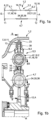
- the Figure 1a clarifies in a simplified schematic representation the basic structure and the basic principle of a device 1 designed according to the invention for damping vibrations, in particular in the form of a torsional vibration damper or torsional vibration damper.
- the device 1 according to the invention for damping vibrations is designed as a multi-stage series-parallel damper 2 .
- the device 1 for damping vibrations functionally comprises two damper stages 3, 4, each of which is formed by a damper arrangement—a first damper arrangement 5 and a second damper arrangement 7—and are connected in parallel. Connected in parallel means that both damper assemblies 5 and 7 are arranged in parallel in the power flow. The power flow takes place in parallel or via both damper assemblies 5 and 7.
- the first damper assembly 5 is designed according to the invention as a series damper, that is, it comprises at least two series-connected dampers 6.1 and 6.2. Connected in series means that the power transmission in the power flow takes place in series, in particular both dampers 6.1 and 6.2 in damper stage 3 are run through one after the other, with the direction being determined as a function of the direction in which the force is introduced. In figure 1 a, the power flow takes place, for example, via the damper 6.1 and 6.2.
- each of the damper stages 3 and 4 is effective in different operating ranges.
- the damper arrangement 7 of the second damper stage 4 is designed in such a way that it only becomes effective after a predefined twisting angle F, which is also referred to as the clearance angle.
- Both damper assemblies 5 and 7 are arranged in parallel and combined to form the two-stage series-parallel damper.
- Each of the individual damper assemblies 5 and 7 comprises rotating elements which are designed in one or more parts and, viewed in the direction of force flow, act as input parts and output parts, which are coupled to one another via means for torque transmission and/or means for damping coupling.
- the means for torque transmission and the means for damping coupling are preferably formed by the same structural units, preferably by spring units.
- the input and output parts of the individual damper assemblies 5, 7 and the individual dampers 6.1, 6.2 of the damper assembly 5 are each arranged coaxially with one another and can be rotated in relation to one another to a limited extent in the circumferential direction.
- the term input and output part refers to the power flow when arranged in a drive train from a driving to a driven component.
- the functions as an input and output part can be assigned to different components in different operating states, i.e. when used in vehicles in drive trains in traction mode, elements that can be coupled to a drive machine act as an input part, while the function is reversed in overrun mode by the element that functions as an output part in traction mode now functions as an input part.
- the device 1 comprises an input part E and an output part A viewed in the power flow.
- the input part E is formed by an element of the damper assembly 5 and the damper assembly 7 as a structural unit, or the input parts of the damper assemblies 5 and 7 are connected to one another in a torque-proof manner.
- the damper assembly 5 includes an input part 8 and an output part 10.
- the damper assembly 7 includes an input part 11 and an output part 12.
- the input parts 8 and 11 are preferably formed directly from the input part E and the output parts 10, 12 from the output part A.
- In the first Damper assembly 5 are two dampers connected in series, the damper 6.1 and the damper 6.2.
- the input 8 of the first damper arrangement which is non-rotatably connected to the input E of the overall unit or is preferably formed directly by this, is formed by the input part 13 of the first damper 6.1.
- the first damper 6.1 also includes an output part 14, which at the same time forms the input part 15 of the second damper 6.2 of the two series-connected dampers of the damper arrangement 5 or is connected to it in a rotationally fixed manner.
- the second damper 6.2 also includes an output part 16, which forms the output part 10 of the damper assembly 5 and which is connected to the output A in a torque-proof manner or forms it.
- the first damper 6.1 includes means 17 for torque transmission between the input part 13 and the output part 14 and means 18 for damping coupling.
- the second damper 6.2 includes means 20 for torque transmission and means 21 for damping coupling.
- the second damper arrangement 7 comprises at least one damper, in which the input part 11 and the output part 12 are coupled to one another via means 34 for torque transmission and means 35 for damping coupling.
- the power flow takes place between the input part E and the output part A of the device depending on the direction of rotation in the first damping arrangement 5 via the damper 6.1 and the damper 6.2 or vice versa and at the same time after reaching the predefined angle of rotation between the input part E and the output part A the damper arrangement 7.
- the second damper arrangement 7 does not become effective immediately when a twisting angle occurs between the input and output parts E, A, but only after a certain twisting angle has been reached between the input part E and the output part A. This angle is also known as a clearance angle designated. If this is reached, the second damper stage 4, which is formed by the second damper arrangement 7, is switched on.
- the figures 1b and 1c illustrate a device designed according to the invention for damping vibrations 1, in particular a multi-stage series-parallel damper arrangement 2 in two views.
- the Figure 1b clarified the device 1 for damping vibrations in axial section
- the Figure 1c shows a view B - B from the right.
- the arrangement of the flanges 23, 24 is shown in the neutral position, ie free of torque.
- the first damper stage 3 is arranged in the radial direction relative to the axis of rotation R of the device 1 on a larger diameter d 3 than the second further damper stage 4 on d 4 .
- the first damper arrangement 5 is thus arranged radially on the outside, while the second damper arrangement 7 is arranged within the extension of the inner diameter of the first damper arrangement 5 and thus at a smaller diameter d 4 .
- the input part E of the device 1 and thus the input parts 8, 10 of the damper assemblies 5, 7 are formed by two mutually spaced apart and coaxial driver disks 9.1 and 9.2, which are non-rotatably coupled to one another.
- the output part 10 is arranged between the driver disks 9.1 and 9.2 and is non-rotatably connected to the output part 12 of the damper arrangement 7 or preferably forms a structural unit in the form of one component and at the same time forms the output A with it.
- the first damper assembly 5 consists of the two dampers 6.1 and 6.2. The numbering of the input and output parts according to Figure 1a will be maintained.
- the input part 13 of the first damper 6.1 is formed by the driver disks 9.1 and 9.2. This also applies analogously to the input part 11 of the second damper arrangement 7, the input part 11 here also being formed by the driver disks 9.1 and 9.2 or with these elements coupled in a torque-proof manner.
- the first damper comprises means 17 for torque transmission between the input part 13 and the output part 14 and means 18 for damping coupling, with the means 17 and the means 18 being formed by a structural unit, in particular a spring unit 19, comprising at least one spring element in the form of a compression spring .
- the second damper 6.2 also includes means 20 for torque transmission and means 21 for damping coupling, these being formed by a further spring unit 22.
- the input part 13 is formed by the drive disks 9.1 and 9.2, the output part 14 by a so-called floating intermediate flange 23, which does not have its own bearing or non-rotatable connection to a connecting element.
- the intermediate flange 23 forms the input part 15 of the second damper 6.2.
- the output part 16 of the second damper 6.2 and thus the output part 10 or A of the device 1 is formed by a flange 24.
- the means 17 and 18 or the individual spring units 19 of the first damper 6.1 are supported in the driver disks 9.1 and 9.2, the flange 24 or the intermediate flange 23, while the spring units 22 of the second damper 6.2 are also supported on the driver disks 9.1, 9.2 or the Intermediate flange 23 and the flange 24 can support in the circumferential direction.
- the intermediate flange 23 is designed as a floating flange, i.e. it does not have its own bearing and is only held between the spring units 19, 22 by the spring units 19, 22 and the arrangement of the flange 24 or the side windows 9.1 and 9.2.
- the intermediate flange 23 is designed as an annular element, which has projections 25 on its inner circumference pointing in the direction of the axis of rotation R, which form stop surfaces 26 and 27 for the spring units 19 and 22 of the dampers 6.1 and 6.2, which are aligned in the circumferential direction and directed opposite to one another.
- the flange 24 here forms the output part 10, 12 of both the first and the second damper arrangement 5, 7 and thus also the output part A of the entire device 1 for damping vibrations. This is designed as a disc-shaped element.
- the intermediate flange 23 is an outer intermediate flange in the radial direction, which has the projections on its inner circumference 28, which are spaced apart uniformly in the circumferential direction.
- the flange 24, which forms the output part 10 or 12 of the damper assemblies 5, 7, is designed as a radially inner flange and points on its outer circumference 29 in the radial direction outwards, i.e.
- the flange 24 also includes recesses 33 on its diameter d 4 in the form of openings extending in the circumferential direction, which form support surfaces 37.1, 37.2 for the spring units 36 of the means 34 for torque transmission and 35 for damping coupling, respectively.
- the support surfaces 37.1, 37.2 are arranged opposite one another in the circumferential direction. However, these support surfaces 37.1, 37.2 only become effective after a certain angle of rotation F, which is between 3 and 50°, for example.
- the spring units 36 are supported on the side windows 9.1 and 9.2 and the flange 24.
- a torque is introduced into the damper assembly 5 via the driver disks 9.1 and 9.2, which are coupled to one another in a rotationally fixed manner, with Figure 1c depending on the direction of rotation, the spring units 19 or 22 are acted upon, which in turn act on the intermediate flange 23, in particular the projection 25 via the stop surfaces 26 or 27 and due to the resulting coupling, the torque is transmitted with simultaneous damping coupling via the intermediate flange 23 to the further spring unit, here for example the spring unit 22, and from this to the flange 24, which forms the output part A.
- the second damper stage 4 If there is a relative rotation between the driver disks 9.1, 9.2 and the flange 24 in the size of the clearance angle F, the second damper stage 4 also becomes effective. After this clearance angle F has been reached, the power is also transmitted via the second damper stage 4, also to the output 12 of the second damper stage 4, which acts as the output part A of the overall device.
- the individual spring units 19, 22, 36 are designed here, for example, in the form of so-called compression springs or as spiral springs. Other designs of elastic elements are also theoretically conceivable.
- the formation of the non-rotatable coupling between the driver disks 9.1 and 9.2 of the damper assembly 5 can take place in different ways.
- fastening elements 38 are provided, preferably in the form of rivets. These can be located radially outside the radial extent of the spring units 19, 22 of the damper stage 3, as in FIG Figure 1b shown. Furthermore, the arrangement can take place radially outside the outer diameter of the intermediate flange 23 .
- the non-rotatable coupling can simultaneously form a stop in the circumferential direction and thus limit the angle of rotation for the intermediate flange 23 or the flange 24 .
- the projections 30 on the outer circumference of the flange 24 also have stop surfaces 39.1, 39.2 which interact with stop surfaces 40.1, 40.2 which are correspondingly formed on the inner circumference 28 of the intermediate flange 23 and are aligned in the circumferential direction opposite to the stop surfaces 39.1, 39.2.
- stop surfaces 39.1, 39.2, 40.1, 40.2 are therefore arranged in such a way that they only form a twisting angle limit between intermediate flange 23 and flange 24 with a certain predefined spring deflection.
- the drive plates 9.1 and 9.2 act as the input part E and the flange 24 as the output part A. If the power flow is reversed, the flange 24 is assigned the function of the input part E while the Drive disks 9.1, 9.2 then act as output part A. If such a device in a drive train is coupled in both power flow directions with respect to the input and output parts to corresponding driving elements and elements to be driven, torque is always transmitted simultaneously with this device. If there is no coupling to one of the elements forming the input or output part E, A in a functional state, for example when overrun, the device 1 acts as an absorber, ie it compensates for vibrations but does not transmit any torque like an elastic coupling.
- the figure 1 illustrates a particularly compact device suitable for use in power transmission devices for vehicles, comprising a hydrodynamic component and a bridging device for the hydrodynamic component, which device is arranged in series with the hydrodynamic component and the bridging device.
- the figure 2 clarifies in a simplified schematic representation a side view of the side windows in the form of the driver disks 9.1 and 9.2 of the device 1 according to FIG figure 1 .
- a disk-shaped configuration in the form of an annular disk with openings 41 formed in the circumferential direction for receiving the spring units 19 and 22 of the dampers 6.1 and 6.2 and supports in the circumferential and radial directions can also be seen here.
- the driver disks have openings 42 for the second damper arrangement 7 which are arranged on a smaller diameter and accommodate the spring unit 36 .
- the embodiment according to the invention figure 1 and 2 is characterized by a high degree of concentration of functions, a high degree of compactness and at the same time a small number of components. It is also possible with this embodiment to design a torsional vibration damper with the lowest possible spring rate, which has the largest possible torsion angle with low friction. This is also realized in that the series damper arrangement is preferably arranged on the larger diameter.
- the figure 3 illustrates the damper characteristic for the entire damper unit using a torsion angle/torque diagram ⁇ /M. From this it can be seen that in a first twisting angle range, which is characterized by a small twisting angle and low moments, it runs flatter and when the second damper stage 4 is switched on, the characteristic curve rises.
- the first area is labeled I and the second area is labeled II.
Landscapes
- Engineering & Computer Science (AREA)
- General Engineering & Computer Science (AREA)
- Mechanical Engineering (AREA)
- Physics & Mathematics (AREA)
- Acoustics & Sound (AREA)
- Aviation & Aerospace Engineering (AREA)
- Mechanical Operated Clutches (AREA)
- Buildings Adapted To Withstand Abnormal External Influences (AREA)
Description
- Die Erfindung betrifft eine Kraftübertragungseinrichtung umfassend eine Vorrichtung zur Dämpfung von Schwingungen, insbesondere einen mehrstufigen Drehschwingungsdämpfer, umfassend zumindest zwei parallel geschaltete, koaxial angeordnete Dämpferanordnungen, eine erste Dämpferanordnung und eine zweite Dämpferanordnung.
- Vorrichtungen zur Dämpfung von Schwingungen, insbesondere in Form von mehrstufigen Drehschwingungsdämpfern beziehungsweise Torsionsschwingungsdämpfern, sind in einer Vielzahl von Ausführungen aus dem Stand der Technik vorbekannt. Diese fungieren bei Anordnung in einem Antriebsstrang in Kraftflussrichtung betrachtet zwischen einem Antrieb und einem Abtrieb und Kopplung mit den diese bildenden Anschlusselementen als elastische Kupplung. Diese überträgt Drehmoment und kompensiert gleichzeitig Schwingungen bei Leistungsübertragung. Denkbar ist auch eine Ausführung als Tilger. In diesem Fall erfolgt über die Vorrichtung zwischen den benachbarten Anschlusselementen keine Drehmomentübertragung, sondern es werden über die einzelnen Komponenten lediglich Drehmomentstöße abgebaut. Derartige Vorrichtungen zur Dämpfung von Schwingungen basieren je nach Dämpfungsart auf unterschiedlichen Funktionsprinzipien. Bekannt sind neben rein mechanischen Dämpferlösungen auch hydraulische oder kombiniert mechanisch- hydraulische Dämpferlösungen. Mechanische Dämpfer umfassen einen ein- oder mehrteiligen, je nach Kraftflussrichtung als Eingangsteil oder Ausgangsteil der Vorrichtung zur Dämpfung von Schwingungen fungierenden Drehteil, insbesondere einen Primärteil und einen Sekundärteil, die koaxial zueinander angeordnet sind und in Umfangsrichtung relativ zueinander begrenzt verdrehbar sind. Die Kopplung zwischen dem Eingangsteil und dem Ausgangsteil erfolgt über Mittel zur Drehmomentübertragung und Mittel zur Dämpfung von Schwingungen, die in der Regel von Federeinheiten, umfassend zumindest ein Federelement in Form einer Druckfeder gebildet werden. Über die Größe des Verdrehwinkels zwischen Eingangsteil und Ausgangsteil und die Federkraft können die Schwingungen kompensiert und abgebaut werden.
- Aus der Druckschrift
DE 30 47 039 A1 ist eine Ausführung einer zweistufigen Vorrichtung zur Dämpfung von Schwingungen zur Übertragung von Drehmoment zwischen einem Antrieb und einem Abtrieb vorbekannt, welche zwei in Reihe geschaltete Dämpferanordnungen umfasst. Um eine größere Relativbewegung zwischen den treibenden und getriebenen Elementen der Vorrichtung zur Dämpfung von Schwingungen zu ermöglichen, wurde die Vorrichtung zweistufig ausgeführt. Diese weist dabei zwei konzentrische Kreise von Dämpfungsfedern auf, die in einem Gehäuse angeordnet sind und von Antriebszungen angetrieben werden, die an einem Antriebselement montiert sind, beispielsweise einer Kolbenplatte für eine Sperrkupplung. Schwimmende Elemente separieren dabei die Federn in den inneren und äußeren Federkreisen in zwei oder mehreren Federgruppen. Dabei arbeiten die zwei oder mehreren Federgruppen in jedem Kreis parallel zueinander, während die Federn in jeder einzelnen Gruppe in Reihe wirken. Im Kraftfluss erfolgt damit die Leistungsübertragung in Reihe. Der innen liegende Dämpfer ist frei von einem Verdrehspiel, das heißt ist immer wirksam. - Aus der Druckschrift
US 2004/0216979 A1 ist eine Ausführung einer Vorrichtung zur Dämpfung von Schwingungen, umfassend zumindest zwei Dämpferanordnungen, vorbekannt, die parallel geschaltet sind, wobei beide Dämpferanordnungen immer wirksam sind. Die Dämpferanordnung für die kleineren Verdrehwinkel ist hier auf einem radial inneren Durchmesser angeordnet, während das größere Verdrehspiel über die zweite Dämpferanordnung auf einem radial äußeren Durchmesser realisiert wird. Die radial innere Dämpferanordnung ist als Reihendämpfer ausgeführt, umfassend über einen Flansch separierte und hintereinander geschaltete Federelemente. - Aus der Druckschrift
US 2004/0185940 ist eine als Reihen-Parallel-Dämpfer ausgeführte Vorrichtung zur Dämpfung von Schwingungen vorbekannt, umfassend ein erstes Drehelement und ein zweites Drehelement, die relativ zueinander begrenzt in Umfangsrichtung verdrehbar sind. Ferner umfasst die Vorrichtung ein Paar von ersten, in einer Drehrichtung ausgerichteten und in Reihe geschalteten elastischen Elementen, die über einen schwimmenden Zwischenflansch gekoppelt sind, und ein weiteres zweites elastisches Element, das parallel zu den ersten elastischen Elementen geschaltet ist, wobei das zweite elastische Element derart ausgelegt ist, in der Drehrichtung zusammengedrückt zu werden, nachdem das Paar von ersten elastischen Elementen aufgrund einer relativen Drehung des ersten Drehelementes und des zweiten Drehelementes auf einen ersten Winkel zusammengedrückt wurde. Dem zweiten elastischen Element ist dazu ein Freiwinkel zugeordnet, der im schwimmenden Flansch integriert ist. Die Anordnung von ersten und zweiten elastischen Elementen erfolgt zur Verringerung des radialen Bauraumes auf einem Durchmesser oder in radialer Richtung hinsichtlich der sich durch die Erstreckung der Federelemente theoretisch ergebenden ringförmigen Bereiche einander überlappend. Die Kopplung zwischen den ersten elastischen Elementen erfolgt über einen schwimmenden Flansch. - Eine weitere Ausführung einer Reihen-Parallel-Dämpfervorrichtung ist aus der Druckschrift
US 3,138 011 vorbekannt. Der dort beschriebene Dämpfer weist einen Abtriebsflansch auf, der einstückig ausgeführt ist, jedoch in seiner Herstellung und Ausgestaltung sehr aufwendig ist. - Weiterhin zeigt die
US 2007/0051577 A1 eine Dämpferanordnung zum Dämpfen des von einer Turbine eines Drehmomentenwandlers an ein Getriebe abgegebenen Drehmoments. Hierbei wird vorgeschlagen, zwischen einer Deckplatte und einem Abtriebsflansch einen ersten (einzelnen) Dämpfer in Reihe zu einer Parallelschaltung aus zwei Dämpfern anzuordnen. DieJP-A-10047453 - Allen vorgenannten Ausführungen gemeinsam ist die Erzielung einer Federkennlinie im Hinblick auf ein gewünschtes Verhalten in einem bestimmten Betriebsbereich.
- Der Erfindung liegt daher die Aufgabe zugrunde, eine Kraftübertragungseinrichtung umfassend eine Vorrichtung zur Dämpfung von Schwingungen mit niedriger Federrate bei geringen Drehmomenten zu schaffen, wobei die Vorrichtung zur Dämpfung von Schwingungen durch eine relativ flache Kennliniencharakteristik charakterisiert ist. Dieser auf die Übertragung eines Teiles des theoretisch maximal möglichen Momentes auslegbare Kennfeldbereich soll dabei durch einen möglichst großen Verdrehwinkelbereich zwischen den als Ein- und Ausgangsteil fungierenden Drehelementen beschreibbar sein. Die erfindungsgemäße Lösung soll sich dabei durch einen geringen konstruktiven und fertigungstechnischen Aufwand auszeichnen und ferner zur Integration in Kraftübertragungsvorrichtungen für den Einsatz in Antriebssträngen geeignet sein, wobei die Vorrichtung zur Dämpfung von Schwingungen möglichst in radialer und axialer Richtung klein bauen soll.
- Die erfindungsgemäße Lösung ist durch die Merkmale des Anspruches 1 charakterisiert. Vorteilhafte Ausgestaltungen sind in den Unteransprüchen beschrieben.
- Eine Vorrichtung zur Dämpfung von Schwingungen, insbesondere ein mehrstufiger Reihen-Parallel-Drehschwingungsdämpfer, umfasst zumindest zwei parallel geschaltete und koaxial angeordnete und mindestens einen Eingangs- und einen Ausgangsteil aufweisende Dämpferanordnungen, eine erste Dämpferanordnung und eine zweite Verdrehspiel aufweisende Dämpferanordnung, wobei eine der Dämpferanordnungen als Reihendämpfer, umfassend zwei zumindest in Reihe geschaltete und über einen Zwischenflansch gekoppelte einzelne Dämpfer, ausgebildet ist. Die Anordnung der ersten Dämpferanordnung erfolgt erfindungsgemäß auf einem Durchmesser in radialer Richtung, der größer ist als der Durchmesser der Anordnung der zweiten Dämpferanordnung. Ausgangsteil der ersten Dämpferanordnung und Ausgangsteil der zweiten Dämpferanordnung bilden eine bauliche Einheit.
- Die erfindungsgemäße Lösung ermöglicht es zum einen, eine sehr kompakte kombinierte Dämpfungsanordung zu schaffen, bei welcher der Schwingungsdämpfer durch eine möglichst niedrige Federrate in einem möglichst großen Verdrehwinkelbereich mit niedriger Reibung charakterisiert ist. Die Herstellung ist aufgrund der Funktionskonzentration in einzelnen Bauteilen relativ einfach und mit geringen Kosten verbunden.
- Die zweite Dämpferanordnung ist dabei möglichst in geringem Abstand zur Rotationsachse angeordnet. Beide Dämpferanordnungen sind koaxial zueinander angeordnet und können in axialer Richtung mit Versatz oder aber vorzugsweise in einer Ebene angeordnet werden. Im letztgenannten Fall baut die Dämpferanordnung in Form des mehrstufigen Dämpfers, bei welchem die Dämpferkennlinie aufgrund der separaten Ausgestaltung der einzelnen Dämpferanordnung variabel eingestellt werden kann, in axialer Richtung und auch radialer Richtung relativ klein.
- Aufgrund der Anordnung der ersten Dämpferanordnung in radialer Richtung außen können über diese große Verdrehwinkel realisiert werden, wobei die erste Dämpferanordnung in diesem Verdrehwinkelbereich wirksam ist und somit eine Dämpfung auch bei höheren Momenten realisiert werden kann. In einer besonders vorteilhaften Ausführung umfasst die erste Dämpferanordnung zumindest zwei in Reihe geschaltete Dämpfer, einen ersten und einen zweiten Dämpfer, wobei jeweils das Ausgangsteil eines Dämpfers den Eingangsteil des anderen Dämpfers bildet oder aber drehfest mit diesem gekoppelt ist. Gemäß einer besonders vorteilhaften Ausführung wird dabei der Reihendämpfer auf einem gemeinsamen Durchmesser realisiert, das heißt, die zwei einzelnen Dämpfer sind auf einem gemeinsamen Durchmesser angeordnet und frei von Versatz in radialer Richtung. In diesem Fall können die radialen Abmessungen für den Gesamtdämpfer gering gehalten werden.
- Jeder der einzelnen Dämpfer einer Reihendämpferanordnung weist dazu vorzugsweise identisch dimensionierte Mittel zur Drehmomentübertragung und/oder Mittel zur Dämpfungskopplung auf. Dadurch ist es möglich, bei entsprechender Integration im Gesamtsystem hier auch eine Verdrehwinkelrichtungsunabhängigkeit zu realisieren und in jedem Fall das Drehmoment über den Ausgang der ersten Dämpferanordnung in Kombination mit dem über die zweite Dämpferanordnung geleiteten Moment zu einem anzutreibenden Element in einem Antriebsstrang zu leiten.
- Gemäß einer weiteren Ausführung ist es auch denkbar, die einzelnen Dämpfer der ersten Dämpferanordnung auf unterschiedlichen Durchmessern anzuordnen. In diesem Fall können theoretisch auch die Übertragungselemente unterschiedlich ausgelegt werden.
- Die einzelnen Dämpfer der als Reihendämpfer ausgeführten ersten Dämpferanordnung sind über einen Zwischenflansch, der je nach Anbindung als Mitnehmerscheibe oder als schwimmender Flansch ausgeführt sein kann, miteinander gekoppelt. Dieser ist dazu als ringförmiges Element mit in radialer Richtung am Innenumfang in Richtung zur Rotationsachse weisenden und in Umfangsrichtung ausgerichtete Anschlagflächen für die Mittel zur Drehmomentübertragung und Dämpfungskopplung bildenden Vorsprüngen ausgeführt.
- Ein weiterer radial innerhalb der Erstreckung des Zwischenflansches liegender Flansch, der als ringförmiges Element mit am Außenumfang in radialer Richtung ausgerichteten Vorsprüngen ausgeführt. Dieses fungiert je nach Anbindung als Ein- oder Ausgangsteil für die zweite Dämpferanordnung.
- Das Verdrehspiel der zweiten Dämpferanordnung ist durch einen vordefinierten, einen Freiwinkel beschreibenden Verdrehwinkel zwischen Eingangsteil und Ausgangsteil der zweiten Dämpferanordnung charakterisiert, in welchem die zweite Dämpferanordnung nicht wirksam ist. Der Verdrehwinkel ist im Ausgangsteil integriert.
- Jede der einzelnen Dämpferanordnungen umfasst in Kraftflussrichtung betrachtet einen als Eingangsteil fungierenden Primärteil und einen als Ausgangsteil fungierenden Sekundärteil. Die Funktion ist je nach Kraftflussrichtung und Änderung dieser austauschbar, das heißt wechselt. Dabei können die Eingangs- und Ausgangsteile einteilig oder mehrteilig ausgebildet werden. Vorzugsweise werden jeweils einteilige Ausführungen in Scheibenform gewählt. Diese sind über die Mittel zur Drehmomentübertragung und Mittel zur Dämpfungskopplung miteinander gekoppelt. Die Mittel zur Drehmomentübertragung und zur Dämpfungskopplung werden von elastischen Elementen, insbesondere Federeinheiten, gebildet. Dabei sind die einzelnen Federeinheiten als Einzelfeder ausgeführt oder aber können auch als hintereinander geschaltete Federeinheiten vorliegen. Die einzelne Dämpferanordnung fungiert dabei jeweils als elastische Kupplung, die Drehmoment überträgt und gleichzeitig Schwingungen kompensiert. Die erste Dämpferanordnung umfasst zumindest sowohl einen Eingangsteil als auch einen Ausgangsteil. Das gleiche gilt für die zweite Dämpferanordnung, wobei jedoch der Eingangsteil der ersten und der zweiten Dämpferanordnung miteinander gekoppelt beziehungsweise parallel geschaltet sind, so dass hier eine Momentenaufteilung über die beiden Dämpferanordnungen erfolgen kann.
- Zur Realisierung der Parallelschaltung bilden Eingangs- und Ausgangsteile der einzelnen Dämpferanordnungen eine bauliche Einheit, d.h. können beispielsweise miteinander drehfest gekoppelt sein. In diesem Fall sind die einzelnen Eingangs- und Ausgangsteile als separate Elemente ausgeführt, die funktional lediglich über die Verbindung miteinander gekoppelt sind. Gemäß einer besonders vorteilhaften Ausführung wird jedoch eine integrale Bauweise angestrebt, das heißt, Eingangsteil und Ausgangsteil der ersten und zweiten Dämpferanordnung sind jeweils einteilig ausgeführt, das heißt, die den Eingangsteil beziehungsweise Ausgangsteil bildenden Elemente der ersten Dämpferanordnung sind gleichzeitig als Eingangsteil beziehungsweise Ausgangsteil der zweiten Dämpferanordnung ausgeführt.
- Die Vorrichtung ist als mechanischer Reibdämpfer ausgeführt. Diese umfasst im einfachsten Fall zumindest zwei in axialer Richtung angeordnete und drehfest miteinander gekoppelte Seitenscheiben, die als Mitnehmerscheiben oder als Ausgangsteil fungieren können. Die Seitenscheiben umfassen dabei in Umfangsrichtung ausgebildete Öffnungen zur Aufnahme und Ausbildung von einander entgegengesetzt ausgebildeten Anschlagflächen für die Federelemente der einzelnen Dämpferanordnungen und der Dämpfer der ersten Dämpferanordnung. Dabei sind die Anschlagflächen in Umfangsrichtung bildenden Ausnehmungen beziehungsweise Durchgangsöffnungen derart zueinander angeordnet, dass für die zweite Dämpferanordnung ein Freiwinkel, das heißt ein Verdrehbereich zwischen Eingangs- und Ausgangsteil realisierbar ist, der keinerlei Wirkung im Hinblick auf die zweite Dämpfervorrichtung zeigt, das heißt, die zweite Dämpfervorrichtung erst dann wirksam wird, wenn ein bestimmter vordefinierter Verdrehwinkel zwischen Eingangsteil und Ausgangsteil erzielt wird.
- In Analogie gilt diese Aussage auch für den zwischen den beiden Seitenscheiben angeordneten Flansch, insbesondere das scheibenförmige Element in Form des Flansches, der gleichzeitig den Ausgangsteil der ersten und der zweiten Dämpferanordnung bildet.
- Je nach Zuordnung und Kopplung beziehungsweise Anbindung in einer Kraftübertragungseinheit können die unterschiedlichen Elemente jeweils als Eingangsteil fungieren. Dies hängt davon ab, welche der Elemente mit der Antriebsanordnung gekoppelt werden und welche mit der Abtriebsseite in Kraftflussrichtung betrachtet. Gemäß einer ersten Ausführung kann der Antrieb über Seitenscheiben realisiert werden. In diesem Fall sind diese drehfest mit einem antreibenden Element, beispielsweise in einer Kraftübertragungsvorrichtung einer Überbrückungskupplung oder einer Antriebsmaschine wenigstens mittelbar gekoppelt. Die Leistungsübertragung erfolgt dann in der ersten Dämpferanordnung auf den Zwischenflansch und von diesem auf den Flansch, welcher das Ausgangsteil der Vorrichtung sowie den Ausgangsteil der zweiten Dämpferanordnung bildet.
- Gemäß einer weiteren zweiten Ausführung ist es auch denkbar, die Leistung über den Flansch einzuleiten. In diesem Fall erfolgt die Leistungsübertragung auf die Seitenscheiben der ersten und zweiten Dämpferanordnung, die als Ausgangsteil fungieren.
- Die erfindungsgemäße Lösung ist nicht auf die beschriebenen Ausführungen beschränkt. Konstruktive Details liegen im Ermessen des zuständigen Fachmannes.
- Die erfindungsgemäße Lösung ist nachfolgend anhand von Figuren erläutert. Darin ist im Einzelnen Folgendes dargestellt:
- Figur 1a
- verdeutlicht in schematisiert vereinfachter Darstellung den Grundaufbau und das Grundprinzip einer erfindungsgemäßen Vorrichtung zur Dämpfung von Schwingungen in Form eines Reihen-Parallel-Dämpfers;
- Figuren 1b und 1c
- verdeutlichen in schematisiert vereinfachter Darstellung anhand zweier Ansichten, insbesondere eines Axialschnittes und einer Ansicht B-B gemäß
Figur 1b eine erfindungsgemäße Vorrichtung zur Dämpfung von Schwingungen in Form eines zweistufigen Reihen-Parallel-Dämpfers; - Figur 2
- verdeutlicht in einer Seitenansicht die Ausführung der Seitenscheiben der Dämpferanordnung;
- Figur 3
- verdeutlicht anhand eines Diagramms die Kennlinie einer erfindungsgemäß ausgeführten mehrstufigen Vorrichtung zur Dämpfung von Schwingungen.
- Die
Figur 1a verdeutlicht in schematisiert vereinfachter Darstellung den Grundaufbau und das Grundprinzip einer erfindungsgemäß ausgeführten Vorrichtung 1 zur Dämpfung von Schwingungen, insbesondere in Form eines Drehschwingungsdämpfers beziehungsweise Torsionsschwingungsdämpfers. Die erfindungsgemäße Vorrichtung 1 zur Dämpfung von Schwingungen ist als mehrstufiger Reihen-Parallel-Dämpfer 2 ausgeführt. Die Vorrichtung 1 zur Dämpfung von Schwingungen umfasst funktional zwei Dämpferstufen 3,4, die jeweils von einer Dämpferanordnung - einer ersten Dämpferanordnung 5 und einer zweiten Dämpferanordnung 7 - gebildet werden und parallel geschaltet sind. Parallel geschaltet bedeutet dabei, dass beide Dämpferanordnungen 5 und 7 im Kraftfluss parallel angeordnet sind. Der Kraftfluss erfolgt parallel beziehungsweise über beide Dämpferanordnungen 5 und 7. Die erste Dämpferanordnung 5 ist dabei erfindungsgemäß als Reihendämpfer ausgeführt, das heißt, umfasst zumindest zwei in Reihe geschaltete Dämpfer 6.1 und 6.2. In Reihe geschaltet bedeutet dabei, dass die Leistungsübertragung im Kraftfluss in Reihe erfolgt, insbesondere beide Dämpfer 6.1 und 6.2 in der Dämpferstufe 3 nacheinander durchlaufen werden, wobei die Richtung in Abhängigkeit von der Krafteinleitungsrichtung bestimmt wird. InFigur 1 a erfolgt der Kraftfluss beispielhaft über den Dämpfer 6.1 und 6.2. - Jede der Dämpferstufen 3 und 4 ist dabei in unterschiedlichen Betriebsbereichen wirksam. Insbesondere ist die Dämpferanordnung 7 der zweiten Dämpferstufe 4 derart ausgeführt, dass diese erst nach einem vordefinierten Verdrehwinkel F, welcher auch als Freiwinkel bezeichnet wird, wirksam wird. Beide Dämpferanordnungen 5 und 7 sind parallel angeordnet und zu dem zweistufigen Reihen-Parallel-Dämpfer zusammengefasst. Jede der einzelnen Dämpferanordnungen 5 und 7 umfasst ein- oder mehrteilig ausgeführte und in Kraftflussrichtung betrachtet als Eingangsteile und Ausgangsteile fungierende Drehelemente, die über Mittel zur Drehmomentübertragung und/oder Mittel zur Dämpfungskopplung miteinander gekoppelt sind. Vorzugsweise werden beim Einsatz mechanischer Dämpfungskonzepte die Mittel zur Drehmomentübertragung und die Mittel zur Dämpfungskopplung von den gleichen Baueinheiten gebildet, vorzugsweise von Federeinheiten. Dabei sind die Eingangs- und Ausgangsteile der einzelnen Dämpferanordnungen 5, 7 und der einzelnen Dämpfer 6.1, 6.2 der Dämpferanordnung 5 jeweils koaxial zueinander angeordnet und in Umfangsrichtung begrenzt gegeneinander verdrehbar. Der Begriff Ein- und Ausgangsteil bezieht sich dabei in Kraftflussrichtung betrachtet auf den Kraftfluss bei Anordnung in einem Antriebsstrang von einem treibenden zu einem getriebenen Bauteil. Die Funktionen als Ein- und Ausgangsteil können dabei unterschiedlichen Bauteilen in unterschiedlichen Betriebszuständen zugeordnet sein, das heißt beim Einsatz in Fahrzeugen in Antriebssträngen im Traktionsbetrieb fungieren Elemente, die mit einer Antriebsmaschine koppelbar sind, als Eingangsteil, während im Schubbetrieb eine Umkehr der Funktion erfolgt, indem das im Traktionsbetrieb als Ausgangsteil fungierende Element nunmehr als Eingangsteil fungiert.
- Die Vorrichtung 1 umfasst im Kraftfluss betrachtet einen Eingangsteil E und einen Ausgangsteil A. Der Eingangsteil E wird dabei von einem Element der Dämpferanordnung 5 und der Dämpferanordnung 7 als bauliche Einheit gebildet oder aber die Eingangsteile der Dämpferanordnungen 5 und 7 sind drehfest miteinander verbunden. Die Dämpferanordnung 5 umfasst einen Eingangsteil 8 und einen Ausgangsteil 10. Die Dämpferanordnung 7 umfasst einen Eingangsteil 11 und ein Ausgangsteil 12. Dabei werden die Eingangsteile 8 und 11 vorzugsweise direkt vom Eingangsteil E gebildet und die Ausgangsteile 10, 12 vom Ausgangsteil A. In der ersten Dämpferanordnung 5 sind zwei Dämpfer in Reihe geschaltet, der Dämpfer 6.1 und der Dämpfer 6.2. Dabei wird der Eingang 8 der ersten Dämpferanordnung, der drehfest mit dem Eingang E der Gesamteinheit verbunden ist oder vorzugsweise von diesem direkt gebildet wird, vom Eingangsteil 13 des ersten Dämpfers 6.1 gebildet. Der erste Dämpfer 6.1 umfasst ferner einen Ausgangsteil 14, der gleichzeitig den Eingangsteil 15 des zweiten Dämpfers 6.2 der beiden in Reihe geschalteten Dämpfer der Dämpferanordnung 5 bildet oder mit diesem drehfest verbunden ist. Der zweite Dämpfer 6.2 umfasst ferner einen Ausgangsteil 16, der den Ausgangsteil 10 der Dämpferanordnung 5 bildet und der mit dem Ausgang A drehfest verbunden ist oder diesen bildet. Der erste Dämpfer 6.1 umfasst Mittel 17 zur Drehmomentübertragung zwischen dem Eingangsteil 13 und dem Ausgangsteil 14 und Mittel 18 zur Dämpfungskopplung. In Analogie umfasst der zweite Dämpfer 6.2 Mittel 20 zur Drehmomentübertragung und Mittel 21 zur Dämpfungskopplung. Die zweite Dämpferanordnung 7 umfasst zumindest einen Dämpfer, bei welchem der Eingangsteil 11 und der Ausgangsteil 12 über Mittel 34 zur Drehmomentübertragung und Mittel 35 zur Dämpfungskopplung miteinander gekoppelt sind. Der Kraftfluss erfolgt zwischen dem Eingangsteil E und dem Ausgangsteil A der Vorrichtung je nach Drehrichtung in der ersten Dämpfungsanordnung 5 über den Dämpfer 6.1 und den Dämpfer 6.2 beziehungsweise umgekehrt und gleichzeitig nach Erreichen des vordefinierten Verdrehwinkels zwischen Eingangsteil E und Ausgangsteil A die Dämpferanordnung 7.
- In der
Figur 1a im Grundprinzip nicht dargestellt ist, dass die zweite Dämpferanordnung 7 nicht sofort bei Auftreten eines Verdrehwinkels zwischen Ein- und Ausgangsteil E, A wirksam wird, sondern erst nach Erreichen eines bestimmten Verdrehwinkels zwischen dem Eingangsteil E und dem Ausgangsteil A. Dieser Winkel wird auch als Freiwinkel bezeichnet. Wird dieser erreicht, wird die zweite Dämpferstufe 4, welche von der zweiten Dämpferanordnung 7 gebildet wird, zugeschaltet. - Die
Figuren 1b und1c verdeutlichen eine erfindungsgemäß ausgeführte Vorrichtung zur Dämpfung von Schwingungen 1, insbesondere eine mehrstufige Reihen-Parallel-Dämpferanordnung 2 in zwei Ansichten. DieFigur 1b verdeutlicht die Vorrichtung 1 zur Dämpfung von Schwingungen im Axialschnitt, dieFigur 1c zeigt eine Ansicht B - B von rechts. In dieser Ansicht ist insbesondere die Anordnung der Flansche 23, 24 in der Neutralstellung, d.h. frei von Drehmoment dargestellt. - Die Anordnung der ersten Dämpferstufe 3 erfolgt in radialer Richtung bezogen auf die Rotationsachse R der Vorrichtung 1 auf einem größeren Durchmesser d3 als die zweite weitere Dämpferstufe 4 auf d4. Damit erfolgt die Anordnung der ersten Dämpferanordnung 5 radial außen, während die Anordnung der zweiten Dämpferanordnung 7 innerhalb der Erstreckung des Innendurchmessers der ersten Dämpferanordnung 5 und damit auf einem kleineren Durchmesser d4 erfolgt. Der Eingangsteil E der Vorrichtung 1 und damit die Eingangsteile 8, 10 der Dämpferanordnungen 5, 7 werden von zwei nebeneinander beabstandet angeordneten und koaxial zueinander ausgebildeten Mitnehmerscheiben 9.1 und 9.2 gebildet, die drehfest miteinander gekoppelt sind. Zwischen den Mitnehmerscheiben 9.1 und 9.2 ist der Ausgangsteil 10 angeordnet, der drehfest mit dem Ausgangsteil 12 der Dämpferanordnung 7 verbunden ist oder aber mit diesem vorzugsweise eine bauliche Einheit in Form eines Bauteils und gleichzeitig den Ausgang A bildet. Die erste Dämpferanordnung 5 besteht aus den zwei Dämpfern 6.1 und 6.2. Die Nummerierung der Ein- und Ausgangsteile gemäß
Figur 1a wird beibehalten. Der Eingangsteil 13 des ersten Dämpfers 6.1 wird dabei von den Mitnehmerscheiben 9.1 und 9.2 gebildet. Dies gilt in Analogie auch für den Eingangsteil 11 der zweiten Dämpferanordnung 7, wobei der Eingangsteil 11 hier ebenfalls von den Mitnehmerscheiben 9.1 und 9.2 gebildet wird oder aber mit diesen drehfest gekoppelten Elementen. Der erste Dämpfer umfasst Mittel 17 zur Drehmomentübertragung zwischen dem Eingangsteil 13 und dem Ausgangsteil 14 und Mittel 18 zur Dämpfungskopplung, wobei hier die Mittel 17 und die Mittel 18 von einer Baueinheit, insbesondere einer Federeinheit 19, umfassend zumindest ein Federelement in Form einer Druckfeder gebildet werden. In Analogie umfasst auch der zweite Dämpfer 6.2 Mittel 20 zur Drehmomentübertragung und Mittel 21 zur Dämpfungskopplung, wobei diese von einer weiteren Federeinheit 22 gebildet werden. Der Eingangsteil 13 wird, wie bereits ausgeführt, von den Mitnehmerscheiben 9.1 und 9.2 gebildet, der Ausgangsteil 14 von einem so genannten schwimmenden Zwischenflansch 23, der frei von einer eigenen Lagerung oder drehfesten Anbindung an ein Anschlusselement ist. Der Zwischenflansch 23 bildet den Eingangsteil 15 des zweiten Dämpfers 6.2. Der Ausgangsteil 16 des zweiten Dämpfers 6.2 und damit der Ausgangsteil 10 beziehungsweise A der Vorrichtung 1 wird von einem Flansch 24 gebildet. Die Mittel 17 und 18 beziehungsweise die einzelnen Federeinheiten 19 des ersten Dämpfers 6.1 stützen sich in den Mitnehmerscheiben 9.1 und 9.2, dem Flansch 24 oder dem Zwischenflansch 23 ab, während die Federeinheiten 22 des zweiten Dämpfers 6.2 sich ebenfalls an den Mitnehmerscheiben 9.1, 9.2 oder dem Zwischenflansch 23 und dem Flansch 24 in Umfangsrichtung abstützen können. - Der Zwischenflansch 23 ist in dieser Ausführung als schwimmender Flansch ausgebildet, das heißt, dieser besitzt keine eigene Lagerung und wird lediglich durch die Federeinheiten 19, 22 und die Anordnung des Flansches 24 beziehungsweise der Seitenscheiben 9.1 und 9.2 zwischen den Federeinheiten 19, 22 gehalten. Der Zwischenflansch 23 ist als ringförmiges Element ausgeführt, welches an seinem Innenumfang in Richtung zur Rotationsachse R weisende Vorsprünge 25 aufweist, die in Umfangsrichtung ausgerichtete und einander entgegengesetzt gerichtet Anschlagflächen 26 und 27 für die Federeinheiten 19 beziehungsweise 22 der Dämpfer 6.1 und 6.2 bilden.
- Der Flansch 24 bildet hier den Ausgangsteil 10, 12 sowohl der ersten als auch der zweiten Dämpferanordnung 5, 7 und damit auch den Ausgangsteil A der gesamten Vorrichtung 1 zur Dämpfung von Schwingungen. Dieser ist dazu als scheibenförmiges Element ausgebildet.
- In der in der
Figur 1c dargestellten Ausführung handelt es sich beim Zwischenflansch 23 um einen in radialer Richtung äußeren Zwischenflansch, welcher an seinem Innenumfang 28 die Vorsprünge aufweist, die zueinander gleichmäßig beabstandet in Umfangsrichtung ausgeführt sind. Der Flansch 24, welcher den Ausgangsteil 10 beziehungsweise 12 der Dämpferanordnungen 5, 7 bildet, ist als radial innerer Flansch ausgeführt und weist an seinem Außenumfang 29 in radialer Richtung nach außen, das heißt sich von der Rotationsachse R weg erstreckende und in Umfangsrichtung im gleichmäßigen Abstand zueinander angeordnete Vorsprünge 30 auf, wobei zwei einander benachbarte Vorsprünge 30 sich in Umfangsrichtung erstreckende randoffene Aussparungen beschreiben, in welchen die beiden Federeinheiten 19 und 22 der einzelnen Dämpfer 6.1 und 6.2 angeordnet werden und sich an den einander gegenüberliegenden Seitenflächen 31 und 32 einer derartigen Aussparung am Flansch 24 abstützen. Der Flansch 24 beinhaltet auf seinem Durchmesser d4 ferner Ausnehmungen 33 in Form von sich in Umfangsrichtung erstreckenden Öffnungen, welche Abstützflächen 37.1, 37.2 für die Federeinheiten 36 der Mittel 34 zur Drehmomentübertragung beziehungsweise 35 zur Dämpfungskopplung bilden. Die Abstützflächen 37.1, 37.2 sind in Umfangsrichtung einander gegenüberliegend angeordnet. Diese Abstützflächen 37.1, 37.2 werden jedoch erst nach einem bestimmten Verdrehwinkel F, welcher beispielsweise zwischen 3 bis 50° beträgt, wirksam. Die Federeinheiten 36 stützen sich an den Seitenscheiben 9.1 und 9.2 und dem Flansch 24 ab. - Bei dieser Ausführung wird in Kraftflussrichtung beim Einsatz in Antriebssträngen und Fahrzeugen im normalen Traktionsbetrieb von der Antriebsmaschine zu einer nachgeordneten Leistungsübertragungseinheit betrachtet über die Mitnehmerscheiben 9.1 und 9.2, welche drehfest miteinander gekoppelt sind, ein Moment in die Dämpferanordnung 5 eingeleitet, wobei gemäß
Figur 1c je nach Drehrichtung die Federeinheiten 19 oder 22 beaufschlagt werden, die wiederum auf den Zwischenflansch 23, insbesondere den Vorsprung 25 über die Anschlagflächen 26 beziehungsweise 27 wirken und aufgrund der dadurch bedingten Kopplung die Drehmomentübertragung bei gleichzeitiger Dämpfungskopplung über den Zwischenflansch 23 auf die weitere Federeinheit, hier beispielsweise die Federeinheit 22, und von dieser auf den Flansch 24, der den Ausgangsteil A bildet, bewirken. Erfolgt eine Relativverdrehung zwischen den Mitnehmerscheiben 9.1, 9.2 und dem Flansch 24 in Größe des Freiwinkels F, wird auch die zweite Dämpferstufe 4 wirksam. Nach Erreichen dieses Freiwinkels F erfolgt die Leistungsübertragung zusätzlich über die zweite Dämpferstufe 4 ebenfalls auf den als Ausgangsteil A der Gesamtvorrichtung fungierenden Ausgang 12 der zweiten Dämpferstufe 4. Die einzelnen Federeinheiten 19, 22, 36 sind hier beispielsweise in Form von so genannten Druckfedern ausgeführt beziehungsweise als Spiralfedern. Andere Ausführungen elastischer Elemente sind theoretisch ebenfalls denkbar. - Die Ausbildung der drehfesten Kopplung zwischen den Mitnehmerscheiben 9.1 und 9.2 der Dämpferanordnung 5 kann unterschiedlich erfolgen. Im dargestellten Fall sind Befestigungselemente 38 vorgesehen, vorzugsweise in Form von Nieten. Diese können radial außerhalb der radialen Erstreckung der Federeinheiten 19, 22 der Dämpferstufe 3 liegen, wie in der
Figur 1b dargestellt. Ferner kann die Anordnung radial außerhalb des Außendurchmessers des Zwischenflansches 23 erfolgen. Die drehfeste Kopplung kann gleichzeitig einen Anschlag in Umfangsrichtung und damit eine Verdrehwinkelbegrenzung für den Zwischenflansch 23 beziehungsweise den Flansch 24 bilden. - Eine zusätzliche drehfeste Kopplung der Mitnehmerscheiben für die zweite Dämpferstufe und damit die Dämpferanordnung 7 kann aufgrund der einteiligen Ausführung der Eingangsteile 8 und 10 der beiden Dämpferstufen 3, 4 entfallen.
- Die Ausführungen gemäß der
Figuren 1b und1c verdeutlichen ferner eine Anordnung der einzelnen Dämpferstufen 3 und 4 in einer axialen Ebene, was insbesondere durch die Ausgestaltung des als Ausgangsteil A der Vorrichtung 1 fungierenden Ausgangsteiles 10 beziehungsweise 12 der beiden Dämpferanordnungen 5 und 7 realisiert wird. Dieses ist, wie bereits ausgeführt, im einfachsten Fall als scheibenförmiges Element ausgebildet. - Andere Ausführungen mit Versatz sind ebenfalls denkbar. In diesem Fall ist jedoch zumindest der Flansch 24 entsprechend auszuformen sowie die Mitnehmerscheiben 9.1 und 9.2. Die in der
Figur 1 dargestellte Ausführung stellt jedoch eine besonders vorteilhafte Ausbildung im Hinblick auf die Bauraumerfordernisse dar. Dies gilt in Analogie auch für die Anordnung der beiden Dämpfer 6.1 und 6.2 in radialer Richtung sowie in axialer Richtung zueinander. Diese sind in radialer Richtung vorzugsweise frei von Versatz auf einem gemeinsamen Durchmesser d3 angeordnet und in Axialrichtung ebenfalls in einer Ebene. Dadurch kann die Reihen-Parallel-Dämpferanordnung durch einen hohen Grad an Funktionskonzentration bei gleichzeitig minimalem Bauraum realisiert werden. - Auch die Vorsprünge 30 am Außenumfang des Flansches 24 weisen Anschlagflächen 39.1, 39.2 auf, die mit entsprechend am Innenumfang 28 des Zwischenflansches 23 ausgebildeten und in Umfangsrichtung entgegengesetzt zu den Anschlagflächen 39.1, 39.2 ausgerichteten Anschlagflächen 40.1, 40.2 zusammenwirken. Diese bilden einen Blockschutz für die Federeinheiten 19, 22 in der ersten Dämpferstufe 3. Die Anschlagflächen 39.1, 39.2, 40.1, 40.2 sind daher derart angeordnet, dass diese lediglich eine Verdrehwinkelbegrenzung zwischen Zwischenflansch 23 und Flansch 24 bei einem bestimmten vordefinierten Federweg bilden.
- Bei der in der
Figur 1 dargestellten Ausführung fungieren beim Einsatz in einer Kraftübertragungsvorrichtung in Antriebssträngen für Fahrzeuge, wie bereits ausgeführt, die Mitnehmerscheiben 9.1 und 9.2 als Eingangsteil E und der Flansch 24 als Ausgangsteil A. Wird der Kraftfluss umgedreht, wird dem Flansch 24 die Funktion des Eingangsteiles E zugeteilt während die Mitnehmerscheiben 9.1, 9.2 dann als Ausgangsteil A fungieren. Ist eine derartige Vorrichtung in einem Antriebsstrang in beiden Kraftflussrichtungen jeweils hinsichtlich des Ein-und Ausgangsteiles mit entsprechenden antreibenden und anzutreibenden Elementen gekoppelt, wird immer Drehmoment mit dieser Vorrichtung gleichzeitig übertragen. Ist in einem Funktionszustand, beispielsweise im Schubbetrieb, keine Kopplung mit einem der das Ein-oder Ausgangsteil E, A bildenden Elemente vorhanden, fungiert die Vorrichtung 1 als Tilger, das heißt kompensiert Schwingungen und überträgt jedoch kein Drehmoment wie eine elastische Kupplung. - Die
Figur 1 verdeutlicht eine besonders kompakte und für den Einsatz in Kraftübertragungsvorrichtungen für Fahrzeuge, umfassend eine hydrodynamische Komponente und eine Überbrückungseinrichtung für die hydrodynamische Komponente geeignete Vorrichtung, die in Reihe zur hydrodynamischen Komponente als auch zur Überbrückungseinrichtung angeordnet ist. - Die
Figur 2 verdeutlicht in schematisiert vereinfachter Darstellung eine Seitenansicht auf die Seitenscheiben in Form der Mitnehmerscheiben 9.1 und 9.2 der Vorrichtung 1 gemäßFigur 1 . Erkennbar ist hier ebenfalls eine scheibenförmige Ausgestaltung in Form einer Ringscheibe mit in Umfangsrichtung ausgebildeten Öffnungen 41 zur Aufnahme der Federeinheiten 19 und 22 der Dämpfer 6.1 und 6.2 und Abstützungen in Umfangsrichtung und radialer Richtung. In Analogie dazu weisen die Mitnehmerscheiben Öffnungen 42 für die zweite Dämpferanordnung 7 auf, die auf einem kleineren Durchmesser angeordnet sind und die Federeinheit 36 aufnehmen. - Die erfindungsgemäße Ausführung gemäß
Figur 1 und2 ist durch einen hohen Grad an Funktionskonzentration, eine hohe Kompaktheit sowie gleichzeitig eine geringe Bauteilanzahl charakterisiert. Ferner ist es mit dieser Ausführung möglich, einen Torsionsschwingungsdämpfer mit möglichst niedriger Federrate zu gestalten, der einen möglichst großen Verdrehwinkel mit niedriger Reibung aufweist. Dies wird auch dadurch realisiert, dass vorzugsweise die Reihendämpferanordnung auf dem größeren Durchmesser angeordnet ist. - Die
Figur 3 verdeutlicht anhand eines Verdrehwinkel-/Momentendiagramms α/M die Dämpferkennlinie für die Gesamtdämpfereinheit. Daraus ist ersichtlich, dass diese in einem ersten Verdrehwinkelbereich, der durch einen geringen Verdrehwinkel und geringe Momente charakterisiert ist, flacher verläuft und bei Zuschaltung der zweiten Dämpferstufe 4 die Kennlinie ansteigt. Der erste Bereich ist mit I und der zweite Bereich mit II bezeichnet. -
1 Vorrichtung zur Dämpfung von Schwingungen 2 mehrstufiger Reihen-/Paralleldämpfer 3 erste Dämpferstufe 4 zweite Dämpferstufe 5 Dämpferanordnung 6.1, 6.2 Dämpfer 7 Dämpferanordnung 8 Eingangsteil 9.1, 9.2 Mitnehmerscheibe 10 Ausgangsteil 11 Eingangsteil 12 Ausgangsteil 13 Eingangsteil 14 Ausgangsteil 15 Eingangsteil 16 Ausgangsteil 17 Mittel zur Drehmomentübertragung 18 Mittel zur Dämpfungskopplung 19 Federeinheit 20 Mittel zur Drehmomentübertragung 21 Mittel zur Dämpfungskopplung 22 Federeinheit 23 Zwischenflansch 24 Flansch 25 Vorsprung 26 Anschlagfläche 27 Anschlagfläche 28 Innenumfang 29 Außenumfang 30 Vorsprung 31 Seitenfläche 32 Seitenfläche 33 Ausnehmung 34 Mittel zur Drehmomentübertragung 35 Mittel zur Dämpfungskopplung 36 Federeinheit 37.1, 37.2 Anschlagflächen 38 Befestigungselement 39.1, 39.2 Anschlagfläche 40.1, 40.2 Anschlagfläche 41 Öffnung 42 Öffnung R Rotationsachse M Moment α Verdrehwinkel F Freiwinkel d Durchmesser E Eingangsteil A Ausgangsteil
Claims (17)
- Kraftübertragungseinrichtungumfassend eine hydrodynamische Komponente undeine Überbrückungskupplungsowie eine Vorrichtung (1) zur Dämpfung von Schwingungen, insbesondere mehrstufiger Reihen-Parallel-Schwingungsdämpfer,umfassend zumindest zwei parallel geschaltete, koaxial angeordnete und zumindest jeweils einen Eingangsteil (8, 11) und einen Ausgangsteil (10, 12) aufweisende Dämpferanordnungen (5, 7),eine erste Dämpferanordnung (5), die als Reihendämpfer, umfassend zumindest zwei in Reihe geschaltete und über einen Zwischenflansch (23) gekoppelte Dämpfer (6.1, 6.2) ausgebildet ist undeine zweite Dämpferanordnung (7) wobeidas Ausgangsteil (10) der ersten Dämpferanordnung (5) mit dem Ausgangsteil (12) der zweiten Dämpferanordnung (7) eine bauliche Einheit bildet underste und zweite Dämpferanordnung (5, 7) in radialer Richtung auf unterschiedlichen Durchmessern (d3, d4) angeordnet sind, dadurch gekennzeichnet, dassdie Vorrichtung zur Dämpfung von Schwingungen der hydrodynamischen Komponente nachgeschaltet angeordnet ist unddass die zweite Dämpferanordnung mit Verdrehspiel ausgeführt ist, wobei die erste Dämpferanordnung (5) in radialer Richtung auf einem größeren Durchmesser (d3) angeordnet ist, als die zweite Dämpferanordnung (7).
- Kraftübertragungseinrichtung nach Anspruch 1, dadurch gekennzeichnet, dass die Eingangsteile (8, 11) der parallel geschalteten Dämpferanordnungen (5, 7) von einer Baueinheit gebildet werden.
- Kraftübertragungseinrichtung nach Anspruch 1 oder 2, dadurch gekennzeichnet, dass das Ausgangsteil (10) der ersten Dämpferanordnung (5) mit dem Ausgangsteil (12) der zweiten Dämpferanordnung (7) einstückig ausgeführt ist.
- Kraftübertragungseinrichtung nach einem der Ansprüche 1 bis 3, dadurch gekennzeichnet, dass das Verdrehspiel der zweiten Dämpferanordnung (5) durch einen vordefinierten, einen Freiwinkel (F) beschreibenden Verdrehwinkel zwischen Eingangsteil (11) und Ausgangsteil (12) der zweiten Dämpferanordnung (7) bestimmt ist und der Verdrehwinkel im Ausgangsteil (12) integriert ist.
- Kraftübertragungseinrichtung nach einem der Ansprüche 1 bis 4, dadurch gekennzeichnet, dass die erste Dämpferanordnung (5) und die zweite Dämpferanordnung (7) in einer axialen Ebene angeordnet sind.
- Kraftübertragungseinrichtung nach einem der Ansprüche 1 bis 4, dadurch gekennzeichnet, dass die erste Dämpferanordnung und die zweite Dämpferanordnung (7) in Einbaulage in axialer Richtung versetzt zueinander angeordnet sind.
- Kraftübertragungseinrichtung nach einem der Ansprüche 1 bis 6, dadurch gekennzeichnet, dass jede Dämpferanordnung (5, 7) zumindest einen ein- oder mehrteiligen Eingangsteil (8, 11) und einen ein- oder mehrteiligen Ausgangsteil (10, 12) aufweist, die über Mittel (17, 20, 34) zur Drehmomentübertragung und über Mittel (18, 21, 35) zur Dämpfungskopplung miteinander gekoppelt sind und in Umfangsrichtung relativ zueinander begrenzt verdrehbar sind.
- Kraftübertragungseinrichtung nach Anspruch 7, dadurch gekennzeichnet, dass die Mittel (17, 20, 34) zur Drehmomentübertragung und die Mittel (18, 21, 35) zur Dämpfungskopplung von einer Baueinheit gebildet werden, umfassend zumindest ein elastisches Element, insbesondere eine Federeinheit (19, 22, 36).
- Kraftübertragungseinrichtung nach einem der Ansprüche 1 bis 8, dadurch gekennzeichnet, dass die zwei in Reihe geschalteten Dämpfer (6.1, 6.2) der ersten Dämpferanordnung (5) in axialer Richtung in einer Ebene angeordnet sind.
- Kraftübertragungseinrichtung nach einem der Ansprüche 1 bis 9, dadurch gekennzeichnet, dass die zwei in Reihe geschalteten Dämpfer (6.1, 6.2) der ersten Dämpferanordnung (5) in Umfangsrichtung auf einem gemeinsamen Durchmesser angeordnet sind.
- Kraftübertragungseinrichtung nach einem der Ansprüche 1 bis 10, dadurch gekennzeichnet, dass der Eingangsteil (8) der ersten Dämpferanordnung (5) drehfest mit dem Eingangsteil (11) der zweiten Dämpferanordnung (7) verbunden ist.
- Kraftübertragungseinrichtung nach einem der Ansprüche 1 bis 10, dadurch gekennzeichnet, dass der Eingangsteil (8) der ersten Dämpferanordnung (5) mit dem Eingangsteil (11) der zweiten Dämpferanordnung (7) von einer baulichen Einheit gebildet wird.
- Kraftübertragungseinrichtung nach einem der Ansprüche 1 bis 12, dadurch gekennzeichnet, dass der Eingangsteil (8, 11) der ersten und zweiten Dämpferanordnung (5, 7) von zwei in axialer Richtung zueinander beabstandeten Scheibenelementen (9.1, 9.2) gebildet wird und der Ausgangsteil (10, 12) von einem zwischen den Scheibenelementen (9.1, 9.2) angeordneten Flansch (24) in Form eines ringförmigen Scheibenelementes.
- Kraftübertragungseinrichtung nach einem der Ansprüche 1 bis 12, dadurch gekennzeichnet, dass der Ausgangsteil (10, 12) der ersten und zweiten Dämpferanordnung (5, 7) von zwei in axialer Richtung zueinander beabstandeten Scheibenelementen (9.1, 9.2) gebildet wird und der Eingangsteil (8, 11) von einem zwischen den Scheibenelementen (9.1, 9.2) angeordneten Flansch (24) in Form eines ringförmigen Scheibenelementes.
- Kraftübertragungseinrichtung nach einem der Ansprüche 13 oder 14, dadurch gekennzeichnet, dass der Flansch (24) als ringscheibenförmiges Element mit in radialer Richtung am Außenumfang (29) in Umfangsrichtung in gleichmäßigen Abständen angeordneten und in radialer Richtung nach außen gerichteten Vorsprünge (30) umfasst, die in Umfangsrichtung Anschlagflächen für die Mittel (17, 20, 34) zur Drehmomentübertragung und die Mittel (18, 21, 35) zur Dämpfungskopplung bilden und ferner Ausnehmungen (33), in welchen die Federeinheiten (36) der zweiten Dämpferanordnung (7) sich abstützen können.
- Kraftübertragungseinrichtung nach einem der Ansprüche 1 bis 15, dadurch gekennzeichnet, dass der Zwischenflansch (23) als ringförmiges Element mit in radialer Richtung am Innenumfang (28) vorgesehenen Vorsprüngen (25) ausgeführt ist, die in Umfangsrichtung randoffene Aussparungen am Innenumfang (28) bilden und an den voneinander weg weisenden Flächenbereichen Anschlagflächen für die Federeinheiten (19, 22) bilden.
- Kraftübertragungseinrichtung nach einem der Ansprüche 1 bis 16, dadurch gekennzeichnet, dass der Verdrehwinkel F in den Bereich zwischen 3 bis 50° liegt.
Applications Claiming Priority (2)
| Application Number | Priority Date | Filing Date | Title |
|---|---|---|---|
| DE102007036193 | 2007-08-02 | ||
| PCT/DE2008/001223 WO2009018801A1 (de) | 2007-08-02 | 2008-07-24 | Vorrichtung zur dämpfung von schwingungen, insbesondere mehrstufiger drehschwingungsdämpfer |
Publications (3)
| Publication Number | Publication Date |
|---|---|
| EP2176566A1 EP2176566A1 (de) | 2010-04-21 |
| EP2176566B1 EP2176566B1 (de) | 2013-06-05 |
| EP2176566B2 true EP2176566B2 (de) | 2023-06-28 |
Family
ID=40070607
Family Applications (1)
| Application Number | Title | Priority Date | Filing Date |
|---|---|---|---|
| EP08801063.2A Not-in-force EP2176566B2 (de) | 2007-08-02 | 2008-07-24 | Kraftübertragungseinrichtung umfassend eine hydrodynamische Komponente und eine Überbrückungskupplung sowie eine Vorrichtung zur Dämpfung von Schwingungen |
Country Status (7)
| Country | Link |
|---|---|
| US (1) | US20100133063A1 (de) |
| EP (1) | EP2176566B2 (de) |
| JP (1) | JP2010535312A (de) |
| KR (1) | KR101491194B1 (de) |
| CN (1) | CN101779051A (de) |
| DE (2) | DE112008001978A5 (de) |
| WO (1) | WO2009018801A1 (de) |
Families Citing this family (39)
| Publication number | Priority date | Publication date | Assignee | Title |
|---|---|---|---|---|
| WO2010043301A1 (en) * | 2008-10-17 | 2010-04-22 | Luk Lamellen Und Kupplungsbau Beteiligungs Kg | Double path torsional damper |
| JP5388628B2 (ja) | 2009-03-02 | 2014-01-15 | 株式会社エクセディ | ダンパー機構 |
| JP5752153B2 (ja) * | 2010-03-11 | 2015-07-22 | シェフラー テクノロジーズ アクチエンゲゼルシャフト ウント コンパニー コマンディートゲゼルシャフトSchaeffler Technologies AG & Co. KG | ダンパユニットおよびこのようなダンパユニットを備えた力伝達装置 |
| US9316299B2 (en) * | 2010-05-25 | 2016-04-19 | Zf Friedrichshafen Ag | Hydrodynamic coupling device, in particular a torque converter |
| WO2011157257A1 (de) * | 2010-06-17 | 2011-12-22 | Schaeffler Technologies Gmbh & Co. Kg | Vorrichtung zur dämpfung von schwingungen |
| JP5589883B2 (ja) | 2011-02-15 | 2014-09-17 | アイシン・エィ・ダブリュ株式会社 | ダンパ装置 |
| JP5672164B2 (ja) | 2011-02-15 | 2015-02-18 | アイシン・エィ・ダブリュ株式会社 | ダンパ装置 |
| JP5573750B2 (ja) * | 2011-03-28 | 2014-08-20 | アイシン・エィ・ダブリュ株式会社 | ダンパ装置 |
| JP5418531B2 (ja) * | 2011-03-28 | 2014-02-19 | アイシン・エィ・ダブリュ株式会社 | ダンパ装置 |
| CN103492749B (zh) * | 2011-04-26 | 2016-01-13 | 舍弗勒技术股份两合公司 | 扭转振动减振器 |
| DE102012209275A1 (de) * | 2011-06-28 | 2013-01-03 | Schaeffler Technologies AG & Co. KG | Hybridischer Antriebsstrang mit aktiver Drehschwingungsdämpfung und Verfahren zur Durchführung der aktiven Drehschwingungsdämpfung |
| JP5844601B2 (ja) * | 2011-10-18 | 2016-01-20 | ジヤトコ株式会社 | 振動減衰装置 |
| DE102011086982A1 (de) * | 2011-11-23 | 2013-05-23 | Zf Friedrichshafen Ag | Drehschwingungsdämpfungsanordnung, insbesondere für den Antriebsstrang eines Fahrzeugs |
| US8579713B2 (en) * | 2011-12-23 | 2013-11-12 | GM Global Technology Operations LLC | Torsional damper assembly |
| CN105408660A (zh) * | 2013-07-26 | 2016-03-16 | 舍弗勒技术股份两合公司 | 扭矩传递装置 |
| US20150087430A1 (en) * | 2013-09-24 | 2015-03-26 | Schaeffler Technologies Gmbh & Co. Kg | Series-to-parallel damper assembly including two flanges |
| JP6252458B2 (ja) * | 2014-04-30 | 2017-12-27 | アイシン・エィ・ダブリュ株式会社 | ダンパ装置 |
| FR3022967B1 (fr) | 2014-06-26 | 2016-07-01 | Valeo Embrayages | Dispositif de transmission de couple pour un vehicule automobile |
| DE102014213127A1 (de) * | 2014-07-07 | 2016-02-25 | Voith Patent Gmbh | Drehschwingungsdämpfer |
| JP6399094B2 (ja) | 2014-08-05 | 2018-10-03 | アイシン・エィ・ダブリュ株式会社 | ダンパ装置 |
| US10443679B2 (en) | 2014-08-21 | 2019-10-15 | Aisin Aw Co., Ltd. | Damper device |
| JP6241393B2 (ja) * | 2014-08-21 | 2017-12-06 | アイシン・エィ・ダブリュ株式会社 | ダンパ装置 |
| JP5791773B1 (ja) * | 2014-08-29 | 2015-10-07 | 株式会社エクセディ | 流体式動力伝達装置 |
| FR3029581B1 (fr) | 2014-12-05 | 2018-03-30 | Valeo Embrayages | Dispositif de transmission de couple pour un vehicule automobile |
| DE102014226562A1 (de) * | 2014-12-19 | 2016-06-23 | Schaeffler Technologies AG & Co. KG | Drehschwingungstilgungseinrichtung |
| FR3034483B1 (fr) | 2015-03-30 | 2019-11-22 | Valeo Embrayages | Dispositif de transmission de couple pour un vehicule automobile |
| JP6605280B2 (ja) * | 2015-09-30 | 2019-11-13 | アイシン・エィ・ダブリュ株式会社 | ダンパ装置 |
| CN105485200A (zh) * | 2016-01-15 | 2016-04-13 | 中国重汽集团济南动力有限公司 | 商用车用离合器从动盘 |
| DE102016010484A1 (de) * | 2016-08-31 | 2018-03-01 | Borgwarner Inc. | Torsionsschwingungsdämpfer und Anordnung für den Antriebsstrang eines Kraftfahrzeugs mit einem solchen Torsionsschwingungsdämpfer |
| JP2018054062A (ja) * | 2016-09-30 | 2018-04-05 | アイシン・エィ・ダブリュ株式会社 | ダンパ装置 |
| JP2019049306A (ja) * | 2017-09-08 | 2019-03-28 | アイシン精機株式会社 | ダンパ |
| DE102018106287A1 (de) * | 2018-03-19 | 2019-09-19 | Schaeffler Technologies AG & Co. KG | Hybridmodul mit zweigeteiltem Sekundär-Drehschwingungsdämpfer |
| CN109236984A (zh) * | 2018-10-25 | 2019-01-18 | 华中农业大学 | 一种减振降噪齿轮及其装配工艺 |
| CN112283299B (zh) * | 2019-07-23 | 2024-09-27 | 舍弗勒技术股份两合公司 | 减振装置 |
| CN112360895B (zh) * | 2020-11-25 | 2022-02-11 | 珠海格力电器股份有限公司 | 用于同步器的齿毂及同步器 |
| CN113324007B (zh) * | 2021-06-29 | 2022-05-13 | 吉林大学 | 一种具有多级减振功能的液力变矩器装置 |
| CN113685491B (zh) * | 2021-08-12 | 2022-10-18 | 陕西航天动力高科技股份有限公司 | 一种液力变矩器用扭转减振器 |
| KR102662786B1 (ko) * | 2021-11-16 | 2024-05-03 | 주식회사 카펙발레오 | 하이브리드 구동 모듈 |
| US12398793B2 (en) | 2023-12-07 | 2025-08-26 | Schaeffler Technologies AG & Co. KG | Torque converter with floating hub |
Family Cites Families (11)
| Publication number | Priority date | Publication date | Assignee | Title |
|---|---|---|---|---|
| IT713498A (de) * | 1962-08-17 | |||
| US3138039A (en) * | 1962-08-17 | 1964-06-23 | Borg Warner | Vibration damper assembly |
| SE443618B (sv) | 1979-12-26 | 1986-03-03 | Borg Warner | Tvastegs torsionssvengningsdempare |
| DE4128868A1 (de) * | 1991-08-30 | 1993-03-04 | Fichtel & Sachs Ag | Zweimassenschwungrad mit gleitschuh |
| JPH0960709A (ja) * | 1995-08-24 | 1997-03-04 | Nsk Warner Kk | トルクコンバータ用のダンパー装置 |
| JPH1047453A (ja) * | 1996-08-06 | 1998-02-20 | Unisia Jecs Corp | ロックアップクラッチ付きトルクコンバータ |
| EP1418359B1 (de) * | 2001-08-14 | 2011-12-14 | Aisin Aw Co., Ltd. | Anfahrkupplungsvorrichtung |
| JP4048487B2 (ja) | 2003-03-07 | 2008-02-20 | トヨタ自動車株式会社 | ダンパ装置およびロックアップクラッチ装置 |
| JP2004278744A (ja) | 2003-03-18 | 2004-10-07 | Exedy Corp | ダンパー機構及びダンパーディスク組立体 |
| JP2004324758A (ja) * | 2003-04-24 | 2004-11-18 | Toyota Motor Corp | ロックアップクラッチ機構付きトルクコンバータ装置 |
| US7658679B2 (en) * | 2005-09-08 | 2010-02-09 | Luk Lamellen Und Kupplungsbau Beteiligungs Kg | Series-parallel multistage torque converter damper |
-
2008
- 2008-07-24 EP EP08801063.2A patent/EP2176566B2/de not_active Not-in-force
- 2008-07-24 DE DE112008001978T patent/DE112008001978A5/de not_active Ceased
- 2008-07-24 JP JP2010518490A patent/JP2010535312A/ja active Pending
- 2008-07-24 DE DE102008034557A patent/DE102008034557A1/de not_active Withdrawn
- 2008-07-24 CN CN200880101638A patent/CN101779051A/zh active Pending
- 2008-07-24 WO PCT/DE2008/001223 patent/WO2009018801A1/de not_active Ceased
- 2008-07-24 KR KR1020107002276A patent/KR101491194B1/ko not_active Expired - Fee Related
-
2010
- 2010-02-01 US US12/697,761 patent/US20100133063A1/en not_active Abandoned
Also Published As
| Publication number | Publication date |
|---|---|
| DE102008034557A1 (de) | 2009-02-05 |
| KR101491194B1 (ko) | 2015-02-06 |
| JP2010535312A (ja) | 2010-11-18 |
| EP2176566B1 (de) | 2013-06-05 |
| CN101779051A (zh) | 2010-07-14 |
| WO2009018801A1 (de) | 2009-02-12 |
| KR20100044805A (ko) | 2010-04-30 |
| WO2009018801A8 (de) | 2010-01-28 |
| EP2176566A1 (de) | 2010-04-21 |
| DE112008001978A5 (de) | 2010-04-22 |
| US20100133063A1 (en) | 2010-06-03 |
Similar Documents
| Publication | Publication Date | Title |
|---|---|---|
| EP2176566B2 (de) | Kraftübertragungseinrichtung umfassend eine hydrodynamische Komponente und eine Überbrückungskupplung sowie eine Vorrichtung zur Dämpfung von Schwingungen | |
| DE112008003168B4 (de) | Kraftübertragungsvorrichtung, insbesondere zur Leistungsübertragung zwischen einer Antriebsmaschine und einem Abtrieb | |
| EP2185837A2 (de) | Vorrichtung zur dämpfung von schwingungen, insbesondere mehrstufiger drehschwingungsdämpfer | |
| WO2009015632A1 (de) | Vorrichtung zur dämpfung von schwingungen, insbesondere einen mehrstufigen drehschwingungsdämpfer | |
| DE10358901C5 (de) | Torsionsschwingungsdämpfer | |
| DE102010054249B4 (de) | Kraftübertragungsvorrichtung | |
| WO2009146673A1 (de) | Drehschwingungsdämpfer mit fliehkraftpendel | |
| EP1464873A2 (de) | Torsionsschwingungsdämpfer für Drehmomentwandler | |
| DE112012001668T5 (de) | Überbrückungsvorrichtung für einen Drehmomentwandler | |
| DE112014000705T5 (de) | Überbrückungsvorrichtung für einen Drehmomentwandler | |
| DE10017801A1 (de) | Torsionsschwingungsdämpfer | |
| DE112015002003T5 (de) | Hydrokinetische Drehmomentkupplungsvorrichtung mit zentrierter Überbrückungskupplungsreibscheibe und Verfahren zu deren Montage | |
| DE112014004011T5 (de) | Dämpfungsscheibenanordnung | |
| DE3049670T1 (de) | Zweistufiger koaxialer federdaempfer | |
| DE102018208154B3 (de) | Lagerung für ein Hybridmodul | |
| DE102021112758B3 (de) | Pendelwippendämpfer mit radial innenliegenden Anschlägen | |
| WO2009015625A1 (de) | Vorrichtung zur dämpfung von drehschwingungen | |
| DE102008005023A1 (de) | Kraftübertragungsvorrichtung | |
| DE102016011904A1 (de) | Doppelkupplungseinrichtung | |
| WO2017194053A1 (de) | Reibscheibe für einen kupplungsscheibendämpfer | |
| DE102021118655A1 (de) | Dämpfungsvorrichtung | |
| DE10022628C1 (de) | Vorrichtung zur Dämpfung von Schwingungen, insbesondere Torsionsschwingungsdämpfer | |
| WO2008077376A2 (de) | Kraftübertragungsvorrichtung | |
| DE102016207250A1 (de) | Drehschwingungsdämpferanordnung und Antriebsstrang | |
| DE102010053934B4 (de) | Vorrichtung zur Dämpfung von Schwingungen |
Legal Events
| Date | Code | Title | Description |
|---|---|---|---|
| PUAI | Public reference made under article 153(3) epc to a published international application that has entered the european phase |
Free format text: ORIGINAL CODE: 0009012 |
|
| 17P | Request for examination filed |
Effective date: 20100302 |
|
| AK | Designated contracting states |
Kind code of ref document: A1 Designated state(s): AT BE BG CH CY CZ DE DK EE ES FI FR GB GR HR HU IE IS IT LI LT LU LV MC MT NL NO PL PT RO SE SI SK TR |
|
| AX | Request for extension of the european patent |
Extension state: AL BA MK RS |
|
| 111Z | Information provided on other rights and legal means of execution |
Free format text: AT BE BG CH CY CZ DE DK EE ES FI FR GB GR HR HU IE IS IT LT LU LV MC MT NL NO PL PT RO SE SI SK TR Effective date: 20100630 |
|
| DAX | Request for extension of the european patent (deleted) | ||
| 17Q | First examination report despatched |
Effective date: 20110414 |
|
| RAP1 | Party data changed (applicant data changed or rights of an application transferred) |
Owner name: SCHAEFFLER TECHNOLOGIES GMBH & CO. KG |
|
| RAP1 | Party data changed (applicant data changed or rights of an application transferred) |
Owner name: SCHAEFFLER TECHNOLOGIES AG & CO. KG |
|
| D11X | Information provided on other rights and legal means of execution (deleted) | ||
| GRAP | Despatch of communication of intention to grant a patent |
Free format text: ORIGINAL CODE: EPIDOSNIGR1 |
|
| GRAS | Grant fee paid |
Free format text: ORIGINAL CODE: EPIDOSNIGR3 |
|
| GRAA | (expected) grant |
Free format text: ORIGINAL CODE: 0009210 |
|
| AK | Designated contracting states |
Kind code of ref document: B1 Designated state(s): AT BE BG CH CY CZ DE DK EE ES FI FR GB GR HR HU IE IS IT LI LT LU LV MC MT NL NO PL PT RO SE SI SK TR |
|
| REG | Reference to a national code |
Ref country code: GB Ref legal event code: FG4D Free format text: NOT ENGLISH |
|
| REG | Reference to a national code |
Ref country code: CH Ref legal event code: EP |
|
| REG | Reference to a national code |
Ref country code: AT Ref legal event code: REF Ref document number: 615848 Country of ref document: AT Kind code of ref document: T Effective date: 20130615 |
|
| REG | Reference to a national code |
Ref country code: IE Ref legal event code: FG4D Free format text: LANGUAGE OF EP DOCUMENT: GERMAN |
|
| REG | Reference to a national code |
Ref country code: DE Ref legal event code: R096 Ref document number: 502008010082 Country of ref document: DE Effective date: 20130801 |
|
| PG25 | Lapsed in a contracting state [announced via postgrant information from national office to epo] |
Ref country code: GR Free format text: LAPSE BECAUSE OF FAILURE TO SUBMIT A TRANSLATION OF THE DESCRIPTION OR TO PAY THE FEE WITHIN THE PRESCRIBED TIME-LIMIT Effective date: 20130906 Ref country code: NO Free format text: LAPSE BECAUSE OF FAILURE TO SUBMIT A TRANSLATION OF THE DESCRIPTION OR TO PAY THE FEE WITHIN THE PRESCRIBED TIME-LIMIT Effective date: 20130905 Ref country code: ES Free format text: LAPSE BECAUSE OF FAILURE TO SUBMIT A TRANSLATION OF THE DESCRIPTION OR TO PAY THE FEE WITHIN THE PRESCRIBED TIME-LIMIT Effective date: 20130916 Ref country code: LT Free format text: LAPSE BECAUSE OF FAILURE TO SUBMIT A TRANSLATION OF THE DESCRIPTION OR TO PAY THE FEE WITHIN THE PRESCRIBED TIME-LIMIT Effective date: 20130605 Ref country code: SE Free format text: LAPSE BECAUSE OF FAILURE TO SUBMIT A TRANSLATION OF THE DESCRIPTION OR TO PAY THE FEE WITHIN THE PRESCRIBED TIME-LIMIT Effective date: 20130605 Ref country code: SI Free format text: LAPSE BECAUSE OF FAILURE TO SUBMIT A TRANSLATION OF THE DESCRIPTION OR TO PAY THE FEE WITHIN THE PRESCRIBED TIME-LIMIT Effective date: 20130605 Ref country code: FI Free format text: LAPSE BECAUSE OF FAILURE TO SUBMIT A TRANSLATION OF THE DESCRIPTION OR TO PAY THE FEE WITHIN THE PRESCRIBED TIME-LIMIT Effective date: 20130605 |
|
| REG | Reference to a national code |
Ref country code: NL Ref legal event code: VDEP Effective date: 20130605 |
|
| REG | Reference to a national code |
Ref country code: LT Ref legal event code: MG4D |
|
| PG25 | Lapsed in a contracting state [announced via postgrant information from national office to epo] |
Ref country code: HR Free format text: LAPSE BECAUSE OF FAILURE TO SUBMIT A TRANSLATION OF THE DESCRIPTION OR TO PAY THE FEE WITHIN THE PRESCRIBED TIME-LIMIT Effective date: 20130605 Ref country code: BG Free format text: LAPSE BECAUSE OF FAILURE TO SUBMIT A TRANSLATION OF THE DESCRIPTION OR TO PAY THE FEE WITHIN THE PRESCRIBED TIME-LIMIT Effective date: 20130905 Ref country code: PL Free format text: LAPSE BECAUSE OF FAILURE TO SUBMIT A TRANSLATION OF THE DESCRIPTION OR TO PAY THE FEE WITHIN THE PRESCRIBED TIME-LIMIT Effective date: 20130605 |
|
| PG25 | Lapsed in a contracting state [announced via postgrant information from national office to epo] |
Ref country code: LV Free format text: LAPSE BECAUSE OF FAILURE TO SUBMIT A TRANSLATION OF THE DESCRIPTION OR TO PAY THE FEE WITHIN THE PRESCRIBED TIME-LIMIT Effective date: 20130605 |
|
| BERE | Be: lapsed |
Owner name: SCHAEFFLER TECHNOLOGIES A.G. & CO. KG Effective date: 20130731 |
|
| PG25 | Lapsed in a contracting state [announced via postgrant information from national office to epo] |
Ref country code: CZ Free format text: LAPSE BECAUSE OF FAILURE TO SUBMIT A TRANSLATION OF THE DESCRIPTION OR TO PAY THE FEE WITHIN THE PRESCRIBED TIME-LIMIT Effective date: 20130605 Ref country code: PT Free format text: LAPSE BECAUSE OF FAILURE TO SUBMIT A TRANSLATION OF THE DESCRIPTION OR TO PAY THE FEE WITHIN THE PRESCRIBED TIME-LIMIT Effective date: 20131007 Ref country code: IS Free format text: LAPSE BECAUSE OF FAILURE TO SUBMIT A TRANSLATION OF THE DESCRIPTION OR TO PAY THE FEE WITHIN THE PRESCRIBED TIME-LIMIT Effective date: 20131005 Ref country code: EE Free format text: LAPSE BECAUSE OF FAILURE TO SUBMIT A TRANSLATION OF THE DESCRIPTION OR TO PAY THE FEE WITHIN THE PRESCRIBED TIME-LIMIT Effective date: 20130605 Ref country code: SK Free format text: LAPSE BECAUSE OF FAILURE TO SUBMIT A TRANSLATION OF THE DESCRIPTION OR TO PAY THE FEE WITHIN THE PRESCRIBED TIME-LIMIT Effective date: 20130605 |
|
| PLBI | Opposition filed |
Free format text: ORIGINAL CODE: 0009260 |
|
| PG25 | Lapsed in a contracting state [announced via postgrant information from national office to epo] |
Ref country code: NL Free format text: LAPSE BECAUSE OF FAILURE TO SUBMIT A TRANSLATION OF THE DESCRIPTION OR TO PAY THE FEE WITHIN THE PRESCRIBED TIME-LIMIT Effective date: 20130605 Ref country code: RO Free format text: LAPSE BECAUSE OF FAILURE TO SUBMIT A TRANSLATION OF THE DESCRIPTION OR TO PAY THE FEE WITHIN THE PRESCRIBED TIME-LIMIT Effective date: 20130605 |
|
| REG | Reference to a national code |
Ref country code: CH Ref legal event code: PL |
|
| 26 | Opposition filed |
Opponent name: VALEO EMBRAYAGES Effective date: 20140130 |
|
| RAP2 | Party data changed (patent owner data changed or rights of a patent transferred) |
Owner name: SCHAEFFLER TECHNOLOGIES GMBH & CO. KG |
|
| REG | Reference to a national code |
Ref country code: DE Ref legal event code: R081 Ref document number: 502008010082 Country of ref document: DE Owner name: SCHAEFFLER TECHNOLOGIES AG & CO. KG, DE Free format text: FORMER OWNER: SCHAEFFLER TECHNOLOGIES AG & CO. KG, 91074 HERZOGENAURACH, DE Effective date: 20140218 Ref country code: DE Ref legal event code: R081 Ref document number: 502008010082 Country of ref document: DE Owner name: SCHAEFFLER TECHNOLOGIES GMBH & CO. KG, DE Free format text: FORMER OWNER: SCHAEFFLER TECHNOLOGIES AG & CO. KG, 91074 HERZOGENAURACH, DE Effective date: 20140218 |
|
| PG25 | Lapsed in a contracting state [announced via postgrant information from national office to epo] |
Ref country code: MC Free format text: LAPSE BECAUSE OF FAILURE TO SUBMIT A TRANSLATION OF THE DESCRIPTION OR TO PAY THE FEE WITHIN THE PRESCRIBED TIME-LIMIT Effective date: 20130605 |
|
| PLAX | Notice of opposition and request to file observation + time limit sent |
Free format text: ORIGINAL CODE: EPIDOSNOBS2 |
|
| REG | Reference to a national code |
Ref country code: DE Ref legal event code: R026 Ref document number: 502008010082 Country of ref document: DE Effective date: 20140130 |
|
| REG | Reference to a national code |
Ref country code: IE Ref legal event code: MM4A |
|
| REG | Reference to a national code |
Ref country code: FR Ref legal event code: ST Effective date: 20140331 |
|
| PG25 | Lapsed in a contracting state [announced via postgrant information from national office to epo] |
Ref country code: LI Free format text: LAPSE BECAUSE OF NON-PAYMENT OF DUE FEES Effective date: 20130731 Ref country code: DK Free format text: LAPSE BECAUSE OF FAILURE TO SUBMIT A TRANSLATION OF THE DESCRIPTION OR TO PAY THE FEE WITHIN THE PRESCRIBED TIME-LIMIT Effective date: 20130605 Ref country code: CH Free format text: LAPSE BECAUSE OF NON-PAYMENT OF DUE FEES Effective date: 20130731 Ref country code: BE Free format text: LAPSE BECAUSE OF NON-PAYMENT OF DUE FEES Effective date: 20130731 |
|
| GBPC | Gb: european patent ceased through non-payment of renewal fee |
Effective date: 20130905 |
|
| PG25 | Lapsed in a contracting state [announced via postgrant information from national office to epo] |
Ref country code: IT Free format text: LAPSE BECAUSE OF FAILURE TO SUBMIT A TRANSLATION OF THE DESCRIPTION OR TO PAY THE FEE WITHIN THE PRESCRIBED TIME-LIMIT Effective date: 20130605 Ref country code: FR Free format text: LAPSE BECAUSE OF NON-PAYMENT OF DUE FEES Effective date: 20130805 |
|
| PG25 | Lapsed in a contracting state [announced via postgrant information from national office to epo] |
Ref country code: GB Free format text: LAPSE BECAUSE OF NON-PAYMENT OF DUE FEES Effective date: 20130905 Ref country code: IE Free format text: LAPSE BECAUSE OF NON-PAYMENT OF DUE FEES Effective date: 20130724 |
|
| PLAF | Information modified related to communication of a notice of opposition and request to file observations + time limit |
Free format text: ORIGINAL CODE: EPIDOSCOBS2 |
|
| REG | Reference to a national code |
Ref country code: AT Ref legal event code: MM01 Ref document number: 615848 Country of ref document: AT Kind code of ref document: T Effective date: 20130724 |
|
| PLBB | Reply of patent proprietor to notice(s) of opposition received |
Free format text: ORIGINAL CODE: EPIDOSNOBS3 |
|
| PG25 | Lapsed in a contracting state [announced via postgrant information from national office to epo] |
Ref country code: AT Free format text: LAPSE BECAUSE OF NON-PAYMENT OF DUE FEES Effective date: 20130724 |
|
| RAP2 | Party data changed (patent owner data changed or rights of a patent transferred) |
Owner name: SCHAEFFLER TECHNOLOGIES AG & CO. KG |
|
| REG | Reference to a national code |
Ref country code: DE Ref legal event code: R081 Ref document number: 502008010082 Country of ref document: DE Owner name: SCHAEFFLER TECHNOLOGIES AG & CO. KG, DE Free format text: FORMER OWNER: SCHAEFFLER TECHNOLOGIES GMBH & CO. KG, 91074 HERZOGENAURACH, DE Effective date: 20150402 |
|
| PG25 | Lapsed in a contracting state [announced via postgrant information from national office to epo] |
Ref country code: TR Free format text: LAPSE BECAUSE OF FAILURE TO SUBMIT A TRANSLATION OF THE DESCRIPTION OR TO PAY THE FEE WITHIN THE PRESCRIBED TIME-LIMIT Effective date: 20130605 Ref country code: CY Free format text: LAPSE BECAUSE OF FAILURE TO SUBMIT A TRANSLATION OF THE DESCRIPTION OR TO PAY THE FEE WITHIN THE PRESCRIBED TIME-LIMIT Effective date: 20130605 Ref country code: MT Free format text: LAPSE BECAUSE OF FAILURE TO SUBMIT A TRANSLATION OF THE DESCRIPTION OR TO PAY THE FEE WITHIN THE PRESCRIBED TIME-LIMIT Effective date: 20130605 |
|
| PG25 | Lapsed in a contracting state [announced via postgrant information from national office to epo] |
Ref country code: LU Free format text: LAPSE BECAUSE OF NON-PAYMENT OF DUE FEES Effective date: 20130724 Ref country code: HU Free format text: LAPSE BECAUSE OF FAILURE TO SUBMIT A TRANSLATION OF THE DESCRIPTION OR TO PAY THE FEE WITHIN THE PRESCRIBED TIME-LIMIT; INVALID AB INITIO Effective date: 20080724 |
|
| REG | Reference to a national code |
Ref country code: DE Ref legal event code: R103 Ref document number: 502008010082 Country of ref document: DE Ref country code: DE Ref legal event code: R064 Ref document number: 502008010082 Country of ref document: DE |
|
| RDAF | Communication despatched that patent is revoked |
Free format text: ORIGINAL CODE: EPIDOSNREV1 |
|
| RDAG | Patent revoked |
Free format text: ORIGINAL CODE: 0009271 |
|
| APAH | Appeal reference modified |
Free format text: ORIGINAL CODE: EPIDOSCREFNO |
|
| APBM | Appeal reference recorded |
Free format text: ORIGINAL CODE: EPIDOSNREFNO |
|
| APBP | Date of receipt of notice of appeal recorded |
Free format text: ORIGINAL CODE: EPIDOSNNOA2O |
|
| RDAC | Information related to revocation of patent modified |
Free format text: ORIGINAL CODE: 0009299REVO |
|
| APBQ | Date of receipt of statement of grounds of appeal recorded |
Free format text: ORIGINAL CODE: EPIDOSNNOA3O |
|
| 27W | Patent revoked |
Effective date: 20160412 |
|
| D27W | Patent revoked (deleted) | ||
| REG | Reference to a national code |
Ref country code: IE Ref legal event code: MM4A |
|
| REG | Reference to a national code |
Ref country code: AT Ref legal event code: MA03 Ref document number: 615848 Country of ref document: AT Kind code of ref document: T Effective date: 20160412 |
|
| PLAB | Opposition data, opponent's data or that of the opponent's representative modified |
Free format text: ORIGINAL CODE: 0009299OPPO |
|
| R26 | Opposition filed (corrected) |
Opponent name: VALEO EMBRAYAGES Effective date: 20140130 |
|
| PLAB | Opposition data, opponent's data or that of the opponent's representative modified |
Free format text: ORIGINAL CODE: 0009299OPPO |
|
| R26 | Opposition filed (corrected) |
Opponent name: VALEO EMBRAYAGES Effective date: 20140130 |
|
| APBU | Appeal procedure closed |
Free format text: ORIGINAL CODE: EPIDOSNNOA9O |
|
| PLAY | Examination report in opposition despatched + time limit |
Free format text: ORIGINAL CODE: EPIDOSNORE2 |
|
| PLBC | Reply to examination report in opposition received |
Free format text: ORIGINAL CODE: EPIDOSNORE3 |
|
| PLAY | Examination report in opposition despatched + time limit |
Free format text: ORIGINAL CODE: EPIDOSNORE2 |
|
| PLBC | Reply to examination report in opposition received |
Free format text: ORIGINAL CODE: EPIDOSNORE3 |
|
| PGFP | Annual fee paid to national office [announced via postgrant information from national office to epo] |
Ref country code: DE Payment date: 20220920 Year of fee payment: 15 |
|
| PUAH | Patent maintained in amended form |
Free format text: ORIGINAL CODE: 0009272 |
|
| STAA | Information on the status of an ep patent application or granted ep patent |
Free format text: STATUS: PATENT MAINTAINED AS AMENDED |
|
| 27A | Patent maintained in amended form |
Effective date: 20230628 |
|
| AK | Designated contracting states |
Kind code of ref document: B2 Designated state(s): AT BE BG CH CY CZ DE DK EE ES FI FR GB GR HR HU IE IS IT LI LT LU LV MC MT NL NO PL PT RO SE SI SK TR |
|
| P01 | Opt-out of the competence of the unified patent court (upc) registered |
Effective date: 20230522 |
|
| REG | Reference to a national code |
Ref country code: DE Ref legal event code: R102 Ref document number: 502008010082 Country of ref document: DE |
|
| REG | Reference to a national code |
Ref country code: DE Ref legal event code: R119 Ref document number: 502008010082 Country of ref document: DE |
|
| PG25 | Lapsed in a contracting state [announced via postgrant information from national office to epo] |
Ref country code: DE Free format text: LAPSE BECAUSE OF NON-PAYMENT OF DUE FEES Effective date: 20240201 |