EP2175337A2 - Appareil de déplacement autonome - Google Patents
Appareil de déplacement autonome Download PDFInfo
- Publication number
- EP2175337A2 EP2175337A2 EP09008090A EP09008090A EP2175337A2 EP 2175337 A2 EP2175337 A2 EP 2175337A2 EP 09008090 A EP09008090 A EP 09008090A EP 09008090 A EP09008090 A EP 09008090A EP 2175337 A2 EP2175337 A2 EP 2175337A2
- Authority
- EP
- European Patent Office
- Prior art keywords
- distance information
- self
- global map
- unit
- autonomous moving
- Prior art date
- Legal status (The legal status is an assumption and is not a legal conclusion. Google has not performed a legal analysis and makes no representation as to the accuracy of the status listed.)
- Withdrawn
Links
Images


Classifications
-
- G—PHYSICS
- G05—CONTROLLING; REGULATING
- G05D—SYSTEMS FOR CONTROLLING OR REGULATING NON-ELECTRIC VARIABLES
- G05D1/00—Control of position, course, altitude or attitude of land, water, air or space vehicles, e.g. using automatic pilots
- G05D1/02—Control of position or course in two dimensions
- G05D1/021—Control of position or course in two dimensions specially adapted to land vehicles
- G05D1/0231—Control of position or course in two dimensions specially adapted to land vehicles using optical position detecting means
- G05D1/0238—Control of position or course in two dimensions specially adapted to land vehicles using optical position detecting means using obstacle or wall sensors
- G05D1/024—Control of position or course in two dimensions specially adapted to land vehicles using optical position detecting means using obstacle or wall sensors in combination with a laser
-
- G—PHYSICS
- G05—CONTROLLING; REGULATING
- G05D—SYSTEMS FOR CONTROLLING OR REGULATING NON-ELECTRIC VARIABLES
- G05D1/00—Control of position, course, altitude or attitude of land, water, air or space vehicles, e.g. using automatic pilots
- G05D1/20—Control system inputs
- G05D1/24—Arrangements for determining position or orientation
- G05D1/246—Arrangements for determining position or orientation using environment maps, e.g. simultaneous localisation and mapping [SLAM]
-
- B—PERFORMING OPERATIONS; TRANSPORTING
- B25—HAND TOOLS; PORTABLE POWER-DRIVEN TOOLS; MANIPULATORS
- B25J—MANIPULATORS; CHAMBERS PROVIDED WITH MANIPULATION DEVICES
- B25J13/00—Controls for manipulators
- B25J13/08—Controls for manipulators by means of sensing devices, e.g. viewing or touching devices
-
- G—PHYSICS
- G05—CONTROLLING; REGULATING
- G05D—SYSTEMS FOR CONTROLLING OR REGULATING NON-ELECTRIC VARIABLES
- G05D1/00—Control of position, course, altitude or attitude of land, water, air or space vehicles, e.g. using automatic pilots
- G05D1/02—Control of position or course in two dimensions
- G05D1/021—Control of position or course in two dimensions specially adapted to land vehicles
- G05D1/0268—Control of position or course in two dimensions specially adapted to land vehicles using internal positioning means
- G05D1/027—Control of position or course in two dimensions specially adapted to land vehicles using internal positioning means comprising intertial navigation means, e.g. azimuth detector
-
- G—PHYSICS
- G05—CONTROLLING; REGULATING
- G05D—SYSTEMS FOR CONTROLLING OR REGULATING NON-ELECTRIC VARIABLES
- G05D1/00—Control of position, course, altitude or attitude of land, water, air or space vehicles, e.g. using automatic pilots
- G05D1/02—Control of position or course in two dimensions
- G05D1/021—Control of position or course in two dimensions specially adapted to land vehicles
- G05D1/0268—Control of position or course in two dimensions specially adapted to land vehicles using internal positioning means
- G05D1/0274—Control of position or course in two dimensions specially adapted to land vehicles using internal positioning means using mapping information stored in a memory device
-
- G—PHYSICS
- G05—CONTROLLING; REGULATING
- G05D—SYSTEMS FOR CONTROLLING OR REGULATING NON-ELECTRIC VARIABLES
- G05D1/00—Control of position, course, altitude or attitude of land, water, air or space vehicles, e.g. using automatic pilots
- G05D1/20—Control system inputs
- G05D1/24—Arrangements for determining position or orientation
- G05D1/242—Means based on the reflection of waves generated by the vehicle
-
- G—PHYSICS
- G05—CONTROLLING; REGULATING
- G05D—SYSTEMS FOR CONTROLLING OR REGULATING NON-ELECTRIC VARIABLES
- G05D1/00—Control of position, course, altitude or attitude of land, water, air or space vehicles, e.g. using automatic pilots
- G05D1/20—Control system inputs
- G05D1/24—Arrangements for determining position or orientation
- G05D1/247—Arrangements for determining position or orientation using signals provided by artificial sources external to the vehicle, e.g. navigation beacons
-
- G—PHYSICS
- G05—CONTROLLING; REGULATING
- G05D—SYSTEMS FOR CONTROLLING OR REGULATING NON-ELECTRIC VARIABLES
- G05D2101/00—Details of software or hardware architectures used for the control of position
- G05D2101/10—Details of software or hardware architectures used for the control of position using artificial intelligence [AI] techniques
-
- G—PHYSICS
- G05—CONTROLLING; REGULATING
- G05D—SYSTEMS FOR CONTROLLING OR REGULATING NON-ELECTRIC VARIABLES
- G05D2109/00—Types of controlled vehicles
- G05D2109/10—Land vehicles
- G05D2109/13—Land vehicles with only one or two wheels, e.g. motor bikes or inverted pendulums
-
- G—PHYSICS
- G05—CONTROLLING; REGULATING
- G05D—SYSTEMS FOR CONTROLLING OR REGULATING NON-ELECTRIC VARIABLES
- G05D2111/00—Details of signals used for control of position, course, altitude or attitude of land, water, air or space vehicles
- G05D2111/50—Internal signals, i.e. from sensors located in the vehicle, e.g. from compasses or angular sensors
- G05D2111/54—Internal signals, i.e. from sensors located in the vehicle, e.g. from compasses or angular sensors for measuring the travel distances, e.g. by counting the revolutions of wheels
Definitions
- the present invention relates to an autonomous moving apparatus arranged to autonomously move.
- the present invention relates to an autonomous moving apparatus arranged to estimate a self-position and/or generate a global map of the surroundings of the apparatus while moving.
- a conventionally-known autonomous moving apparatus (for example, a robot or an unmanned transfer vehicle) autonomously moves in the surrounding environment such as hospitals, offices, warehouses, and factories or the like.
- the autonomous moving apparatus In order for the autonomous moving apparatus to autonomously move in the surrounding environment, important things are a global map of the surroundings (hereinafter, referred to as the "global map") of a set position of the autonomous moving apparatus and position (self-position) information of the autonomous moving apparatus on the global map.
- SLAM Simultaneous Localization and Mapping
- the autonomous moving apparatus includes a distance measuring sensor such as, but not limited to, a Laser Range Finder (LRF), for example, acquires a local map of the surroundings (hereinafter, referred to as the "local map") of the apparatus by measuring, by the sensor, a distance between the apparatus and an object (for example, walls and obstacles etc.) existed in the surroundings of the apparatus, estimates the self-position based on the local map, and generates or updates the global map.
- LRF Laser Range Finder
- the above laser range finder outputs laser, detects the laser that is reflected by an object, measures time from when the laser is output until when a reflected wave is detected, and thus measures the distance between the autonomous moving apparatus and the object.
- the laser range finder includes a rotative mirror, reflects the output laser by the rotating mirror, scans the laser in a fan-like form in a horizontal direction, for example, and thus detects the shape of the object existed in the surroundings of the autonomous moving apparatus.
- the autonomous moving apparatus accelerates/decelerates, for example, or when the autonomous moving apparatus has made (or is in) contact with an obstacle, the autonomous moving apparatus inclines, and the laser range finder of the autonomous moving apparatus resultantly inclines.
- an output direction of the laser varies.
- a position or an object that is different from the position or the object that is supposed to be irradiated with laser when the laser range finder is not inclined is irradiated with laser, and consequently, a distance (incorrect distance) between the apparatus and the position or the object that is different from the position or object detected in a normal state (i.e., the state in which the laser range finder is not inclined) may be detected.
- the apparatus detects the distance between the apparatus and the position or the object that is different from the position or the object that is supposed to be detected, the self-position is mistakenly estimated based on the incorrect detected distance, and the incorrect self-position may be estimated.
- the global map is generated or updated based on the incorrect detected distance, an incorrect global map may be generated or updated.
- the reduction of the estimation accuracy of a self-position and the increase of errors in the generation of a global map, both arising from posture changes (inclination variations) of an autonomous moving apparatus, can be suppressed.
- an autonomous moving apparatus estimates a self-position in the surrounding environment and/or generates a global map while autonomously moving in the surrounding environment.
- the autonomous moving apparatus includes a distance information acquiring unit, a self-position estimating unit, a global map generating unit, and an inclination detecting unit.
- the distance information acquiring unit is arranged to output detection waves, measures a distance between an object and the autonomous moving apparatus based on a reflection state of the detection wave reflected by the object existed in the surrounding environment, and thus acquires information about the distance between the apparatus and the object.
- the self-position estimating unit is arranged to estimate the self-position in the surrounding environment based on the distance information acquired by the distance information acquiring unit.
- the global map generating unit is arranged to generate the global map of the surrounding environment based on the distance information.
- the inclination detecting unit is arranged to detect an inclination of the distance information acquiring unit. When it is determined from a detection result of the inclination detecting unit that the distance information acquiring unit is inclined, the self-position estimating unit stops estimating the self-position based on the distance information, and the global map generating unit stops generating the global map based on the distance information.
- the distance information acquiring unit acquires the information about the distance between the apparatus and the object based on the reflection state (such as propagation time, phase displacement, and displacement of propagation paths, for example) of the output detection wave, however, when the distance information acquiring unit is inclined, the self-position estimation and/or the global map generation based on the distance information acquired by the distance information acquiring unit are stopped.
- the reflection state such as propagation time, phase displacement, and displacement of propagation paths, for example
- the estimation of the self-position and/or the generation of the global map based on the distance information acquired by the distance information acquiring unit are stopped. Therefore, the estimation of the self-position and the generation of the global map based on the mistakenly acquired distance information can be prevented. As a result, the reduction of the estimation accuracy of the self-position and/or the increase of errors in the generation of the global map, both arising from posture changes of the autonomous moving apparatus, can be suppressed.
- the idea of "generating the global map” includes an idea of "generating and updating the global map".
- the self-position estimating unit stops estimating the self-position based on the distance information
- the global map generating unit stops generating the global map based on the distance information
- the estimation of the self-position and/or the generation of the global map based on the distance information acquired by the distance information acquiring unit are stopped. Therefore, even when the distance information acquiring unit is inclined, unless the inclination is changing, the estimation of the self-position and/or the generation of the global map based on the distance information acquired by the distance information acquiring unit are not stopped. Accordingly, the estimation of the self-position and/or the generation of the global map can be properly performed in a situation where the autonomous moving apparatus travels up a constantly-inclined slope in a constant posture, for example.
- the autonomous moving apparatus includes a plurality of wheels that move the apparatus and a travel amount calculating unit arranged to acquire a travel amount of the apparatus based on a rotation amount of each of the plurality of wheels.
- the self-position estimating unit estimates the self-position based on the travel amount acquired by the travel amount calculating unit.
- the self-position is estimated based on the travel amount acquired based on the rotation amounts of the plurality of wheels. Therefore, even when the self-position estimation based on the distance information acquired by the distance information acquiring unit is stopped, the self-position can be obtained.
- the global map generating unit resumes the generation of the global map based on the distance information
- the self-position estimating unit resumes the self-position estimation based on the distance information
- the self-position estimation and/or the global map generation based on the acquired distance information are resumed.
- the self-position is estimated based on the travel amount acquired based on a drive amount of each of the plurality of wheels. Therefore, the self-position estimation and/or the global map generation are continued from the position estimated based on the travel amount.
- the distance information acquiring unit is a laser range finder.
- the laser range finder has a high resolution and measurement accuracy in an angular direction and a distance direction and can measure a distance between the apparatus and an object at high speed. Therefore, by adopting the laser range finder as the distance information acquiring unit, the distance between the apparatus and the object existed in the surroundings of the apparatus can be accurately measured at high speed. In other words, the self-position estimation and/or the global map generation can be accurately performed at high speed.
- a further preferred embodiment of the present invention provides a display unit arranged to display in real time the global map generated by the global map generating unit.
- an operator of the autonomous moving apparatus can check how the actual surrounding environment matches the global map displayed on the display unit and/or can check the self-position on the global map while estimating the self-position and/or generating the global map.
- the display unit is arranged on a rear surface side of the autonomous moving apparatus and outside a detection area of the distance information acquiring unit.
- the operator does not prevent the autonomous moving apparatus from moving ahead. Moreover, the occurrence of situations where the operator is reflected as an obstacle on the global map can be minimized. In other words, the generation of an incorrect global map can be minimized.
- the self-position estimation and/or the global map generation based on the distance information acquired by the distance information acquiring unit are stopped. Therefore, in the autonomous moving apparatus arranged to estimate the self-position and/or generate the global map while moving, the reduction of the estimation accuracy of the self-position and/or the increase of errors in the generation of the global map, both arising from posture changes of the autonomous moving apparatus, can be suppressed.
- Fig. 1 is a block diagram of a configuration of an autonomous moving apparatus according to a preferred embodiment of the present invention.
- Fig. 2 represents a relation between a detection area of a laser range finder and an arrangement of a touch-screen display according to a preferred embodiment of the present invention.
- Fig. 3 is a flowchart representing procedures of a process of switching between a SLAM function and a dead reckoning function by the autonomous moving apparatus according to a preferred embodiment of the present invention.
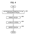
- Fig. 4 is a flowchart representing process procedures of the SLAM function performed by the autonomous moving apparatus according to a preferred embodiment of the present invention.
- Fig. 5 is a flowchart representing process procedures of the dead reckoning function performed by the autonomous moving apparatus according to a preferred embodiment of the present invention.
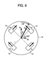
- Fig. 6 represents the relation between a travel amount and a rotation amount of the autonomous moving apparatus and an amount of wheel movement and a direction of each omni-wheel according to a preferred embodiment of the present invention.
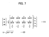
- Fig. 7 is a relational expression of the travel amount and the rotation amount of the autonomous moving apparatus and the amount of wheel movement and the direction of each omni-wheel according to a preferred embodiment of the present invention.
- Fig. 8 illustrates an example of a task selection screen according to a preferred embodiment of the present invention.
- Fig. 9 illustrates an example of a global map on which a moving obstacle is reflected according to a preferred embodiment of the present invention.
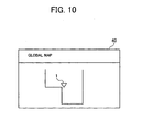
- Fig. 10 illustrates an example of the global map that has removed the moving obstacle according to a preferred embodiment of the present invention.
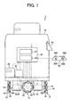
- FIG. 1 is a block diagram of the configuration of the autonomous moving apparatus 1.
- Fig. 2 illustrates a relation between a detection area 20A of a laser range finder 20 and an arrangement of a touch-screen display 40.
- the autonomous moving apparatus 1 can be manually moved/operated by operator's operations and can autonomously move/operate based on a self-judgment horizontally in all directions (by 360 degrees about the apparatus) and also in a pivoting manner around a center L1 of the apparatus.
- the autonomous moving apparatus 1 has a (SLAM) function of autonomously moving in the surrounding environment while simultaneously estimating a self-position and generating a global map.
- the autonomous moving apparatus 1 includes: a main body 10 provided with electric motors 12 and omni-wheels 13 that are driven by the electric motors 12, each of the motors 12 and the omni-wheels 13 being preferably arranged in a lower portion of the main body 10; a laser range finder 20 arranged to measure a distance between the apparatus 1 and an object (for example, walls and obstacles etc.) existed in the surroundings; an acceleration sensor 21 arranged to detect an inclination of the laser range finder 20; a touch-screen display 40 provided as a display unit and an input unit; and a joystick 50 provided as an operation unit for an operator 60 to manually move the autonomous moving apparatus 1.
- the autonomous moving apparatus 1 further includes an electronic control device 30.
- the electronic control device 30 is arranged to estimate the self-position and generate/update the global map based on a detection result of the laser range finder 20 when the laser range finder 20 is not inclined or when the inclination is constant, and arranged to stop the estimation of the self-position and the generation/update of the global map based on the detection result of the laser range finder 20 when the laser range finder 20 is inclined and when the inclination is not constant (i.e., when the inclination is changing).
- the electronic control device 30 is arranged to receive instructions from the operator 60 via the touch-screen display 40 and the joystick 50 and controls a display of the touch-screen display 40.
- the main body 10 is a metal frame having, but not limited to, a substantially cylindrical shape with a bottom, for example.
- the main body 10 includes the above laser range finder 20, the acceleration sensor 21, the electronic control device 30, and the touch-screen display 40 or the like.
- the omni-wheels 13 are attached to respective drive axes 12A of the four electric motors 12. In other words, the four omni-wheels 13 are preferably arranged on the same circumference with intervals of 90 degrees between each other along a circumferential direction.
- the omni-wheel 13 is a wheel that preferably includes two separate wheels 14 arranged to rotate about the drive axis 12A of the electric motor 12 and six free rollers 15 provided on an outer circumference of each of the wheels 14 in such a manner that the free rollers 15 can rotate about an axis that is perpendicular or substantially perpendicular to the drive axis of the electric motor 12.
- the omni-wheel 13 is thus capable of omnidirectional movement.
- the two wheels 14 are arranged with phases thereof shifted by 30 degrees. With the above configuration, when the electric motor 12 is driven, and the wheel 14 is resultantly rotated, the six free rollers 15 are rotated along with the wheel 14.
- the omni-wheel 13 By rotating the free roller 15 that is in contact with a ground, the omni-wheel 13 can also move in a direction that is parallel or substantially parallel with a rotational axis of the wheel 14. Therefore, by individually controlling the four electric motors 12, and by individually controlling a rotational direction and a rotational speed of each of the four omni-wheels 13, the autonomous moving apparatus 1 can horizontally move in a prescribed direction (in any desired direction) and can pivot about the center L1 of the apparatus.
- Each of the drive axes 12A of the four electric motors 12 is provided with an encoder 16 arranged to detect an angle of rotation (i.e., a drive amount or a rotation amount) of the corresponding drive axis 12A.
- Each of the encoders 16 is connected with the electronic control device 30 and outputs the detected rotation angle of each of the electric motors 12 to the electronic control device 30.
- the electronic control device 30 calculates a travel amount and direction of the autonomous moving apparatus 1 in accordance with the input rotation angle of each of the electric motors 12. A method of calculating the travel amount and direction of the autonomous moving apparatus 1 will be described later in detail.
- the encoders 16 and the electronic control device 30 function as a travel amount calculating unit.
- the laser range finder 20 is preferably attached to a front portion of the autonomous moving apparatus 1 to face a front direction of the apparatus. By outputting laser (a detection wave) and reflecting the output laser by a rotative mirror, the laser range finder 20 horizontally scans the surroundings of the autonomous moving apparatus 1. More specifically, as illustrated in Fig. 2 , the laser range finder 20 has a fan-like detection area 20A with a radius of four meters from the center L1 of the apparatus, and the fan-like detection area 20A spreads by 120 degrees positively and negatively from the front direction, which is set as a point of origin (0 degree).
- the laser range finder 20 detects the laser reflected by an object existed in the detection area 20A, measures a detection angle of the laser (reflected wave) and time (propagation time) from when the laser is output until when the laser is reflected by the object, and thus detects the angle with respect to the object and a distance between the apparatus 1 and the object.
- the laser range finder 20 functions as a distance information acquiring unit.
- the laser range finder 20 is connected with the electronic control device 30 and outputs distance information and angle information regarding the object detected in the surroundings to the electronic control device 30.
- the acceleration sensor 21 is preferably attached directly to the laser range finder 20 or to the vicinity of the laser range finder 20.
- the acceleration sensor 21 is arranged to output a voltage in accordance with a direction of a gravitational acceleration with respect to a detection axis, and detects an angle of inclination of the laser range finder 20 with respect to a horizontal plane, i.e., detects the inclination in front, back, right, and left directions. Therefore, the acceleration sensor 21 functions as an inclination detecting unit.
- Various types of acceleration sensors may be adopted, however, a capacitance sensor is used in the present embodiment as the acceleration sensor 21.
- the touch-screen display 40 is arranged to display, for example, the global map and various statuses of the autonomous moving apparatus 1. As illustrated in Fig. 2 , the touch-screen display 40 is preferably arranged on a rear surface side of the autonomous moving apparatus 1 and outside the fan-like detection area 20A of the above laser range finder 20 such that an operation displaying surface thereof faces the back direction, and that the display 40 slightly inclines backwards.
- the joystick 50 is an operation unit arranged to manually move the autonomous moving apparatus 1 and is connected with the electronic control device 30 via a cable having a prescribed length or via an interface (not illustrated).
- the joystick 50 preferably includes at least: a directional lever 50A arranged to input instructions for horizontally moving the autonomous moving apparatus 1 in the front, back, right, and left directions; a clockwise turning button 50B arranged to input instructions for turning the autonomous moving apparatus 1 rightward around the center L1 of the apparatus; a counter-clockwise turning button 50C arranged to input instructions for turning the autonomous moving apparatus 1 leftward around the center L1 of the apparatus; and a confirm button 50D arranged to input instructions for registering, for example, the self-position of the apparatus on the global map.
- the operator 60 stands on the rear surface side of the autonomous moving apparatus 1 and inputs the instructions using the touch-screen display 40 and the joystick 50 to the electronic control device 30.
- the autonomous moving apparatus 1 is provided, for example, with a setting mode in which the global map of the surrounding environment of the autonomous moving apparatus 1 is generated/updated and a moving mode in which the autonomous moving apparatus 1 moves to a destination based on a self-judgment, and the modes are switched when the operator 60 presses either a moving mode icon 40A or a setting mode icon 40B on a task selection screen ( Fig. 8 ) arranged on the touch-screen display 40.
- the operator 60 inputs a movement instruction using the joystick 50.
- the electronic control device 30 comprehensively controls the autonomous moving apparatus 1.
- the electronic control device 30 preferably includes: a micro processor arranged to perform calculations; a Read Only Memory (ROM) arranged to store programs etc. for executing various processes through the micro processor; a Random Access Memory (RAM) arranged to temporarily store various data such as calculation results; a backup RAM arranged to retain storage contents thereof using a battery.
- the electronic control device 30 further includes: an interface circuit arranged to electrically connect the laser range finder 20, the acceleration sensor 21, the touch-screen display 40, and the joystick 50 with the micro processor; and a driver circuit arranged to drive the electric motors 12, or the like.
- the electronic control device 30 moves the autonomous moving apparatus 1 in either the setting mode or the moving mode and implements a (SLAM) function of autonomously moving the apparatus in the surrounding environment while simultaneously estimating the self-position and generating the global map.
- the setting mode is defined as a mode in which the autonomous moving apparatus 1 generates/updates the global map of the surrounding environment for the autonomous movement through the SLAM function while the operator 60 uses the joystick 50 and the touch-screen display 40 to manually move the autonomous moving apparatus 1 horizontally in a pivoting manner.
- the moving mode is defined as a mode in which the autonomous moving apparatus 1 autonomously moves while checking the self-position and updating the global map through the SLAM function until the apparatus 1 arrives at a destination (goal) designated on the global map by the operator 60 through the touch-screen display 40.
- the electronic control device 30 implements a function of a self-position estimating unit 31 and a function of a global map generating unit 32.
- the self-position estimating unit 31 is arranged to estimate the self-position based on the distance information and the angle information both acquired by the laser range finder 20 and on the rotation angle of each of the electric motors 12 detected by the encoders 16.
- the global map generating unit 32 is arranged to generate the global map based on the distance information and the angle information both acquired by the laser range finder 20.
- the self-position estimating unit 31 When any of the setting mode and the moving mode is executed, and when the laser range finder 20 is not inclined, more specifically, when the inclination per unit of time does not change, the self-position estimating unit 31 generates a local map based on the distance information and the angle information regarding the object existed in the surroundings, which information is read (acquired) by the laser range finder 20, and then calculates the travel amount of the apparatus based on the rotation angle of each of the electric motors 12 read by the encoders 16. Thus, the self-position estimating unit 31 stochastically estimates the self-position using a Bayes' filter (Bayes' theorem) based on the generated local map and the travel amount of the apparatus.
- a Bayes' filter Bayes' theorem
- the self-position estimating unit 31 acquires a differential value (or a delta, i.e., the change of the inclination per unit of time) of the inclination of the laser range finder 20 detected by the acceleration sensor 21.
- a differential value or a delta, i.e., the change of the inclination per unit of time
- the self-position estimating unit 31 estimates the self-position as described above.
- the self-position estimation using the detection result of the laser range finder 20 is stopped, and the self-position is estimated based on the travel amount of the apparatus acquired from the rotation angle of each of the electric motors 12 (i.e., a dead reckoning process is executed).
- the electronic control device 30 (the self-position estimating unit 31) functions as a self-position estimating unit.
- the global map generating unit 32 When the laser range finder 20 is not inclined, the global map generating unit 32 performs a coordinate conversion on the local map that has the laser range finder 20 as the origin and that is generated by the self-position estimating unit 31, by adjusting the self-position from a coordinate system having the laser range finder 20 as the origin to a coordinate system of the global map, and thus reflects the local map onto the global map. Then, the global map generating unit 32 repeatedly executes the above process every control periods of the autonomous moving apparatus 1 (the electronic control device 30) and sequentially adds the local map to the global map to generate or update the global map of the entire surrounding environment.
- the global map generating unit 32 acquires the differential value (or the delta) of the inclination of the laser range finder 20.
- the process of generating/updating the global map is performed as described above.
- the differential value of the inclination of the laser range finder 20 is more than or equal to the prescribed value, i.e., when the inclination of the laser range finder 20 is changing, the process of generating/updating the global map using the detection results of the laser range finder 20 is stopped.
- the electronic control device 30 (the global map generating unit 32) functions as a global map generating unit.
- FIG. 3 is a flowchart representing procedures of a process of switching between the SLAM function and the dead reckoning function performed by the autonomous moving apparatus 1.
- Fig. 4 is a flowchart representing procedures of the SLAM process performed by the autonomous moving apparatus 1.
- Fig. 5 is a flowchart representing procedures of the dead reckoning process performed by the autonomous moving apparatus 1.
- Each of the processes represented in Figs. 3 through 5 is primarily performed by the electronic control device 30 and repeatedly executed every prescribed control periods (for example, every 200 milliseconds) from when a power of the autonomous moving apparatus 1 is turned on until when the power is turned off.
- the operator 60 touches the setting mode icon 40B to execute the setting mode.
- the moving mode icon 40A is touched, the moving mode is executed, and when a return icon 40C is touched, a previous screen is displayed. The process performed in the setting mode will be described below.
- step S100 Since the autonomous moving apparatus 1 is turning on the flat floor, the laser range finder 20 is not inclined, which indicates "NO" in the process of step S102, and thus the process proceeds to step S108, where the SLAM function of Fig. 4 is executed.
- the rotation angle of each of the electric motors 12 is read (step S200), and the local map is generated (step S202). Then, the self-position of the autonomous moving apparatus 1 is estimated based on the above information (step S204), and the local map is reflected onto the global map (step S206).
- the global map that is generated/updated every control periods is displayed every control periods in real time on the touch-screen display 40. Accordingly, even when a moving obstacle such as the feet of the operator 60 or of a passerby enters the detection area 20A of the laser range finder 20 and is detected, for example, and when such an obstacle is resultantly reflected onto the global map as a moving obstacle, because the operator 60 can confirm the obstacle on the touch-screen display 40, the operator 60 updates the global map without horizontally moving the autonomous moving apparatus 1, and thus can acquire the global map on which only fixed obstacles are reflected, i.e., the global map on which no moving obstacles are reflected.
- the inclination angle of the laser range finder 20 i.e., the inclination in the front, back, right, and left directions is read by the acceleration sensor 21 in step S100. Whether or not the laser range finder 20 is inclined is determined in step S102 based on the inclination angle read in step S100. When the laser range finder 20 is not inclined, the process proceeds to step S108. When the laser range finder 20 is inclined, the process proceeds to step S104, where the differential value (or the delta) of the inclination angle read in step S100 is calculated (step S104).
- step S104 determines whether or not the differential value of the inclination angle calculated in step S104 exceeds a prescribed threshold value (for example, 5 degrees/sec) in step S106.
- a prescribed threshold value for example, 5 degrees/sec
- the process proceeds to S108 where the SLAM function is executed in which the self-position is estimated based on the distance information and the angle information acquired by the laser range finder 20 and on the rotation angle of each of the electric motors 12 detected by the encoders 16, and the global map is generated based on the distance information and the angle information acquired by the laser range finder 20.
- step S110 the dead reckoning function is executed in which the self-position is estimated based on the travel amount of the apparatus acquired from the rotation angle of each of the electric motors 12.
- step S108 the SLAM function executed in step S108 and the dead reckoning function executed in step 110 will be described.
- the SLAM function implemented by the autonomous moving apparatus 1 will be described.
- the distance information and the angle information acquired by the laser range finder 20 regarding the obstacle existed in the surroundings and the rotation angle of each the electric motors 12 detected by the encoders 16 are read in step S200.
- step S202 the local map having the laser range finder 20 as the origin is generated based on the distance information and the angle information regarding the obstacle existed in the surroundings read in step S200, and the travel amount of the apparatus is calculated based on the rotation angle of each of the electric motors 12.
- Fig. 6 represents the relation between the travel amount and the amount of rotation of the autonomous moving apparatus 1 and the amount of wheel movement and the direction of each of the omni-wheels 13.
- Fig. 7 represents a relational expression of the travel amount and the rotation amount of the autonomous moving apparatus 1 and the amount of wheel movement and the direction of each of the omni-wheels 13.
- a distance from the center position of the four omni-wheels 13 to each of the omni-wheels 13 is defined as "L", and the inclination angle of the omni-wheel 13 is defined as " ⁇ ".
- the inclination angle " ⁇ " is set to 45°, and the amount of wheel movement of each of the omni-wheels 13 acquired from the rotation angle of the electric motor 12 is defined as "ci" ("i" ranges from 0 to 3).
- Each element (dx, dy) of the travel amount and the rotation angle " ⁇ " of the autonomous moving apparatus 1 can be acquired by a formula (1) of Fig. 7 .
- the travel amount "S" and the direction of the autonomous moving apparatus 1 can be acquired.
- the self-position can be stochastically acquired using the Bayes' filter based on the local map generated in step S202 and on the travel amount of the apparatus.
- step S206 a coordinate conversion is performed on the local map generated in step S202, by adjusting the self-position from a coordinate system having the laser range finder 20 as the origin to a coordinate system of the global map, the local map is reflected on the global map, and thus the global map of the entire surrounding environment can be generated or updated.
- the global map that is generated/updated every control periods is displayed in real time on the touch-screen display 40 every control periods. Therefore, even when a moving obstacle 61 such as a passerby enters the detection area 20A of the laser range finder 20, and when the moving obstacle 61 is detected and reflected on the global map as the moving obstacle ( Fig.
- the operator 60 can confirm the obstacle 61 on the touch-screen display 40, the operator 60 can generate or update the global map without horizontally moving the autonomous moving apparatus 1, or the operator 60 can generate or update the global map after confirming that the moving obstacle has departed from the detection area 20A, and then horizontally move the autonomous moving apparatus 1 .
- the global map on which only fixed obstacles are reflected i.e., the global map on which no moving obstacles are reflected ( Fig. 10 )
- the electronic control device 30 After returning to the process of S108, the electronic control device 30 once ends the above process.
- step S300 The rotation angle of each of the electric motors 12 detected by the encoders 16 is read in step S300.
- step S302 the travel amount of the apparatus is calculated based on the rotation angle of each of the electric motors 12 read in step S300, and the self-position is estimated based on the acquired travel amount of the apparatus.
- the method of acquiring the travel amount of the apparatus based on the rotation angle of each of the electric motors 12 has been described above, and the description thereof is omitted.
- the laser range finder 20 which acquires the distance information regarding the obstacle based on the propagation time of the output laser, is inclined, and when such inclination is changing, the self-position estimation and the generation of the global map based on the distance information acquired by the laser range finder 20 are stopped. Accordingly, when the autonomous moving apparatus 1 accelerates or decelerates, makes contact with an obstacle, or hurdles a bump or the like, and when the laser range finder 20 attached to the autonomous moving apparatus 1 resultantly oscillates, i.e., when there is a possibility of detecting a distance that is different from the distance detected in a normal state, the self-position estimation and the generation of the global map based on the distance information acquired by the laser range finder 20 are stopped.
- the estimation of the self-position and/or the generation of the global map using the detection result that is different from the correct detection result can be prevented.
- the reduction of the estimation accuracy of the self-position and the increase of errors in the generation of the global map, both arising from posture changes of the autonomous moving apparatus 1, can be suppressed.
- the self-position estimation and the global map generation based on the distance information acquired by the laser range finder 20 are executed. Therefore, in a situation where the autonomous moving apparatus 1 travels up a constantly-inclined slope, for example, the self-position estimation and the global map generation can be properly performed.
- the self-position is estimated based on the travel amount of the autonomous moving apparatus 1 acquired from the rotation angles (i.e., the amount of wheel movement) of the four omni-wheels 13. Therefore, even if the self-position estimation based on the distance information acquired by the laser range finder 20 is stopped, the self-position can be obtained.
- errors due to skids or the like accumulate in the self-position estimation performed through the dead reckoning function, an area in which the inclination of the laser range finder 20 changes is small in the entire global map. Therefore, the error accumulation is not significant, and the self-position can be obtained.
- the self-position estimation and the global map generation based on the distance information acquired by the laser range finder 20 are resumed.
- the self-position is estimated based on the travel amount of the autonomous moving apparatus 1 acquired based on a drive amount (i.e., the amount of wheel movement) of the four omni-wheels 13. Therefore, the self-position estimation and the global map generation can be continued from the position estimated based on the drive amount.
- the detection area 20A of the laser range finder 20 has the wide fan-like form with the radius of four meters, the area reflected from the local map acquired when the laser range finder 20 is oscillating can be covered by the area reflected from the local map that is acquired before/after the oscillation. Therefore, even if the global map generation is stopped when the oscillation occurs, there is only little influence. Moreover, even when the area reflected from the local map that could have been acquired at the time of oscillation is not updated, since the updating state of the global map can be confirmed on the touch-screen display 40, the not-yet updated area can be reliably updated by moving the autonomous moving apparatus 1 using the joystick 50 to the position that can be updated.
- the laser range finder has a high resolution and measurement accuracy in both the angular direction and the distance direction, and also can measure the distance between the apparatus and objects at high speed. Therefore, by measuring the distance between the apparatus and the object existed in the surroundings by the laser range finder 20 accurately at high speed, the self-position estimation and the global map generation can be performed with high accuracy at high speed.
- the present invention is not limited to the above embodiments and can be modified in various ways.
- the self-position estimation and the global map generation based on the distance information acquired by the laser range finder 20 are stopped.
- the self-position estimation and the global map generation based on the distance information acquired by the laser range finder 20 may be stopped whenever the laser range finder 20 is inclined.
- the present invention is applied to the autonomous moving apparatus 1 arranged to simultaneously estimate the self-position and generated the global map, however, the present invention may be applied to an apparatus that only estimates its self-position or to an apparatus that only generates a global map.
- the laser range finder 20 that uses the propagation time (i.e., using the "time propagation method") of the laser is adopted, however, other detection principles such as a laser range finder using a light path displacement etc. may be adopted. In place of the laser range finder using the laser, a distance sensor etc. using infrared light, for example, may be also adopted.
- the Bayes' filter is used when estimating the self-position, however, the self-position can be also estimated by using scan matching method such as an Iterative Closest Point (ICP) method, or the like.
- scan matching method such as an Iterative Closest Point (ICP) method, or the like.
- the distance information acquired by the laser range finder 20 is not used, however, a stereo camera or the like may be further provided, for example, and the distance between the apparatus and an object may be acquired by recognizing, through the stereo camera, the object detected by the laser range finder 20, and then correcting the inclination of the laser range finder 20 when it is determined that the same object (for example, the same wall surface) as the object detected in the non-oscillated state has been detected.
- the self-position estimation and the global map generation may be performed using the corrected distance information.
- the omni-wheels 13 capable of omnidirectional movement are used as the wheels, however, a normal wheel (such as a steering wheel and a drive wheel, for example) may also be used.
- a unit that detects the inclination of the laser range finder with respect to a floor surface (or the ground) on which the autonomous moving apparatus is traveling may be provided, and when it is determined from detection results of the unit that the laser range finder is inclined with respect to the floor surface (or the ground), the self-position estimation and/or the global map generation using the detection results of the laser range finder may be stopped.
Landscapes
- Engineering & Computer Science (AREA)
- Physics & Mathematics (AREA)
- Radar, Positioning & Navigation (AREA)
- Remote Sensing (AREA)
- Automation & Control Theory (AREA)
- General Physics & Mathematics (AREA)
- Aviation & Aerospace Engineering (AREA)
- Optics & Photonics (AREA)
- Electromagnetism (AREA)
- Human Computer Interaction (AREA)
- Robotics (AREA)
- Mechanical Engineering (AREA)
- Control Of Position, Course, Altitude, Or Attitude Of Moving Bodies (AREA)
Applications Claiming Priority (2)
| Application Number | Priority Date | Filing Date | Title |
|---|---|---|---|
| JP2008214871 | 2008-08-25 | ||
| JP2008297345A JP5141507B2 (ja) | 2008-08-25 | 2008-11-20 | 自律移動装置 |
Publications (2)
| Publication Number | Publication Date |
|---|---|
| EP2175337A2 true EP2175337A2 (fr) | 2010-04-14 |
| EP2175337A3 EP2175337A3 (fr) | 2014-06-11 |
Family
ID=41697126
Family Applications (1)
| Application Number | Title | Priority Date | Filing Date |
|---|---|---|---|
| EP09008090.4A Withdrawn EP2175337A3 (fr) | 2008-08-25 | 2009-06-19 | Appareil de déplacement autonome |
Country Status (4)
| Country | Link |
|---|---|
| US (1) | US8306684B2 (fr) |
| EP (1) | EP2175337A3 (fr) |
| JP (1) | JP5141507B2 (fr) |
| KR (1) | KR101380260B1 (fr) |
Cited By (2)
| Publication number | Priority date | Publication date | Assignee | Title |
|---|---|---|---|---|
| EP2804065A1 (fr) * | 2013-05-17 | 2014-11-19 | MSI Computer (Shenzhen) Co., Ltd. | Dispositif mobile pour générer une première information de carte pour un dispositif électronique et pour recevoir une deuxième information de carte du dispositif électronique |
| WO2018222253A1 (fr) * | 2017-05-31 | 2018-12-06 | Qualcomm Incorporated | Système et procédé de filtrage dynamique d'estimations de profondeur pour générer une carte volumétrique d'un environnement tridimensionnel présentant une profondeur maximale réglable |
Families Citing this family (77)
| Publication number | Priority date | Publication date | Assignee | Title |
|---|---|---|---|---|
| US10809071B2 (en) * | 2017-10-17 | 2020-10-20 | AI Incorporated | Method for constructing a map while performing work |
| US8996172B2 (en) | 2006-09-01 | 2015-03-31 | Neato Robotics, Inc. | Distance sensor system and method |
| KR101553653B1 (ko) * | 2009-01-07 | 2015-09-16 | 삼성전자 주식회사 | 로봇의 슬립 감지 장치 및 방법 |
| NZ598500A (en) * | 2009-08-31 | 2013-11-29 | Neato Robotics Inc | Method and apparatus for simultaneous localization and mapping of mobile robot environment |
| JP5451325B2 (ja) * | 2009-11-11 | 2014-03-26 | 鹿島建設株式会社 | バッテリーロコの前方監視方法 |
| JP5429986B2 (ja) * | 2009-12-25 | 2014-02-26 | 株式会社Ihiエアロスペース | 移動ロボットの遠方環境認識装置及び方法 |
| KR20110080322A (ko) * | 2010-01-05 | 2011-07-13 | 삼성전자주식회사 | 로봇의 슬립 감지 장치 및 방법 |
| JP5471626B2 (ja) * | 2010-03-09 | 2014-04-16 | ソニー株式会社 | 情報処理装置、マップ更新方法、プログラム及び情報処理システム |
| JP5588714B2 (ja) * | 2010-04-01 | 2014-09-10 | 株式会社ジー・イー・エヌ | 搬送台車システム |
| JP5503419B2 (ja) * | 2010-06-03 | 2014-05-28 | 株式会社日立製作所 | 無人搬送車および走行制御方法 |
| JP5560978B2 (ja) * | 2010-07-13 | 2014-07-30 | 村田機械株式会社 | 自律移動体 |
| JP5763986B2 (ja) * | 2011-06-30 | 2015-08-12 | 株式会社日立産機システム | 移動体および移動体の制御方法 |
| US8798840B2 (en) | 2011-09-30 | 2014-08-05 | Irobot Corporation | Adaptive mapping with spatial summaries of sensor data |
| US9453737B2 (en) * | 2011-10-28 | 2016-09-27 | GM Global Technology Operations LLC | Vehicle localization |
| KR20130068249A (ko) * | 2011-12-15 | 2013-06-26 | 한국전자통신연구원 | 이동체의 위치 추정 장치 및 방법 |
| KR101380852B1 (ko) * | 2012-05-30 | 2014-04-10 | 서울대학교산학협력단 | 사용자로부터 환경에 대한 사진 입력을 받는 이동로봇의 slam 시스템 및 방법 |
| US9183631B2 (en) * | 2012-06-29 | 2015-11-10 | Mitsubishi Electric Research Laboratories, Inc. | Method for registering points and planes of 3D data in multiple coordinate systems |
| US9420265B2 (en) | 2012-06-29 | 2016-08-16 | Mitsubishi Electric Research Laboratories, Inc. | Tracking poses of 3D camera using points and planes |
| JP6121663B2 (ja) * | 2012-07-10 | 2017-04-26 | 株式会社タダノ | 作業車両 |
| CN104487864B (zh) | 2012-08-27 | 2017-06-23 | 伊莱克斯公司 | 机器人定位系统 |
| US10448794B2 (en) | 2013-04-15 | 2019-10-22 | Aktiebolaget Electrolux | Robotic vacuum cleaner |
| KR20150141979A (ko) | 2013-04-15 | 2015-12-21 | 악티에볼라겟 엘렉트로룩스 | 돌출 측부 브러시를 구비하는 로봇 진공 청소기 |
| JP6136543B2 (ja) * | 2013-05-01 | 2017-05-31 | 村田機械株式会社 | 自律移動体 |
| JP6035209B2 (ja) * | 2013-07-11 | 2016-11-30 | ヤマハ発動機株式会社 | ナビゲーション装置、シミュレーション装置、移動装置およびナビゲーション方法 |
| EP3082542B1 (fr) * | 2013-12-19 | 2018-11-28 | Aktiebolaget Electrolux | Détection de gravissement d'obstacle d'un dispositif de nettoyage robotisé |
| US9946263B2 (en) | 2013-12-19 | 2018-04-17 | Aktiebolaget Electrolux | Prioritizing cleaning areas |
| EP3082537B1 (fr) | 2013-12-19 | 2020-11-18 | Aktiebolaget Electrolux | Dispositif de nettoyage robotisé et procédé de reconnaissance de point de repère |
| CN105792721B (zh) | 2013-12-19 | 2020-07-21 | 伊莱克斯公司 | 以螺旋样式移动的带侧刷的机器人真空吸尘器 |
| WO2015090403A1 (fr) | 2013-12-19 | 2015-06-25 | Aktiebolaget Electrolux | Commande de vitesse adaptative de brosse latérale rotative |
| KR102130190B1 (ko) | 2013-12-19 | 2020-07-03 | 에이비 엘렉트로룩스 | 로봇 청소 장치 |
| WO2015090402A1 (fr) | 2013-12-19 | 2015-06-25 | Aktiebolaget Electrolux | Dispositif de nettoyage robotisé à fonction d'enregistrement de périmètre |
| CN105848545B (zh) | 2013-12-20 | 2019-02-19 | 伊莱克斯公司 | 灰尘容器 |
| US20150202770A1 (en) * | 2014-01-17 | 2015-07-23 | Anthony Patron | Sidewalk messaging of an autonomous robot |
| JP6486024B2 (ja) | 2014-07-02 | 2019-03-20 | 三菱重工業株式会社 | 構造物の屋内監視システム及び方法 |
| WO2016005012A1 (fr) | 2014-07-10 | 2016-01-14 | Aktiebolaget Electrolux | Procédé de détection d'une erreur de mesure dans un dispositif de nettoyage robotisé |
| JP6443897B2 (ja) | 2014-09-08 | 2018-12-26 | アクチエボラゲット エレクトロルックス | ロボット真空掃除機 |
| WO2016037636A1 (fr) | 2014-09-08 | 2016-03-17 | Aktiebolaget Electrolux | Aspirateur robotisé |
| WO2016091291A1 (fr) | 2014-12-10 | 2016-06-16 | Aktiebolaget Electrolux | Utilisation d'un capteur laser pour la détection d'un type de sol |
| WO2016091320A1 (fr) | 2014-12-12 | 2016-06-16 | Aktiebolaget Electrolux | Brosse latérale et dispositif de nettoyage robotisé |
| EP3234714B1 (fr) | 2014-12-16 | 2021-05-12 | Aktiebolaget Electrolux | Feuille de route basée sur l'expérience pour un dispositif de nettoyage robotisé |
| EP3234713B1 (fr) | 2014-12-16 | 2022-06-15 | Aktiebolaget Electrolux | Procédé de nettoyage pour un dispositif de nettoyage robotisé |
| US9471062B1 (en) * | 2014-12-30 | 2016-10-18 | Daniel Theobald | Vehicle operating method and system |
| JP6743828B2 (ja) | 2015-04-17 | 2020-08-19 | アクチエボラゲット エレクトロルックス | ロボット掃除機およびロボット掃除機を制御する方法 |
| WO2017036532A1 (fr) | 2015-09-03 | 2017-03-09 | Aktiebolaget Electrolux | Système de dispositifs de nettoyage robotisés |
| JP6789624B2 (ja) * | 2015-11-20 | 2020-11-25 | キヤノン株式会社 | 情報処理装置、情報処理方法 |
| DE102016101552A1 (de) * | 2016-01-28 | 2017-08-03 | Vorwerk & Co. Interholding Gmbh | Verfahren zum Erstellen einer Umgebungskarte für ein selbsttätig verfahrbares Bearbeitungsgerät |
| US10662045B2 (en) | 2016-02-11 | 2020-05-26 | Clearpath Robotics Inc. | Control augmentation apparatus and method for automated guided vehicles |
| JP7035300B2 (ja) | 2016-03-15 | 2022-03-15 | アクチエボラゲット エレクトロルックス | ロボット清掃デバイス、ロボット清掃デバイスにおける、断崖検出を遂行する方法、コンピュータプログラム、およびコンピュータプログラム製品 |
| WO2017194102A1 (fr) | 2016-05-11 | 2017-11-16 | Aktiebolaget Electrolux | Dispositif de nettoyage robotisé |
| CN106125739A (zh) * | 2016-08-29 | 2016-11-16 | 深圳市劲拓自动化设备股份有限公司 | 一种基于多辆全向移动平台的联动控制系统及控制方法 |
| NL2017645B1 (en) | 2016-10-20 | 2018-04-26 | Lely Patent Nv | Animal farm system and method of generating barn map information of said animal farm system |
| EP3343431B1 (fr) * | 2016-12-28 | 2025-04-30 | Volvo Car Corporation | Procédé et système de localisation de véhicule à partir d'une image de caméra |
| WO2018191818A1 (fr) | 2017-04-18 | 2018-10-25 | Clearpath Robotics Inc. | Véhicule de transport de matériau autonome sans conducteur |
| JP6828579B2 (ja) * | 2017-04-27 | 2021-02-10 | トヨタ自動車株式会社 | 環境整備ロボットおよびその制御プログラム |
| US10459450B2 (en) | 2017-05-12 | 2019-10-29 | Autonomy Squared Llc | Robot delivery system |
| WO2018213931A1 (fr) | 2017-05-25 | 2018-11-29 | Clearpath Robotics Inc. | Systèmes et procédés d'orientation de processus au moyen d'un bras robotisé |
| WO2018219473A1 (fr) | 2017-06-02 | 2018-12-06 | Aktiebolaget Electrolux | Procédé de détection d'une différence de niveau d'une surface devant un dispositif de nettoyage robotisé |
| JP7087290B2 (ja) * | 2017-07-05 | 2022-06-21 | カシオ計算機株式会社 | 自律移動装置、自律移動方法及びプログラム |
| JP7061914B2 (ja) * | 2017-08-24 | 2022-05-02 | パナソニック インテレクチュアル プロパティ コーポレーション オブ アメリカ | 車両制御権設定方法、車両制御権設定装置、車両制御権設定プログラム及び車両制御方法 |
| WO2019041155A1 (fr) * | 2017-08-30 | 2019-03-07 | Qualcomm Incorporated | Navigation robuste d'un véhicule robotisé |
| WO2019041043A1 (fr) | 2017-08-31 | 2019-03-07 | Clearpath Robotics Inc. | Systèmes et procédés pour générer une mission pour un véhicule de transport de matériau à conduite autonome |
| WO2019063066A1 (fr) | 2017-09-26 | 2019-04-04 | Aktiebolaget Electrolux | Commande de déplacement d'un dispositif de nettoyage robotique |
| JP6635996B2 (ja) * | 2017-10-02 | 2020-01-29 | ソフトバンク株式会社 | 自律走行装置、自律走行システム及びプログラム |
| US20190120965A1 (en) * | 2017-10-25 | 2019-04-25 | Bae Systems Information And Electronic Systems Integration Inc. | Method and system of digital light processing and light detection and ranging for guided autonomous vehicles |
| WO2019084686A1 (fr) | 2017-10-31 | 2019-05-09 | Clearpath Robotics Inc. | Systèmes et procédés permettant de faire fonctionner un équipement robotique dans des zones contrôlées |
| WO2019090417A1 (fr) | 2017-11-10 | 2019-05-16 | Clearpath Robotics Inc. | Systèmes et procédés de mise à jour d'un plan électronique |
| US11592829B2 (en) | 2017-12-05 | 2023-02-28 | Sony Corporation | Control device and control method, program, and mobile object |
| US11453123B2 (en) * | 2017-12-27 | 2022-09-27 | Stmicroelectronics, Inc. | Robotic device with time-of-flight proximity sensing system |
| JP7081926B2 (ja) * | 2018-01-10 | 2022-06-07 | 株式会社日立製作所 | 移動体、動作制御システム、及び移動体システム |
| WO2020082120A1 (fr) * | 2018-10-22 | 2020-04-30 | Lazer Safe Pty Ltd | Système de surveillance/commande sans fil |
| KR102327209B1 (ko) * | 2018-11-20 | 2021-11-16 | 삼성전자주식회사 | 이동 장치 및 이동 장치에 부착된 거리 센서의 기울기를 감지하는 방법 |
| JP7275636B2 (ja) * | 2019-02-22 | 2023-05-18 | セイコーエプソン株式会社 | 無人搬送システム及び無人搬送車の自己位置推定方法 |
| KR102159048B1 (ko) * | 2019-12-26 | 2020-09-23 | 주식회사 폴라리스쓰리디 | 자율 주행 로봇의 스캔 경로 생성 방법 및 이를 수행하기 위한 컴퓨팅 장치 |
| US12122367B2 (en) | 2020-09-10 | 2024-10-22 | Rockwell Automation Technologies, Inc. | Systems and methods for operating one or more self-driving vehicles |
| JP7595744B2 (ja) * | 2021-03-11 | 2024-12-06 | 株式会社Fuji | 移動システム及び管理装置 |
| JP7595540B2 (ja) * | 2021-08-31 | 2024-12-06 | 三菱電機株式会社 | 計測装置、設備間距離計測システム、設備間距離計測方法および計測プログラム |
| CN121175636A (zh) * | 2023-05-11 | 2025-12-19 | 瑞典爱立信有限公司 | 停止生成环境的地图 |
Family Cites Families (12)
| Publication number | Priority date | Publication date | Assignee | Title |
|---|---|---|---|---|
| JPS61161523A (ja) | 1985-01-09 | 1986-07-22 | Matsushita Electric Ind Co Ltd | 移動体装置 |
| JP2769972B2 (ja) | 1994-03-10 | 1998-06-25 | 防衛庁技術研究本部長 | 不整地移動ロボットの自律走行システム |
| JP3945279B2 (ja) | 2002-03-15 | 2007-07-18 | ソニー株式会社 | 障害物認識装置、障害物認識方法、及び障害物認識プログラム並びに移動型ロボット装置 |
| JP2005103678A (ja) * | 2003-09-29 | 2005-04-21 | Toshiba Corp | ロボット装置 |
| US7689321B2 (en) * | 2004-02-13 | 2010-03-30 | Evolution Robotics, Inc. | Robust sensor fusion for mapping and localization in a simultaneous localization and mapping (SLAM) system |
| JP2006031642A (ja) | 2004-07-22 | 2006-02-02 | Ihi Aerospace Co Ltd | 移動体の自己位置特定方法 |
| JP2006136962A (ja) | 2004-11-11 | 2006-06-01 | Hitachi Ltd | 移動ロボット |
| JP4243594B2 (ja) | 2005-01-31 | 2009-03-25 | パナソニック電工株式会社 | 清掃ロボット |
| CA2918049C (fr) * | 2005-09-02 | 2019-04-09 | Neato Robotics, Inc. | Dispositif robotique multifonction |
| JP2007094743A (ja) | 2005-09-28 | 2007-04-12 | Zmp:Kk | 自律移動型ロボットとそのシステム |
| JP5188977B2 (ja) * | 2005-09-30 | 2013-04-24 | アイロボット コーポレイション | 個人の相互交流のためのコンパニオンロボット |
| KR100809352B1 (ko) * | 2006-11-16 | 2008-03-05 | 삼성전자주식회사 | 파티클 필터 기반의 이동 로봇의 자세 추정 방법 및 장치 |
-
2008
- 2008-11-20 JP JP2008297345A patent/JP5141507B2/ja active Active
-
2009
- 2009-02-04 KR KR1020090009032A patent/KR101380260B1/ko not_active Expired - Fee Related
- 2009-06-19 EP EP09008090.4A patent/EP2175337A3/fr not_active Withdrawn
- 2009-07-21 US US12/506,366 patent/US8306684B2/en active Active
Cited By (4)
| Publication number | Priority date | Publication date | Assignee | Title |
|---|---|---|---|---|
| EP2804065A1 (fr) * | 2013-05-17 | 2014-11-19 | MSI Computer (Shenzhen) Co., Ltd. | Dispositif mobile pour générer une première information de carte pour un dispositif électronique et pour recevoir une deuxième information de carte du dispositif électronique |
| US9357893B2 (en) | 2013-05-17 | 2016-06-07 | Msi Computer (Shenzhen) Co., Ltd. | Mobile device generating map information to an electronic device |
| CN104161487B (zh) * | 2013-05-17 | 2018-09-04 | 恩斯迈电子(深圳)有限公司 | 移动装置 |
| WO2018222253A1 (fr) * | 2017-05-31 | 2018-12-06 | Qualcomm Incorporated | Système et procédé de filtrage dynamique d'estimations de profondeur pour générer une carte volumétrique d'un environnement tridimensionnel présentant une profondeur maximale réglable |
Also Published As
| Publication number | Publication date |
|---|---|
| EP2175337A3 (fr) | 2014-06-11 |
| JP5141507B2 (ja) | 2013-02-13 |
| KR20100024335A (ko) | 2010-03-05 |
| JP2010079869A (ja) | 2010-04-08 |
| KR101380260B1 (ko) | 2014-04-01 |
| US20100049391A1 (en) | 2010-02-25 |
| US8306684B2 (en) | 2012-11-06 |
Similar Documents
| Publication | Publication Date | Title |
|---|---|---|
| US8306684B2 (en) | Autonomous moving apparatus | |
| EP1868056B1 (fr) | Appareil de déplacement, procédé, et support pour position de compensation de l'appareil de déplacement | |
| EP3168705B1 (fr) | Système robotique domestique | |
| US8897947B2 (en) | Autonomous mobile device | |
| JP5276931B2 (ja) | 移動体および移動体の位置推定誤り状態からの復帰方法 | |
| CN111164380B (zh) | 机器人的方位确定的方法、机器人的方位确定设备和机器人 | |
| JP4738472B2 (ja) | 障害物回避機能を有する移動制御装置 | |
| KR100772912B1 (ko) | 절대 방위각을 이용한 로봇 및 이를 이용한 맵 작성 방법 | |
| CN113454487B (zh) | 信息处理装置以及移动机器人 | |
| CN114355321B (zh) | 激光雷达的标定方法、装置、系统、激光雷达及机器人 | |
| CN111971633B (zh) | 位置推断系统、具有该位置推断系统的移动体以及记录介质 | |
| TWM477598U (zh) | 具有路線校正功能之移動裝置 | |
| Font-Llagunes et al. | Consistent triangulation for mobile robot localization using discontinuous angular measurements | |
| CN112697153B (zh) | 自主移动设备的定位方法、电子设备及存储介质 | |
| US20230419546A1 (en) | Online camera calibration for a mobile robot | |
| KR20220050483A (ko) | 무인 반송 차량의 위치 인식 장치 및 방법 | |
| WO2023192272A1 (fr) | Système de localisation hybride sensible au contexte pour véhicules terrestres | |
| JP5895682B2 (ja) | 障害物検出装置及びそれを備えた移動体 | |
| CN111736599A (zh) | 基于多激光雷达的agv导航避障系统、方法、设备 | |
| Shioya et al. | Minimal Autonomous Mover-MG-11 for Tsukuba Challenge– | |
| KR100784125B1 (ko) | 단일 카메라를 이용한 이동 로봇의 랜드 마크의 좌표 추출방법 | |
| JP6734764B2 (ja) | 位置推定装置、地図情報作製装置、移動体、位置推定方法及びプログラム | |
| Ibrayev et al. | Designing an Autonomous Mobile Robot Featuring Self-Localization through 3D LiDAR Technology | |
| TW201519842A (zh) | 具有路線校正功能之移動裝置及其作業步驟 | |
| CN119689496B (zh) | 机器人的位姿确定方法、机器人及存储介质 |
Legal Events
| Date | Code | Title | Description |
|---|---|---|---|
| PUAI | Public reference made under article 153(3) epc to a published international application that has entered the european phase |
Free format text: ORIGINAL CODE: 0009012 |
|
| AK | Designated contracting states |
Kind code of ref document: A2 Designated state(s): AT BE BG CH CY CZ DE DK EE ES FI FR GB GR HR HU IE IS IT LI LT LU LV MC MK MT NL NO PL PT RO SE SI SK TR |
|
| AX | Request for extension of the european patent |
Extension state: AL BA RS |
|
| PUAL | Search report despatched |
Free format text: ORIGINAL CODE: 0009013 |
|
| RIC1 | Information provided on ipc code assigned before grant |
Ipc: G05D 1/02 20060101AFI20140429BHEP |
|
| AK | Designated contracting states |
Kind code of ref document: A3 Designated state(s): AT BE BG CH CY CZ DE DK EE ES FI FR GB GR HR HU IE IS IT LI LT LU LV MC MK MT NL NO PL PT RO SE SI SK TR |
|
| AX | Request for extension of the european patent |
Extension state: AL BA RS |
|
| 17P | Request for examination filed |
Effective date: 20141023 |
|
| RBV | Designated contracting states (corrected) |
Designated state(s): AT BE BG CH CY CZ DE DK EE ES FI FR GB GR HR HU IE IS IT LI LT LU LV MC MK MT NL NO PL PT RO SE SI SK TR |
|
| STAA | Information on the status of an ep patent application or granted ep patent |
Free format text: STATUS: THE APPLICATION HAS BEEN WITHDRAWN |
|
| 18W | Application withdrawn |
Effective date: 20150430 |