EP2172960A2 - Korrektor von chromatischen Aberrationen für Ladungsträgerstrahlsystem und Korrekturverfahren dafür - Google Patents
Korrektor von chromatischen Aberrationen für Ladungsträgerstrahlsystem und Korrekturverfahren dafür Download PDFInfo
- Publication number
- EP2172960A2 EP2172960A2 EP09252365A EP09252365A EP2172960A2 EP 2172960 A2 EP2172960 A2 EP 2172960A2 EP 09252365 A EP09252365 A EP 09252365A EP 09252365 A EP09252365 A EP 09252365A EP 2172960 A2 EP2172960 A2 EP 2172960A2
- Authority
- EP
- European Patent Office
- Prior art keywords
- static
- chromatic aberration
- fold symmetry
- magnetic field
- optical axis
- Prior art date
- Legal status (The legal status is an assumption and is not a legal conclusion. Google has not performed a legal analysis and makes no representation as to the accuracy of the status listed.)
- Granted
Links
- 230000004075 alteration Effects 0.000 title claims abstract description 188
- 239000002245 particle Substances 0.000 title claims abstract description 31
- 238000000034 method Methods 0.000 title claims description 26
- 230000005405 multipole Effects 0.000 claims abstract description 161
- 230000003068 static effect Effects 0.000 claims abstract description 126
- 230000003287 optical effect Effects 0.000 claims abstract description 75
- 230000005672 electromagnetic field Effects 0.000 claims abstract description 63
- 201000009310 astigmatism Diseases 0.000 claims description 60
- 230000005684 electric field Effects 0.000 claims description 29
- 238000010894 electron beam technology Methods 0.000 abstract description 56
- 230000009471 action Effects 0.000 description 18
- 230000000694 effects Effects 0.000 description 11
- 230000005540 biological transmission Effects 0.000 description 6
- 238000005286 illumination Methods 0.000 description 4
- 230000004048 modification Effects 0.000 description 4
- 238000012986 modification Methods 0.000 description 4
- 238000010586 diagram Methods 0.000 description 3
- 230000007423 decrease Effects 0.000 description 2
- 230000001419 dependent effect Effects 0.000 description 2
- 150000002500 ions Chemical class 0.000 description 2
- 238000004519 manufacturing process Methods 0.000 description 2
- 230000009467 reduction Effects 0.000 description 2
- 206010010071 Coma Diseases 0.000 description 1
- 206010073261 Ovarian theca cell tumour Diseases 0.000 description 1
- 230000003190 augmentative effect Effects 0.000 description 1
- 230000008901 benefit Effects 0.000 description 1
- 230000002542 deteriorative effect Effects 0.000 description 1
- 238000007599 discharging Methods 0.000 description 1
- 238000009826 distribution Methods 0.000 description 1
- 230000001678 irradiating effect Effects 0.000 description 1
- 239000000463 material Substances 0.000 description 1
- 230000003071 parasitic effect Effects 0.000 description 1
- 230000035699 permeability Effects 0.000 description 1
- 208000001644 thecoma Diseases 0.000 description 1
Images


Classifications
-
- H—ELECTRICITY
- H01—ELECTRIC ELEMENTS
- H01J—ELECTRIC DISCHARGE TUBES OR DISCHARGE LAMPS
- H01J37/00—Discharge tubes with provision for introducing objects or material to be exposed to the discharge, e.g. for the purpose of examination or processing thereof
- H01J37/02—Details
- H01J37/04—Arrangements of electrodes and associated parts for generating or controlling the discharge, e.g. electron-optical arrangement, ion-optical arrangement
- H01J37/153—Electron-optical or ion-optical arrangements for the correction of image defects, e.g. stigmators
-
- H—ELECTRICITY
- H01—ELECTRIC ELEMENTS
- H01J—ELECTRIC DISCHARGE TUBES OR DISCHARGE LAMPS
- H01J37/00—Discharge tubes with provision for introducing objects or material to be exposed to the discharge, e.g. for the purpose of examination or processing thereof
- H01J37/02—Details
- H01J37/04—Arrangements of electrodes and associated parts for generating or controlling the discharge, e.g. electron-optical arrangement, ion-optical arrangement
- H01J37/10—Lenses
- H01J37/145—Combinations of electrostatic and magnetic lenses
-
- H—ELECTRICITY
- H01—ELECTRIC ELEMENTS
- H01J—ELECTRIC DISCHARGE TUBES OR DISCHARGE LAMPS
- H01J2237/00—Discharge tubes exposing object to beam, e.g. for analysis treatment, etching, imaging
- H01J2237/15—Means for deflecting or directing discharge
- H01J2237/151—Electrostatic means
- H01J2237/1516—Multipoles
-
- H—ELECTRICITY
- H01—ELECTRIC ELEMENTS
- H01J—ELECTRIC DISCHARGE TUBES OR DISCHARGE LAMPS
- H01J2237/00—Discharge tubes exposing object to beam, e.g. for analysis treatment, etching, imaging
- H01J2237/153—Correcting image defects, e.g. stigmators
- H01J2237/1534—Aberrations
Definitions
- the present invention relates to a chromatic and spherical aberration corrector for use in a charged particle beam system and to an aberration correction method for the system. More particularly, the invention relates to a chromatic and spherical aberration corrector using multipole elements making use of superimposed electric and magnetic fields for providing simultaneous correction of chromatic and spherical aberrations and to an aberration correction method therefor.
- spherical aberration and chromatic aberration are main factors deteriorating spatial resolution.
- an axisymmetric lens produces positive spherical aberration in essence and, therefore, it is impossible to produce a concave lens action from this lens.
- chromatic aberration it is impossible to remove the chromatic aberration using an axisymmetric lens. Therefore, rotationally symmetric fields produced by a multipole element are used to correct these aberrations.
- Non-patent documents 1 and 2 set forth a spherical aberration corrector using two stages of hexapole elements.
- This aberration corrector has a pair of transfer lenses, each consisting of an axisymmetric lens, and hexapole elements disposed at the nodal points of the transfer lenses at the opposite sides.
- the two stages of hexapole elements produce negative third-order spherical aberration.
- Spherical aberration in the whole system is removed by combining the hexapole elements with an objective lens.
- patent document 1 sets forth a chromatic aberration corrector in which electric field type quadrupoles and magnetic field type quadrupoles are combined.
- the chromatic aberration corrector has four stages of multipole elements.
- the first and fourth stages of multipole elements are electric field type quadrupole elements.
- the second and third stages of multipole elements have electric field type and magnetic field type quadrupole elements. That is, these multipole elements are of a so-called superimposed electric and magnetic field type.
- chromatic aberration corrector In this chromatic aberration corrector, chromatic aberration is corrected in the x-and y-directions independently if the optical axis is taken in the z-direction. Therefore, the correction produces a lens action which makes an electron beam diverge in one of the x- and y-directions and which converges the beam in the other. That is, so-called line focusing is achieved.
- the first stage of multipole element is mounted for the line focusing.
- this multipole element exerts a diverging action on the electron beam in the x-direction and a converging action in the y-direction
- the multipole element forms a linear electron beam extending in the x-direction in the center of the second stage of multipole element.
- the second stage of multiple element corrects chromatic aberration in the x-direction and, at the same time, produces a linear electron beam extending in the y-direction on the third stage of multipole element.
- the third stage of multipole element corrects chromatic aberration in the y-direction in the same way as the second stage of multipole element.
- the fourth stage of multipole element performs an operation reverse to line focusing, i.e., returns the linear electron beam to its original shape.
- the beam represents a reciprocal space image in the x-direction and a real space image in the y-direction.
- the electron beam represents a real space image in the x-direction and a reciprocal space image in the y-direction.
- the deflecting force exerted on the electron beam by an electric field type quadrupole is linearly proportional to the position of the beam within the multipole elements. Because the position of the beam in the reciprocal space image corresponds to the angle of incidence of the beam impinging on the first multipole element, it can be said that the deflecting force is linearly proportional to the angle of incidence. Furthermore, a similar principle applies to the deflecting force exerted on the beam by a magnetic field type quadrupole.
- the deflecting forces of the fields on the electron beam having a given energy can be made to cancel out each other by appropriately adjusting electric and magnetic fields produced by the electric field type quadrupole and magnetic field type quadrupole, respectively, in each of the second and third multipole elements.
- the obtained orbit is not different from a reference orbit assumed where aberrations are not taken into consideration.
- the refractive index of an electron beam i.e., dependence of the deflecting force on wavelength or on accelerating force
- the refractive index of the beam relative to a magnetic field is different from the refractive index of the beam relative to a magnetic field. Accordingly, where a deflecting force on the electron beam is canceled out by a combination of electric and magnetic fields, the beam does not deviate from the reference orbit. Only the refractive index relative to the electron beam varies on the orbit. Chromatic aberration can be corrected by setting a refractive index created by the magnetic and electric quadrupoles so as to cancel out the refractive index of the objective lens.
- an appropriate electron beam obtained by the above-described chromatic aberration corrector has a limited beam diameter for irradiating only small field of view. Therefore, the corrector can be introduced into a scanning electron microscope (SEM) or a scanning transmission electron microscope (STEM).
- SEM scanning electron microscope
- STEM scanning transmission electron microscope
- TEM transmission electron microscope
- this instrument cannot be used in TEM. Furthermore, if the electron beam is made to diverge excessively in one direction by line focusing, there is the danger that the beam collides against the inner wall of the vacuum vessel. If such a collision takes place, emission and scattering of electrons produce undesired noise. In addition, the degree of vacuum may be deteriorated uselessly.
- chromatic aberration corrector capable of correcting chromatic aberration and spherical aberration simultaneously for a charged particle beam having a large diameter without performing line focusing.
- a first embodiment of the present invention provides a chromatic aberration corrector which achieves the foregoing object and which is used to correct chromatic aberration in a charged particle beam.
- the chromatic aberration corrector has a first and a second multipole elements.
- the first multipole element has a first thickness along the optical axis of the charged particle beam and produces a first static electromagnetic field of two-fold symmetry.
- the second multipole element is mounted on the optical axis, has a second thickness along the optical axis, and produces a second static electromagnetic field of two-fold symmetry.
- the first and second static electromagnetic fields cancel out 2-fold astigmatism in the charged particle beam due to magnetic field while satisfying a condition given by 2 ⁇ f 2 t 2 ⁇ A e ⁇ 2 - A m ⁇ 2
- a e2 is the amount of two-fold astigmatism per unit length produced by an electric field quadrupole
- a m2 is the amount of two-fold astigmatism per unit length produced by a magnetic field quadrupole
- t is the length (thickness) of each multipole element taken in the direction of the beam
- f is the focal distance of the objective lens.
- a chromatic aberration corrector which is based on the chromatic aberration corrector of the first embodiment is further characterized in that a static electric or magnetic field of 4-fold symmetry is superimposed on the first multipole element and a static electric or magnetic field of 4-fold symmetry is superimposed on the second multipole element, because each of the 4-fold astigmatism produced by the first multipole element and the second multipole element are cancel out, respectively.
- a chromatic aberration corrector which is based on the chromatic aberration corrector of the first embodiment is further characterized in that a static electric or magnetic field of 3-fold symmetry is superimposed on the first multipole element and a static electric or magnetic field of 3-fold symmetry is superimposed on the second multipole element, because the static symmetric electric field of 2-fold symmetry and the symmetric magnetic field of 2-fold symmetry cancel out each other within the range given by the above-described formula as described previously.
- correction of a spherical aberration using the fields of 3-fold symmetry can be realized. Consequently, chromatic aberration and spherical aberration can be corrected at the same time.
- a chromatic aberration corrector associated with the first embodiment of the present invention may further include a third multipole element which is mounted on the optical axis, has a third thickness along the optical axis, and produces a third static electric or magnetic field of 3-fold symmetry.
- Another chromatic aberration corrector which is based on the chromatic aberration corrector of the first embodiment is further characterized in that a static electric or magnetic field of 4-fold symmetry is superimposed on the first multipole element, and a static electric or magnetic field of 4-fold symmetry is superimposed on the second multipole element, because the static symmetric electric field of 2-fold symmetry and the symmetric magnetic field of 2-fold symmetry cancel out each other within the range given by the above-described formula as described previously.
- correction of a spherical aberration using the fields of 4-fold symmetry can be realized. Consequently, chromatic aberration and spherical aberration can be corrected at the same time.
- Another chromatic aberration corrector associated with the first embodiment of the present invention may further include a third multipole element which is mounted on the optical axis, and has a third thickness along the optical axis, and produces a third static electric or magnetic field of 4-fold symmetry.
- Another chromatic aberration corrector associated with the another first embodiment of the present invention may further include a third multipole element and a fourth multipole element.
- the third multipole element which is mounted on the optical axis, and has a third thickness along the optical axis produces a third static electromagnetic field bysuperimposingstatic electromagneticfield of 2-fold symmetry and static electric or magnetic field of 4-fold symmetry.
- the fourth multipole element which is mounted on the optical axis, and has a fourth thickness along the optical axis produces a fourth static electromagnetic field by superimposing static electromagnetic field of 2-fold symmetry and static electric or magnetic field of 4-fold symmetry.
- a pair of first transfer lenses may be mounted between the multipole elements.
- a pair of second transfer lenses may be mounted between the multipole element adjacent to the objective lens of the charged particle beam system and the objective lens.
- the first and second thicknesses may be different.
- magnetic poles producing magnetic fields may be quadrupoles or dodecapoles.
- electrodes producing a static electric field for creating the first static electromagnetic field are disposed in a vacuum.
- Magnetic poles producing a static magnetic field for creating the first static electromagnetic field are disposed outside the vacuum.
- electrodes producing a static electric field for creating the second static electromagnetic field are disposed in the vacuum.
- Magnetic poles producing a static magnetic field for creating the second static electromagnetic field are disposed outside the vacuum.
- a second embodiment of the present invention provides a method of correcting chromatic aberration in a charged particle beam system. This method starts with producing a first static electromagnetic field of two-fold symmetry along the optical axis of a charged particle beam. A second static electromagnetic field of two-fold symmetry is produced along the optical axis.
- the first and second static electromagnetic fields cancel out 2-fold astigmatism in the charged particle beam due to magnetic field while satisfying a condition given by 2 ⁇ f 2 t 2 ⁇ A e ⁇ 2 - A m ⁇ 2
- a e2 is the amount of two-fold astigmatism per unit length produced by an electric field quadrupole
- a m2 is the amount of two-fold astigmatism per unit length produced by a magnetic field quadrupole
- t is the length (thickness) of each multipole element taken in the direction of the beam
- f is the focal distance of the objective lens.
- a method of correcting chromatic aberration which is based on the method of correcting chromatic aberration of the second embodiment is further characterized in that a static electric or magnetic field of 4-fold symmetry is superimposed on the first static electromagnetic field of two-fold symmetry and a static electric or magnetic field of 4-fold symmetry is superimposed on the second static electromagnetic field of two-fold symmetry, because each of the 4-fold astigmatism produced by the first static electromagnetic field of two-fold symmetry and the second static electromagnetic field of two-fold symmetry are cancel out, respectively.
- chromatic and spherical aberrations are corrected at the same time by superimposing a static electric or magnetic field of 3-fold symmetry on the first static electromagnetic field and superimposing a static electric or magnetic field of 3-fold symmetry on the second static electromagnetic field.
- a third static electric or magnetic field of 3-fold symmetry along the optical axis may be produced.
- chromatic and spherical aberrations are corrected simultaneously by superimposing a static electric or magnetic field of 4-fold symmetry on the first multipole element and superimposing a static electric or magnetic field of 4-fold symmetry on the second multipole element.
- a third static electric or magnetic field of 4-fold symmetry using a third multipole element which is mounted on the optical axis, and has a third thickness along the optical axis may be produced.
- a third static electromagnetic field and a fourth static electromagnetic field may be further produced.
- the third static electromagnetic field is produced by superimposing the static electromagnetic field of 2-fold symmetry and the electric or magnetic field of 4-fold symmetry using a third multipole element which is mounted on the optical axis, and has a third thickness along the optical axis.
- the fourth static electromagnetic field is produced by superimposing the static electromagnetic field of 2-fold symmetry and the electric or magnetic field of 4-fold symmetry using a fourth multipole element which is mounted on the optical axis, and has a fourth thickness along the optical axis.
- chromatic aberration can be corrected without performing line focusing. Therefore, spherical aberration can be corrected at the same time. Accordingly, the aberration corrector and method can be applied to correction of chromatic aberration and spherical aberration in a charged particle beam having a large beam diameter as used in TEM. Furthermore, the chromatic and spherical aberrations are corrected simultaneously with two or three stages of multipole elements. Consequently, the optical system can be simplified. Hence, the charged particle beam system can be miniaturized. This leads to a reduction in the manufacturing cost.
- the preferred embodiments of the present invention are hereinafter described with reference to the drawings.
- the invention can be applied to charged particles such as electrons, positrons, negative ions, or positive ions.
- the treated charged particle beam is assumed to be an electron beam, for the sake of convenience.
- the multipole element has a thickness is as follows. For example, a quadrupole element and a hexapole element fundamentally produce a symmetric field of 2-fold symmetry and a symmetric field of 3-fold symmetry, respectively. Where fields produced by the multipole elements are expanded with the multipole fields, the produced symmetric fields are referred to as primary terms. An actual multipole element produces quite weak fields by higher-order terms other than the primary terms. In a normal multipole element having no or little thickness, higher-order terms other than the primary terms are neglected in applications of the multipole elements or are merely parasitic factors. However, if the thickness of the multipole element is increased, the higher-order terms other than the primary terms manifest their effects. In order to make positive use of the effects, the multipole element is made to have a required length (or, thickness) along the optical axis. A field produced by the multipole element has a "thickness".
- the multipole element has a thickness t along the optical axis.
- 2n indicate a cylindrically symmetric lens action.
- Each term having the sign + indicates a concave lens action.
- 2(n-1) indicate two-fold astigmatism.
- has a proportional relationship given by A E ⁇ 2 ⁇ 1 U where U is an accelerating voltage.
- has a proportional relationship given by A B ⁇ 2 ⁇ 1 U
- of Eq. (1) are 2n and 2 (n - 1), respectively. If this is taken into consideration, the dependence of the deflecting force produced by the optical system on the accelerating voltage can be set so as to be in proportion to 1/U N (where N is a positive integer) by a combination of terms associated with the coefficient
- assumes a finite value for the electron beam accelerated by an accelerating voltage different from the given accelerating voltage. Accordingly, the beam undergoes a concave lens action.
- the deflecting force produced by this lens is generally given by 1 f ⁇ 1 U
- the dependence of the deflecting force produced by the quadrupole element having a thickness on accelerating voltage is given by 1/U N .
- the dependence of the accelerating voltage U given by Eq. (4) is given by 1/U. That is, they differ greatly in dependence on accelerating voltage. Therefore, the quadrupole field having a thickness is different in refractive index from the objective lens. It can be seen that this difference makes it possible to apply the concave lens action of the quadrupole field having a thickness to correction of chromatic aberration in the objective lens.
- the concave lens action of the two stages of quadrupole elements each having a thickness corrects chromatic aberration in the objective lens without producing two-fold astigmatism similarly to the description made with reference to Eqs. (2)-(4).
- the concave lens action increases with increasing the thickness t of each quadrupole element. Therefore, the thickness t can be set according to the required strength of the concave lens action.
- a 2m , t, r b , N, and I are two-fold astigmatism coefficient of the magnetic quadrupole element, thickness along the optical axis, bore radius, number of turns of the exciting coil on the quadrupole element, and value of electrical current flowing through the coil, respectively. That is, NI indicates a magnetomotive force.
- U is an accelerating voltage by which the electron beam is accelerated.
- e is an elementary electric charge.
- m is the mass of an electron.
- ⁇ 0 is the free space magnetic permeability.
- these magnetic quadrupole and electric quadrupole elements are combined in a field superimposed multipole element.
- this multipole element the deflecting force of the accelerating voltage U on the electron beam is somewhat or considerably canceled out.
- the orbit of the electron beam is mainly altered by the second term regarding two-fold astigmatism.
- the coefficient A 2 of this term satisfies Eqs. (6) and (7) and is given by the following relational formula.
- a 2 A e ⁇ 2 - A m ⁇ 2
- spherical aberration correction can be made using plural three-fold symmetric fields. That is, three-fold symmetric fields produced by plural hexapole elements described in non-patent document 2 produce negative spherical aberration. Consequently, positive spherical aberration in an objective lens can be canceled out. Accordingly, spherical and chromatic aberrations are corrected simultaneously by superimposing the three-fold symmetric fields on the superimposed electric and magnetic fields produced by the above-described multipole elements.
- the 6-fold astigmatism is a function of the 3-fold astigmatism. If the 3-fold astigmatism is rotated about the optical axis, the 6-fold astigmatism will be reduced. In consequence, it is possible to build an optical system that produces little 6-fold astigmatism while correcting spherical aberration. Because the electrode thickness can be increased, the voltage applied during chromatic aberration correction can be lowered. Electric field quadrupole elements used for chromatic aberration correction may be mounted on any two of the three stages of multipole elements.
- a method of correcting spherical aberration by making use of line focusing utilizes the following principle.
- the beam hardly undergoes the force from the superimposed fields in locations close to the optical axis.
- the electron beam undergoes to a larger extent the force from the fields created by the multipole element.
- a method to compensate for the 4-fold astigmatism is to make another aberration having the same magnitude and the opposite sign as that of the original aberration.
- At least three multipole elements are required since the method needs two sets of 4-fold astigmatism aberrations.
- the 4-fold astigmatism from the first and second multipole elements is eliminated by the negative astigmatism from the third and fourth multipole elements.
- the 4-fold astigmatism from the first and second multipole elements may be eliminated by the negative astigmatism from the second and third multipole elements.
- chromatic aberration can be corrected without performing line focusing. Therefore, spherical aberration can be corrected at the same time. Consequently, chromatic and spherical aberrations can be corrected simultaneously for a charged particle beam having a large beam diameter as used in TEM.
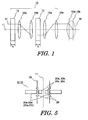
- Fig. 1 is a schematic ray diagram of a chromatic aberration corrector associated with one embodiment of the present invention.
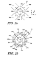
- Fig. 2a schematically illustrates the configuration of multipole elements in the chromatic aberration corrector shown in Fig. 1 , each of the multipole elements using superimposed electric and magnetic fields.
- this chromatic aberration corrector is used in a transmission electron microscope (TEM).
- the chromatic aberration corrector associated with one embodiment of the present invention is indicated by reference numeral 10 and has a first multipole element 12 and a second multipole element 13 arranged along the optical axis 11 of a charged particle beam.
- the second element 13 is located behind the first element 12.
- the first multipole element 12 has a thickness of t 1 along the direction of the optical axis and produces a first static electric field of 3-fold symmetry and a first static electromagnetic field of 2-fold symmetry superimposed on the first static electric field.
- the second multipole element 13 has a thickness of t 2 along the direction of the optical axis and produces a second static magnetic field of 3-fold symmetry and a second static electromagnetic field of 2-fold symmetry superimposed on the second static magnetic field.
- the chromatic aberration corrector 10 has transfer lenses of a pair (14a and 14b) mounted between the multipole elements 12 and 13 and having a transfer magnification of 1:1 and transfer lenses of a pair (15a and 15b) mounted between an objective lens 16 and the second multipole element 13 and having a transfer magnification of 1:1.
- Each of the multipole elements 12 and 13 has plural magnetic poles and electrodes regularly arranged around the optical axis 11.
- Fig. 2a shows one example of the multipole element 12.
- the multipole element 12 has quadrupolar electrodes 20a-20d and quadrupolar magnetic poles 30a-30d around the optical axis 11 extending in the direction of the Z-axis.
- the electrodes 20a-20d define a bore diameter r a .
- the magnetic poles 30a-30d define a bore diameter r b .
- the electrodes 20a-20d are angularly spaced at intervals of 90° on a plane (XY-plane) perpendicular to the optical axis 11. Voltages applied to the electrodes 20a-20d have the same absolute value but have alternating polarity. Because the applied voltages are so set as to satisfy Eq. (10), an electric field contributing to the first static electromagnetic field is produced. Since a magnetic field needs to be distributed around the optical axis 11, the electrodes 20a-20d are made of a nonmagnetic material.
- the magnetic poles 30a-30d are angularly spaced at intervals of 90° on a plane perpendicular to the optical axis 11.
- An exciting coil (not shown) having a number of turns N of wire is wound on a rear-end portion (not shown) of each of the magnetic poles 30a-30d.
- An electrical current I flows through the exciting coil. Accordingly, the magnetomotive force of each magnetic pole is NI.
- Each exciting coil is connected with a separate current source (not shown). The magnetomotive force is set at will. As shown in Figs. 6a and 6b , forces F E that the electron beam undergoes from an electric field quadrupole and forces F B that the beam undergoes from a magnetic field quadrupole are applied in such directions that the forces cancel out each other almost fully.
- the second multipole element 13 has electrodes and magnetic poles in the same way as the first multipole element 12.
- the electrodes and magnetic poles are physically arranged similarly to the configuration of Fig. 2a except that their polarities are reversed compared with the first multipole element 12. That is, when viewed from the optical axis 11, the polarities of the multipole element 13 have been rotated through 90° relative to the polarities of the multipole element 12 shown in Fig. 2a .
- the number of magnetic poles formed on each of the multipole elements 12 and 13 may be changed from 4 to 12.
- a 3-fold symmetric field can be superimposed on the electric field and magnetic field quadrupole elements.
- magnetic poles producing 2-fold symmetric fields are indicated by N and S poles.
- Magnetic poles producing 3-fold symmetric fields are indicated by N and S poles. That is, with respect to magnetic fields developed by the magnetic poles, a magnetic field producing a 2-fold symmetric field and a magnetic field producing a 3-fold symmetric field are combined into one.
- Each of the magnetic poles 31a-311 of the dodecapole (12 poles) is connected with a separate exciting coil (not shown) and a separate current source (not shown).
- each magnetic pole can produce a magnetomotive force separately. Consequently, 3-fold symmetric magnetic fields for correcting spherical aberration and a magnetic field distribution for correcting chromatic aberration can be produced more appropriately.
- the pair of transfer lenses 14a and 14b transfers a reciprocal space image of the electron beam 17 formed by the first multipole element 12 to the second multipole element 13.
- the pair of transfer lenses 14a and 14b are arranged for the following reason.
- the pair of transfer lenses 15a and 15b transfers the reciprocal space image of the electron beam 17 appearing in the second multipole element 13 to a coma-free plane 16a of the objective lens.
- This plane is substantially identical with the front focal plane of the objective lens.
- the reciprocal space image transferred to the coma-free plane 16a becomes a real space image at the specimen surface 16b of the objective lens. Because positive chromatic aberration and positive spherical aberration in the objective lens are canceled out by negative chromatic aberration and negative spherical aberration produced by the optical systems of the multipole elements 12 and 13, the real space image of the electron beam 17 on the specimen surface is affected neither by the chromatic aberration nor by the spherical aberration.
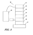
- Fig. 3 shows an example of transmission electron microscope (TEM) in which a chromatic aberration corrector of the present invention is used as an aberration corrector for the illumination system.
- the TEM indicated by 50, has an electron gun 51 that is made to produce an electron gun (not shown) under control of a high voltage control portion 58.
- the beam is accelerated to a desired energy.
- the accelerated beam is then focused by a first condenser lens 52.
- the focused beam passes through the aberration corrector 53 for the illumination system.
- the beam passed through the aberration corrector 53 is focused by a second condenser lens 54 and passes through an objective lens and specimen stage 55. A specimen is placed on the specimen stage.
- the electron beam transmitted through the specimen is magnified by an intermediate projector lens 56 and impinges on a fluorescent screen (not shown) on an observation chamber 57.
- the specimen image projected on the fluorescent screen is captured by a camera or other device.
- the objective lens When the beam passes through the objective lens and specimen stage 55, the objective lens further focuses the beam. At this time, positive spherical aberration in the objective lens operates to increase the diameter of the spot of the beam on the specimen surface. However, the positive spherical aberration is canceled out by the negative spherical aberration produced by the aberration corrector 53 for the illumination system. Action of increasing the diameter of the spot of the beam is also produced by the positive chromatic aberration in the objective lens. Also, in this case, the positive chromatic aberration in the objective lens is canceled out by the negative chromatic aberration produced by the aberration corrector 53 for the illumination system, in the same way as the foregoing. Accordingly, the electron beam that is affected neither by spherical aberration nor by chromatic aberration on the specimen surface illuminates a wide area, thus improving the spatial resolution.
- the chromatic aberration corrector of the present invention is installed in a charged particle beam system such as a SEM or STEM having an optical system similar to that of the TEM 50, an electron beam which has a quite small diameter and which suffers from a less amount of blur than conventional is obtained. Consequently, the spatial resolution is improved also in this case.
- the magnetic poles may be mounted outside a vacuum.
- Figs. 4a and 4b show examples in which the magnetic poles shown in Figs. 2a and 2b are mounted outside the vacuum.
- the electrodes 20a-20d are disposed inside a liner tube 25 through which the electron beam is transmitted, while the magnetic poles 30a-30f or 31a-311 are disposed outside the liner tube 25.
- electrical current introduction means 26 are mounted to maintain the vacuum inside the liner tube 25 and to permit application of voltages to the electrodes 20a-20d.
- the condition imposed on the first and second multipole elements 12 and 13 is given by Eq. (1). Therefore, as long as Eq. (10) is obeyed, the thicknesses t 1 and t 2 of the multipole elements may be different.
- the chromatic aberration corrector of the present invention is used for correction of chromatic aberration in the STEM mode of TEM or in SEM, it is not necessary to obtain a reciprocal space image over every direction (i.e., x- and y-directions as described already in the description of the related art) perpendicular to the optical axis 11. Consequently, at least one pair of the transfer lenses 14a, 14b and 15a, 15b described in the above embodiment may be omitted.
- the first and second static electromagnetic fields may be of 3-fold symmetry.
- the quadrupolar electrodes 20a-20d shown in Figs. 2a and 2b are replaced by hexapolar electrodes to produce a hexapolar electric field satisfying the requirement given by Eq. (10).
- a static magnetic field of 3-fold symmetry produced by the magnetic poles 30a-30f and satisfying Eq. (10) is superimposed on the hexapolar electric field.
- Magnetic poles and electrodes producing a static electromagnetic field of 2- or 3-fold symmetry for correcting chromatic aberration may be mounted on any two of the three stages of multipole elements.
- chromatic aberration can be corrected by producing a static electromagnetic field satisfying Eq. (10) by means of the multipole elements having the magnetic poles and electrodes producing the static electromagnetic field of 2- or 3-fold symmetry and superimposing the static magnetic field of 3-fold symmetry.
- spherical aberration can be corrected.
- the corrector can also be utilized in TEM if transfer lenses having a transfer magnification of 1:1 are mounted between the multipole elements. Additionally, similar transfer lenses may be mounted between the multipole element of the three stages of multipole elements which is adjacent to the objective lens and the objective lens.
- chromatic aberration is corrected while magnetic and electric deflecting forces exerted on the electron beam accelerated by the accelerating voltage U cancel out each other.
- spherical aberration can be corrected.
- the corrector can be applied to simultaneous correction of chromatic and spherical aberrations in a charged particle beam having a large beam diameter as used in TEM.
- the optical system is simplified because chromatic and spherical aberrations are corrected simultaneously by two or three stages of multipole elements. Accordingly, the charged particle beam system can be reduced in size. This leads to a reduction in the manufacturing cost.
Landscapes
- Chemical & Material Sciences (AREA)
- Analytical Chemistry (AREA)
- Electron Beam Exposure (AREA)
Applications Claiming Priority (1)
| Application Number | Priority Date | Filing Date | Title |
|---|---|---|---|
| JP2008259915 | 2008-10-06 |
Publications (3)
| Publication Number | Publication Date |
|---|---|
| EP2172960A2 true EP2172960A2 (de) | 2010-04-07 |
| EP2172960A3 EP2172960A3 (de) | 2012-01-04 |
| EP2172960B1 EP2172960B1 (de) | 2013-02-13 |
Family
ID=41467284
Family Applications (1)
| Application Number | Title | Priority Date | Filing Date |
|---|---|---|---|
| EP09252365A Active EP2172960B1 (de) | 2008-10-06 | 2009-10-06 | Korrektor von chromatischen Aberrationen für Ladungsträgerstrahlsystem und Korrekturverfahren dafür |
Country Status (3)
| Country | Link |
|---|---|
| US (1) | US8178850B2 (de) |
| EP (1) | EP2172960B1 (de) |
| JP (1) | JP5623719B2 (de) |
Cited By (4)
| Publication number | Priority date | Publication date | Assignee | Title |
|---|---|---|---|---|
| EP2388795A3 (de) * | 2010-05-18 | 2013-01-16 | JEOL Ltd. | Korrektor der sphärische Abberation und Verfahren zur Korrektur der sphärischen Abberation |
| EP3333877A1 (de) * | 2016-12-07 | 2018-06-13 | JEOL Ltd. | Einsatzrohr und elektronenmikroskop |
| EP3518269A1 (de) * | 2018-01-24 | 2019-07-31 | Jeol Ltd. | Vorrichtung zu aberrationskorrektur und elektronenmikroskop mit dieser vorrichtung |
| EP4030461A1 (de) * | 2020-12-31 | 2022-07-20 | FEI Company | Verminderung von thermischem magnetfeldrauschen in tem-korrektursystemen |
Families Citing this family (12)
| Publication number | Priority date | Publication date | Assignee | Title |
|---|---|---|---|---|
| EP2325862A1 (de) * | 2009-11-18 | 2011-05-25 | Fei Company | Korrektor für axiale Aberrationen einer teilchenoptischen Linse |
| EP2413345B1 (de) * | 2010-07-29 | 2013-02-20 | Carl Zeiss NTS GmbH | Strahlensystem mit geladenen Teilchen |
| WO2013077715A1 (ru) * | 2011-11-22 | 2013-05-30 | Bimurzaev Seitkerim Bimurzaevich | Корректор аберраций электронных линз |
| JP5934517B2 (ja) * | 2012-02-24 | 2016-06-15 | 日本電子株式会社 | 色収差補正装置及び色収差補正装置の制御方法 |
| US9275817B2 (en) | 2012-04-09 | 2016-03-01 | Frederick Wight Martin | Particle-beam column corrected for both chromatic and spherical aberration |
| US8541755B1 (en) * | 2012-05-09 | 2013-09-24 | Jeol Ltd. | Electron microscope |
| JP6054730B2 (ja) * | 2012-12-11 | 2016-12-27 | 日本電子株式会社 | 色収差補正装置および電子顕微鏡 |
| JP6009981B2 (ja) * | 2013-03-28 | 2016-10-19 | 日本電子株式会社 | 荷電粒子ビーム偏向装置 |
| JP6276101B2 (ja) | 2014-04-17 | 2018-02-07 | 日本電子株式会社 | 多極子レンズ、収差補正装置、および電子顕微鏡 |
| JP6324241B2 (ja) * | 2014-07-07 | 2018-05-16 | 株式会社日立ハイテクノロジーズ | 荷電粒子線装置および収差補正器 |
| RU185071U1 (ru) * | 2018-08-29 | 2018-11-20 | Российская Федерация, от имени которой выступает Государственная корпорация по атомной энергии "Росатом" (Госкорпорация "Росатом") | Устройство для фокусировки пучков ускоренных заряженных частиц на облучаемом объекте |
| JP6817349B2 (ja) * | 2019-01-29 | 2021-01-20 | 日本電子株式会社 | 偏向器および荷電粒子線装置 |
Citations (1)
| Publication number | Priority date | Publication date | Assignee | Title |
|---|---|---|---|---|
| JP2003203593A (ja) | 2001-10-26 | 2003-07-18 | Jeol Ltd | 荷電粒子ビーム装置における収差補正装置 |
Family Cites Families (12)
| Publication number | Priority date | Publication date | Assignee | Title |
|---|---|---|---|---|
| DE69026242T2 (de) * | 1990-04-12 | 1996-10-02 | Philips Electronics Nv | Korrekturvorrichtung für ein teilchengeladenes Strahlgerät |
| NL9100294A (nl) * | 1991-02-20 | 1992-09-16 | Philips Nv | Geladen deeltjesbundelinrichting. |
| DE19739290A1 (de) * | 1997-09-08 | 1999-03-11 | Ceos Gmbh | Verfahren zur Beseitigung axialer Bildfehler erster, zweiter und dritter Ordnung bei Korrektur des Öffnungsfehlers dritter Ordnung in elektronen-optischen Systemen |
| DE10001277A1 (de) * | 2000-01-14 | 2001-07-19 | Harald Rose | Elektronenoptischer Korrektor zur Beseitigung der Bildfehler dritter Ordnung |
| US6723997B2 (en) * | 2001-10-26 | 2004-04-20 | Jeol Ltd. | Aberration corrector for instrument utilizing charged-particle beam |
| JP4276929B2 (ja) * | 2003-11-18 | 2009-06-10 | 株式会社日立ハイテクノロジーズ | 荷電粒子線色収差補正装置および該収差補正装置を搭載した荷電粒子線装置 |
| JP4351108B2 (ja) * | 2004-04-07 | 2009-10-28 | 日本電子株式会社 | Semの収差自動補正方法及び収差自動補正装置 |
| JP2005353429A (ja) * | 2004-06-11 | 2005-12-22 | Hitachi Ltd | 荷電粒子線色収差補正装置 |
| JP2006278069A (ja) * | 2005-03-28 | 2006-10-12 | Jeol Ltd | ウィーンフィルタ型エネルギーアナライザ及び放出電子顕微鏡 |
| DE102005050810A1 (de) * | 2005-10-24 | 2007-04-26 | Ceos Gmbh | Elektronenoptischer Korrektor für aplanatische Abbildungssysteme |
| JP5069066B2 (ja) * | 2006-10-20 | 2012-11-07 | 日本電子株式会社 | 収差補正装置及び収差補正方法 |
| JP5226367B2 (ja) * | 2007-08-02 | 2013-07-03 | 日本電子株式会社 | 収差補正装置 |
-
2009
- 2009-09-15 JP JP2009212732A patent/JP5623719B2/ja active Active
- 2009-10-06 EP EP09252365A patent/EP2172960B1/de active Active
- 2009-10-06 US US12/573,973 patent/US8178850B2/en active Active
Patent Citations (1)
| Publication number | Priority date | Publication date | Assignee | Title |
|---|---|---|---|---|
| JP2003203593A (ja) | 2001-10-26 | 2003-07-18 | Jeol Ltd | 荷電粒子ビーム装置における収差補正装置 |
Non-Patent Citations (2)
| Title |
|---|
| H. ROSE, OPTIK, vol. 85, 1990, pages 19 - 24 |
| O. SCHERZER, OPTIK, vol. 2, 1947, pages 114 - 132 |
Cited By (4)
| Publication number | Priority date | Publication date | Assignee | Title |
|---|---|---|---|---|
| EP2388795A3 (de) * | 2010-05-18 | 2013-01-16 | JEOL Ltd. | Korrektor der sphärische Abberation und Verfahren zur Korrektur der sphärischen Abberation |
| EP3333877A1 (de) * | 2016-12-07 | 2018-06-13 | JEOL Ltd. | Einsatzrohr und elektronenmikroskop |
| EP3518269A1 (de) * | 2018-01-24 | 2019-07-31 | Jeol Ltd. | Vorrichtung zu aberrationskorrektur und elektronenmikroskop mit dieser vorrichtung |
| EP4030461A1 (de) * | 2020-12-31 | 2022-07-20 | FEI Company | Verminderung von thermischem magnetfeldrauschen in tem-korrektursystemen |
Also Published As
| Publication number | Publication date |
|---|---|
| EP2172960B1 (de) | 2013-02-13 |
| JP2010114068A (ja) | 2010-05-20 |
| US8178850B2 (en) | 2012-05-15 |
| US20100084567A1 (en) | 2010-04-08 |
| EP2172960A3 (de) | 2012-01-04 |
| JP5623719B2 (ja) | 2014-11-12 |
Similar Documents
| Publication | Publication Date | Title |
|---|---|---|
| EP2172960B1 (de) | Korrektor von chromatischen Aberrationen für Ladungsträgerstrahlsystem und Korrekturverfahren dafür | |
| EP1313125B1 (de) | Apparat für geladene Teilchen mit Aberrationskorrektur | |
| US6191423B1 (en) | Correction device for correcting the spherical aberration in particle-optical apparatus | |
| JP5660860B2 (ja) | 粒子光学レンズの軸収差用の補正装置 | |
| US6924488B2 (en) | Charged-particle beam apparatus equipped with aberration corrector | |
| US9349565B2 (en) | Multipole lens, aberration corrector, and electron microscope | |
| EP2020673A2 (de) | Aberrationskorrektursystem | |
| US6246058B1 (en) | Correction device for correcting chromatic aberration in particle-optical apparatus | |
| US8785880B2 (en) | Chromatic aberration corrector and electron microscope | |
| EP1432006B1 (de) | Energiefilter und Elektronenmikroskop | |
| JP2014022297A (ja) | 荷電粒子線装置 | |
| JP2004363045A (ja) | 荷電粒子ビーム装置における収差補正方法および荷電粒子ビーム装置 | |
| EP1914785B1 (de) | Aberrationskorrektor und Verfahren für Aberrationskorrektur | |
| US20080054186A1 (en) | Method of Aberration Correction and Electron Beam System | |
| JP4705812B2 (ja) | 収差補正装置を備えた荷電粒子ビーム装置 | |
| US20040000646A1 (en) | Array for achromatic imaging of a pulsed particle ensemble | |
| JP5069066B2 (ja) | 収差補正装置及び収差補正方法 | |
| JP4343951B2 (ja) | 荷電粒子ビーム系用の単段式荷電粒子ビームエネルギー幅低減系 | |
| JP2003502802A (ja) | 粒子レンズの色収差を除去する静電修正器 | |
| Martı́nez et al. | Design of Wien filters with high resolution | |
| EP1780762A1 (de) | Magnetenergiefilter | |
| EP3731255B1 (de) | Energiefilter und vorrichtung für geladene teilchenstrahlen | |
| JP2011091036A (ja) | 色収差補正ビーム偏向器、色収差補正ビーム分離器、荷電粒子デバイス、色収差補正ビーム偏向器を動作させる方法、及び色収差補正ビーム分離器を動作させる方法 | |
| JP2007242490A (ja) | 荷電粒子線光学系用の収差補正光学装置及び光学系 | |
| JP2007335385A (ja) | 収差補正荷電粒子ビーム発生装置 |
Legal Events
| Date | Code | Title | Description |
|---|---|---|---|
| PUAI | Public reference made under article 153(3) epc to a published international application that has entered the european phase |
Free format text: ORIGINAL CODE: 0009012 |
|
| AK | Designated contracting states |
Kind code of ref document: A2 Designated state(s): AT BE BG CH CY CZ DE DK EE ES FI FR GB GR HR HU IE IS IT LI LT LU LV MC MK MT NL NO PL PT RO SE SI SK SM TR |
|
| AX | Request for extension of the european patent |
Extension state: AL BA RS |
|
| PUAL | Search report despatched |
Free format text: ORIGINAL CODE: 0009013 |
|
| AK | Designated contracting states |
Kind code of ref document: A3 Designated state(s): AT BE BG CH CY CZ DE DK EE ES FI FR GB GR HR HU IE IS IT LI LT LU LV MC MK MT NL NO PL PT RO SE SI SK SM TR |
|
| AX | Request for extension of the european patent |
Extension state: AL BA RS |
|
| RIC1 | Information provided on ipc code assigned before grant |
Ipc: H01J 37/145 20060101ALI20111129BHEP Ipc: H01J 37/153 20060101AFI20111129BHEP |
|
| 17P | Request for examination filed |
Effective date: 20120704 |
|
| GRAP | Despatch of communication of intention to grant a patent |
Free format text: ORIGINAL CODE: EPIDOSNIGR1 |
|
| GRAS | Grant fee paid |
Free format text: ORIGINAL CODE: EPIDOSNIGR3 |
|
| GRAA | (expected) grant |
Free format text: ORIGINAL CODE: 0009210 |
|
| AK | Designated contracting states |
Kind code of ref document: B1 Designated state(s): AT BE BG CH CY CZ DE DK EE ES FI FR GB GR HR HU IE IS IT LI LT LU LV MC MK MT NL NO PL PT RO SE SI SK SM TR |
|
| REG | Reference to a national code |
Ref country code: GB Ref legal event code: FG4D |
|
| REG | Reference to a national code |
Ref country code: AT Ref legal event code: REF Ref document number: 596876 Country of ref document: AT Kind code of ref document: T Effective date: 20130215 |
|
| REG | Reference to a national code |
Ref country code: IE Ref legal event code: FG4D |
|
| REG | Reference to a national code |
Ref country code: DE Ref legal event code: R096 Ref document number: 602009013231 Country of ref document: DE Effective date: 20130411 |
|
| REG | Reference to a national code |
Ref country code: NL Ref legal event code: T3 |
|
| REG | Reference to a national code |
Ref country code: AT Ref legal event code: MK05 Ref document number: 596876 Country of ref document: AT Kind code of ref document: T Effective date: 20130213 |
|
| REG | Reference to a national code |
Ref country code: LT Ref legal event code: MG4D |
|
| PG25 | Lapsed in a contracting state [announced via postgrant information from national office to epo] |
Ref country code: AT Free format text: LAPSE BECAUSE OF FAILURE TO SUBMIT A TRANSLATION OF THE DESCRIPTION OR TO PAY THE FEE WITHIN THE PRESCRIBED TIME-LIMIT Effective date: 20130213 Ref country code: IS Free format text: LAPSE BECAUSE OF FAILURE TO SUBMIT A TRANSLATION OF THE DESCRIPTION OR TO PAY THE FEE WITHIN THE PRESCRIBED TIME-LIMIT Effective date: 20130613 Ref country code: SE Free format text: LAPSE BECAUSE OF FAILURE TO SUBMIT A TRANSLATION OF THE DESCRIPTION OR TO PAY THE FEE WITHIN THE PRESCRIBED TIME-LIMIT Effective date: 20130213 Ref country code: NO Free format text: LAPSE BECAUSE OF FAILURE TO SUBMIT A TRANSLATION OF THE DESCRIPTION OR TO PAY THE FEE WITHIN THE PRESCRIBED TIME-LIMIT Effective date: 20130513 Ref country code: LT Free format text: LAPSE BECAUSE OF FAILURE TO SUBMIT A TRANSLATION OF THE DESCRIPTION OR TO PAY THE FEE WITHIN THE PRESCRIBED TIME-LIMIT Effective date: 20130213 Ref country code: ES Free format text: LAPSE BECAUSE OF FAILURE TO SUBMIT A TRANSLATION OF THE DESCRIPTION OR TO PAY THE FEE WITHIN THE PRESCRIBED TIME-LIMIT Effective date: 20130524 Ref country code: BG Free format text: LAPSE BECAUSE OF FAILURE TO SUBMIT A TRANSLATION OF THE DESCRIPTION OR TO PAY THE FEE WITHIN THE PRESCRIBED TIME-LIMIT Effective date: 20130513 |
|
| PG25 | Lapsed in a contracting state [announced via postgrant information from national office to epo] |
Ref country code: PL Free format text: LAPSE BECAUSE OF FAILURE TO SUBMIT A TRANSLATION OF THE DESCRIPTION OR TO PAY THE FEE WITHIN THE PRESCRIBED TIME-LIMIT Effective date: 20130213 Ref country code: GR Free format text: LAPSE BECAUSE OF FAILURE TO SUBMIT A TRANSLATION OF THE DESCRIPTION OR TO PAY THE FEE WITHIN THE PRESCRIBED TIME-LIMIT Effective date: 20130514 Ref country code: PT Free format text: LAPSE BECAUSE OF FAILURE TO SUBMIT A TRANSLATION OF THE DESCRIPTION OR TO PAY THE FEE WITHIN THE PRESCRIBED TIME-LIMIT Effective date: 20130613 Ref country code: LV Free format text: LAPSE BECAUSE OF FAILURE TO SUBMIT A TRANSLATION OF THE DESCRIPTION OR TO PAY THE FEE WITHIN THE PRESCRIBED TIME-LIMIT Effective date: 20130213 Ref country code: FI Free format text: LAPSE BECAUSE OF FAILURE TO SUBMIT A TRANSLATION OF THE DESCRIPTION OR TO PAY THE FEE WITHIN THE PRESCRIBED TIME-LIMIT Effective date: 20130213 Ref country code: BE Free format text: LAPSE BECAUSE OF FAILURE TO SUBMIT A TRANSLATION OF THE DESCRIPTION OR TO PAY THE FEE WITHIN THE PRESCRIBED TIME-LIMIT Effective date: 20130213 Ref country code: SI Free format text: LAPSE BECAUSE OF FAILURE TO SUBMIT A TRANSLATION OF THE DESCRIPTION OR TO PAY THE FEE WITHIN THE PRESCRIBED TIME-LIMIT Effective date: 20130213 |
|
| PG25 | Lapsed in a contracting state [announced via postgrant information from national office to epo] |
Ref country code: HR Free format text: LAPSE BECAUSE OF FAILURE TO SUBMIT A TRANSLATION OF THE DESCRIPTION OR TO PAY THE FEE WITHIN THE PRESCRIBED TIME-LIMIT Effective date: 20130213 |
|
| PG25 | Lapsed in a contracting state [announced via postgrant information from national office to epo] |
Ref country code: EE Free format text: LAPSE BECAUSE OF FAILURE TO SUBMIT A TRANSLATION OF THE DESCRIPTION OR TO PAY THE FEE WITHIN THE PRESCRIBED TIME-LIMIT Effective date: 20130213 Ref country code: CZ Free format text: LAPSE BECAUSE OF FAILURE TO SUBMIT A TRANSLATION OF THE DESCRIPTION OR TO PAY THE FEE WITHIN THE PRESCRIBED TIME-LIMIT Effective date: 20130213 Ref country code: DK Free format text: LAPSE BECAUSE OF FAILURE TO SUBMIT A TRANSLATION OF THE DESCRIPTION OR TO PAY THE FEE WITHIN THE PRESCRIBED TIME-LIMIT Effective date: 20130213 Ref country code: SK Free format text: LAPSE BECAUSE OF FAILURE TO SUBMIT A TRANSLATION OF THE DESCRIPTION OR TO PAY THE FEE WITHIN THE PRESCRIBED TIME-LIMIT Effective date: 20130213 Ref country code: RO Free format text: LAPSE BECAUSE OF FAILURE TO SUBMIT A TRANSLATION OF THE DESCRIPTION OR TO PAY THE FEE WITHIN THE PRESCRIBED TIME-LIMIT Effective date: 20130213 |
|
| PLBE | No opposition filed within time limit |
Free format text: ORIGINAL CODE: 0009261 |
|
| STAA | Information on the status of an ep patent application or granted ep patent |
Free format text: STATUS: NO OPPOSITION FILED WITHIN TIME LIMIT |
|
| PG25 | Lapsed in a contracting state [announced via postgrant information from national office to epo] |
Ref country code: IT Free format text: LAPSE BECAUSE OF FAILURE TO SUBMIT A TRANSLATION OF THE DESCRIPTION OR TO PAY THE FEE WITHIN THE PRESCRIBED TIME-LIMIT Effective date: 20130213 |
|
| 26N | No opposition filed |
Effective date: 20131114 |
|
| REG | Reference to a national code |
Ref country code: DE Ref legal event code: R097 Ref document number: 602009013231 Country of ref document: DE Effective date: 20131114 |
|
| PG25 | Lapsed in a contracting state [announced via postgrant information from national office to epo] |
Ref country code: MC Free format text: LAPSE BECAUSE OF FAILURE TO SUBMIT A TRANSLATION OF THE DESCRIPTION OR TO PAY THE FEE WITHIN THE PRESCRIBED TIME-LIMIT Effective date: 20130213 |
|
| REG | Reference to a national code |
Ref country code: CH Ref legal event code: PL |
|
| REG | Reference to a national code |
Ref country code: IE Ref legal event code: MM4A |
|
| PG25 | Lapsed in a contracting state [announced via postgrant information from national office to epo] |
Ref country code: CH Free format text: LAPSE BECAUSE OF NON-PAYMENT OF DUE FEES Effective date: 20131031 Ref country code: LI Free format text: LAPSE BECAUSE OF NON-PAYMENT OF DUE FEES Effective date: 20131031 |
|
| REG | Reference to a national code |
Ref country code: FR Ref legal event code: ST Effective date: 20140630 |
|
| PG25 | Lapsed in a contracting state [announced via postgrant information from national office to epo] |
Ref country code: FR Free format text: LAPSE BECAUSE OF NON-PAYMENT OF DUE FEES Effective date: 20131031 |
|
| PG25 | Lapsed in a contracting state [announced via postgrant information from national office to epo] |
Ref country code: IE Free format text: LAPSE BECAUSE OF NON-PAYMENT OF DUE FEES Effective date: 20131006 |
|
| PG25 | Lapsed in a contracting state [announced via postgrant information from national office to epo] |
Ref country code: SM Free format text: LAPSE BECAUSE OF FAILURE TO SUBMIT A TRANSLATION OF THE DESCRIPTION OR TO PAY THE FEE WITHIN THE PRESCRIBED TIME-LIMIT Effective date: 20130213 |
|
| PG25 | Lapsed in a contracting state [announced via postgrant information from national office to epo] |
Ref country code: CY Free format text: LAPSE BECAUSE OF FAILURE TO SUBMIT A TRANSLATION OF THE DESCRIPTION OR TO PAY THE FEE WITHIN THE PRESCRIBED TIME-LIMIT Effective date: 20130213 Ref country code: TR Free format text: LAPSE BECAUSE OF FAILURE TO SUBMIT A TRANSLATION OF THE DESCRIPTION OR TO PAY THE FEE WITHIN THE PRESCRIBED TIME-LIMIT Effective date: 20130213 |
|
| PG25 | Lapsed in a contracting state [announced via postgrant information from national office to epo] |
Ref country code: HU Free format text: LAPSE BECAUSE OF FAILURE TO SUBMIT A TRANSLATION OF THE DESCRIPTION OR TO PAY THE FEE WITHIN THE PRESCRIBED TIME-LIMIT; INVALID AB INITIO Effective date: 20091006 Ref country code: MK Free format text: LAPSE BECAUSE OF FAILURE TO SUBMIT A TRANSLATION OF THE DESCRIPTION OR TO PAY THE FEE WITHIN THE PRESCRIBED TIME-LIMIT Effective date: 20130213 Ref country code: LU Free format text: LAPSE BECAUSE OF NON-PAYMENT OF DUE FEES Effective date: 20131006 |
|
| PG25 | Lapsed in a contracting state [announced via postgrant information from national office to epo] |
Ref country code: MT Free format text: LAPSE BECAUSE OF FAILURE TO SUBMIT A TRANSLATION OF THE DESCRIPTION OR TO PAY THE FEE WITHIN THE PRESCRIBED TIME-LIMIT Effective date: 20130213 |
|
| PGFP | Annual fee paid to national office [announced via postgrant information from national office to epo] |
Ref country code: NL Payment date: 20231019 Year of fee payment: 15 |
|
| PGFP | Annual fee paid to national office [announced via postgrant information from national office to epo] |
Ref country code: GB Payment date: 20231020 Year of fee payment: 15 |
|
| PGFP | Annual fee paid to national office [announced via postgrant information from national office to epo] |
Ref country code: DE Payment date: 20231020 Year of fee payment: 15 |