EP2163222A1 - Abutment mit Minimalkern - Google Patents
Abutment mit Minimalkern Download PDFInfo
- Publication number
- EP2163222A1 EP2163222A1 EP08016255A EP08016255A EP2163222A1 EP 2163222 A1 EP2163222 A1 EP 2163222A1 EP 08016255 A EP08016255 A EP 08016255A EP 08016255 A EP08016255 A EP 08016255A EP 2163222 A1 EP2163222 A1 EP 2163222A1
- Authority
- EP
- European Patent Office
- Prior art keywords
- abutment
- core
- cover layer
- oxide
- cores
- Prior art date
- Legal status (The legal status is an assumption and is not a legal conclusion. Google has not performed a legal analysis and makes no representation as to the accuracy of the status listed.)
- Granted
Links
Images




Classifications
-
- A—HUMAN NECESSITIES
- A61—MEDICAL OR VETERINARY SCIENCE; HYGIENE
- A61C—DENTISTRY; APPARATUS OR METHODS FOR ORAL OR DENTAL HYGIENE
- A61C8/00—Means to be fixed to the jaw-bone for consolidating natural teeth or for fixing dental prostheses thereon; Dental implants; Implanting tools
- A61C8/0012—Means to be fixed to the jaw-bone for consolidating natural teeth or for fixing dental prostheses thereon; Dental implants; Implanting tools characterised by the material or composition, e.g. ceramics, surface layer, metal alloy
- A61C8/0013—Means to be fixed to the jaw-bone for consolidating natural teeth or for fixing dental prostheses thereon; Dental implants; Implanting tools characterised by the material or composition, e.g. ceramics, surface layer, metal alloy with a surface layer, coating
- A61C8/0015—Means to be fixed to the jaw-bone for consolidating natural teeth or for fixing dental prostheses thereon; Dental implants; Implanting tools characterised by the material or composition, e.g. ceramics, surface layer, metal alloy with a surface layer, coating being a conversion layer, e.g. oxide layer
-
- A—HUMAN NECESSITIES
- A61—MEDICAL OR VETERINARY SCIENCE; HYGIENE
- A61C—DENTISTRY; APPARATUS OR METHODS FOR ORAL OR DENTAL HYGIENE
- A61C8/00—Means to be fixed to the jaw-bone for consolidating natural teeth or for fixing dental prostheses thereon; Dental implants; Implanting tools
- A61C8/0048—Connecting the upper structure to the implant, e.g. bridging bars
- A61C8/005—Connecting devices for joining an upper structure with an implant member, e.g. spacers
-
- A—HUMAN NECESSITIES
- A61—MEDICAL OR VETERINARY SCIENCE; HYGIENE
- A61C—DENTISTRY; APPARATUS OR METHODS FOR ORAL OR DENTAL HYGIENE
- A61C8/00—Means to be fixed to the jaw-bone for consolidating natural teeth or for fixing dental prostheses thereon; Dental implants; Implanting tools
- A61C8/0048—Connecting the upper structure to the implant, e.g. bridging bars
- A61C8/005—Connecting devices for joining an upper structure with an implant member, e.g. spacers
- A61C8/0053—Connecting devices for joining an upper structure with an implant member, e.g. spacers with angular adjustment means, e.g. ball and socket joint
-
- A—HUMAN NECESSITIES
- A61—MEDICAL OR VETERINARY SCIENCE; HYGIENE
- A61C—DENTISTRY; APPARATUS OR METHODS FOR ORAL OR DENTAL HYGIENE
- A61C8/00—Means to be fixed to the jaw-bone for consolidating natural teeth or for fixing dental prostheses thereon; Dental implants; Implanting tools
- A61C8/0048—Connecting the upper structure to the implant, e.g. bridging bars
- A61C8/005—Connecting devices for joining an upper structure with an implant member, e.g. spacers
- A61C8/0056—Connecting devices for joining an upper structure with an implant member, e.g. spacers diverging in the apical direction of the implant or abutment
-
- A—HUMAN NECESSITIES
- A61—MEDICAL OR VETERINARY SCIENCE; HYGIENE
- A61C—DENTISTRY; APPARATUS OR METHODS FOR ORAL OR DENTAL HYGIENE
- A61C8/00—Means to be fixed to the jaw-bone for consolidating natural teeth or for fixing dental prostheses thereon; Dental implants; Implanting tools
- A61C8/0048—Connecting the upper structure to the implant, e.g. bridging bars
- A61C8/005—Connecting devices for joining an upper structure with an implant member, e.g. spacers
- A61C8/0068—Connecting devices for joining an upper structure with an implant member, e.g. spacers with an additional screw
-
- A—HUMAN NECESSITIES
- A61—MEDICAL OR VETERINARY SCIENCE; HYGIENE
- A61C—DENTISTRY; APPARATUS OR METHODS FOR ORAL OR DENTAL HYGIENE
- A61C13/00—Dental prostheses; Making same
- A61C13/0003—Making bridge-work, inlays, implants or the like
- A61C13/0022—Blanks or green, unfinished dental restoration parts
Definitions
- the present invention relates to an abutment for a two-part dental implant.
- Two-piece dental implants are still very common.
- an anchoring part is implanted in a first step, on which the abutment is applied.
- an element to be applied such as a crown, bridge or prosthesis construction, is applied to the abutment.
- a straight, conical abutment has at the bottom a threaded stem which is screwed into the internal threaded bore present in the implant.
- the conical root part of the abutment then sits in the conical receiving bore and the head part of the abutment projects beyond the implant shoulder.
- the object of the present invention is therefore to provide a warning system that the dentist on it indicates that further abrasion of the abutment could result in fracture under load.
- the present invention relates to an abutment for attachment to a two-part implant.
- the abutment serves to receive another element to be applied.
- Such an element to be applied is for example an intermediate piece or a crown, bridge or prosthesis construction.
- the abutment has at least one core and one cover layer, wherein the at least one core and the cover layer are visually and / or acoustically different from one another.
- the at least one core is the part of the abutment that is minimally needed to ensure sufficient stability of the implant.
- the minimum diameter depends on the indication, the material and the processing.
- the cover layer represents an optional layer with respect to the stability of the implant, which may optionally be completely abraded.
- the thickness of the cover layer is chosen so that in a standard implantation as little as possible must be sanded so as not to unnecessarily prolong the patient visit.
- the dentist uses an abutment with an integrated warning system, which points him during the grinding of the abutment that the stability would not be guaranteed in a further grinding.
- cover layer is visually distinguishable from the at least one core.
- visual is meant that the difference between the cover layer and the at least one core is visible to the naked eye. This can be, for example, a different color or slightly different color shade.
- the at least one core is acoustically distinguishable from the cover layer.
- the term "acoustically” is understood to mean that the sound of the drill differs during abrading of the abutment, depending on whether the at least one core or cover layer is ground, the difference being so clear that the dentist perceives it immediately.
- the acoustically audible difference is created by the at least one core having a hardness different from the cover layer. Once the drill hits the harder material, the audible noise is higher than before,
- alumina Al 2 O 3
- Aluminum oxide is a transparent ceramic and is therefore suitable for aesthetic reasons for the top layer.
- the material used for the at least one core is preferably partially stabilized, polycrystalline tetragonal zirconia (Tetragonal zirconia polycrystal, TZP), in particular yttrium-stabilized TZP (Y-TZP). This material is characterized by an optimal behavior in terms of hardness and resistance to breakage, which is of course particularly important for the core.
- At least one core and the cover layer differ both visually and acoustically from one another, ie the dentist even has a double warning system. This can be achieved, for example, by adding color pigments and reinforcing the core material.
- abutment By grinding the abutment, either a straight or an angled abutment can be made.
- an abutment according to the invention with exactly one core and one covering layer is preferably used.
- the abutment according to the invention contains three or more cores and a cover layer, which are visually distinguishable from one another. This means that the at least three cores all have different colors or color nuances and additionally differ from the top layer. With such an abutment, preferably angled abutments are produced.
- the abutment according to this preferred embodiment now allows a maximum Einfgenautechnik, since the corresponding body part is ground after insertion by the dentist in situ in the mouth. The dentist receives clear guidelines as to how far he can grind through the three given cores.
- These three or more cores are preferably arranged at an inclination angle of 5 ° to 25 ° away from the central axis. In a preferred embodiment, the angle of inclination is 15 °.
- a threaded or unthreaded opening may be centrally located between the cores to secure a crown, bridge or denture construction thereon.
- the inventive abutment is preferably made of a biocompatible ceramic.
- the biocompatible ceramic is preferably a stabilized zirconium oxide ceramic, particularly preferably 92.1 to 93.5% by weight ZrO 2 and 4.5 to 5.5% by weight Y 2 O 3 and 1.8 by weight to 2.2.% HfO2.
- a stabilized zirconium oxide ceramic has an extraordinarily high mechanical stability and strength, in particular when produced by hot isostatic pressing or by sintering with subsequent hot isostatic densification.
- the cover layer can be sprayed onto the at least one core, which differs visually and / or acoustically from the cover layer and the blank thus obtained are sintered.
- an intermediate layer which has the function of a transition layer is provided between the at least one core and the cover layer. That either it has one of the cover layer and the at least one core different color or it has a hardness which is between the hardness of the cover layer and the hardness of the at least one core.
- the two-part implant to which the abutment according to the invention is applied, may be made of metal or a metal alloy, or of a ceramic.
- the implant is preferably made of titanium or a titanium alloy.
- the two-part implant is treated by a suitable abrading pretreatment or by a suitable coating on its outer surface so as to achieve good composite osteogenesis after implantation.
- the anchoring part may, for example, be silanized or hydroxylated on its surface. It is particularly preferably roughened by a removal method and etched with hydrofluoric acid.
- the implant has a in the EP 07 007 950.4 surface structure described, to which reference is made.
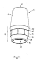
- the Konuspartie 15 has a mating contour 25 which is complementary to the receiving contour located in the implant, so that the abutment 5 can be used secured against rotation in the implant.
- the counter contour 25 is designed in this example as a polygon.
- the mating contour 25 is arranged on the Konuspartie 15 that here also uninterrupted segments 29, 30 of Konuspartie 15 are maintained. The lateral surfaces of both segments 29, 30 are aligned with each other, as well as the portions of the inner cone in the implant head of the two-part implant are aligned. In the transitions from the segment 29 to the mating contour 25 and last to the segment 30 paragraphs 45 arise. At the bottom, the abutment 5 and its segment ends with the outlet 50. It is also possible to arrange the mating contour 25 directly adjacent to the outlet.
- Fig. 2 shows a section through the in Fig. 1 shown abutment 5.
- a female thread portion beginning above 55 may be provided, and in front of the lower mouth of the inlet 20, there is a radially encircling groove 60.
- the possible female threaded portion 55 would serve to receive an occlusal screw, with which the superstructure are attached could.
- the grub screw of the Occlusal screw extends only partially into the inlet 20.
- a threadless screw head section 65 remains between the internal thread section 55 and the groove 60.
- the abutment 5 according to the invention has a core 75 and a cover layer 70 which are visually and / or acoustically different from one another.
- the dentist has the ability to grind the abutment 5, without having to worry that the stability of the implant after grinding of the abutment 5 is no longer guaranteed, since it is indicated by the color change or the acoustically perceptible change in the Bohrge Hursches when he can not continue grinding.
- Fig. 3 shows a section of the first embodiment of the inventive abutment 5, which has been attached to a two-piece implant 80 implanted in the jaw.
- the two-piece implant 80 is implanted in the bone tissue 85.
- the original shape of the abutment 5 is indicated by a line.
- the ground abutment 5 corresponds to the individual needs of the patient and ensures optimal stability of the implant.
- the core 75 which differs visually or acoustically from the cover layer 70, was not ground.
- the ground abutment 5 was supplied with a crown 90.
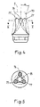
- Fig. 4 shows a second embodiment of the inventive abutment 5.
- the abutment 5 has three cores 75, 76, 77 and a cover layer 70, optionally between the cores 75, 76, 77 and the cover layer 70 may be arranged an intermediate layer can.
- the three cores 75, 76, 77 of the abutment are arranged with respect to the central axis of rotation axis symmetrical and with an inclination angle ⁇ of 5 to 25 °. Particularly preferred is an inclination angle ⁇ of 15 °.
- an opening 95 may be arranged, which serves for the attachment of a prosthetic element.
- Fig. 5 shows a section through the in Fig. 4 _ Abutment 5 shown to better illustrate the three cores 75, 76, 77.
- the three cores 75, 76, 77 allow a dentist to grind an angled abutment in a difficult jaw position, such as a jaw bone angled with respect to the cutting surface of the teeth. This is done without having to maintain the 360 ° angle otherwise required for prefabricated angled abutments in order to position the abutment in the correct position.
- Such an abutment 5 after the corresponding grinding is in FIG. 6 shown.
- an opening 95 may be arranged, which serves to attach the prosthetic elements.
- Fig. 7 shows a section of the second embodiment of the invention abertments abutments 5, which has been attached to a jaw-implanted two-piece implant 80.
- the two-piece implant 80 is implanted in the bone tissue 85.
- the original shape of the abutment 5 is indicated by a line.
- the ground angled abutment 5 corresponds to the individual needs of the patient and ensures optimal stability of the implant.
- the core 75 which differs visually or acoustically from the cover layer 70, was not ground.
- the ground abutment 5 was with supplied a crown 90.
Landscapes
- Health & Medical Sciences (AREA)
- Oral & Maxillofacial Surgery (AREA)
- Orthopedic Medicine & Surgery (AREA)
- Dentistry (AREA)
- Epidemiology (AREA)
- Life Sciences & Earth Sciences (AREA)
- Animal Behavior & Ethology (AREA)
- General Health & Medical Sciences (AREA)
- Public Health (AREA)
- Veterinary Medicine (AREA)
- Engineering & Computer Science (AREA)
- Ceramic Engineering (AREA)
- Dental Prosthetics (AREA)
Abstract
Description
- Die vorliegende Erfindung betrifft ein Abutment für ein zweiteiliges Dentalimplantat.
- Zweiteilige Dentalimplantate sind nach wie vor sehr verbreitet. Bei ihnen wird in einem ersten Schritt ein Verankerungsteil implantiert, auf welches das Abutment aufgebracht wird. Auf das Abutment wiederum wird ein zu applizierendes Element, wie eine Kronen-, Brücken- oder Prothesenkonstruktion aufgebracht.
- In der einfachsten Form weist ein gerades, konisches Abutment zuunterst einen Gewindezapfen auf, der in die im Implantat vorhandene Innengewindebohrung eingedreht wird. Die konische Wurzelpartie des Abutments sitzt dann in der konischen Aufnahmebohrung und das Kopfteil des Abutments überragt die Implantatschulter.
- Aufgrund der Kiefergegebenheiten oder wegen eines schräg gebohrten Bohrloches kann es jedoch auch notwendig sein, dass ein abgewinkeltes Abutment eingesetzt wird.
- Auch bei einer noch so guten Implantation eines Implantates ist es unumgänglich, dass grössere oder kleinere Korrekturen durch Beschleifen des Abutments vorgenommen werden müssen, um sicher zu stellen, dass die darauf aufgesetzten Prothetikelemente gut passen. Das Beschleifen des Abutments kann jedoch zur Folge haben, dass dieses Abutment stellenweise zu dünn wird, was vom Zahnarzt visuell schwer feststellbar ist. Dadurch ist die Gesamtstabilität nicht mehr gewährleistet, was unter Belastung zu einem Bruch führen kann.
- Aufgabe der vorliegenden Erfindung ist es somit, ein Warnsystem bereitzustellen, das den Zahnarzt darauf hinweist, dass eine weitere Beschleifung des Abutments zu einem Bruch unter Belastung führen könnte.
- Die Aufgabe wird gelöst durch ein Abutment gemäss Anspruch 1, Weitere bevorzugte Ausführungsformen sind Gegenstand der abhängigen Ansprüche 2 bis 17.
- Die vorliegende Erfindung betrifft ein Abutment zur Befestigung auf ein zweiteiliges Implantat. Das Abutment dient dazu, ein weiteres zu applizierendes Element aufzunehmen. Ein solches zu applizierendes Element ist beispielsweise ein Zwischenstück oder eine Kronen-, Brücken- oder Prothesenkonstruktion. Das Abutment weist wenigstens einen Kern und eine Deckschicht auf, wobei der wenigstens eine Kern und die Deckschicht visuell und/oder akustisch voneinander verschieden sind. Der wenigstens eine Kern ist dabei der Teil des Abutments, der minimal benötigt wird, um eine ausreichende Stabilität des Implantates zu gewährleisten. Der minimale Durchmesser hängt dabei von der Indikation, des Materials und der Verarbeitung ab. Im Gegensatz dazu stellt die Deckschicht bezüglich der Stabilität des Implantates eine optionale Schicht dar, die gegebenenfalls vollständig abgeschliffen werden darf. Idealerweise wird die Dicke der Deckschicht so gewählt, dass bei einer Standardimplantation möglichst wenig abgeschliffen werden muss, um die Patientenvisite nicht unnötig zu verlängern. Dadurch, dass der wenigstens eine Kern und die Deckschicht visuell und/oder akustisch voneinander unterscheidbar sind, setzt der Zahnarzt ein Abutment mit einem integrierten Warnsystem ein, das ihn beim Beschleifen des Abutments darauf hinweist, dass bei einem Weiterschleifen die Stabilität nicht mehr gewährleistet wäre.
- Dabei gibt es verschiedene Möglichkeiten, um sicherzustellen, dass die Deckschicht visuell von dem wenigstens einen Kern zu unterscheiden ist. Unter dem Ausdruck "visuell" wird verstanden, dass der Unterschied zwischen der Deckschicht und dem wenigstens einen Kern von blossem Auge erkennbar ist. Dies kann beispielsweise eine unterschiedliche Farbe oder leicht abweichende Farbnuance sein.
- Beispielsweise kann der wenigstens eine Kern Farbpigmente enthalten, die nicht oder in anderer Menge in der Deckschicht vorhanden sind. Solche Farbpigmente werden vorzugsweise aus der Gruppe bestehend aus Eisenoxid (Fe2O3), Eisennitrat (Fe(NO3)3), Bismuthoxid (Bi2O3), Ceroxid (CeO2), Yttriumoxid (Y2O3), Erbiumoxid (Er2O3), Praesodymoxid (Pr6O11), Praesodymnitrat (Pr(NO3)3), Zinkoxid (ZnO), Vanadiumoxysulfat (VOSO4) und Mischungen davon ausgewählt. Für den mindestens einen Kern können ausserdem auch metallische Kupfer-Nanopartikel, allenfalls als Mischung mit einem oder mehreren der oben genannten Pigmente, eingesetzt werden. In einer besonders bevorzugten Ausführungsform enthält der wenigstens eine Kern 0.01 to 0.2 mol % und die Deckschicht 0.01 to 0,2 mol % der obigen Farbpigmente. Die Konzentration der Farbpigmente hängt nicht nur von dem Farbpigment als solches ab, sondern auch von der Sinterungstemperatur, da
- wie in
Figur 8 gezeigt - der Gelb/Blau- respektive der Grün/Rot-Anteil je nach Sintertemperatur variiert (der b*-Wert entspricht dem Gelb/Blau-Anteil, wobei ein tiefer Wert einem hohen Blau-Anteil und ein hoher Wert einem hohen Gelb-Anteil entspricht; der a*-Wert entspricht dem Grün/Rot-Anteil, wobei ein tiefer oder negativer Wert einem hohen Grün-Anteil und ein hoher Wert einem hohen Rot-Anteil entspricht). - Alternativ ist es möglich, dass der wenigstens eine Kern von der Deckschicht akustisch zu unterscheiden ist. Unter dem Ausdruck "akustisch" wird verstanden, dass das Geräusch des Bohrers beim Beschleifen des Abutments verschieden ist, je nachdem, ob der wenigstens eine Kern oder die Deckschicht beschliffen wird, wobei der Unterschied so deutlich ist, dass er vom Zahnarzt sofort wahrnehmbar ist. Der akustisch hörbare Unterschied wird dadurch erzeugt, dass der wenigstens eine Kern eine Härte aufweist, die von der Deckschicht verschieden ist. Sobald der Bohrer auf das härtere Material trifft, ist das hörbare Geräusch höher als vorher,
- Als Material für die Deckschicht wird vorzugsweise Aluminiumoxid (Al2O3) verwendet. Aluminiumoxid ist eine durchsichtige Keramik und eignet sich aus daher aus ästhetischen Gründen für die Deckschicht. Als Material für den mindestens einen Kern wird vorzugsweise teilstabilisiertes, polykristallines tetragonales Zirkonoxid (Tetragonal zirconia polycrystal, TZP), insbesondere Yttrium stabilisiertes TZP (Y-TZP) verwendet. Dieses Material zeichnet sich durch ein optimales Verhalten bezüglich Härte und Bruchstabilität aus, was für den Kern natürlich besonders wichtig ist.
- In einer besonders bevorzugten Ausführungsform unterscheiden sich der wenigsten eine Kern und die Deckschicht sowohl visuell als auch akustisch voneinander, d.h. der Zahnarzt hat sogar ein doppeltes Warnsystem. Dies kann beispielsweise durch Zugabe von Farbpigmenten und Verstärkung des Kernmaterials erreicht werden.
- Durch das Beschleifen des Abutments kann entweder ein gerades oder ein abgewinkeltes Abutment hergestellt werden. Für ein gerades Abutment wird vorzugsweise ein erfindungsgemässes Abutment mit genau einem Kern und einer Deckschicht verwendet. Wahlweise kann zwischen dem genau einen Kern und der Deckschicht eine Zwischenschicht liegen.
- In einer weiteren bevorzugten Ausführungsform enthält das erfindungsgemässe Abutment drei oder mehr Kerne und eine Deckschicht, die visuell voneinander unterscheidbar sind. Das heisst, dass die wenigstens drei Kerne alle unterschiedliche Farben oder Farbnuancen aufweisen und sich zusätzlich von der Deckschicht unterscheiden. Mit einem solchen Abutment werden vorzugsweise abgewinkelte Abutments hergestellt. Das Abutment gemäss dieser bevorzugten Ausführungsform ermöglicht nun eine maximale Eindrehgenauigkeit, da der entsprechende Aufbauteil nach dem Eindrehen vom Zahnarzt in situ im Mund geschliffen wird. Der Zahnarzt erhält durch die drei vorgegebenen Kerne klare Vorgaben, wie weit er schleifen darf. Diese drei oder mehr Kerne sind vorzugsweise mit einem Neigungswinkel von 5° bis 25° von der Mittelachse weggerichtet angeordnet. In einer bevorzugten Ausführungsform beträgt der Neigungswinkel 15°. Zwischen den Kernen kann mittig wahlweise eine Öffnung mit oder ohne Gewinde angeordnet sein, um eine Kronen-, Brücken- oder Prothesenkonstruktion darauf zu befestigen.
- Das erfindungsgemässe Abutment wird vorzugsweise aus einer biokompatiblen Keramik hergestellt. Vorzugsweise handelt es sich bei der biokompatiblen Keramik um eine stabilisierte Zirkonoxidkeramik, besonders bevorzugt um 92.1 bis 93.5 Gew.% ZrO2 und 4.5 bis 5.5 Gew.% Y2O3 und 1.8 bis 2.2 Gew.% HfO2. Eine derartig stabilisierte Zirkonoxidkeramik weist insbesondere bei Herstellung durch heissisostatisches Pressen oder durch Sintern mit anschliessender heissisostatischer Nachverdichtung eine ausserordentlich hohe mechanische Stabilität und Festigkeit auf, Die Deckschicht kann dabei auf den wenigstens einen Kern, der sich visuell und/oder akustisch von der Deckschicht unterscheidet, gespritzt und der so erhaltene Rohling gesintert werden.
- In einer weiteren Ausführungsform ist zwischen dem wenigstens einen Kern und der Deckschicht eine Zwischenschicht angebracht, welche die Funktion einer Übergangsschicht hat. D.h. entweder weist sie eine von der Deckschicht und dem wenigstens einen Kern unterschiedliche Farbe auf oder sie hat eine Härte, die zwischen der Härte der Deckschicht und der Härte des wenigstens einen Kerns liegt.
- Das zweiteilige Implantat, auf welches das erfindungsgemässe Abutment aufgebracht wird, kann aus Metall oder einer Metalllegierung sein, oder aber aus einer Keramik. Im Falle eines Metalls ist das Implantat vorzugsweise aus Titan oder einer Titanlegierung. Das zweiteilige Implantat ist durch eine geeignete abtragende Vorbehandlung oder durch eine geeignete Beschichtung an seiner Aussenoberfläche behandelt, um so eine gute Verbundosteogenese nach der Implantation zu erreichen. Der Verankerungsteil kann beispielsweise an seiner Oberfläche silanisiert oder hydroxyliert sein. Besonders bevorzugt ist er durch ein Abtragungsverfahren aufgeraut und mit Flusssäure geätzt. Damit weist das Implantat eine in der
EP 07 007 950.4 - Weitere Merkmale und Vorteile ergeben sich aus der folgenden Beschreibung bevorzugter Ausführungsbeispiele unter Bezugnahme auf die Zeichnungen. Es zeigen:
- Fig. 1
- Aufsicht auf eine erste Ausführungsform des erfindungsgemässen Abutments;
- Fig. 2
- Schnitt durch das in
Fig. 1 gezeigte erfindungsgemässe Abutment; - Fig. 3
- Erste Ausführungsform des erfindungsgemässen Abutments mit aufgesetzter Prothetik;
- Fig. 4
- Zweite Ausführungsform des erfindungsgemässen Abutments;
- Fig. 5
- Schnitt durch das in
Fig. 4 gezeigte erfindungsgemässe Abutment; - Fig. 6
- Zweite Ausführungsform des erfindungsgemässen Abutments nach dem Beschleifen;
- Fig. 7
- Zweite Ausführungsform des erfindungsgemässen Abutments mit aufgesetzter Prothetik;
- Fig. 8
- Abhängigkeit der Farbpigmente von der Sinterungstemperatur.
-
Figur 1 zeigt eine Aufsicht auf eine erste Ausführungsform des erfindungsgemässen Abutments 5, Das Abutment 5 weist oben eine Halspartie 10 und eine sich nach unten anschliessende Konuspartie 15 auf. Durch das Abutment 5 erstreckt sich ein Einlass 20, hier in Form eines axialen Durchgangs. Die Halspartie 10 kann eine vertikal verlaufende Planfläche aufweisen, die der Rotationssicherung des später auf das Abutment 5 aufzubringenden Prothetikelements dient. Zugleich ist die Planfläche zum Ansetzen eines Einschraubwerkzeugs benutzbar. Es ist eine vorteilhafte Variante, drei jeweils um 120° versetzte Planflächen anzuordnen. - Die Konuspartie 15 weist eine Gegenkontur 25 auf, die zur im Implantat befindlichen Aufnahmekontur komplementär ist, sodass das Abutment 5 rotationsgesichert in das Implantat eingesetzt werden kann. Analog zu dem als Aufnahmekontur ausgebildeten, vertieften Vielkant ist die Gegenkontur 25 in diesem Beispiel als Vielkant gestaltet. Die Gegenkontur 25 ist derart auf der Konuspartie 15 angeordnet, dass auch hier unterbrechungslose Segmente 29, 30 der Konuspartie 15 erhalten bleiben. Die Mantelflächen beider Segmente 29, 30 fluchten zueinander, wie auch die Abschnitte des Innenkonus im Implantatkopf des zweiteiligen Implantats zueinander fluchten. In den Übergängen vom Segment 29 zur Gegenkontur 25 und von letzter zum Segment 30 entstehen Absätze 45. Zuunterst endet das Abutment 5 und dessen Segment mit dem Auslauf 50. Es ist auch möglich, die Gegenkontur 25 unmittelbar an den Auslauf angrenzend anzuordnen.
-
Fig. 2 zeigt einen Schnitt durch das inFig. 1 dargestellte Abutment 5. Innerhalb des Einlasses 20 kann ein oben beginnender Innengewindeabschnitt 55 vorgesehen sein, und vor der unteren Mündung des Einlasses 20 gibt es eine radial umlaufende Nut 60. Der eventuelle Innengewindeabschnitt 55 würde der Aufnahme einer Okklusalschraube dienen, mit der die Suprakonstruktion befestigt werden könnte. Der Gewindestift der Okklusalschraube erstreckt sich nur partiell in den Einlass 20 hinein. Zwischen Innengewindeabschnitt 55 und der Nut 60 verbleibt ein gewindeloser Schraubenkopfabschnitt 65. In dieser Ausführungsform weist das erfindungsgemässe Abutment 5 einen Kern 75 und eine Deckschicht 70 auf, die visuell und/oder akustisch voneinander verschieden sind. Dadurch hat der Zahnarzt die Möglichkeit, das Abutment 5 zu beschleifen, ohne Sorge haben zu müssen, dass die Stabilität des Implantates nach dem Beschleifen des Abutments 5 nicht mehr gewährleistet ist, da er durch die Farbänderung oder die akustisch wahrnehmbare Änderung des Bohrgeräusches darauf hingewiesen wird, wann er nicht mehr weiter schleifen darf. -
Fig. 3 zeigt einen Schnitt der ersten Ausführungsform des erfindungsgemässen Abutments 5, das auf einem im Kiefer implantierten zweiteiligen Implantat 80 befestigt wurde. Das zweiteilige Implantat 80 ist im Knochengewebe 85 implantiert. Die ursprüngliche Form des Abutments 5 ist durch eine Linie noch angedeutet. Das beschliffene Abutment 5 entspricht den individuellen Bedürfnissen des Patienten und gewährleistet eine optimale Stabilität des Implantates. Der Kern 75, der sich visuell oder akustisch von der Deckschicht 70 unterscheidet, wurde nicht beschliffen. Das beschliffene Abutment 5 wurde mit einer Krone 90 versorgt. -
Fig. 4 zeigt eine zweite Ausführungsform des erfindungsgemässen Abutments 5. Das Abutment 5 weist drei Kerne 75, 76, 77 und eine Deckschicht 70 auf, wobei optional zwischen den Kernen 75, 76, 77 und der Deckschicht 70 noch eine Zwischenschicht angeordnet sein kann. Die drei Kerne 75, 76, 77 des Abutments sind bezüglich der Mittelachse drehachsensymmetrisch und mit einem Neigungswinkel α von 5 bis 25° angeordnet. Besonders bevorzugt ist dabei ein Neigungswinkel α von 15°. Zwischen den Kernen 75, 76, 77 kann eine Öffnung 95 angeordnet sein, die zur Befestigung eines Prothetikelements dient. -
Fig. 5 zeigt einen Schnitt durch das inFig. 4 _gezeigte Abutment 5, um die drei Kerne 75, 76, 77 besser zu verdeutlichen. Die drei Kerne 75, 76, 77 ermöglichen es einem Zahnarzt bei einer schwierigen Kieferlage, wie beispielsweise bei einem bezüglich der Schneidefläche der Zähne abgewinkelten Kieferknochen, ein abgewinkeltes Abutment zu schleifen. Dies, ohne dass der sonst bei vorgefertigten abgewinkelten Abutments notwendige 360° Winkel eingehalten werden muss, um das Abutment in die richtige Position zu bringen. Ein solches Abutment 5 nach dem entsprechenden Beschleifen ist inFigur 6 gezeigt. In der Mitte zwischen den Kernen 75, 76, 77 kann eine Öffnung 95 angeordnet sein, die der Befestigung der Prothetikelemente dient. -
Fig. 7 zeigt einen Schnitt der zweiten Ausführungsform des ertindungsgemässen Abutments 5, das auf einem im Kiefer implantierten zweiteiligen Implantat 80 befestigt wurde. Das zweiteilige Implantat 80 ist im Knochengewebe 85 implantiert. Die ursprüngliche Form des Abutments 5 ist durch eine Linie noch angedeutet. Das beschliffene abgewinkelte Abutment 5 entspricht den individuellen Bedürfnissen des Patienten und gewährleistet eine optimale Stabilität des Implantates. Der Kern 75, der sich visuell oder akustisch von der Deckschicht 70 unterscheidet, wurde nicht beschliffen. Das beschliffene Abutment 5 wurde mit einer Krone 90 versorgt. Durch das erfindungsgemässe Abutment 5 ist es möglich, die Krone 90 trotz abgewinkeltem Kieferknochen unter Einhaltung der Stabilität genau auf den Gegenzahn 100 auszurichten, was für einen optimalen Biss eine Notwendigkeit ist.
Claims (17)
- Abutment (5) für ein zweiteiliges Dentalimplantat zur Aufnahme eines zu applizierenden Elementes, wobei das Abutment (5) wenigstens einen Kern (75) und eine Deckschicht (70) aufweist, dadurch gekennzeichnet, dass der wenigstens eine Kern (75) und die Deckschicht (70) visuell und/oder akustisch voneinander verschieden sind.
- Abutment (5) gemäss Anspruch 1, dadurch gekennzeichnet, dass es nach dem Beschleifen gerade ist.
- Abutment (5) gemäss Anspruch 1, dadurch gekennzeichnet, dass es nach dem Beschleifen abgewinkelt ist.
- Abutment (5) gemäss Anspruch 1 oder 2, dadurch gekennzeichnet, dass zwischen dem wenigstens einen Kern (75) und der Deckschicht (70) eine Zwischenschicht angeordnet ist, die visuell oder akustisch von dem wenigstens einen Kern und der Deckschicht verschieden ist.
- Abutment (5) gemäss einem der Ansprüche 1, 2 und 4, dadurch gekennzeichnet, dass das Abutment (5) genau einen Kern (75) und eine Deckschicht (70) aufweist.
- Abutment (5) gemäss einem der Ansprüche 1, 3 und 4, dadurch gekennzeichnet, dass das Abutment (5) mehrere Kerne (75, 76, 77) und eine Deckschicht (70) aufweist.
- Abutment (5) gemäss Anspruch 6, dadurch gekennzeichnet, dass das Abutment (5) drei Kerne (75, 76, 77) und eine Deckschicht (70) aufweist.
- Abutment (5) gemäss Anspruch 7, dadurch gekennzeichnet, dass die drei Kerne (75, 76, 77) drehachsensymmetrisch zueinander angeordnet sind.
- Abutment (5) gemäss Anspruch 8, dadurch gekennzeichnet, dass die drei Kerne (75, 76, 77) mit einem Neigungswinkel von 5 bis 25° von der Mittelachse weggerichtet angeordnet sind.
- Abutment (5) gemäss Anspruch 9, dadurch gekennzeichnet, dass der Neigungswinkel 15° beträgt.
- Abutment (5) gemäss einem der Ansprüche 6 bis 10, dadurch gekennzeichnet, dass sich die Kerne (75, 76, 77) visuell und/oder akustisch voneinander unterscheiden.
- Abutment (5) gemäss einem der vorangehenden Ansprüche, dadurch gekennzeichnet, dass der wenigstens eine Kern (75) einen Farbstoff ausgewählt aus der Gruppe bestehend aus Eisenoxid, Eisennitrat, Bismuthoxid, Ceroxid, Yttriumoxid, Erbiumoxid, Praesodymoxid, Praesodymnitrat, Zinkoxid, Vanadiumoxysulfat, metallischen Kupfer-Nanopartikeln und Mischungen davon enthält.
- Abutment (5) gemäss einem der vorangehenden Ansprüche, dadurch gekennzeichnet, dass die Deckschicht (70) einen Farbstoff ausgewählt aus der Gruppe bestehend aus Eisenoxid, Eisennitrat, Bismuthoxid, Ceroxid, Yttriumoxid, Erbiumoxid, Praesodymoxid, Praesodymnitrat, Zinkoxid, Vanadiumoxysulfat und Mischungen davon enthält.
- Abutment (5) gemäss einem der vorangehenden Ansprüche, dadurch gekennzeichnet, dass für den wenigstens einen Kern (75) Yttrium stabilisiertes polykristallines tetragonales Zirkonoxid verwendet wird.
- Abutment (5) gemäss einem der vorangehenden Ansprüche, dadurch gekennzeichnet, dass für die Deckschicht (70) Aluminiumoxid verwendet wird.
- Verfahren zur Herstellung eines Abutments (5) gemäss einem der vorangehenden Ansprüche, dadurch gekennzeichnet, dass ein Rohling des Abutments (5) mit dem wenigstens einen Kern gespritzt wird, wobei der wenigstens eine Kern (75) ein Farbpigment enthält, und auf den wenigstens einen Kern (75) eine Deckschicht (70) gespritzt und anschliessend gesintert wird.
- Verfahren zur Herstellung eines Abutments (5) gemäss einem der Ansprüche 1 bis 13, dadurch gekennzeichnet, dass ein Rohling des Abutments (5) mit dem wenigstens einen Kern (75) gespritzt wird, wobei der wenigstens eine Kern (75) ein Farbpigment enthält, und auf den wenigstens einen Kern eine Deckschicht (70) gespritzt und anschliessend gesintert wird.
Priority Applications (4)
| Application Number | Priority Date | Filing Date | Title |
|---|---|---|---|
| ES08016255T ES2717613T3 (es) | 2008-09-16 | 2008-09-16 | Pilar con núcleo mínimo |
| EP08016255.5A EP2163222B1 (de) | 2008-09-16 | 2008-09-16 | Abutment mit Minimalkern |
| US12/558,903 US20100068674A1 (en) | 2008-09-16 | 2009-09-14 | Abutment having a core |
| US14/950,140 US20160081770A1 (en) | 2008-09-16 | 2015-11-24 | Abutment having a core |
Applications Claiming Priority (1)
| Application Number | Priority Date | Filing Date | Title |
|---|---|---|---|
| EP08016255.5A EP2163222B1 (de) | 2008-09-16 | 2008-09-16 | Abutment mit Minimalkern |
Publications (2)
| Publication Number | Publication Date |
|---|---|
| EP2163222A1 true EP2163222A1 (de) | 2010-03-17 |
| EP2163222B1 EP2163222B1 (de) | 2018-12-26 |
Family
ID=40361377
Family Applications (1)
| Application Number | Title | Priority Date | Filing Date |
|---|---|---|---|
| EP08016255.5A Active EP2163222B1 (de) | 2008-09-16 | 2008-09-16 | Abutment mit Minimalkern |
Country Status (3)
| Country | Link |
|---|---|
| US (2) | US20100068674A1 (de) |
| EP (1) | EP2163222B1 (de) |
| ES (1) | ES2717613T3 (de) |
Cited By (1)
| Publication number | Priority date | Publication date | Assignee | Title |
|---|---|---|---|---|
| EP2526893B1 (de) | 2011-05-26 | 2020-01-08 | Yeom, Myong Hee | Abutment für ein Implantat |
Families Citing this family (7)
| Publication number | Priority date | Publication date | Assignee | Title |
|---|---|---|---|---|
| US8696954B2 (en) * | 2010-06-09 | 2014-04-15 | Tanaka Dental Products | Method, system, and composition for coloring ceramics |
| US20120237902A1 (en) * | 2011-03-17 | 2012-09-20 | Joseph Maniscalco Dds Pc | Techniques for providing custom-formed implants |
| US8382477B2 (en) * | 2011-04-18 | 2013-02-26 | Terry B. Philibin | Healing abutment system for bone contouring |
| EP2723410B1 (de) | 2011-06-24 | 2018-04-18 | Straumann Holding AG | Körper aus keramikmaterial |
| BR112014001962B1 (pt) * | 2011-07-27 | 2020-12-15 | Iulian Honig | Conjunto de pivôs para implante dentário |
| EP3017787A1 (de) * | 2014-11-07 | 2016-05-11 | Nobel Biocare Services AG | Modellierungselement mit Indikator |
| US10806548B2 (en) | 2015-07-20 | 2020-10-20 | Csd Connection Systems For Dentistry Inc. | Methods and devices for countering gingival effects in dental restoration |
Citations (8)
| Publication number | Priority date | Publication date | Assignee | Title |
|---|---|---|---|---|
| US5151044A (en) * | 1989-05-12 | 1992-09-29 | Rotsaert Henri L | Blanks for the manufacture of artificial teeth and crowns |
| WO2000006042A1 (de) * | 1998-07-29 | 2000-02-10 | Franz Sutter | Vorrichtung zum halten und/oder bilden eines zahnersatzes |
| DE10007678A1 (de) * | 2000-02-19 | 2001-08-23 | Wieland Edelmetalle | Implantataufbau und Verfahren zur Herstellung eines Implantataufbaus |
| WO2004060197A1 (de) * | 2003-01-02 | 2004-07-22 | Sirona Dental Systems Gmbh | Verfahren zur automatischen erzeugung einer dentalen suprastruktur zur verbindung mit einem implantat |
| EP1733698A2 (de) * | 2005-06-14 | 2006-12-20 | Chih-Chung Ho | Pfosten für Dentalimplantat |
| DE102005062431B3 (de) * | 2005-12-23 | 2007-07-26 | Sirona Dental Systems Gmbh | Zahnersatzteil, welches mit einer Schraube an einem Implantat befestigbar ist |
| EP1818318A2 (de) * | 2006-02-08 | 2007-08-15 | GC Corporation | Herstellung und Verfahren für dentales Keramikmaterial |
| EP1820467A2 (de) * | 1998-10-26 | 2007-08-22 | Biomet 3I, Inc. | Keramische zahnärztliche Abutments mit einem Metallkern |
Family Cites Families (24)
| Publication number | Priority date | Publication date | Assignee | Title |
|---|---|---|---|---|
| US3471596A (en) * | 1966-03-11 | 1969-10-07 | Williams Gold Refining Co | Process of making fused thermosetting dental objects |
| US4684555A (en) * | 1985-02-09 | 1987-08-04 | Stefan Neumeyer | Dental retention pins |
| US4970032A (en) * | 1989-05-12 | 1990-11-13 | Rotsaert Henri L | Processes for the manufacture of artificial teeth and crowns |
| CH688894A5 (de) * | 1993-05-07 | 1998-05-15 | Metoxit Ag | Verwendung Yttrium stabilisierten Zirkonoxids zur Herstellung von Halbzeugen fuer Prothesen durch Dichtsinterung |
| US5873721A (en) * | 1993-12-23 | 1999-02-23 | Adt Advanced Dental Technologies, Ltd. | Implant abutment systems, devices, and techniques |
| DE19714178C2 (de) * | 1997-04-07 | 2003-09-18 | Ivoclar Vivadent Ag | Verfahren zur Herstellung eines mehrfarbigen Formkörpers für die Weiterverarbeitung zu einer Zahnrestauration und zugehöriger Formkörper |
| ATE277565T1 (de) * | 1998-04-27 | 2004-10-15 | Urs Brodbeck | Vorrichtung zur rekonstruktion von zähnen |
| NL1013536C2 (nl) * | 1999-11-09 | 2001-05-11 | Johannes Cornelis Stanislas Be | Dentaal implantaat. |
| US6488503B1 (en) * | 1999-12-21 | 2002-12-03 | Dentsply Research & Development Corp. | Prosthetic teeth and method of making therefor |
| DE10159683A1 (de) * | 2001-11-30 | 2003-06-18 | Michael Gahlert | Dantalimplantat |
| DE10251469B4 (de) * | 2002-11-05 | 2007-07-12 | Gebr. Brasseler Gmbh & Co. Kg | Zahnimplantat |
| AU2003298060A1 (en) * | 2002-12-13 | 2004-07-09 | Stefan Neumeyer | Abutment for a dental implant, dental implant comprising such an abutment, and method for the production of dentures by means of said dental implant |
| US7179089B2 (en) * | 2003-10-20 | 2007-02-20 | Prosthosolve, Llc | Abutment system and method for preparing the same |
| US20050084821A1 (en) * | 2003-10-20 | 2005-04-21 | Sims Lawrence O. | Abutment system |
| US8371851B2 (en) * | 2004-03-12 | 2013-02-12 | Ivoclar Vivadent Ag | Dental implant abutment |
| US20050202368A1 (en) * | 2004-03-12 | 2005-09-15 | Robert Ganley | Abutment for dental implant |
| EP1791491A1 (de) * | 2004-09-14 | 2007-06-06 | Oratio B.V. | Verfahren zur herstellung und anbringung eines keramischen dentalimplantats mit einem ästhetischen implantatwiderlager |
| US20070111165A1 (en) * | 2005-05-26 | 2007-05-17 | Michael Wallick | Polymer Core Prosthetic Dental Device with an Esthetic Surface |
| EP1825828B1 (de) * | 2006-02-28 | 2011-08-10 | Straumann Holding AG | Einteiliges Implantat mit hydroxylierter Kontaktoberfläche für weiches Gewebe |
| EP2359771B1 (de) * | 2006-05-23 | 2016-05-11 | Ivoclar Vivadent AG | Verfahren zur Herstellung von gefärbten Rohlingen und dentalen Formteilen |
| US20110311947A1 (en) * | 2006-07-13 | 2011-12-22 | Andre Schoene | Tooth implant with machinable construction |
| DE502006009446D1 (de) * | 2006-09-13 | 2011-06-16 | Ivoclar Vivadent Ag | Mehrfarbiger Formkörper |
| US20090123891A1 (en) * | 2007-11-14 | 2009-05-14 | Rosenberg Jeffrey M | Composite dental implant system |
| GR1006227B (el) * | 2007-11-16 | 2009-01-13 | - | Ενιαιο ενδοστικο οδοντικο εμφυτευμα τιτανιου ή ζιρκονιας σε συνδυασμο με κεραμικο ή υαλοκεραμικο διαβλενογονιο προσαρτημα |
-
2008
- 2008-09-16 EP EP08016255.5A patent/EP2163222B1/de active Active
- 2008-09-16 ES ES08016255T patent/ES2717613T3/es active Active
-
2009
- 2009-09-14 US US12/558,903 patent/US20100068674A1/en not_active Abandoned
-
2015
- 2015-11-24 US US14/950,140 patent/US20160081770A1/en not_active Abandoned
Patent Citations (8)
| Publication number | Priority date | Publication date | Assignee | Title |
|---|---|---|---|---|
| US5151044A (en) * | 1989-05-12 | 1992-09-29 | Rotsaert Henri L | Blanks for the manufacture of artificial teeth and crowns |
| WO2000006042A1 (de) * | 1998-07-29 | 2000-02-10 | Franz Sutter | Vorrichtung zum halten und/oder bilden eines zahnersatzes |
| EP1820467A2 (de) * | 1998-10-26 | 2007-08-22 | Biomet 3I, Inc. | Keramische zahnärztliche Abutments mit einem Metallkern |
| DE10007678A1 (de) * | 2000-02-19 | 2001-08-23 | Wieland Edelmetalle | Implantataufbau und Verfahren zur Herstellung eines Implantataufbaus |
| WO2004060197A1 (de) * | 2003-01-02 | 2004-07-22 | Sirona Dental Systems Gmbh | Verfahren zur automatischen erzeugung einer dentalen suprastruktur zur verbindung mit einem implantat |
| EP1733698A2 (de) * | 2005-06-14 | 2006-12-20 | Chih-Chung Ho | Pfosten für Dentalimplantat |
| DE102005062431B3 (de) * | 2005-12-23 | 2007-07-26 | Sirona Dental Systems Gmbh | Zahnersatzteil, welches mit einer Schraube an einem Implantat befestigbar ist |
| EP1818318A2 (de) * | 2006-02-08 | 2007-08-15 | GC Corporation | Herstellung und Verfahren für dentales Keramikmaterial |
Cited By (1)
| Publication number | Priority date | Publication date | Assignee | Title |
|---|---|---|---|---|
| EP2526893B1 (de) | 2011-05-26 | 2020-01-08 | Yeom, Myong Hee | Abutment für ein Implantat |
Also Published As
| Publication number | Publication date |
|---|---|
| US20160081770A1 (en) | 2016-03-24 |
| US20100068674A1 (en) | 2010-03-18 |
| ES2717613T3 (es) | 2019-06-24 |
| EP2163222B1 (de) | 2018-12-26 |
Similar Documents
| Publication | Publication Date | Title |
|---|---|---|
| EP2163222B1 (de) | Abutment mit Minimalkern | |
| EP1450722B2 (de) | Keramisches dentalimplantat | |
| DE69520399T2 (de) | Zahnärztliche Restaurationsstruktur | |
| EP2667820B1 (de) | Zahnersatz-system | |
| EP1617783B1 (de) | Zahnimplantat | |
| EP0438048A1 (de) | Dentalimplantat | |
| EP1522271A2 (de) | Vorrichtung zum Halten und/oder Bilden eines Zahnersatzes | |
| WO2018172265A1 (de) | Implantatsystem | |
| WO2004041111A1 (de) | Zahnimplantat | |
| EP2040638A1 (de) | Zahnimplantat mit bearbeitbarem aufbau | |
| EP2328507B1 (de) | Zahnimplantat | |
| EP2168530B1 (de) | Keramisches Implantat | |
| DE102005006979A1 (de) | Keramisches enossales Zahnimplantat | |
| EP3638148B1 (de) | Dentalimplantatsystem umfassend ein zahnimplantat und ein separates abutment | |
| DE4407993C2 (de) | Dentalimplantat | |
| EP1786354B1 (de) | Dentales implantatsystem | |
| EP2163221B1 (de) | Dentalimplantat mit Minimalkern | |
| DE19828018A1 (de) | Implantat sowie Implantataufbauteile für ein Implantatsystem | |
| DE10329207A1 (de) | Grundkörper für ein Zahnimplantat, Zahnimplantat mit Grundkörper, Implantatpfosten eines Zahnimplantats zur Einführung in den Grundkörper, Zahnimplantat mit Grundkörper und Implantatpfosten sowie Kronenkörper für den Implantatpfosten oder das Zahnimplantat und Verpackung für Zahnimplantat | |
| DE102004052024A1 (de) | Zahnimplantat | |
| EP2676632A1 (de) | Keramikimplantat | |
| EP2811934B1 (de) | Implantat, insbesondere dentalimplantat | |
| CH702350A1 (de) | Dentalimplantat. | |
| DE19956424B4 (de) | Zahntechnische Horizontalschraube | |
| EP4262618B1 (de) | Aufbauteil und modulares dentalimplantat |
Legal Events
| Date | Code | Title | Description |
|---|---|---|---|
| PUAI | Public reference made under article 153(3) epc to a published international application that has entered the european phase |
Free format text: ORIGINAL CODE: 0009012 |
|
| AK | Designated contracting states |
Kind code of ref document: A1 Designated state(s): AT BE BG CH CY CZ DE DK EE ES FI FR GB GR HR HU IE IS IT LI LT LU LV MC MT NL NO PL PT RO SE SI SK TR |
|
| AX | Request for extension of the european patent |
Extension state: AL BA MK RS |
|
| 17P | Request for examination filed |
Effective date: 20100908 |
|
| 17Q | First examination report despatched |
Effective date: 20101014 |
|
| AKX | Designation fees paid |
Designated state(s): AT BE BG CH CY CZ DE DK EE ES FI FR GB GR HR HU IE IS IT LI LT LU LV MC MT NL NO PL PT RO SE SI SK TR |
|
| STAA | Information on the status of an ep patent application or granted ep patent |
Free format text: STATUS: EXAMINATION IS IN PROGRESS |
|
| GRAP | Despatch of communication of intention to grant a patent |
Free format text: ORIGINAL CODE: EPIDOSNIGR1 |
|
| STAA | Information on the status of an ep patent application or granted ep patent |
Free format text: STATUS: GRANT OF PATENT IS INTENDED |
|
| INTG | Intention to grant announced |
Effective date: 20180710 |
|
| GRAS | Grant fee paid |
Free format text: ORIGINAL CODE: EPIDOSNIGR3 |
|
| GRAA | (expected) grant |
Free format text: ORIGINAL CODE: 0009210 |
|
| STAA | Information on the status of an ep patent application or granted ep patent |
Free format text: STATUS: THE PATENT HAS BEEN GRANTED |
|
| AK | Designated contracting states |
Kind code of ref document: B1 Designated state(s): AT BE BG CH CY CZ DE DK EE ES FI FR GB GR HR HU IE IS IT LI LT LU LV MC MT NL NO PL PT RO SE SI SK TR |
|
| REG | Reference to a national code |
Ref country code: GB Ref legal event code: FG4D Free format text: NOT ENGLISH |
|
| REG | Reference to a national code |
Ref country code: CH Ref legal event code: EP |
|
| REG | Reference to a national code |
Ref country code: DE Ref legal event code: R096 Ref document number: 502008016530 Country of ref document: DE |
|
| REG | Reference to a national code |
Ref country code: AT Ref legal event code: REF Ref document number: 1080363 Country of ref document: AT Kind code of ref document: T Effective date: 20190115 |
|
| REG | Reference to a national code |
Ref country code: IE Ref legal event code: FG4D Free format text: LANGUAGE OF EP DOCUMENT: GERMAN |
|
| PG25 | Lapsed in a contracting state [announced via postgrant information from national office to epo] |
Ref country code: HR Free format text: LAPSE BECAUSE OF FAILURE TO SUBMIT A TRANSLATION OF THE DESCRIPTION OR TO PAY THE FEE WITHIN THE PRESCRIBED TIME-LIMIT Effective date: 20181226 Ref country code: LT Free format text: LAPSE BECAUSE OF FAILURE TO SUBMIT A TRANSLATION OF THE DESCRIPTION OR TO PAY THE FEE WITHIN THE PRESCRIBED TIME-LIMIT Effective date: 20181226 Ref country code: BG Free format text: LAPSE BECAUSE OF FAILURE TO SUBMIT A TRANSLATION OF THE DESCRIPTION OR TO PAY THE FEE WITHIN THE PRESCRIBED TIME-LIMIT Effective date: 20190326 Ref country code: FI Free format text: LAPSE BECAUSE OF FAILURE TO SUBMIT A TRANSLATION OF THE DESCRIPTION OR TO PAY THE FEE WITHIN THE PRESCRIBED TIME-LIMIT Effective date: 20181226 Ref country code: LV Free format text: LAPSE BECAUSE OF FAILURE TO SUBMIT A TRANSLATION OF THE DESCRIPTION OR TO PAY THE FEE WITHIN THE PRESCRIBED TIME-LIMIT Effective date: 20181226 Ref country code: NO Free format text: LAPSE BECAUSE OF FAILURE TO SUBMIT A TRANSLATION OF THE DESCRIPTION OR TO PAY THE FEE WITHIN THE PRESCRIBED TIME-LIMIT Effective date: 20190326 |
|
| REG | Reference to a national code |
Ref country code: NL Ref legal event code: MP Effective date: 20181226 |
|
| REG | Reference to a national code |
Ref country code: LT Ref legal event code: MG4D |
|
| PG25 | Lapsed in a contracting state [announced via postgrant information from national office to epo] |
Ref country code: GR Free format text: LAPSE BECAUSE OF FAILURE TO SUBMIT A TRANSLATION OF THE DESCRIPTION OR TO PAY THE FEE WITHIN THE PRESCRIBED TIME-LIMIT Effective date: 20190327 Ref country code: SE Free format text: LAPSE BECAUSE OF FAILURE TO SUBMIT A TRANSLATION OF THE DESCRIPTION OR TO PAY THE FEE WITHIN THE PRESCRIBED TIME-LIMIT Effective date: 20181226 |
|
| REG | Reference to a national code |
Ref country code: ES Ref legal event code: FG2A Ref document number: 2717613 Country of ref document: ES Kind code of ref document: T3 Effective date: 20190624 |
|
| PG25 | Lapsed in a contracting state [announced via postgrant information from national office to epo] |
Ref country code: NL Free format text: LAPSE BECAUSE OF FAILURE TO SUBMIT A TRANSLATION OF THE DESCRIPTION OR TO PAY THE FEE WITHIN THE PRESCRIBED TIME-LIMIT Effective date: 20181226 |
|
| PG25 | Lapsed in a contracting state [announced via postgrant information from national office to epo] |
Ref country code: PL Free format text: LAPSE BECAUSE OF FAILURE TO SUBMIT A TRANSLATION OF THE DESCRIPTION OR TO PAY THE FEE WITHIN THE PRESCRIBED TIME-LIMIT Effective date: 20181226 Ref country code: CZ Free format text: LAPSE BECAUSE OF FAILURE TO SUBMIT A TRANSLATION OF THE DESCRIPTION OR TO PAY THE FEE WITHIN THE PRESCRIBED TIME-LIMIT Effective date: 20181226 Ref country code: PT Free format text: LAPSE BECAUSE OF FAILURE TO SUBMIT A TRANSLATION OF THE DESCRIPTION OR TO PAY THE FEE WITHIN THE PRESCRIBED TIME-LIMIT Effective date: 20190426 |
|
| PG25 | Lapsed in a contracting state [announced via postgrant information from national office to epo] |
Ref country code: SK Free format text: LAPSE BECAUSE OF FAILURE TO SUBMIT A TRANSLATION OF THE DESCRIPTION OR TO PAY THE FEE WITHIN THE PRESCRIBED TIME-LIMIT Effective date: 20181226 Ref country code: EE Free format text: LAPSE BECAUSE OF FAILURE TO SUBMIT A TRANSLATION OF THE DESCRIPTION OR TO PAY THE FEE WITHIN THE PRESCRIBED TIME-LIMIT Effective date: 20181226 Ref country code: RO Free format text: LAPSE BECAUSE OF FAILURE TO SUBMIT A TRANSLATION OF THE DESCRIPTION OR TO PAY THE FEE WITHIN THE PRESCRIBED TIME-LIMIT Effective date: 20181226 Ref country code: IS Free format text: LAPSE BECAUSE OF FAILURE TO SUBMIT A TRANSLATION OF THE DESCRIPTION OR TO PAY THE FEE WITHIN THE PRESCRIBED TIME-LIMIT Effective date: 20190426 |
|
| REG | Reference to a national code |
Ref country code: DE Ref legal event code: R097 Ref document number: 502008016530 Country of ref document: DE |
|
| PG25 | Lapsed in a contracting state [announced via postgrant information from national office to epo] |
Ref country code: DK Free format text: LAPSE BECAUSE OF FAILURE TO SUBMIT A TRANSLATION OF THE DESCRIPTION OR TO PAY THE FEE WITHIN THE PRESCRIBED TIME-LIMIT Effective date: 20181226 |
|
| PLBE | No opposition filed within time limit |
Free format text: ORIGINAL CODE: 0009261 |
|
| STAA | Information on the status of an ep patent application or granted ep patent |
Free format text: STATUS: NO OPPOSITION FILED WITHIN TIME LIMIT |
|
| 26N | No opposition filed |
Effective date: 20190927 |
|
| PG25 | Lapsed in a contracting state [announced via postgrant information from national office to epo] |
Ref country code: SI Free format text: LAPSE BECAUSE OF FAILURE TO SUBMIT A TRANSLATION OF THE DESCRIPTION OR TO PAY THE FEE WITHIN THE PRESCRIBED TIME-LIMIT Effective date: 20181226 |
|
| PG25 | Lapsed in a contracting state [announced via postgrant information from national office to epo] |
Ref country code: TR Free format text: LAPSE BECAUSE OF FAILURE TO SUBMIT A TRANSLATION OF THE DESCRIPTION OR TO PAY THE FEE WITHIN THE PRESCRIBED TIME-LIMIT Effective date: 20181226 |
|
| PG25 | Lapsed in a contracting state [announced via postgrant information from national office to epo] |
Ref country code: MC Free format text: LAPSE BECAUSE OF FAILURE TO SUBMIT A TRANSLATION OF THE DESCRIPTION OR TO PAY THE FEE WITHIN THE PRESCRIBED TIME-LIMIT Effective date: 20181226 |
|
| PG25 | Lapsed in a contracting state [announced via postgrant information from national office to epo] |
Ref country code: LU Free format text: LAPSE BECAUSE OF NON-PAYMENT OF DUE FEES Effective date: 20190916 Ref country code: IE Free format text: LAPSE BECAUSE OF NON-PAYMENT OF DUE FEES Effective date: 20190916 |
|
| REG | Reference to a national code |
Ref country code: BE Ref legal event code: MM Effective date: 20190930 |
|
| PG25 | Lapsed in a contracting state [announced via postgrant information from national office to epo] |
Ref country code: BE Free format text: LAPSE BECAUSE OF NON-PAYMENT OF DUE FEES Effective date: 20190930 |
|
| PG25 | Lapsed in a contracting state [announced via postgrant information from national office to epo] |
Ref country code: FR Free format text: LAPSE BECAUSE OF NON-PAYMENT OF DUE FEES Effective date: 20190930 |
|
| REG | Reference to a national code |
Ref country code: AT Ref legal event code: MM01 Ref document number: 1080363 Country of ref document: AT Kind code of ref document: T Effective date: 20190916 |
|
| PG25 | Lapsed in a contracting state [announced via postgrant information from national office to epo] |
Ref country code: AT Free format text: LAPSE BECAUSE OF NON-PAYMENT OF DUE FEES Effective date: 20190916 |
|
| PG25 | Lapsed in a contracting state [announced via postgrant information from national office to epo] |
Ref country code: CY Free format text: LAPSE BECAUSE OF FAILURE TO SUBMIT A TRANSLATION OF THE DESCRIPTION OR TO PAY THE FEE WITHIN THE PRESCRIBED TIME-LIMIT Effective date: 20181226 |
|
| PG25 | Lapsed in a contracting state [announced via postgrant information from national office to epo] |
Ref country code: HU Free format text: LAPSE BECAUSE OF FAILURE TO SUBMIT A TRANSLATION OF THE DESCRIPTION OR TO PAY THE FEE WITHIN THE PRESCRIBED TIME-LIMIT; INVALID AB INITIO Effective date: 20080916 Ref country code: MT Free format text: LAPSE BECAUSE OF FAILURE TO SUBMIT A TRANSLATION OF THE DESCRIPTION OR TO PAY THE FEE WITHIN THE PRESCRIBED TIME-LIMIT Effective date: 20181226 |
|
| P01 | Opt-out of the competence of the unified patent court (upc) registered |
Effective date: 20230516 |
|
| REG | Reference to a national code |
Ref country code: CH Ref legal event code: U11 Free format text: ST27 STATUS EVENT CODE: U-0-0-U10-U11 (AS PROVIDED BY THE NATIONAL OFFICE) Effective date: 20251001 |
|
| PGFP | Annual fee paid to national office [announced via postgrant information from national office to epo] |
Ref country code: DE Payment date: 20250919 Year of fee payment: 18 |
|
| PGFP | Annual fee paid to national office [announced via postgrant information from national office to epo] |
Ref country code: IT Payment date: 20250923 Year of fee payment: 18 |
|
| PGFP | Annual fee paid to national office [announced via postgrant information from national office to epo] |
Ref country code: GB Payment date: 20250918 Year of fee payment: 18 |
|
| PGFP | Annual fee paid to national office [announced via postgrant information from national office to epo] |
Ref country code: CH Payment date: 20251001 Year of fee payment: 18 |
|
| PGFP | Annual fee paid to national office [announced via postgrant information from national office to epo] |
Ref country code: ES Payment date: 20251028 Year of fee payment: 18 |