EP1522271A2 - Vorrichtung zum Halten und/oder Bilden eines Zahnersatzes - Google Patents
Vorrichtung zum Halten und/oder Bilden eines Zahnersatzes Download PDFInfo
- Publication number
- EP1522271A2 EP1522271A2 EP05000771A EP05000771A EP1522271A2 EP 1522271 A2 EP1522271 A2 EP 1522271A2 EP 05000771 A EP05000771 A EP 05000771A EP 05000771 A EP05000771 A EP 05000771A EP 1522271 A2 EP1522271 A2 EP 1522271A2
- Authority
- EP
- European Patent Office
- Prior art keywords
- implant
- ceramic body
- bolt
- hole
- ceramic
- Prior art date
- Legal status (The legal status is an assumption and is not a legal conclusion. Google has not performed a legal analysis and makes no representation as to the accuracy of the status listed.)
- Withdrawn
Links
- 239000007943 implant Substances 0.000 claims abstract description 207
- 239000000919 ceramic Substances 0.000 claims abstract description 160
- 210000000988 bone and bone Anatomy 0.000 claims abstract description 21
- 229910010293 ceramic material Inorganic materials 0.000 claims abstract description 16
- 239000011230 binding agent Substances 0.000 claims description 29
- 238000004873 anchoring Methods 0.000 claims description 11
- 239000002131 composite material Substances 0.000 claims description 6
- 239000011248 coating agent Substances 0.000 claims description 4
- 238000000576 coating method Methods 0.000 claims description 4
- 238000003780 insertion Methods 0.000 claims description 3
- 230000037431 insertion Effects 0.000 claims description 3
- 238000005219 brazing Methods 0.000 claims description 2
- 229910052751 metal Inorganic materials 0.000 abstract description 11
- 239000002184 metal Substances 0.000 abstract description 11
- 210000000214 mouth Anatomy 0.000 description 38
- 210000003128 head Anatomy 0.000 description 29
- 210000004872 soft tissue Anatomy 0.000 description 23
- 230000002093 peripheral effect Effects 0.000 description 22
- 239000004568 cement Substances 0.000 description 12
- 238000010276 construction Methods 0.000 description 8
- 229910052573 porcelain Inorganic materials 0.000 description 8
- 230000035876 healing Effects 0.000 description 6
- 229910001020 Au alloy Inorganic materials 0.000 description 4
- 239000000853 adhesive Substances 0.000 description 4
- 230000001070 adhesive effect Effects 0.000 description 4
- 238000005524 ceramic coating Methods 0.000 description 4
- 239000003353 gold alloy Substances 0.000 description 4
- 230000007704 transition Effects 0.000 description 4
- 229910001069 Ti alloy Inorganic materials 0.000 description 3
- RTAQQCXQSZGOHL-UHFFFAOYSA-N Titanium Chemical compound [Ti] RTAQQCXQSZGOHL-UHFFFAOYSA-N 0.000 description 3
- 230000015572 biosynthetic process Effects 0.000 description 3
- 150000001875 compounds Chemical class 0.000 description 3
- PCHJSUWPFVWCPO-UHFFFAOYSA-N gold Chemical compound [Au] PCHJSUWPFVWCPO-UHFFFAOYSA-N 0.000 description 3
- 239000010931 gold Substances 0.000 description 3
- 229910052737 gold Inorganic materials 0.000 description 3
- 230000007794 irritation Effects 0.000 description 3
- 238000004519 manufacturing process Methods 0.000 description 3
- 244000005700 microbiome Species 0.000 description 3
- 230000000284 resting effect Effects 0.000 description 3
- 239000010936 titanium Substances 0.000 description 3
- 229910052719 titanium Inorganic materials 0.000 description 3
- 206010061218 Inflammation Diseases 0.000 description 2
- CPLXHLVBOLITMK-UHFFFAOYSA-N Magnesium oxide Chemical compound [Mg]=O CPLXHLVBOLITMK-UHFFFAOYSA-N 0.000 description 2
- MCMNRKCIXSYSNV-UHFFFAOYSA-N Zirconium dioxide Chemical compound O=[Zr]=O MCMNRKCIXSYSNV-UHFFFAOYSA-N 0.000 description 2
- 230000000694 effects Effects 0.000 description 2
- 230000004054 inflammatory process Effects 0.000 description 2
- 239000007769 metal material Substances 0.000 description 2
- 238000009825 accumulation Methods 0.000 description 1
- 239000002253 acid Substances 0.000 description 1
- 230000006978 adaptation Effects 0.000 description 1
- 238000004026 adhesive bonding Methods 0.000 description 1
- PNEYBMLMFCGWSK-UHFFFAOYSA-N aluminium oxide Inorganic materials [O-2].[O-2].[O-2].[Al+3].[Al+3] PNEYBMLMFCGWSK-UHFFFAOYSA-N 0.000 description 1
- 238000005520 cutting process Methods 0.000 description 1
- 230000001419 dependent effect Effects 0.000 description 1
- 230000001066 destructive effect Effects 0.000 description 1
- 238000000605 extraction Methods 0.000 description 1
- 239000000945 filler Substances 0.000 description 1
- 230000009969 flowable effect Effects 0.000 description 1
- 239000012530 fluid Substances 0.000 description 1
- 210000004195 gingiva Anatomy 0.000 description 1
- 239000003292 glue Substances 0.000 description 1
- 238000002513 implantation Methods 0.000 description 1
- 230000005764 inhibitory process Effects 0.000 description 1
- 239000007788 liquid Substances 0.000 description 1
- 239000000395 magnesium oxide Substances 0.000 description 1
- 210000004373 mandible Anatomy 0.000 description 1
- 239000000463 material Substances 0.000 description 1
- 231100000252 nontoxic Toxicity 0.000 description 1
- 230000003000 nontoxic effect Effects 0.000 description 1
- 229910052574 oxide ceramic Inorganic materials 0.000 description 1
- 239000011224 oxide ceramic Substances 0.000 description 1
- 239000002245 particle Substances 0.000 description 1
- 230000000149 penetrating effect Effects 0.000 description 1
- 230000003716 rejuvenation Effects 0.000 description 1
- 230000000630 rising effect Effects 0.000 description 1
- 238000010079 rubber tapping Methods 0.000 description 1
- 210000003296 saliva Anatomy 0.000 description 1
- 239000007787 solid Substances 0.000 description 1
- 210000001519 tissue Anatomy 0.000 description 1
Images


Classifications
-
- A—HUMAN NECESSITIES
- A61—MEDICAL OR VETERINARY SCIENCE; HYGIENE
- A61C—DENTISTRY; APPARATUS OR METHODS FOR ORAL OR DENTAL HYGIENE
- A61C8/00—Means to be fixed to the jaw-bone for consolidating natural teeth or for fixing dental prostheses thereon; Dental implants; Implanting tools
- A61C8/0048—Connecting the upper structure to the implant, e.g. bridging bars
- A61C8/005—Connecting devices for joining an upper structure with an implant member, e.g. spacers
- A61C8/0066—Connecting devices for joining an upper structure with an implant member, e.g. spacers with positioning means
-
- A—HUMAN NECESSITIES
- A61—MEDICAL OR VETERINARY SCIENCE; HYGIENE
- A61C—DENTISTRY; APPARATUS OR METHODS FOR ORAL OR DENTAL HYGIENE
- A61C8/00—Means to be fixed to the jaw-bone for consolidating natural teeth or for fixing dental prostheses thereon; Dental implants; Implanting tools
- A61C8/0012—Means to be fixed to the jaw-bone for consolidating natural teeth or for fixing dental prostheses thereon; Dental implants; Implanting tools characterised by the material or composition, e.g. ceramics, surface layer, metal alloy
-
- A—HUMAN NECESSITIES
- A61—MEDICAL OR VETERINARY SCIENCE; HYGIENE
- A61C—DENTISTRY; APPARATUS OR METHODS FOR ORAL OR DENTAL HYGIENE
- A61C8/00—Means to be fixed to the jaw-bone for consolidating natural teeth or for fixing dental prostheses thereon; Dental implants; Implanting tools
- A61C8/0048—Connecting the upper structure to the implant, e.g. bridging bars
- A61C8/005—Connecting devices for joining an upper structure with an implant member, e.g. spacers
- A61C8/0069—Connecting devices for joining an upper structure with an implant member, e.g. spacers tapered or conical connection
-
- A—HUMAN NECESSITIES
- A61—MEDICAL OR VETERINARY SCIENCE; HYGIENE
- A61C—DENTISTRY; APPARATUS OR METHODS FOR ORAL OR DENTAL HYGIENE
- A61C8/00—Means to be fixed to the jaw-bone for consolidating natural teeth or for fixing dental prostheses thereon; Dental implants; Implanting tools
- A61C8/0048—Connecting the upper structure to the implant, e.g. bridging bars
- A61C8/005—Connecting devices for joining an upper structure with an implant member, e.g. spacers
- A61C8/0054—Connecting devices for joining an upper structure with an implant member, e.g. spacers having a cylindrical implant connecting part
-
- A—HUMAN NECESSITIES
- A61—MEDICAL OR VETERINARY SCIENCE; HYGIENE
- A61C—DENTISTRY; APPARATUS OR METHODS FOR ORAL OR DENTAL HYGIENE
- A61C8/00—Means to be fixed to the jaw-bone for consolidating natural teeth or for fixing dental prostheses thereon; Dental implants; Implanting tools
- A61C8/0048—Connecting the upper structure to the implant, e.g. bridging bars
- A61C8/005—Connecting devices for joining an upper structure with an implant member, e.g. spacers
- A61C8/0059—Connecting devices for joining an upper structure with an implant member, e.g. spacers with additional friction enhancing means
-
- A—HUMAN NECESSITIES
- A61—MEDICAL OR VETERINARY SCIENCE; HYGIENE
- A61C—DENTISTRY; APPARATUS OR METHODS FOR ORAL OR DENTAL HYGIENE
- A61C8/00—Means to be fixed to the jaw-bone for consolidating natural teeth or for fixing dental prostheses thereon; Dental implants; Implanting tools
- A61C8/0048—Connecting the upper structure to the implant, e.g. bridging bars
- A61C8/005—Connecting devices for joining an upper structure with an implant member, e.g. spacers
- A61C8/0068—Connecting devices for joining an upper structure with an implant member, e.g. spacers with an additional screw
-
- A—HUMAN NECESSITIES
- A61—MEDICAL OR VETERINARY SCIENCE; HYGIENE
- A61C—DENTISTRY; APPARATUS OR METHODS FOR ORAL OR DENTAL HYGIENE
- A61C8/00—Means to be fixed to the jaw-bone for consolidating natural teeth or for fixing dental prostheses thereon; Dental implants; Implanting tools
- A61C8/0048—Connecting the upper structure to the implant, e.g. bridging bars
- A61C8/005—Connecting devices for joining an upper structure with an implant member, e.g. spacers
- A61C8/0069—Connecting devices for joining an upper structure with an implant member, e.g. spacers tapered or conical connection
- A61C8/0071—Connecting devices for joining an upper structure with an implant member, e.g. spacers tapered or conical connection with a self-locking taper, e.g. morse taper
Definitions
- the invention relates to a device for holding and / or forming a denture according to the preamble of Claim 1.
- the dentures may be, for example, a artificial single tooth, a bridge or a multiple teeth acting prosthesis act.
- Numerous known devices for forming a Dentures have a bone implantable, titanium or titanium alloy implant and one in the area of the soft tissue and / or just above this resting on the implant body.
- One Implant with an adjacent to the soft tissue metallic surface sometimes causes irritation and Inflammation of the soft tissue.
- the construction element consists sometimes made of gold or a gold alloy. If parts with made of different metallic materials External surfaces in the area of the soft tissue or in the The oral cavity can collide with each other Acid-containing saliva and / or tissue fluid act as a galvanic element, an electric current generate and cause additional irritation.
- Known devices often have a conical or cylindrical, made of titanium or a titanium alloy, from the implant protruding pillar, on which a crown or another part of a building element is constructed.
- WO 98/02110 A discloses various artificial teeth with one implant each, one as "abutment” designated bolt and a crown.
- the bolt has a in a hole of the implant protruding shaft and a outside the implant, on a flat surface Ring surface of the implant resting cone, which has a head or pillar forms.
- the crown lies on the cone of the Bolzens as well as on a conical or cylindrical Section of the implant.
- the crown is made of ceramic and / or metal, while the Implant and serving to hold the crown, in this protruding bolts ("abutment") made of metal, wherein the implant may have a coating Hydroxylapatatit may have.
- the implant may have a coating Hydroxylapatatit may have.
- US 5,310,343 A discloses, for example, devices with a metallic one Body and a screwed with this metallic Bolt.
- the main body and the bolt have in cross section enclosed by ceramic material sections.
- This metallic waistband can most likely also in a finished denture, i. For example, if a crown is attached to the device is, get in touch with the soft tissue and possibly be visible from the outside and therefore by the ceramic Affect the material's intended effects.
- the ceramic material discontinuous from Height range of the bolt up to the height range of the bolt Basic body are ground, without the metallic To trim the waistband.
- the bolt has at his from the Main body protruding end of a metallic, at the End surface not covered by ceramic material End section with a hexagonal hole. This may be for certain Applications be annoying because sometimes desirable would be, attached to the bolt, ceramic material for optimal adaptation of the shape to the individual situation also in the central area to grind.
- the hexagon hole can also take the impression more complicated and complicated because the hole may be must be closed first.
- known devices have the hole of the body as well the bolt conical, nested sections. Further form the main body and attached to this, ceramic material together a flat annular surface, which at assembled device of a flat annular surface of the Turned federal. Because of manufacturing inaccuracies However, either only the conical surfaces of the Basic body hole and bolt or just the aforementioned levels Ring surfaces rest on each other without gaps.
- the conical sections do not lie on each other without a gap, can the upper bolt portion, which arranged on this, ceramic material and a built-up on this structure directed with respect to the body transversely to its axis Perform micromotion. If, however, between the Ring surfaces a gap exists, can be microorganisms penetrate into these. Both the mentioned micro-movements as well as invading microorganisms can be the permanent ones Attachment of the device in the mouth of a patient compromise.
- FR 2 745 998 A discloses devices with a metallic implant, an annular ceramic body and a superstructure.
- the implant has an axial hole with an internal thread and a conical hole section.
- Of the Ceramic body has a roughly cylindrical main section and one projecting downwardly therefrom conical section, which in assembled device in protrudes the conical hole portion of the implant.
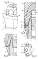
- Fig. 1 device consists of Superstructure of a one-piece bolt, the one Shank with a in the internal thread of the implant screwable external thread and a top with a hexagonal section as well as one upwards tapered end portion for holding a structural member Has.
- the bolt When the device is assembled, the bolt protrudes a conical section in a conical hole section of the ceramic body and pushes the ceramic body against the implant.
- Fig. 2 Device is the one-piece bolt through two separate Parts, namely a sleeve and a screw replaced.
- the Sleeve has a conical section when assembled Device in a conical hole portion of the ceramic body protrudes. Press in assembled device the head of the screw the metallic sleeve against the Ceramic ring, which is pressed against the implant.
- the conical section of the metallic sleeve has two Cams, which are in recesses of the conical hole section of the Intervene ceramic body.
- the conical section of the The latter also has two cams, which are in recesses of the engage the conical hole section of the implant. at both shown in the drawings of FR 2 745 998 A.
- Devices consists of the uppermost, tapering upwards Part of the superstructure - i. the upper end portion of Bolzens or the separate sleeve - made of metal and therefore can can not be ground in the patient's mouth without Get metal chips into the patient's mouth. When a Porcelain crown on the upwardly tapering part of the Supraconstruction is applied, this can be metallic Part also shimmer through the crown and aesthetically be disturbing. Because the implant and the ceramic body as well the latter and the upper part of the bolt (FIG. 1) or the metallic sleeve (Fig.
- the forms for holding a building element certain part of the superstructure down to its lower End a pretty small angle with the axis of the Implant and the superstructure. If a crown on the lower end reasonably smooth on the next to her Section of the device, the crown must leak into a very thin edge there, which is easy breaks out.
- the invention is based on the object disadvantages of to avoid known devices and in particular a Device to create after insertion into a mouth a patient a quick and easy impression or Impression allows and their protruding from the bone Parts as far as desired within the mouth of the Patients can be ground.
- the device should further preferably allow no microorganisms between the body of the implant and the at this attached, ceramic body can penetrate and that the implantable ceramic body in the implant fastened state very stable with the metallic Body is connected so that this ceramic body also under the influence of large, approximately across the Axis of the body acting forces as possible Performs movements relative to the base body.
- the device in the formation of a denture in the mouth a patient from as few separate parts as possible be composable.
- the device allows a rigid, stable and permanent connection of the with a bolt or a Screw fastened, ceramic body with the metallic body. Furthermore, a dentist needs for the Forming a denture in the mouth of a patient only a little assemble separate parts.
- the inventive design of the device allows after inserting the device in a mouth a patient's quick and easy impression taking, i. Impression of the bone protruding and the Soft tissue penetrating parts of the device. If that Hole of the implantable on the implant, ceramic body as Sacklch trained and this ceramic body with a in whose blind hole attaches protruding bolts on the implant In particular, it is not necessary for taking the impression any hole of ceramic, attached to the bolt Body and / or the bolt itself temporarily cover. Furthermore, if necessary, the central, the from the Main body protruding bolt end covering section of the attached to the bolt, ceramic body in the mouth area of the Patients are ground.
- the device has the metallic base body an axial, in cross section enclosed by ceramic material section.
- This Ceramic material consists for example of a originally separate, ceramic body.
- the said ceramic material forming, possibly at the base body attached ceramic body and the one with a bolt on Implant attachable, ceramic bodies are for example by a binder directly to the main body or the Bolt connected.
- the binder may depend on the Training the parts to be joined together from a low-viscosity, can be applied in a thin layer adhesive or from a relatively viscous adhesive or cement exist, to fill at least a relatively large Space is suitable.
- the glue and / or cement can when connecting the parts, for example, at normal Cure room temperature or heated to cure.
- the or each ceramic body may possibly take place through a cement through a braze joint with the metallic body or bolt be connected.
- the binder then exists from a brazing filler, which when connecting the ceramic body with the metallic body or bolt temporarily heated and melted.
- the binder should in all Cases biocompatible, non-toxic and good with the bone and soft tissue of patients.
- the Ceramic body can also be used together with the main body or the bolt form a press-fit and instead of a Binder or in addition to such by a Press connection connected to the main body or bolt be.
- the or each ceramic body may be separately - i. from Main body and any bolts separated - for example from a particle-containing, plastically deformable, more or less easily flowable mass with the help of a mold or the like are formed so as to be at least in Is substantially rotationally symmetric to an axis.
- any bolts separated - for example from a particle-containing, plastically deformable, more or less easily flowable mass with the help of a mold or the like are formed so as to be at least in Is substantially rotationally symmetric to an axis.
- the Shaped body then becomes, before it with the metallic one Basic body or with the possibly existing bolt is heated in the usual way heated and sintered. If two ceramic bodies are present, one or more each of these when used to form a Dentures if necessary still in the mouth of a patient Partially ground by a dentist and thereby the production of a structural element or a Supraconstruction can be shaped individually.
- the preferably attached directly to the body, ceramic material or at least a part of this can Furthermore, an inseparably connected to the body, form ceramic coating.
- the ceramic coating can indissoluble on a region of the metallic body applied, for example, be sprayed.
- This Coating may consist of a thin layer whose thickness for example, only at most 100 microns and, for example, approximately 50 microns.
- the metallic base body and possibly in the hole of the main body fastened, metallic bolts can for example, titanium or a titanium alloy.
- the or each ceramic body and / or the ceramic Coating is preferably made of oxide ceramics, for example from alumina and / or magnesia and / or Zirconia, and is preferably electrically insulating.
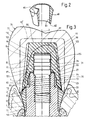
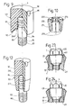
- the apparent in Fig. 1 implant 1 is in general rotationally symmetric to an axis 3 and has a bottom for anchoring in a bone of a lower or upper jaw certain anchoring section 5 and one to the protruding from the bone certain head 7.
- the each other facing away, free ends of the anchoring part and the Kopfs form the first end 8 and the second end 9 of the Implant 1.
- the anchoring section 5 has from the bottom to above a generally cylindrical portion 11 and a trumpet-shaped one widening away from it Section 13, whose outer surface is continuous and smooth to the Outer surface of the generally cylindrical portion 11th adjoined.
- the generally cylindrical portion 11 is with an external thread 15 with a helical Rib 16 provided.
- the external thread 15 is for example designed self-tapping.
- the anchoring section is in near its lower end with several, for example three distributed around the axis 3, elongated grooves and / or holes 17 provided, which the cross helical rib 16 of the external thread.
- trumpet-shaped section 13 At the top, further end of the trumpet-shaped section 13 is a shoulder 21 with one away from the first end 8 above against inwardly inclined conical shoulder surface 22 available. This forms with the axis 3 at an angle of 40 ° up to 50 ° and for example 45 °. To the upper, narrower end of the conical shoulder surface 22 closes a flat, to the axis 3 right-angled annular surface 23 at.
- the head 7 projects upwards away from the annular surface 23 generally rotationally symmetric to the axis 3 and has a essentially parallel to the axis 3, in general cylindrical head portion 25 and a from this way up to the free end of the head and thus to the second Rejuvenating at the end of the entire implant, generally conical head section 27.
- the two head sections 25, 27 each have a rotationally symmetric to the axis, namely cylindrical or conical envelope surface.
- the maximum Diameter of the head is smaller than the diameter of the Outside edge as well as the inner edge of the conical Shoulder surface 22.
- the conical envelope of the in general conical head portion 27 forms with the axis 3 a Angle that is smaller than that of the conical Shoulder surface 22 formed with the axis angle and preferably 15 ° to 25 °, namely and approximately, for example 20 °.
- the axis parallel to the head portion 25 is by a concave curved in axial section annular groove 29 from delimited top end of the shoulder 21.
- the head has one Peripheral surface 30 and at its free end a second End of 9 of the implant forming flat, annular end face 31.
- the peripheral surface 30 of the head 7 is about the axis alternately successive projections and spaces on.
- the spaces consist of axial grooves 33 in the Cross section, for example, arcuate, but instead be V-shaped, trapezoidal or rectangular could.
- axial grooves 33 in the Cross section for example, arcuate, but instead be V-shaped, trapezoidal or rectangular could.
- the in cross section deepest areas of the grooves 33 extend over the whole Length of the axis 3 parallel to the head portion 25 and at least approximately and for example exactly until thinner end of the conical head portion 27 and so too to the second end 9 of the whole implant.
- the implant 1 is coaxial with the axis 3 Blind hole 35 provided. This has one at the second End 9 located, from the annular end face 31st enclosed mouth 36 and from this down to the Row after short, smooth, first cylindrical Hole section 37, an example metric internal thread 38, a transition section 39, a second cylindrical, smooth, i. Threadless hole section 40 and a reason 41.
- the lower end, farther from the mouth, of the Internal thread 38 is located within the itself expanding, trumpet-shaped portion 13 of the implant.
- the diameter of the second cylindrical hole section 40 is smaller than that of the first cylindrical one Hole section 37 and approximately equal to the core diameter of Internal thread.
- the transition section 39 consists of a fairly flat ring groove and has an area in the Axial section is steadily bent and steadily in the cylindrical surface of the second cylindrical hole section passes.
- the reason 41 tapers to its deepest Point down and is by a curved in axial section surface limited, continuous and smooth with the area of the second cylindrical hole portion 40 is related.
- the implant 1 consists of two originally separate, one-piece bodies, namely an elongated, metallic Base 50 and an annular and / or sleeve-shaped, still separately drawn in Fig. 2, ceramic body 60.
- the metallic body 50 forms most of the implant 1 and extends from first end 8 to the second end 9 of the implant.
- the ceramic body 60 forms the area located in the vicinity of the shoulder 21 the outer and / or peripheral surface of the implant, namely the upper portion of the peripheral surface of the trumpet-shaped Section 13, the conical shoulder surface 22 and the outer edge region of the flat annular surface 23.
- Der Metallic body 50 has at the height of the shoulder 21st a the axis 3 and the blind hole 35 enclosing annular throat 51. This is through one at the bottom the throat arranged stop surface 52 and a neck surface 53 formed or limited.
- the stop surface 52 is located approximately at the height of the transition section 39 of the Blind hole 35.
- the neck surface 53 protrudes from the stop surface 52 way up, limiting a neck of the main body and extends to the flat annular surface 23rd
- the ceramic body 60 has a lower end annular bearing surface 62 and a from this to the upper end of the ceramic body extending inner surface 63.
- the stop surface 52 of the main body 50 and the Support surface 62 of the ceramic body 60 form with the Axis 3 an at least approximately right angle, namely an exactly right angle.
- the two surfaces 52, 62 are accordingly.
- the neck surface 53 of the main body 50 and the inner surface 63 of the body 60 are at least approximately parallel to the axis, namely exactly parallel to this as well as cylindrical.
- the inner surface 63 of the ceramic Body 60 encloses the neck surface 53 of the metallic one Main body 50, for example, with small radial clearance.
- the ceramic body 60 is a binder undetachably connected to the main body 50.
- the binder consists of a thin liquid, in a thin layer Applicable adhesive, is between the two cylindrical surfaces 53, 63 arranged and connects them together.
- the two flat surfaces 52 and 62 are located for example, without interposed binder but without a gap, but may also be be connected by a binder.
- the Metallic body 50 and the ceramic body 60th form together after curing of the binder together one rigid, inseparable unity.
- the of metallic base body 50 and formed by the ceramic body 60 Peripheral surface areas of the trumpet-shaped section 13 can in the manufacture of the two bodies 50, 60 such be formed after gluing the two Body without finishing the latter practically smooth, infinitely and seamlessly connect to each other.
- Fig. 3 shows a bone 71, for example the Mandible covering this covering soft tissue 73 - i. the Gingiva - a patient and a device 75.
- the Device 75 has a trained according to FIG. 1, in the Bone 71 inserted implant, 1 a metallic one Bolt 80 and a structural member 77 and a Superstructure with a one-piece, ceramic body 90 and a crown 110 on.
- the bolt 80 and the body 90 are also visible in Fig. 4.
- the metallic bolt 80 has a threaded portion 82 with an external thread 83 and a cylindrical, threadless section 84 whose outside diameter is the same the outer diameter of the threaded portion 82 or a little greater than the latter diameter.
- a cylindrical, threadless section 84 whose outside diameter is the same the outer diameter of the threaded portion 82 or a little greater than the latter diameter.
- the cylindrical portion 84 is at least one annular groove 85th and provided for example with two or even more such.
- Between the threaded portion 82 and the cylindrical Section 84 is a concave curved in axial section annular groove available.
- the ceramic body 90 is cap-shaped and / or sleeve-shaped and has a at the bottom of the body 90th open, at the top by a ceramic material existing cover portion of the body 90 closed, axial hole 91. Its mouth section is through a tapering away from the lower end of the body 90, conical bearing surface 92 formed. This forms composite device 75 with the axis 3 the same Angle as the shoulder surface 22 and is at least on the inner area of this gap-free up. On the conical Support surface 92 follow up a cylindrical Inner surface 93 and a conical inner surface 94.
- This Inner surfaces 93, 94 enclose the generally cylindrical head portion 25 and conical head portion 27, in particular between the conical head portion and the conical inner surface 94 at most a very small Game is available.
- To the conical inner surface 94 closes an annular, radial to the axis 3 and right-angled inner surface 95, which is the end face 31 of the Implant 1 faces a smaller distance.
- To the inner end of the radial inner surface 95 closes a cylindrical inner surface 96, which is the cylindrical Section 84 of the bolt 80 with at most small game encloses.
- the upper end of the hole 91 is defined by a to most flat end surface 97 formed, the end surface facing the bolt in the distance.
- the cap-shaped, Ceramic body 90 has a generally to the axis 3rd rotationally symmetric, namely an upward tapered, conical peripheral surface 98, but with some recesses 99 distributed along the circumference provided, in which a turning tool can engage.
- the body 90 has at the upper end an end face which, in essence, i.e. apart from the recesses 99, rotationally symmetric, and also smooth, even and hole-free.
- the outer edge of the conical bearing surface 92 of the For example, ceramic body 90 has a smaller one Diameter than the outer edge of the shoulder surface 22, so that the latter still one the lower edge of the ceramic Body has 90 enclosing area.
- the crown 110 exists For example, from a gold alloy and / or porcelain and sits in the finished device firmly on the cap-shaped, ceramic body 90.
- the crown lies on the outer region of the shoulder surface 22 and closes infinitely and smoothly to the upper end of the peripheral surface of the trumpet-shaped section 13 of the implant.
- ceramic body 90 is in the uppermost cylindrical portion of the hole 91 by a binder 120, for example, a relatively viscous, thick layer Applicable cement, unsolvable with the cylindrical section 84 of the bolt 80 connected.
- the cement then fills the Ring grooves 85, and the space between the upper end of the bolt 80 and the end surface 97 of the hole 91 from. Depending on radial play may also be between the annular cylindrical peripheral surface portions of cylindrical portion 84 of the bolt and the cylindrical Inner surface 96 of the body 90 cement may be present. It was nor noted that the binder in Fig. 4 is not was presented.
- the bolt 80 and the cap-shaped, ceramic bodies 90 form after curing of the Binder 120 or cement together a rigid, inseparable unit 122.
- the metallic base 50, the metallic bolt 80 and the two ceramic bodies 60 and 90 are in manufactured a manufacturer.
- the two ceramic Body 60 and 90 are in the factory by means of the already mentioned binder, insoluble and rigid with the Base 50 or bolt 80 connected. That from the Main body 50 and the ceramic body 60 existing Implant 1 and the bolt 80 and ceramic body 90 existing unit 122 will then be considered two units For example, to a dental practice or dental clinic delivered.
- a dentist can implant 1 according to FIG. 3 to use transgigival in the mouth of a patient, so that the anchoring part 5 of the implant 1 to a large Part is anchored in a hole of the bone 71 and the upper end portion of the implant 1 from the bone protrudes.
- the attached to the base 50, ceramic Body 60 extends approximately from the crest of the bone 71 almost to the crest of the soft tissue.
- the dentist can then first with a screw a cap-shaped Attach the healing element to implant 1 until the Operation wound healed. After the healing phase, the Dentist remove the healing element and remove it from the bolt 80 and the ceramic body 90 existing unit 122 am Attach implant 1.
- the dentist can do this with a Rotary tool in the recesses 99 of the ceramic body 90th engage and the threaded portion 82 of the bolt 80 in the Screw internal thread 38 of implant 1 until the Auflege requirements 92 of the ceramic body 90 without gaps on the Shoulder surface 22 of the implant rests.
- the lower End portion of the cylindrical portion 84 of the bolt 80th sticks out at the finished device with at most small, radial play a little in the cylindrical hole section 37 of the implant 1 into it.
- the out of the bolt 80 and the ceramic body 90 existing unit 122 is then through the bolt releasably but stably connected to the implant 1.
- This Binder 125 consists for example of a Temporary cement, as is the case from dentists to temporary Attachment of provisional mounted components used and that gives a fairly firm connection, but allows the interconnected parts with a to separate power again from each other.
- the binder 125 can also come from a normal, for a permanent, Insoluble compound provided cement.
- the any existing binder 125 is in addition to still releasably screwed into the implant bolt 80 still one only with a certain force or not at all non-destructive detachable connection of the ceramic body 90 with the implant 1.
- the implant 1 and the bolt 80 and the ceramic body 90 existing unit 122 form according to their detachable or insoluble compound together a stable, rigid support.
- the dentist has to So for the creation of this support only two separate, the dentist provided units, namely the Implant 1 and unit 122, in the patient's mouth put together. This simplifies the construction of a Dentures in the mouth of a patient.
- the dentist can for the formation of a Denture an impression of the upper implant part and the Take body 90, make the crown 110 and make the Crown with unmarked cement on the ceramic body 90 and possibly attach to the shoulder surface 11.
- the dentist can the ceramic body 60th and / or the ceramic body 90 for optimizing the mold dentures still inside the patient's mouth grind in places.
- Figures 2, 3 and 4 by dot-dashed lenses indicated areas 65 and 105 of the two originally rotationally symmetrical body 60 or 90 weggeschliffen become. Since the shoulder surface 22 facing away from the end portion of the ceramic body 90, the upper, from the implant. 1 outstanding end of the bolt 80 covers, if necessary also a part of the top of the bolt covering, be ground away ceramic material.
- the bolt 80 is in both the internal thread 38 and in the cylindrical hole portion 37 of the implant 1 side supported.
- the cap-shaped ceramic body 90 is replaced by the held cylindrical portion 84 of the bolt and laterally supported. Furthermore, the body 90 is free of play and gap-free on the shoulder surface 22 of the implant and is also supported laterally from the head 7, and indeed in particular by the conical head section 27 to the upper, second end 9 of the implant 1.
- the structural element 77 Therefore, in addition to approximately axial forces, large, approximately transverse to the axis 3 directed forces on the implant transferred, without due to these forces movements of the implant. This ensures a big one Stability of the formed dentures.
- the adjacent to the dentures soft tissue 73 is after healing with the finished device at least for the most part on the peripheral surface of the annular Ceramic body 60 and is practically grown on this. Maybe there is still soft tissue on the example porcelain crown 110. On the other hand that is Soft tissue nowhere, or at least almost anywhere metallic surface of the implant. This works Inflammation of the soft tissue. If the crown 110 made of porcelain, the ceramic body 90, the formation of a shiny, color a beautiful, natural tooth corresponding crown. If the crown 110 off a metallic material, it is through the both ceramic bodies 60 and 90 against the metallic Main body 50 of the implant electrically isolated, so that no galvanically generated electric current from the crown 110 can flow to the implant 1.
- ceramic body 90 can by the knit-dotted indicated ceramic body 90 'replaced become.
- This is essentially approximately cylindrical and has at its lower end an annular bearing surface, whose outer diameter is approximately equal to or equal to Outside diameter of the shoulder surface 22 is.
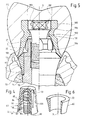
- the implant 1 of the device shown in Fig. 5 is the same as that in Figures 1 and 3 apparent implant.
- the apparent in Fig. 5 Device has, however, instead of the bolt 80 a Occlusal screw 180 and instead of the ceramic body 90th a metallic body 190.
- the screw 180 has a Threaded portion 182 and a head 183 with a Polygonal hole, for example a hexagonal hole.
- the Metallic body 190 is cap-shaped and / or sleeve-shaped and has, however, instead of an axial blind hole through axial hole 191. This is stepped and has At the bottom is a conical support surface 192 which extends to the Outside edge of the conical shoulder surface 22 of the implant the shoulder surface rests.
- the body 190 also has a conical inner surface 194, which the conical head portion 27 of the implant 1 with at most small game encloses.
- the hole 191 also has an upwardly conical expanding support surface 196, on which the head of Occlusal screw with a conical surface rests.
- the Construction element of the apparent in Fig. 5 device has again a crown 110. This is to the body 190 molded and consists, for example, as the construction element As shown in FIG. 3 in general made of porcelain or a Gold alloy.
- the metallic body 190 has one of Outside edge of the support surface 192 away upward Outside surface section, smooth and steady to the Outside surface of the ceramic body 60 connects and on then the outer surface of the crown smooth and steady adjoined.
- the crown 110 has above the head 183 of the Occlusal screw 180 indicated by dash-dotted lines, cylindrical area 132. This consists for example of one after inserting the screw 180 with an insert and / or cement or the like sealed hole and can if necessary later without damaging the rest of the crown again exposed - for example, drilled - be. This allows the occlusal screw to be released later and the crown 110 and the body 190 from the implant 1 to separate.
- the adjacent to the soft tissue surface of Device is again at least in large part formed by the ceramic body 60.
- the ceramic body 60 of the in Figures 1, 3 and 5 shown implant 1 can by the in Fig. 6 apparent, ceramic body 60 are replaced. This differs from the previously described body 60 in that at the upper end a plane, to the axis 3 has right-angled ring surface. This is located at finished implant below the in Fig. 1 from the main body 50th formed main part of the annular surface 23 or in the same Height like the latter and forms on its own or together with the annular surface formed by the base body 50 a shoulder surface 22 perpendicular to the axis 3.
- the sleeve and / or annular body 60 could also instead of the upwardly outwardly inclined peripheral surface one at least partly cylindrical or even against the top have an inwardly inclined surface.
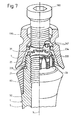
- the device shown in part in Fig. 7 has an implant 1, its anchoring part 5 and shoulder 21 the same as in the implant according to FIG. 1 are formed.
- the head 7 is formed differently than in the Fig. 1 illustrated implant.
- the generally to the axis 3 parallel and generally cylindrical head portion 25th is still provided with an external thread 226.
- the axial grooves 33 in cross section instead of arcuate for example, approximately rectangular or trapezoidal.
- the annular end face 31 along with the Distribute circumference, radial recesses or grooves 233, 234 provided, wherein a plurality of identical, first recesses or Grooves 233 and a second, wider and / or deeper Recess or groove 234 are present.
- FIG. 7 are still an occlusal screw 180 and a metallic, cap and / or sleeve-shaped body 190 can be seen.
- the latter is similar to the body 190 shown in FIG formed, but still has radially inward Projections 247th These can with at most small game in engage one of the first recesses or grooves 233 and the body 190 thereby rotatably with respect to the implant 1 in one of several rotational positions selectable rotational position position.
- the implant shown in FIG. 7 can instead of the occlusal screw 180 and the metallic Body 190 a metallic bolt with a rigid at this attached, closed up, ceramic body attached become.
- This bolt and ceramic body can be similar like the corresponding parts in FIGS. 3 and 4 be educated.
- the ceramic body has in particular no protrusions corresponding to the projections 247, so that consisting of the bolt and the ceramic body Unit screwed to the implant by turning it can be.
- the recesses or grooves 233 then have no positioning effect.
- the implant shown in FIG. 7 thus allows different types of attachment.
- Fig. 8 device has an implant 1, according to the left or right Figure half can be formed. Both half in the Fig. 8 illustrated implant variants have from the bottom End of the anchoring part 5 to the shoulder 21 approximately the same outer shape as that shown in Fig. 1 Implant.
- Each implant shown in Fig. 8 has in particular a generally cylindrical section 11, a trumpet-shaped section 13 and a shoulder 21 with a conical shoulder surface 22.
- the implant has a metallic body 50 on, which in the left Figurine half drawn variant also at least the most of the trumpet-shaped section 13 and the conical shoulder surface 22 forms.
- the from the outside edge the shoulder surface 22 to near the lower end of the trumpet-shaped portion 13 extending portion of Peripheral surface of the metallic base body 50 is in the left-hand variant with a sprayed on, ceramic coating 260 provided, for example, approximately 50 ⁇ m thick.
- the in the right half of Fig. 8 drawn variant of the implant has - similar to the Implant according to Figures 1 and 3 - an annular and / or sleeve-shaped, ceramic body 60, the at least the outermost part as well as the outer edge of the conical shoulder surface 22 and for example the largest Part of this or even the whole conical shoulder surface 22 forms.
- the implant shown in Fig. 8 has no the head 7 of the implant shown in Fig. 1 appropriate head.
- the axial blind hole 35 has a from Inner edge of the conical shoulder surface 22 formed mouth 36. Furthermore, the blind hole 35 between its internal thread 38 and its mouth 36 one to the latter flared, conical hole section 267.
- the apparent in Fig. 8 device further has a metallic bolt 80 and a sleeve and / or cap-shaped, ceramic body 90.
- the bolt 80 and the Body 90 can also be seen in FIG. 9.
- the bolt 80 has a threaded portion 82 and a cylindrical portion 84. The latter is near its threaded portion opposite end provided with annular grooves 85, while his the area subsequent to the thread section is slotless and has a smooth cylindrical surface.
- the illustrated in Fig. 8 ceramic body 90 in turn has an axial, open at the bottom, closed top, for the most part cylindrical hole 91 and a conical bearing surface 92, the composite at Device on the shoulder surface 22 occurs.
- the peripheral surface of the body 90 has a bottom annular, narrow upwardly widening section, at least approximately steadily to that of coating 260 formed peripheral surface portion of the implant adjoined.
- the upper, most of the peripheral surface of Body 90 is cylindrical. At the upper end of the body 90 Some recesses are 99 for attacking with one Turning tool available.
- the upper end portion of the bolt 80 protrudes as in the embodiment shown in Fig.
- FIG. 8 has another also shown separately in Fig. 10, metallic Ring 270.
- This one is at compound Device in the conical hole section 267 of the implant, encloses the cylindrical portion 84 of the bolt 80 and has a conical outer surface 271 and a cylindrical Inner surface 272.
- the conical inner surface of the hole section 267 and the conical outer surface 271 form with the axis 3 the same angle, preferably 5 ° to 10 ° and the Example is about 8 °.
- the ring is through in Fig. 10 apparent, alternately from below and above incisions cut 273 into slightly resilient segments divided.
- a deformable pressure ring 275 is arranged between the annular surface 269 of the ceramic Body 90 and the flat, upper end surface of the ring 270 .
- the bolt 80 is in turn already in the factory by the drawn in Fig. 8, but not in Fig. 9 binder 120 undetachably connected to the ceramic body 90, so that the bolt 80 and the body 90 together a solid unit 122 form.
- the pressure ring 275 and the ring 270 can also already in the factory on the bolt 80th be pushed, in which case the ring 270 slightly on the bolt clamped, but still slidable along this.
- the Implant 1 and the unit 122 with the on the bolt 80th plugged rings 271 and 275 are for example at delivered to a dentist. This can then the implant 1 Insert transgingival into the mouth of a patient. After this Healing the implant 1, the dentist, the unit 122 with the two rings 271, 275 connect to the implant 1, i.e.
- the deformable pressure ring 275 presses the ring 270th down, leaving this with its outer surface 271 stuck and practically free of play on the inner surface of the conical Extension 267 and with its inner surface 272 at the cylindrical surface of the bolt 80 rests.
- the ring 271 centered therefore the bolt and supports this between the Internal thread 38 and the mouth 36 of the blind hole 35 to almost to the mouth 36 laterally in the implant.
- the implant 1 and the unit 122 together form a stable one Support.
- the dentist may, after inserting the unit 122 in the patient's mouth if necessary at least one Grind away area 105 of the ceramic body 90 and a Crown or other superstructure build on this.
- the adjacent to the soft tissue surface of the denture is then at least to a large extent by the Peripheral surface of the ceramic transition 260 and possibly even through a section of the peripheral surface of the ceramic body 90 is formed.
- the device shown in part in FIG. 11 has one according to the left or right half of the figure trained implant 1.
- the two half each drawn implant variants are the same as those in Fig. 8 drawn implant variants designed and have a metallic base body 50 and a ceramic Cover 260 or body 60.
- the device according to FIG. 11 also has a unit shown separately in FIG 122 with a metallic bolt 80 and a ceramic Body 90.
- the bolt has a threaded portion 82 as well a cylindrical portion 84 and is the in Fig.
- ceramic body 90 has a conical section 291 extending to the lower end of the Body 90 tapers and with device assembled fixed and free of play in the conical hole section 267 of Implant sits.
- the body 90 also has an im general cylindrical section 292 at assembled device above the implant 1 located.
- the body 90 of the illustrated in Fig. 11 Device is in contrast to the body 90 according to FIG. 8 not on the shoulder surface 22, but from this enclosed.
- the bolt 80 in turn projects into an axial, top closed hole 91 of the body 90 in and is through a Binder 120 connected to this.
- a dentist can use the unit 122 screw into the implant.
- the conical section 291 is then free of play and firmly on the inner surface of the conical hole portion 267 and is radially through this as well as axially supported.
- the contiguous Cone surfaces also provide an inhibition and clamping action, so that the unit 122 is practically unintentional can solve by itself.
- the conical could Section 291 of the body 90 additionally with a binder be fastened in the hole section 267.
- the cylindrical one Section 292 of the ceramic body 90 may, if necessary be ground so that it, for example, the in Fig. 11 dash-dotted form receives and the area 105th is ground away.
- At the conical section 292 can for Example not shown, on the shoulder surface 22 resting crown are attached.
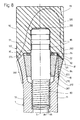
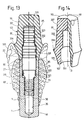
- the device partially shown in FIG. 13 has an implant 1.
- This consists exclusively of one one-piece metal body 50. This is up to but its upper, second end cylindrical possibly a not drawn external thread exhibit.
- the implant has an annular, upper-end, plane, to the axis 3 rectangular shoulder surface 22 and does not have a head rising above the shoulder surface.
- the axial blind hole 35 of the implant has a from the inner edge the shoulder surface 22 formed mouth, then to this a cylindrical hole section 37 and below an internal thread 38.
- the diameter of the cylindrical Section 37 is significantly larger than the maximum Diameter or nominal diameter of the internal thread 38.
- a hole portion 311 is provided along the Circumference distributed, inward protrusions and between has these existing spaces, the latter form axial grooves.
- the device according to FIG. 13 in turn has a Unit 122 with a metallic bolt 80 and a with this connected by a binder 120, ceramic Body 90.
- the bolt 80 has a variant in this variant Thread portion 82 and away from this in turn one first cylindrical bolt portion 321, a second cylindrical bolt portion 322 and a third cylindrical bolt portion 323.
- the second cylindrical Bolt portion 322 has a larger diameter than the two other cylindrical sections 321, 323.
- the upper Area of the second cylindrical portion 322 and the third cylindrical portion 323 are provided with annular grooves 85th Mistake.
- ceramic body 90 has an axial, in turn hole 91 completed above. This one has its on Mouth subsequent, further, cylindrical Hole section 331 and a narrower, cylindrical Hole section 332.
- the annular grooves having area of cylindrical portion 322 and the cylindrical portion 323 of the bolt sit with at most small, radial play in the hole portion 331 and 332 of the ceramic body 90 and are connected to the body 90 by the binder 120.
- the ceramic body 90 is assembled Device with its plane, perpendicular to the axis 3 Support surface 92 on the shoulder surface 22 of the implant on, wherein the two surfaces 22, 92 are the same Outer diameter and same inner diameter have.
- the on the support surface 92 subsequent section 331 of the body 90 has a slightly curved concave in axial section, after above trumpet-shaped widening peripheral surface, at composite device at least approach steadily the cylindrical peripheral surface of the implant 1 connects.
- the upper end of the trumpet-shaped portion 335 is over a concave curved in axial section and / or conical Shoulder surface 336 with an upwardly tapering, connected conical section 337. The latter is with a few recesses 99 provided.
- the implant 1 becomes subgingival in its use a bone 71 is inserted, so that the shoulder surface 22 approximately at the level of the bony crest below the Soft tissue is 73, but after cutting the Soft tissue accessible from the environment of the bone is.
- the bolt 80 is the Unit 122 screwed into the implant.
- the lower part of the second cylindrical bolt portion 322 then becomes radially approximately free of play in the cylindrical hole section 37 guided and supported during implantation of the implant Bolt portion 321, the portion 311 of the hole with a large Game and, for example, penetrates without contact.
- the Ceramic body 90 may, in turn, be strained become.
- Crown on the conical portion 337 of the body 90th be attached to the crown on the shoulder surface 336 rests.
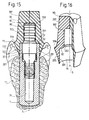
- the implant 1 of the device shown in FIG is the same as the implant according to FIG Bolt 80 of the unit 122 shown in FIG. 15 has the same as shown in Fig. 13 bolt a threaded portion 82 and three cylindrical bolt sections 321, 322, 323, however, the second cylindrical bolt portion 322 is shorter, has no grooves and a short conical bolt portion 351 with the cylindrical portion 323 is connected.
- the ceramic body 90 of FIG. 15 The apparent unit 122 is still separate in FIG. 16 and has an axial hole 91 with two cylindrical hole sections 331, 332.
- FIG. 15 Between the at the Mouth of the hole 91 subsequent, another hole section 331 and the narrower hole portion 332 are an annular, level, perpendicular to the axis 3 bearing surface 92 and a upwardly tapering, conical hole section 353 available.
- the apparent in the figures 15, 16 body 90th has similar to the drawn in Figures 13, 14 body an upwardly trumpet-shaped expanding section 335, a shoulder 336 and a conical section 337.
- the outer edge of the shoulder surface 336 is located approximately in height bearing surface 92.
- the cylindrical Bolt portion 323 and the conical bolt portion 351 of the Bolts sit in the cylindrical hole section 332 and in conical hole portion 353 of the body 90, wherein the bolt again by a binder 120 to the body 90th connected is.
- the implant 1 shown in FIG. 15 is transgingival used, so that the shoulder surface 22 of the implant above the bone 71 approximately at the level of the crest of the Soft tissue 73 is located.
- the bolt 80 in the blind hole 35 of the implant is screwed, is the second cylindrical bolt portion 322 completely in the cylindrical Hole section 37 of the implant and is approximately flush with the mouth of the hole 35.
- the ceramic body 90 is then with its bearing surface 92 on the implant shoulder surface 22 on.
- the upper end portion of the implant 1 sits with at most small, radial play in the cylindrical Hole section 331 of the body 90 and may possibly by a thin layer coatable adhesive to the body 90 connected.
- the slightly curved concave in axial section Peripheral surface of the portion 335 of the ceramic body 90th goes at the bottom of this almost stepless in the cylindrical peripheral surface of the implant over.
- the at the Soft tissue 73 adjacent surface of the device is at least for the most part by the peripheral surface of the Section 335 of the ceramic body 90 is formed.
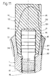
- the device shown in Fig. 17 has an implant. 1 with a metallic base body consisting of two integral, releasably interconnected parts, namely a generally cylindrical body 360 and an in consists of this screwed intermediate bolt 370. At this is an annular and / or sleeve-shaped, ceramic Body 60 held.
- the intermediate bolt 370 is a screwed in another bolt, like the example in Figures 3 and 4 apparent bolts designated 80 is.
- a ceramic body is attached, the cap-shaped and closed at the top and like that Cap-shaped, ceramic body according to FIGS. 3 and 4 designated 90.
- the generally cylindrical body 360 is similar to the one-piece body 50 as shown in FIG. 13.
- the blind hole of the body 360 has between the internal thread 38 and the projections as well Interstices having hole portion 311 still one threadless, cylindrical hole portion 361, whose Diameter equal to the nominal diameter of the internal thread or a little bigger than this and smaller than the diameter of the at the mouth of the blind hole 35 subsequent, cylindrical hole portion 37 is.
- the intermediate bolt 370 has a screwed into the internal thread 38 Thread section 371, two cylindrical, in the Hole sections 361 and 37 guided bolt sections 372 or 373, a bunch 374 and one up from the latter protruding, cylindrical bolt portion 375.
- the collar 374 has above and below a flat ring surface and lies on the annular end surface of the body 360.
- the intermediate bolt 370 has one ending in its upper end Blind hole 377 provided, which has an internal thread 378.
- the bolt 80 is with its threaded portion in the internal thread 378 of the intermediate bolt 370 screwed.
- the sleeve-shaped, ceramic Body 60 has a flat annular surface at its upper end, for example, a little above the annular End face of the bolt 370 is located and as a shoulder surface of the Implant 1 can be considered.
- the cap-shaped, permanently attached to the bolt 80 and together with this one Unit 122 forming, ceramic body 90 is located with a level, annular bearing surface on said Ring surface of the ceramic body 60 and presses it against the collar 374.
- the sleeve-shaped, ceramic body 60 may possibly only on the intermediate bolt in this variant 370 plugged in and then at assembled device by the unit 122 am Between bolts 370 held.
- the ceramic body 60 However, for example, by a press connection and / or a binder permanently attached to the intermediate bolt 370 be.
- the metallic body 360 of the implant 1 is used subgingivally, so that the soft tissue attached to the ceramic body 60 and possibly even a little the ceramic body 90 and the collar 324 adjacent.
- the apparent in Fig. 18 device has a in general cylindrical implant 1 with a one-piece, Metallic body 50 and attached to this, ring and / or sleeve-shaped, ceramic body 60th Das Blind hole 35 has between its mouth and his Internal thread 38 analogous as in the drawn in Fig. 1 Basic body a short, cylindrical hole section 37, the at least equal to the nominal diameter or maximum Diameter of the internal thread and, for example, a little greater than the nominal thread diameter.
- the base body 50 and the ceramic body 60 have on their upper end planar annular end surfaces, of which that of the ceramic body 60, for example, a little is located above the end face of the main body and as Shoulder surface of the implant is used.
- the two annular ones However, end surfaces could also be flush with each other.
- the device according to FIG. 18 also has one Secondary part or a building element 390 with a head 391 and a bolt 392.
- the bolt 392 has one in the Internal thread 38 screwed threaded portion approximately is supported radially in the hole section 37 without play.
- the head 391 lies with an annular, flat bearing surface gap-free on the upper end surface of the ceramic body 60th on. This can be plugged and by the construction element 390th held on the body 50 or by a press connection and / or a binder insoluble in the body be attached.
- the head 391 is, for example, conical and has a blind hole opening into its upper end with a Inner thread.
- the implant 1 is transgingival in a mouth used by a patient.
- the device according to FIG. 18 serves together with at least one other, same Device and / or possibly a natural tooth for Holding and / or forming a web construction, wherein a not drawn web can be attached to the head 391.
- the implant 1 shown in FIGS. 19 and 20 is formed similar to the implant 1 and has a one-piece, metallic body 50 and an on this attached, ring and / or sleeve-shaped, ceramic body 60.
- the ceramic body 60 has on its front side at the upper, inner edge of the conical shoulder surface 22nd still a relatively wide, annular for the most part level End face 401.
- the unit 122 depicted in FIG be attached which has a bolt 80 and one at this fixed, ceramic body 90 has.
- the bolt 80 and the ceramic body 90 are similar to FIG. 3 educated.
- the ceramic body 90 is enclosed assembled device, in particular with a annular, conical bearing surface 92 on the conical Shoulder surface 22 on.
- the drawn in Fig. 20 body 90th has a annular throat 405, in the assembled at Device the or each projection 402 with game protrudes.
- the throat 405 allows the unit 122 through Rotate without hindrance by the projection 402 or the Screw projections 402 to the implant.
- the partially in Fig. 21 apparent, preferably metallic, for example gold or a gold alloy existing, cap-shaped body 410 may instead of in Fig. 20 drawn unit 122 on the implant according to the Figures 19, 20 are attached.
- the body 410 is similar as shown in Fig. 5 apparent body 190 has and has like this a continuous axial hole 411, so he analogous to the body 190 with an occlusal screw on Implant can be attached.
- the body 410 has one annular, generally conical bearing surface 412, the at least in part on the conical shoulder surface 22 of the Implant 1 rests when the body 410 at this is attached.
- the support surface 412 is equipped with several for example, twelve - evenly along the support surface distributed recesses 413 provided.
- the body 410 at Implant When the body 410 at Implant is attached as shown in FIG. 19, projects the or each Projection 402 into a recess 413 and secures the Body 410 against spins.
- the body 410 can therefore optionally in one of several rotational positions with respect to Implant 1 are rotationally fixed.
- the device shown in Fig. 22 is similar formed as the device according to FIG. 20.
- the in Fig. 22 apparent, ceramic body 60 but instead a conical shoulder surface a flat, annular Shoulder surface 22, to the inside of an annular step 423rd with a steep, slightly conical or cylindrical flank and a plane, with at least one projection 402 attached ring surface connects.
- the ceramic body 90 is designed such that it has an annular, even bearing surface gap-free on the flat shoulder surface 22 rests.
- the implant 1 shown in FIG. 23 has a similar one Outline shape like the implant according to FIGS. 19 and 20, However, has a main body 50, which consists of two originally separate parts, namely a primary part 431 and a secondary parts 432 is formed. The latter has a screwed into a blind hole of the primary part bolts and a protruding from the primary section, the forms the head 7 of the implant 1.
- the primary part 431 attached, ceramic body 60 forms the shoulder surface 22nd of the implant and has two or more along its circumference distributed protrusions 402 or cams 402.
- the implant shown in Fig. 24 has like the Implant according to FIG. 23 one of a primary part 431 and a secondary part 432 existing, metallic body 50.
- the attached to the primary part 431, ceramic body 60th has on its front side instead of projections 402 at least one recess 433 and, for example, two or more circumferentially distributed recesses 433.
- Each Recess 433 consists of a radial to the axis 3 groove.
- the implant according to FIG. 24 can optionally a unit with a bolt and a ceramic, not in the recesses engaging body or a metallic, cap-shaped body are attached, the at least one in a recess 433 engaging projection and is thereby rotationally fixed.
- the ceramic bodies 60th formed shoulder surfaces 22 in all in the figures 19, 20, 22 to 24 illustrated implants along the whole The circumference is completely smooth and either conical or flat. The attached to these implants body can therefore despite the protrusions or recesses along the whole Scope of the shoulder surfaces gapless against these.
- the Projections 402 and recesses 433 of the ceramic body 60th are located on a ring axis coaxial to the axis 3, the head of the implant in axial projection encloses.
- the projections 402 and recesses 433 have Therefore, a relatively large, radial distance from the axis 3. This contributes to accurate positioning and stable Anti-rotation of bodies attached to the implants are fixed and with the projections or recesses in Engage.
- the projections or Recesses can then, for example, in radial Direction only over the inner part of the shoulder surface extend so that the shoulder surface outside along a the entire circumference, smooth, even Section has.
- the ceramic bodies 60 of the implants according to the Figures 19 to 24 and in the preceding paragraph described implant variants can - analogous to the Implant according to FIG. 7 - several identical, first Projections or recesses and a differently sized, second projection or a differently sized, second Have recess.
- the with a screw on the implant fastenable body can then be trained with the Projections and / or recesses of the ceramic body have cooperating recesses and / or protrusions, that an implant is the body attached to it - depending of its training - either in one of several Rotary positions or only in a single rotational position rotatably positioned.
- the devices can still be changed in other ways become. It can in particular features various Embodiments are combined with each other.
- a bolt 80 and the hole 91 attached to the bolt, ceramic body 90 may be non-rotationally symmetric in cross section to the axis Have sections that with at most small game fit into each other.
- sections may be polygonal or have at least one flat surface parallel to the axis is or with this an angle different from 90 ° forms.
- the ceramic body 90 becomes non-rotatable positioned on the bolt and additionally against rotations secured relative to the bolt.
- the anchoring portion of the implant may also be at least approximately over its entire height to the lower,
- the first end of the implant is similar to a natural one Tooth root rejuvenate, but for example another Having external thread, so that the implant after the Extraction of a tooth immediately inserted into the bone can be.
- implants also in combination with others Construction elements or superstructures and other parts used, for example, to form Single teeth, bridges and dentures with several artificial ones Serve teeth.
Landscapes
- Health & Medical Sciences (AREA)
- Oral & Maxillofacial Surgery (AREA)
- Orthopedic Medicine & Surgery (AREA)
- Dentistry (AREA)
- Epidemiology (AREA)
- Life Sciences & Earth Sciences (AREA)
- Animal Behavior & Ethology (AREA)
- General Health & Medical Sciences (AREA)
- Public Health (AREA)
- Veterinary Medicine (AREA)
- Engineering & Computer Science (AREA)
- Ceramic Engineering (AREA)
- Dental Prosthetics (AREA)
- Prostheses (AREA)
- Dental Tools And Instruments Or Auxiliary Dental Instruments (AREA)
- Mechanical Operated Clutches (AREA)
Abstract
Description
Claims (10)
- Vorrichtung zum Halten und/oder Bilden eines Zahnersatzes, mit einem Implantat (1), das einen metallischen, zum mindestens teilweisen Verankern in einem Knochen (71) bestimmten, ein Loch (35) aufweisenden Grundkörper (50) aufweist, und mit einem keramischen, ein Loch (91) aufweisenden Körper (90), der mit einem metallischen Bolzen (80) oder einer einen Kopf (183) aufweisenden Schraube (180) am Grundkörper (50) befestigbar ist, wobei der Bolzen (80) bzw. die Schraube (180) im Loch (38) des Grundkörpers (50) befestigbar ist, dadurch gekennzeichnet, dass das Loch (91) des keramischen Körpers (90) ein Sackloch ist und ein dem Grundkörper (90) abgewandtes, durch keramisches Material des keramischen Körpers (90) abgeschlossenes Ende hat und der Bolzen (80) in das Loch (91) des keramischen Körpers (90) hineinragt und starr mit diesem verbunden ist oder dass der Kopf (183) der Schraube (180) auf einer Auflagefläche des keramischen Körpers (90) aufliegt.
- Vorrichtung nach Anspruch 1, dadurch gekennzeichnet, dass das mindestens zum Teil vom metallischen Grundkörper (50) gebildete Implantat (1) eine Achse (3) und eine mit dieser einen Winkel bildende, ringförmige Schulterfläche (22) hat und dass der mit einem Bolzen (80) oder mit einer Schraube (180) am Implantat (1) befestigbare, keramische Körper (90) bei zusammengesetzter Vorrichtung mit einer ringförmigen Auflagefläche (92) auf der Schulterfläche (22) des Implantats (1) aufliegt oder einen im Loch (35) des Grundkörpers (50) sitzenden Abschnitt (291) hat.
- Vorrichtung nach Anspruch 2, dadurch gekennzeichnet, dass das Implantat (1) ein erstes zum tiefsten Einsetzen in den Knochen (71) bestimmtes Ende (8) und ein zweites Ende (9) hat und dass die Schulterfläche (22) des Implantats (1) mindestens zum Teil konisch und nach aussen zum ersten Ende (8) des Implantats (1) hin geneigt ist und die Auflagefläche (92) des am Implantat (1) befestigbaren, keramischen Körper (90) konisch ist und auf der mindestens zum Teil konisch ausgebildeten Schulterfläche (22) des Implantats (1) aufliegt oder dass ein Abschnitt (267) des Lochs (35) des Implantats (1) den im Loch (35) sitzenden Abschnitt (291) des am Implantat (1) befestigbaren, keramischen Körpers (90) mindestens radial abstützt oder dass die Schulterfläche (22) mindestens zum Teil eben ist und der am Implantat (1) befestigbare Körper (90) mit einer ebenen, ringförmigen Auflagefläche (92) auf der ebenen Schulterfläche (22) bzw. einem ebenen Teil von dieser aufliegt und durch eine zylindrische oder konische Fläche des Implantats (1) mindestens annähernd radial spielfrei abgestützt ist.
- Vorrichtung nach Anspruch 2 oder 3, dadurch gekennzeichnet, dass das Implantat (1) einen von der Schulterfläche (22) wegragenden Kopf (7) hat, der den am Implantat befestigbaren, keramischen Körper (90), wenn dieser bei zusammengebauter Vorrichtung auf der Schulterfläche (22) aufliegt, bei mindestens einer vom Loch (91) des am Implantat (1) befestigbaren, keramischen Körpers (90) gebildeten Innenfläche (93, 94) mit höchstens kleinem, radialem Spiel abstützt.
- Vorrichtung nach Ansprüche 2 bis 4, dadurch gekennzeichnet, dass das Loch (35) des Implantats (1) einen konischen Abschnitt (267) hat, in dem ein konischer Abschnitt (291) des am Implantat (1) befestigbaren, keramischen Körpers (90) spielfrei sitzt.
- Vorrichtung nach einem der Ansprüche 2, 3 oder 5, dadurch gekennzeichnet, dass die ringförmige Schulterfläche (22) den am Implantat (1) befestigbaren, keramischen Körper (90) bei der Mündung des Lochs (35) des Implantats (1) in einer axialen Projektion umschliesst und eine freie Auflage für einen Teil eines Aufbauelements (77), zum Beispiel für eine Krone (110) oder einen Teil einer Brücke oder einen Teil einer mehrere künstliche Zähne aufweisenden Prothese bildet.
- Vorrichtung nach Anspruch 2 oder 3, dadurch gekennzeichnet, dass der am Implantat (1) befestigbare, keramische Körper (90) eine ringförmige Schulterfläche (336) aufweist.
- Vorrichtung nach einem der Ansprüche 2 bis 7, dadurch gekennzeichnet, dass das Implantat (1) einen den metallischen Grundkörper (50) umschliessenden, ringförmigen, durch eine Press-Verbindung und/oder ein Bindemittel und/oder eine Hartlöt-Verbindung am Grundkörper (50) im Wesentlichen unlösbar befestigten, keramischen Körper (60) oder einen auf den Grundkörper (50) aufgebrachten Überzug (260) aufweist.
- Vorrichtung nach einem der Ansprüche 1 bis 8 dadurch gekennzeichnet, dass der mit einem Bolzen (80) am Implantat (1) befestigbare, keramische Körper (90) durch eine Press-Verbindung und/oder ein Bindemittel (120) und/oder eine Hartlöt-Verbindung im Wesentlichen unlösbar mit dem Bolzen (80) verbunden ist.
- Vorrichtung nach einem der Ansprüche 1 bis 9, dadurch gekennzeichnet, dass der am Implantat (1) befestigbare, keramische Körper (90) zum Eingreifen in einen Teil eines Aufbauelements (77) ausgebildet ist, wobei dieser Teil des Aufbauelements (77) zum Beispiel eine Krone (110) ist oder zu einer Brücke oder einer mehrere künstlichen Zähne aufweisenden Prothese gehört und wobei das Implantat (1) zum Beispiel innerhalb der ringförmigen Schulterfläche (22) mindestens einen Vorsprung (402) oder mindestens eine Ausnehmung (433) hat.
Applications Claiming Priority (3)
| Application Number | Priority Date | Filing Date | Title |
|---|---|---|---|
| CH159398 | 1998-07-29 | ||
| CH159398 | 1998-07-29 | ||
| EP99932591A EP1100395B1 (de) | 1998-07-29 | 1999-07-28 | Vorrichtung zum halten und/oder bilden eines zahnersatzes |
Related Parent Applications (1)
| Application Number | Title | Priority Date | Filing Date |
|---|---|---|---|
| EP99932591A Division EP1100395B1 (de) | 1998-07-29 | 1999-07-28 | Vorrichtung zum halten und/oder bilden eines zahnersatzes |
Publications (2)
| Publication Number | Publication Date |
|---|---|
| EP1522271A2 true EP1522271A2 (de) | 2005-04-13 |
| EP1522271A3 EP1522271A3 (de) | 2006-05-17 |
Family
ID=4214049
Family Applications (2)
| Application Number | Title | Priority Date | Filing Date |
|---|---|---|---|
| EP99932591A Expired - Lifetime EP1100395B1 (de) | 1998-07-29 | 1999-07-28 | Vorrichtung zum halten und/oder bilden eines zahnersatzes |
| EP05000771A Withdrawn EP1522271A3 (de) | 1998-07-29 | 1999-07-28 | Vorrichtung zum Halten und/oder Bilden eines Zahnersatzes |
Family Applications Before (1)
| Application Number | Title | Priority Date | Filing Date |
|---|---|---|---|
| EP99932591A Expired - Lifetime EP1100395B1 (de) | 1998-07-29 | 1999-07-28 | Vorrichtung zum halten und/oder bilden eines zahnersatzes |
Country Status (6)
| Country | Link |
|---|---|
| US (1) | US6461160B1 (de) |
| EP (2) | EP1100395B1 (de) |
| AT (1) | ATE292427T1 (de) |
| DE (1) | DE59911878D1 (de) |
| ES (1) | ES2241295T3 (de) |
| WO (1) | WO2000006042A1 (de) |
Cited By (3)
| Publication number | Priority date | Publication date | Assignee | Title |
|---|---|---|---|---|
| EP1894542A1 (de) * | 2006-09-04 | 2008-03-05 | Bio-Micron S.A.S. di Campetti Emilio | Implantat für Zahnprothese |
| DE102011016279A1 (de) * | 2010-04-13 | 2011-12-15 | Powerpore Gmbh | Zahnimplantat |
| EP3106120A1 (de) * | 2015-06-18 | 2016-12-21 | Universität Zürich | Neusterilisation durch neubeschichtung eines infizierten implantats mit einer hülse |
Families Citing this family (51)
| Publication number | Priority date | Publication date | Assignee | Title |
|---|---|---|---|---|
| FR2828090B1 (fr) * | 2001-08-03 | 2003-11-21 | Andre Benhamou | Implant a usage dentaire ou analogue, comprenant un noyau et un manchon en ceramique relies l'un a l'autre par collage |
| SE522501C2 (sv) * | 2002-06-27 | 2004-02-10 | Nobel Biocare Ab | Företrädesvis helt i keram utförd distans med adapter |
| AU2003298060A1 (en) * | 2002-12-13 | 2004-07-09 | Stefan Neumeyer | Abutment for a dental implant, dental implant comprising such an abutment, and method for the production of dentures by means of said dental implant |
| SE522803C2 (sv) * | 2002-12-19 | 2004-03-09 | Exopro L A | Fixtur för förankring i benvävnad |
| WO2004080327A1 (en) * | 2003-03-13 | 2004-09-23 | Young Ku Heo | Method for treating a screw-cement retained prosthesis and adjustment for a screw-cement retained prosthesis |
| ITRI20030008A1 (it) * | 2003-08-12 | 2005-02-13 | Maurizio Fraccon | Impianto dentale monofasico ad ubica struttura comprensiva di moncone totalmente o parzialmentee precostruito. |
| ES2260982B1 (es) * | 2003-11-17 | 2007-11-01 | Ruben Urzainki Beristain | Protesis dental. |
| CH696800A5 (de) | 2003-12-18 | 2007-12-14 | Franz Dr H C Sutter | Implantat zum Halten und /oder Bilden eines Zahnersatzes und verschiedene Zubehörteile zu einem Implantat. |
| US7690920B2 (en) * | 2005-04-15 | 2010-04-06 | Hunt Peter R | High strength substructure reinforcement for crowns and bridges |
| DE102004008608A1 (de) * | 2004-02-21 | 2005-09-08 | Hartmann, Hans-Jürgen, Dr. | Dentalimplantat |
| DE102004018512A1 (de) * | 2004-04-14 | 2005-11-17 | Robert Laux | Implantatteil in einem Zahnimplantat |
| DE102005005746B4 (de) * | 2005-02-07 | 2014-05-15 | Stefan Neumeyer | Zahnimplantat |
| EP1931277B1 (de) * | 2005-09-02 | 2011-11-16 | DENTSPLY Friadent GmbH | Unmittelbare ladende dentalimplantate |
| KR200417669Y1 (ko) * | 2006-01-11 | 2006-06-02 | 윤홍철 | 임시 임플란트의 결합구조 |
| US20070254265A1 (en) * | 2006-04-28 | 2007-11-01 | Perioseal, Inc. | Dental implant |
| EP2046238B1 (de) * | 2006-08-01 | 2015-06-17 | BONDAR, Vitali | Zahnimplantatsystem |
| ES2361123T3 (es) * | 2007-01-18 | 2011-06-14 | Straumann Holding Ag | Funda de impresión. |
| DE102007009307A1 (de) * | 2007-02-22 | 2008-08-28 | Oraltronics Dental Implant Technology Gmbh | Pfostenrohling für ein dentales Implantat |
| EP2124809A1 (de) * | 2007-02-22 | 2009-12-02 | Sybron Implant Solutions GmbH | Pfostenrohling für ein dentales implantat |
| DE102007026325B4 (de) * | 2007-04-20 | 2019-05-09 | Zv3 - Zircon Vision Gmbh | Künstlicher Zahnersatz |
| JP4321636B2 (ja) * | 2007-07-27 | 2009-08-26 | セイコーエプソン株式会社 | 歯科用インプラントの製造方法 |
| JP4321635B2 (ja) * | 2007-07-27 | 2009-08-26 | セイコーエプソン株式会社 | 歯科用インプラントの製造方法 |
| JP4321637B2 (ja) | 2007-07-27 | 2009-08-26 | セイコーエプソン株式会社 | 歯科用インプラントの製造方法 |
| US7632095B2 (en) * | 2007-08-13 | 2009-12-15 | Biomet 3I, Inc. | Method for forming a dental prosthesis |
| ES2313847B1 (es) * | 2007-08-31 | 2009-12-18 | Francisco J. GARCIA SABAN | Soporte para corona dental provisional. |
| GB0807113D0 (en) * | 2008-04-18 | 2008-05-21 | Neoss Ltd | Locking ring |
| GB0807118D0 (en) * | 2008-04-18 | 2008-05-21 | Neoss Ltd | Spacer element |
| US8011926B2 (en) * | 2008-05-15 | 2011-09-06 | Ford Christopher W | Polymeric dental implant assembly |
| US8562348B2 (en) * | 2008-07-02 | 2013-10-22 | Zimmer Dental, Inc. | Modular implant with secured porous portion |
| NL2001780C2 (nl) * | 2008-07-08 | 2010-01-11 | Accura Holding B V | Koppelinrichting en werkwijze voor koppeling in een implantaatsysteem. |
| EP2163222B1 (de) * | 2008-09-16 | 2018-12-26 | Straumann Holding AG | Abutment mit Minimalkern |
| EP2331008B1 (de) * | 2008-10-02 | 2018-05-09 | Firma Bredent medical GmbH | Implantatsystem zur fixierung von künstlichen zähnen |
| US8454363B2 (en) | 2008-11-06 | 2013-06-04 | William B. Worthington | Dental implant system |
| EP2444023A1 (de) * | 2010-10-20 | 2012-04-25 | Astra Tech AB | Zahnkomponente, Zahnimplantatfixierung und Zahnimplantatanordnung |
| EP2570097A1 (de) | 2011-09-14 | 2013-03-20 | Dentsply IH AB | Zahnkomponente, Zahnimplantatanker und Zahnimplantat |
| EP2570095A1 (de) | 2011-09-14 | 2013-03-20 | Dentsply IH AB | Zahnkomponente und Zahnimplantat |
| US8684735B2 (en) * | 2011-12-06 | 2014-04-01 | Straumann Holding Ag | Abutment inlay |
| HUE036569T2 (hu) * | 2013-01-31 | 2018-07-30 | Sic Invent Ag | Átadó elem |
| JP5553293B1 (ja) * | 2014-01-21 | 2014-07-16 | 優一郎 河原 | 歯科用インプラント |
| US9333054B1 (en) * | 2014-01-23 | 2016-05-10 | Leonard M. Garfinkel | Method and apparatus to restore a tooth implant impaired by peri-implantitis |
| USD765856S1 (en) | 2014-02-14 | 2016-09-06 | Vita Zahnfabrik H. Rauter Gmbh & Co. Kg | Dental implant |
| AU2015237779A1 (en) * | 2014-03-28 | 2016-10-20 | Implant B Ltd. | Renewable dental implant |
| US10743966B2 (en) * | 2015-01-21 | 2020-08-18 | Kwang Seob Kim | Implant unit |
| US20180140395A1 (en) * | 2015-04-23 | 2018-05-24 | Esteban Xam-Mar Mangrane | Block for producing individual root post flanges for dental implantology and method for producing a personalised root post flange for dental implantology |
| KR20180019643A (ko) | 2015-06-19 | 2018-02-26 | 노벨 바이오케어 서비시스 아게 | 치아 연결 어셈블리 및 치아 보철물을 생산하기 위한 방법 |
| DE102016102009A1 (de) * | 2016-02-04 | 2017-08-10 | Holger Zipprich | Abutment, insbesondere zur Verwendung mit einem in den Kieferknochen eines Patienten inserierten Dentalimplantat, und Verfahren zur Herstellung des Abutments |
| ES2874799T3 (es) * | 2016-08-31 | 2021-11-05 | Andy Boiangiu | Cubierta de implante dental |
| DE102017113148A1 (de) * | 2017-06-14 | 2018-12-20 | Bredent Gmbh & Co. Kg | Befestigungsvorrichtung für eine Zahnprothese |
| US10772710B2 (en) * | 2017-11-03 | 2020-09-15 | Kwang Seob Kim | Tooth implant system |
| BE1025778B1 (fr) * | 2017-12-13 | 2019-07-10 | Sudimplant | Implant dentaire |
| KR102099062B1 (ko) * | 2019-12-10 | 2020-04-08 | 장천석 | 교합고경의 안정적인 치수 조절이 가능한 임플란트의 어뷰트먼트 |
Citations (3)
| Publication number | Priority date | Publication date | Assignee | Title |
|---|---|---|---|---|
| US5310343A (en) | 1992-10-14 | 1994-05-10 | Jiro Hasegawa | Endo-osseous implant |
| FR2745998A1 (fr) | 1996-03-13 | 1997-09-19 | Prosis Sa | Support de prothese dentaire avec mecanisme anti-rotation |
| WO1998002110A1 (en) | 1996-07-12 | 1998-01-22 | Callan Donald P | Dental prosthesis |
Family Cites Families (12)
| Publication number | Priority date | Publication date | Assignee | Title |
|---|---|---|---|---|
| US4531915A (en) * | 1981-08-14 | 1985-07-30 | Tatum Jr O Hilt | Dental implant |
| DE3230374C2 (de) * | 1982-08-14 | 1984-08-30 | Friedrichsfeld Gmbh, Steinzeug- Und Kunststoffwerke, 6800 Mannheim | Zahnimplantat aus Metall |
| DE3241963C1 (de) * | 1982-11-12 | 1984-04-26 | Feldmühle AG, 4000 Düsseldorf | Schraubenfoermig ausgebildetes Kieferimplantat |
| DE8702526U1 (de) * | 1987-02-19 | 1988-03-17 | Feldmühle AG, 4000 Düsseldorf | Zweiphasiges Kieferimplantat |
| DE4021813C2 (de) * | 1990-07-09 | 1994-07-14 | Cerasiv Gmbh | Dentalimplantat aus Metall zur Befestigung von festsitzendem Zahnersatz |
| US5302126A (en) * | 1992-03-19 | 1994-04-12 | Park Dental Research Corp. | Dental implant with adjustable post |
| FR2693900B1 (fr) * | 1992-07-21 | 1994-10-14 | Prosis Sa | Support de prothèse dentaire sur implant. |
| EP0629384B1 (de) * | 1993-06-14 | 1996-11-27 | Institut Straumann Ag | Vorrichtung zur Befestigung eines künstlichen Zahnersatzes an einem Kieferknochen |
| US5961328A (en) * | 1995-01-23 | 1999-10-05 | Somborac; Milan | Dental implant |
| AU1794597A (en) * | 1996-02-22 | 1997-09-10 | Arnold Wohlwend | Implantable tooth replacement, abutment therefor and process for making abutments |
| US6024567A (en) * | 1996-07-12 | 2000-02-15 | Callan; Donald P. | Dental prosthesis |
| US5888066A (en) * | 1997-01-28 | 1999-03-30 | Diro, Inc. | Converter assembly for threaded dental implants |
-
1999
- 1999-07-28 AT AT99932591T patent/ATE292427T1/de active
- 1999-07-28 EP EP99932591A patent/EP1100395B1/de not_active Expired - Lifetime
- 1999-07-28 DE DE59911878T patent/DE59911878D1/de not_active Expired - Lifetime
- 1999-07-28 EP EP05000771A patent/EP1522271A3/de not_active Withdrawn
- 1999-07-28 ES ES99932591T patent/ES2241295T3/es not_active Expired - Lifetime
- 1999-07-28 WO PCT/CH1999/000352 patent/WO2000006042A1/de not_active Ceased
- 1999-07-28 US US09/744,651 patent/US6461160B1/en not_active Expired - Lifetime
Patent Citations (3)
| Publication number | Priority date | Publication date | Assignee | Title |
|---|---|---|---|---|
| US5310343A (en) | 1992-10-14 | 1994-05-10 | Jiro Hasegawa | Endo-osseous implant |
| FR2745998A1 (fr) | 1996-03-13 | 1997-09-19 | Prosis Sa | Support de prothese dentaire avec mecanisme anti-rotation |
| WO1998002110A1 (en) | 1996-07-12 | 1998-01-22 | Callan Donald P | Dental prosthesis |
Cited By (5)
| Publication number | Priority date | Publication date | Assignee | Title |
|---|---|---|---|---|
| EP1894542A1 (de) * | 2006-09-04 | 2008-03-05 | Bio-Micron S.A.S. di Campetti Emilio | Implantat für Zahnprothese |
| DE102011016279A1 (de) * | 2010-04-13 | 2011-12-15 | Powerpore Gmbh | Zahnimplantat |
| EP3106120A1 (de) * | 2015-06-18 | 2016-12-21 | Universität Zürich | Neusterilisation durch neubeschichtung eines infizierten implantats mit einer hülse |
| WO2016203033A1 (en) * | 2015-06-18 | 2016-12-22 | Universität Zürich | Re-sterilization by recoating the infected implant using a sleeve |
| US10470850B2 (en) | 2015-06-18 | 2019-11-12 | Universitat Zurich | Re-sterilization by recoating the infected implant using a sleeve |
Also Published As
| Publication number | Publication date |
|---|---|
| EP1100395B1 (de) | 2005-04-06 |
| WO2000006042A1 (de) | 2000-02-10 |
| EP1100395A1 (de) | 2001-05-23 |
| US6461160B1 (en) | 2002-10-08 |
| ES2241295T3 (es) | 2005-10-16 |
| ATE292427T1 (de) | 2005-04-15 |
| EP1522271A3 (de) | 2006-05-17 |
| DE59911878D1 (de) | 2005-05-12 |
Similar Documents
| Publication | Publication Date | Title |
|---|---|---|
| EP1100395B1 (de) | Vorrichtung zum halten und/oder bilden eines zahnersatzes | |
| EP0984737B1 (de) | Support zum halten und/oder bilden eines zahnersatzes | |
| EP1014883B1 (de) | Dentalimplantat sowie vorrichtung mit einem dentalimplantat | |
| EP2667820B1 (de) | Zahnersatz-system | |
| DE10019338B4 (de) | Implantat | |
| EP0373734B1 (de) | Enossales Implantat | |
| DE102012106468B4 (de) | Zahnimplantataufbausystem | |
| WO1998052490A1 (de) | Vorrichtung zur bildung eines zahnersatzes | |
| DE202012002636U1 (de) | Schraubenimplantat für einen Kieferknochen mit koronalem Kompressionsgewinde und apikalem Selbstschneidgewinde | |
| EP2654603A1 (de) | Crestales implantat und verfahren zu dessen bearbeitung | |
| EP2674127B1 (de) | Implantat | |
| EP2010092A1 (de) | Dentalimplantat und verfahren zu seiner herstellung | |
| EP3449869B1 (de) | Implantat-teil | |
| EP2364124A1 (de) | Dentalimplantat zur insertion in einen kieferknochen und zum befestigen von zahnersatz | |
| WO2018172265A1 (de) | Implantatsystem | |
| DE102005006979A1 (de) | Keramisches enossales Zahnimplantat | |
| EP1850784A2 (de) | Zahnimplantat | |
| CH696800A5 (de) | Implantat zum Halten und /oder Bilden eines Zahnersatzes und verschiedene Zubehörteile zu einem Implantat. | |
| EP1786354B1 (de) | Dentales implantatsystem | |
| DE20304755U1 (de) | Kieferimplantat, insbesondere ein einphasiges Dental (definitiv)-Implantat mit geradem und abgewinkeltem Pfostenverlauf | |
| EP1006926A2 (de) | Implantatsysteme sowie verfahren und werkzeuge zum implantieren im zahnlosen kiefer | |
| WO2005000146A2 (de) | Grundkörper für ein zahnimplantat, implantatpfosten und verpackung für zahnimplantat | |
| WO2017096494A2 (de) | Dentalimplantatsystem | |
| EP2676632A1 (de) | Keramikimplantat | |
| CH707433B1 (de) | Zahnimplantat, Support mit einem Zahnimplantat und Einrichtung zur Bildung eines Lochs in einem Knochen. |
Legal Events
| Date | Code | Title | Description |
|---|---|---|---|
| PUAI | Public reference made under article 153(3) epc to a published international application that has entered the european phase |
Free format text: ORIGINAL CODE: 0009012 |
|
| AC | Divisional application: reference to earlier application |
Ref document number: 1100395 Country of ref document: EP Kind code of ref document: P |
|
| AK | Designated contracting states |
Kind code of ref document: A2 Designated state(s): AT BE CH CY DE DK ES FI FR GB GR IE IT LI LU MC NL PT SE |
|
| PUAL | Search report despatched |
Free format text: ORIGINAL CODE: 0009013 |
|
| AK | Designated contracting states |
Kind code of ref document: A3 Designated state(s): AT BE CH CY DE DK ES FI FR GB GR IE IT LI LU MC NL PT SE |
|
| 17P | Request for examination filed |
Effective date: 20061117 |
|
| AKX | Designation fees paid |
Designated state(s): AT BE CH CY DE DK ES FI FR GB GR IE IT LI LU MC NL PT SE |
|
| 17Q | First examination report despatched |
Effective date: 20110127 |
|
| RAP1 | Party data changed (applicant data changed or rights of an application transferred) |
Owner name: BIOTECH INTERNATIONAL |
|
| RIN1 | Information on inventor provided before grant (corrected) |
Inventor name: SUTTER FRANZ |
|
| RIN1 | Information on inventor provided before grant (corrected) |
Inventor name: SUTTER FRANZ |
|
| STAA | Information on the status of an ep patent application or granted ep patent |
Free format text: STATUS: THE APPLICATION IS DEEMED TO BE WITHDRAWN |
|
| 18D | Application deemed to be withdrawn |
Effective date: 20110607 |