EP1522271A2 - Device for holding and/or creating a dental prosthesis - Google Patents
Device for holding and/or creating a dental prosthesis Download PDFInfo
- Publication number
- EP1522271A2 EP1522271A2 EP05000771A EP05000771A EP1522271A2 EP 1522271 A2 EP1522271 A2 EP 1522271A2 EP 05000771 A EP05000771 A EP 05000771A EP 05000771 A EP05000771 A EP 05000771A EP 1522271 A2 EP1522271 A2 EP 1522271A2
- Authority
- EP
- European Patent Office
- Prior art keywords
- implant
- ceramic body
- bolt
- hole
- ceramic
- Prior art date
- Legal status (The legal status is an assumption and is not a legal conclusion. Google has not performed a legal analysis and makes no representation as to the accuracy of the status listed.)
- Withdrawn
Links
- 239000007943 implant Substances 0.000 claims abstract description 207
- 239000000919 ceramic Substances 0.000 claims abstract description 160
- 210000000988 bone and bone Anatomy 0.000 claims abstract description 21
- 229910010293 ceramic material Inorganic materials 0.000 claims abstract description 16
- 239000011230 binding agent Substances 0.000 claims description 29
- 238000004873 anchoring Methods 0.000 claims description 11
- 239000002131 composite material Substances 0.000 claims description 6
- 239000011248 coating agent Substances 0.000 claims description 4
- 238000000576 coating method Methods 0.000 claims description 4
- 238000003780 insertion Methods 0.000 claims description 3
- 230000037431 insertion Effects 0.000 claims description 3
- 238000005219 brazing Methods 0.000 claims description 2
- 229910052751 metal Inorganic materials 0.000 abstract description 11
- 239000002184 metal Substances 0.000 abstract description 11
- 210000000214 mouth Anatomy 0.000 description 38
- 210000003128 head Anatomy 0.000 description 29
- 210000004872 soft tissue Anatomy 0.000 description 23
- 230000002093 peripheral effect Effects 0.000 description 22
- 239000004568 cement Substances 0.000 description 12
- 238000010276 construction Methods 0.000 description 8
- 229910052573 porcelain Inorganic materials 0.000 description 8
- 230000035876 healing Effects 0.000 description 6
- 229910001020 Au alloy Inorganic materials 0.000 description 4
- 239000000853 adhesive Substances 0.000 description 4
- 230000001070 adhesive effect Effects 0.000 description 4
- 238000005524 ceramic coating Methods 0.000 description 4
- 239000003353 gold alloy Substances 0.000 description 4
- 230000007704 transition Effects 0.000 description 4
- 229910001069 Ti alloy Inorganic materials 0.000 description 3
- RTAQQCXQSZGOHL-UHFFFAOYSA-N Titanium Chemical compound [Ti] RTAQQCXQSZGOHL-UHFFFAOYSA-N 0.000 description 3
- 230000015572 biosynthetic process Effects 0.000 description 3
- 150000001875 compounds Chemical class 0.000 description 3
- PCHJSUWPFVWCPO-UHFFFAOYSA-N gold Chemical compound [Au] PCHJSUWPFVWCPO-UHFFFAOYSA-N 0.000 description 3
- 239000010931 gold Substances 0.000 description 3
- 229910052737 gold Inorganic materials 0.000 description 3
- 230000007794 irritation Effects 0.000 description 3
- 238000004519 manufacturing process Methods 0.000 description 3
- 244000005700 microbiome Species 0.000 description 3
- 230000000284 resting effect Effects 0.000 description 3
- 239000010936 titanium Substances 0.000 description 3
- 229910052719 titanium Inorganic materials 0.000 description 3
- 206010061218 Inflammation Diseases 0.000 description 2
- CPLXHLVBOLITMK-UHFFFAOYSA-N Magnesium oxide Chemical compound [Mg]=O CPLXHLVBOLITMK-UHFFFAOYSA-N 0.000 description 2
- MCMNRKCIXSYSNV-UHFFFAOYSA-N Zirconium dioxide Chemical compound O=[Zr]=O MCMNRKCIXSYSNV-UHFFFAOYSA-N 0.000 description 2
- 230000000694 effects Effects 0.000 description 2
- 230000004054 inflammatory process Effects 0.000 description 2
- 239000007769 metal material Substances 0.000 description 2
- 238000009825 accumulation Methods 0.000 description 1
- 239000002253 acid Substances 0.000 description 1
- 230000006978 adaptation Effects 0.000 description 1
- 238000004026 adhesive bonding Methods 0.000 description 1
- PNEYBMLMFCGWSK-UHFFFAOYSA-N aluminium oxide Inorganic materials [O-2].[O-2].[O-2].[Al+3].[Al+3] PNEYBMLMFCGWSK-UHFFFAOYSA-N 0.000 description 1
- 238000005520 cutting process Methods 0.000 description 1
- 230000001419 dependent effect Effects 0.000 description 1
- 230000001066 destructive effect Effects 0.000 description 1
- 238000000605 extraction Methods 0.000 description 1
- 239000000945 filler Substances 0.000 description 1
- 230000009969 flowable effect Effects 0.000 description 1
- 239000012530 fluid Substances 0.000 description 1
- 210000004195 gingiva Anatomy 0.000 description 1
- 239000003292 glue Substances 0.000 description 1
- 238000002513 implantation Methods 0.000 description 1
- 230000005764 inhibitory process Effects 0.000 description 1
- 239000007788 liquid Substances 0.000 description 1
- 239000000395 magnesium oxide Substances 0.000 description 1
- 210000004373 mandible Anatomy 0.000 description 1
- 239000000463 material Substances 0.000 description 1
- 231100000252 nontoxic Toxicity 0.000 description 1
- 230000003000 nontoxic effect Effects 0.000 description 1
- 229910052574 oxide ceramic Inorganic materials 0.000 description 1
- 239000011224 oxide ceramic Substances 0.000 description 1
- 239000002245 particle Substances 0.000 description 1
- 230000000149 penetrating effect Effects 0.000 description 1
- 230000003716 rejuvenation Effects 0.000 description 1
- 230000000630 rising effect Effects 0.000 description 1
- 238000010079 rubber tapping Methods 0.000 description 1
- 210000003296 saliva Anatomy 0.000 description 1
- 239000007787 solid Substances 0.000 description 1
- 210000001519 tissue Anatomy 0.000 description 1
Images


Classifications
-
- A—HUMAN NECESSITIES
- A61—MEDICAL OR VETERINARY SCIENCE; HYGIENE
- A61C—DENTISTRY; APPARATUS OR METHODS FOR ORAL OR DENTAL HYGIENE
- A61C8/00—Means to be fixed to the jaw-bone for consolidating natural teeth or for fixing dental prostheses thereon; Dental implants; Implanting tools
- A61C8/0048—Connecting the upper structure to the implant, e.g. bridging bars
- A61C8/005—Connecting devices for joining an upper structure with an implant member, e.g. spacers
- A61C8/0066—Connecting devices for joining an upper structure with an implant member, e.g. spacers with positioning means
-
- A—HUMAN NECESSITIES
- A61—MEDICAL OR VETERINARY SCIENCE; HYGIENE
- A61C—DENTISTRY; APPARATUS OR METHODS FOR ORAL OR DENTAL HYGIENE
- A61C8/00—Means to be fixed to the jaw-bone for consolidating natural teeth or for fixing dental prostheses thereon; Dental implants; Implanting tools
- A61C8/0012—Means to be fixed to the jaw-bone for consolidating natural teeth or for fixing dental prostheses thereon; Dental implants; Implanting tools characterised by the material or composition, e.g. ceramics, surface layer, metal alloy
-
- A—HUMAN NECESSITIES
- A61—MEDICAL OR VETERINARY SCIENCE; HYGIENE
- A61C—DENTISTRY; APPARATUS OR METHODS FOR ORAL OR DENTAL HYGIENE
- A61C8/00—Means to be fixed to the jaw-bone for consolidating natural teeth or for fixing dental prostheses thereon; Dental implants; Implanting tools
- A61C8/0048—Connecting the upper structure to the implant, e.g. bridging bars
- A61C8/005—Connecting devices for joining an upper structure with an implant member, e.g. spacers
-
- A—HUMAN NECESSITIES
- A61—MEDICAL OR VETERINARY SCIENCE; HYGIENE
- A61C—DENTISTRY; APPARATUS OR METHODS FOR ORAL OR DENTAL HYGIENE
- A61C8/00—Means to be fixed to the jaw-bone for consolidating natural teeth or for fixing dental prostheses thereon; Dental implants; Implanting tools
- A61C8/0048—Connecting the upper structure to the implant, e.g. bridging bars
- A61C8/005—Connecting devices for joining an upper structure with an implant member, e.g. spacers
- A61C8/0069—Connecting devices for joining an upper structure with an implant member, e.g. spacers tapered or conical connection
-
- A—HUMAN NECESSITIES
- A61—MEDICAL OR VETERINARY SCIENCE; HYGIENE
- A61C—DENTISTRY; APPARATUS OR METHODS FOR ORAL OR DENTAL HYGIENE
- A61C8/00—Means to be fixed to the jaw-bone for consolidating natural teeth or for fixing dental prostheses thereon; Dental implants; Implanting tools
- A61C8/0048—Connecting the upper structure to the implant, e.g. bridging bars
- A61C8/005—Connecting devices for joining an upper structure with an implant member, e.g. spacers
- A61C8/0054—Connecting devices for joining an upper structure with an implant member, e.g. spacers having a cylindrical implant connecting part
-
- A—HUMAN NECESSITIES
- A61—MEDICAL OR VETERINARY SCIENCE; HYGIENE
- A61C—DENTISTRY; APPARATUS OR METHODS FOR ORAL OR DENTAL HYGIENE
- A61C8/00—Means to be fixed to the jaw-bone for consolidating natural teeth or for fixing dental prostheses thereon; Dental implants; Implanting tools
- A61C8/0048—Connecting the upper structure to the implant, e.g. bridging bars
- A61C8/005—Connecting devices for joining an upper structure with an implant member, e.g. spacers
- A61C8/0059—Connecting devices for joining an upper structure with an implant member, e.g. spacers with additional friction enhancing means
-
- A—HUMAN NECESSITIES
- A61—MEDICAL OR VETERINARY SCIENCE; HYGIENE
- A61C—DENTISTRY; APPARATUS OR METHODS FOR ORAL OR DENTAL HYGIENE
- A61C8/00—Means to be fixed to the jaw-bone for consolidating natural teeth or for fixing dental prostheses thereon; Dental implants; Implanting tools
- A61C8/0048—Connecting the upper structure to the implant, e.g. bridging bars
- A61C8/005—Connecting devices for joining an upper structure with an implant member, e.g. spacers
- A61C8/0068—Connecting devices for joining an upper structure with an implant member, e.g. spacers with an additional screw
-
- A—HUMAN NECESSITIES
- A61—MEDICAL OR VETERINARY SCIENCE; HYGIENE
- A61C—DENTISTRY; APPARATUS OR METHODS FOR ORAL OR DENTAL HYGIENE
- A61C8/00—Means to be fixed to the jaw-bone for consolidating natural teeth or for fixing dental prostheses thereon; Dental implants; Implanting tools
- A61C8/0048—Connecting the upper structure to the implant, e.g. bridging bars
- A61C8/005—Connecting devices for joining an upper structure with an implant member, e.g. spacers
- A61C8/0069—Connecting devices for joining an upper structure with an implant member, e.g. spacers tapered or conical connection
- A61C8/0071—Connecting devices for joining an upper structure with an implant member, e.g. spacers tapered or conical connection with a self-locking taper, e.g. morse taper
Definitions
- the invention relates to a device for holding and / or forming a denture according to the preamble of Claim 1.
- the dentures may be, for example, a artificial single tooth, a bridge or a multiple teeth acting prosthesis act.
- Numerous known devices for forming a Dentures have a bone implantable, titanium or titanium alloy implant and one in the area of the soft tissue and / or just above this resting on the implant body.
- One Implant with an adjacent to the soft tissue metallic surface sometimes causes irritation and Inflammation of the soft tissue.
- the construction element consists sometimes made of gold or a gold alloy. If parts with made of different metallic materials External surfaces in the area of the soft tissue or in the The oral cavity can collide with each other Acid-containing saliva and / or tissue fluid act as a galvanic element, an electric current generate and cause additional irritation.
- Known devices often have a conical or cylindrical, made of titanium or a titanium alloy, from the implant protruding pillar, on which a crown or another part of a building element is constructed.
- WO 98/02110 A discloses various artificial teeth with one implant each, one as "abutment” designated bolt and a crown.
- the bolt has a in a hole of the implant protruding shaft and a outside the implant, on a flat surface Ring surface of the implant resting cone, which has a head or pillar forms.
- the crown lies on the cone of the Bolzens as well as on a conical or cylindrical Section of the implant.
- the crown is made of ceramic and / or metal, while the Implant and serving to hold the crown, in this protruding bolts ("abutment") made of metal, wherein the implant may have a coating Hydroxylapatatit may have.
- the implant may have a coating Hydroxylapatatit may have.
- US 5,310,343 A discloses, for example, devices with a metallic one Body and a screwed with this metallic Bolt.
- the main body and the bolt have in cross section enclosed by ceramic material sections.
- This metallic waistband can most likely also in a finished denture, i. For example, if a crown is attached to the device is, get in touch with the soft tissue and possibly be visible from the outside and therefore by the ceramic Affect the material's intended effects.
- the ceramic material discontinuous from Height range of the bolt up to the height range of the bolt Basic body are ground, without the metallic To trim the waistband.
- the bolt has at his from the Main body protruding end of a metallic, at the End surface not covered by ceramic material End section with a hexagonal hole. This may be for certain Applications be annoying because sometimes desirable would be, attached to the bolt, ceramic material for optimal adaptation of the shape to the individual situation also in the central area to grind.
- the hexagon hole can also take the impression more complicated and complicated because the hole may be must be closed first.
- known devices have the hole of the body as well the bolt conical, nested sections. Further form the main body and attached to this, ceramic material together a flat annular surface, which at assembled device of a flat annular surface of the Turned federal. Because of manufacturing inaccuracies However, either only the conical surfaces of the Basic body hole and bolt or just the aforementioned levels Ring surfaces rest on each other without gaps.
- the conical sections do not lie on each other without a gap, can the upper bolt portion, which arranged on this, ceramic material and a built-up on this structure directed with respect to the body transversely to its axis Perform micromotion. If, however, between the Ring surfaces a gap exists, can be microorganisms penetrate into these. Both the mentioned micro-movements as well as invading microorganisms can be the permanent ones Attachment of the device in the mouth of a patient compromise.
- FR 2 745 998 A discloses devices with a metallic implant, an annular ceramic body and a superstructure.
- the implant has an axial hole with an internal thread and a conical hole section.
- Of the Ceramic body has a roughly cylindrical main section and one projecting downwardly therefrom conical section, which in assembled device in protrudes the conical hole portion of the implant.
- Fig. 1 device consists of Superstructure of a one-piece bolt, the one Shank with a in the internal thread of the implant screwable external thread and a top with a hexagonal section as well as one upwards tapered end portion for holding a structural member Has.
- the bolt When the device is assembled, the bolt protrudes a conical section in a conical hole section of the ceramic body and pushes the ceramic body against the implant.
- Fig. 2 Device is the one-piece bolt through two separate Parts, namely a sleeve and a screw replaced.
- the Sleeve has a conical section when assembled Device in a conical hole portion of the ceramic body protrudes. Press in assembled device the head of the screw the metallic sleeve against the Ceramic ring, which is pressed against the implant.
- the conical section of the metallic sleeve has two Cams, which are in recesses of the conical hole section of the Intervene ceramic body.
- the conical section of the The latter also has two cams, which are in recesses of the engage the conical hole section of the implant. at both shown in the drawings of FR 2 745 998 A.
- Devices consists of the uppermost, tapering upwards Part of the superstructure - i. the upper end portion of Bolzens or the separate sleeve - made of metal and therefore can can not be ground in the patient's mouth without Get metal chips into the patient's mouth. When a Porcelain crown on the upwardly tapering part of the Supraconstruction is applied, this can be metallic Part also shimmer through the crown and aesthetically be disturbing. Because the implant and the ceramic body as well the latter and the upper part of the bolt (FIG. 1) or the metallic sleeve (Fig.
- the forms for holding a building element certain part of the superstructure down to its lower End a pretty small angle with the axis of the Implant and the superstructure. If a crown on the lower end reasonably smooth on the next to her Section of the device, the crown must leak into a very thin edge there, which is easy breaks out.
- the invention is based on the object disadvantages of to avoid known devices and in particular a Device to create after insertion into a mouth a patient a quick and easy impression or Impression allows and their protruding from the bone Parts as far as desired within the mouth of the Patients can be ground.
- the device should further preferably allow no microorganisms between the body of the implant and the at this attached, ceramic body can penetrate and that the implantable ceramic body in the implant fastened state very stable with the metallic Body is connected so that this ceramic body also under the influence of large, approximately across the Axis of the body acting forces as possible Performs movements relative to the base body.
- the device in the formation of a denture in the mouth a patient from as few separate parts as possible be composable.
- the device allows a rigid, stable and permanent connection of the with a bolt or a Screw fastened, ceramic body with the metallic body. Furthermore, a dentist needs for the Forming a denture in the mouth of a patient only a little assemble separate parts.
- the inventive design of the device allows after inserting the device in a mouth a patient's quick and easy impression taking, i. Impression of the bone protruding and the Soft tissue penetrating parts of the device. If that Hole of the implantable on the implant, ceramic body as Sacklch trained and this ceramic body with a in whose blind hole attaches protruding bolts on the implant In particular, it is not necessary for taking the impression any hole of ceramic, attached to the bolt Body and / or the bolt itself temporarily cover. Furthermore, if necessary, the central, the from the Main body protruding bolt end covering section of the attached to the bolt, ceramic body in the mouth area of the Patients are ground.
- the device has the metallic base body an axial, in cross section enclosed by ceramic material section.
- This Ceramic material consists for example of a originally separate, ceramic body.
- the said ceramic material forming, possibly at the base body attached ceramic body and the one with a bolt on Implant attachable, ceramic bodies are for example by a binder directly to the main body or the Bolt connected.
- the binder may depend on the Training the parts to be joined together from a low-viscosity, can be applied in a thin layer adhesive or from a relatively viscous adhesive or cement exist, to fill at least a relatively large Space is suitable.
- the glue and / or cement can when connecting the parts, for example, at normal Cure room temperature or heated to cure.
- the or each ceramic body may possibly take place through a cement through a braze joint with the metallic body or bolt be connected.
- the binder then exists from a brazing filler, which when connecting the ceramic body with the metallic body or bolt temporarily heated and melted.
- the binder should in all Cases biocompatible, non-toxic and good with the bone and soft tissue of patients.
- the Ceramic body can also be used together with the main body or the bolt form a press-fit and instead of a Binder or in addition to such by a Press connection connected to the main body or bolt be.
- the or each ceramic body may be separately - i. from Main body and any bolts separated - for example from a particle-containing, plastically deformable, more or less easily flowable mass with the help of a mold or the like are formed so as to be at least in Is substantially rotationally symmetric to an axis.
- any bolts separated - for example from a particle-containing, plastically deformable, more or less easily flowable mass with the help of a mold or the like are formed so as to be at least in Is substantially rotationally symmetric to an axis.
- the Shaped body then becomes, before it with the metallic one Basic body or with the possibly existing bolt is heated in the usual way heated and sintered. If two ceramic bodies are present, one or more each of these when used to form a Dentures if necessary still in the mouth of a patient Partially ground by a dentist and thereby the production of a structural element or a Supraconstruction can be shaped individually.
- the preferably attached directly to the body, ceramic material or at least a part of this can Furthermore, an inseparably connected to the body, form ceramic coating.
- the ceramic coating can indissoluble on a region of the metallic body applied, for example, be sprayed.
- This Coating may consist of a thin layer whose thickness for example, only at most 100 microns and, for example, approximately 50 microns.
- the metallic base body and possibly in the hole of the main body fastened, metallic bolts can for example, titanium or a titanium alloy.
- the or each ceramic body and / or the ceramic Coating is preferably made of oxide ceramics, for example from alumina and / or magnesia and / or Zirconia, and is preferably electrically insulating.
- the apparent in Fig. 1 implant 1 is in general rotationally symmetric to an axis 3 and has a bottom for anchoring in a bone of a lower or upper jaw certain anchoring section 5 and one to the protruding from the bone certain head 7.
- the each other facing away, free ends of the anchoring part and the Kopfs form the first end 8 and the second end 9 of the Implant 1.
- the anchoring section 5 has from the bottom to above a generally cylindrical portion 11 and a trumpet-shaped one widening away from it Section 13, whose outer surface is continuous and smooth to the Outer surface of the generally cylindrical portion 11th adjoined.
- the generally cylindrical portion 11 is with an external thread 15 with a helical Rib 16 provided.
- the external thread 15 is for example designed self-tapping.
- the anchoring section is in near its lower end with several, for example three distributed around the axis 3, elongated grooves and / or holes 17 provided, which the cross helical rib 16 of the external thread.
- trumpet-shaped section 13 At the top, further end of the trumpet-shaped section 13 is a shoulder 21 with one away from the first end 8 above against inwardly inclined conical shoulder surface 22 available. This forms with the axis 3 at an angle of 40 ° up to 50 ° and for example 45 °. To the upper, narrower end of the conical shoulder surface 22 closes a flat, to the axis 3 right-angled annular surface 23 at.
- the head 7 projects upwards away from the annular surface 23 generally rotationally symmetric to the axis 3 and has a essentially parallel to the axis 3, in general cylindrical head portion 25 and a from this way up to the free end of the head and thus to the second Rejuvenating at the end of the entire implant, generally conical head section 27.
- the two head sections 25, 27 each have a rotationally symmetric to the axis, namely cylindrical or conical envelope surface.
- the maximum Diameter of the head is smaller than the diameter of the Outside edge as well as the inner edge of the conical Shoulder surface 22.
- the conical envelope of the in general conical head portion 27 forms with the axis 3 a Angle that is smaller than that of the conical Shoulder surface 22 formed with the axis angle and preferably 15 ° to 25 °, namely and approximately, for example 20 °.
- the axis parallel to the head portion 25 is by a concave curved in axial section annular groove 29 from delimited top end of the shoulder 21.
- the head has one Peripheral surface 30 and at its free end a second End of 9 of the implant forming flat, annular end face 31.
- the peripheral surface 30 of the head 7 is about the axis alternately successive projections and spaces on.
- the spaces consist of axial grooves 33 in the Cross section, for example, arcuate, but instead be V-shaped, trapezoidal or rectangular could.
- axial grooves 33 in the Cross section for example, arcuate, but instead be V-shaped, trapezoidal or rectangular could.
- the in cross section deepest areas of the grooves 33 extend over the whole Length of the axis 3 parallel to the head portion 25 and at least approximately and for example exactly until thinner end of the conical head portion 27 and so too to the second end 9 of the whole implant.
- the implant 1 is coaxial with the axis 3 Blind hole 35 provided. This has one at the second End 9 located, from the annular end face 31st enclosed mouth 36 and from this down to the Row after short, smooth, first cylindrical Hole section 37, an example metric internal thread 38, a transition section 39, a second cylindrical, smooth, i. Threadless hole section 40 and a reason 41.
- the lower end, farther from the mouth, of the Internal thread 38 is located within the itself expanding, trumpet-shaped portion 13 of the implant.
- the diameter of the second cylindrical hole section 40 is smaller than that of the first cylindrical one Hole section 37 and approximately equal to the core diameter of Internal thread.
- the transition section 39 consists of a fairly flat ring groove and has an area in the Axial section is steadily bent and steadily in the cylindrical surface of the second cylindrical hole section passes.
- the reason 41 tapers to its deepest Point down and is by a curved in axial section surface limited, continuous and smooth with the area of the second cylindrical hole portion 40 is related.
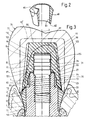
- the implant 1 consists of two originally separate, one-piece bodies, namely an elongated, metallic Base 50 and an annular and / or sleeve-shaped, still separately drawn in Fig. 2, ceramic body 60.
- the metallic body 50 forms most of the implant 1 and extends from first end 8 to the second end 9 of the implant.
- the ceramic body 60 forms the area located in the vicinity of the shoulder 21 the outer and / or peripheral surface of the implant, namely the upper portion of the peripheral surface of the trumpet-shaped Section 13, the conical shoulder surface 22 and the outer edge region of the flat annular surface 23.
- Der Metallic body 50 has at the height of the shoulder 21st a the axis 3 and the blind hole 35 enclosing annular throat 51. This is through one at the bottom the throat arranged stop surface 52 and a neck surface 53 formed or limited.
- the stop surface 52 is located approximately at the height of the transition section 39 of the Blind hole 35.
- the neck surface 53 protrudes from the stop surface 52 way up, limiting a neck of the main body and extends to the flat annular surface 23rd
- the ceramic body 60 has a lower end annular bearing surface 62 and a from this to the upper end of the ceramic body extending inner surface 63.
- the stop surface 52 of the main body 50 and the Support surface 62 of the ceramic body 60 form with the Axis 3 an at least approximately right angle, namely an exactly right angle.
- the two surfaces 52, 62 are accordingly.
- the neck surface 53 of the main body 50 and the inner surface 63 of the body 60 are at least approximately parallel to the axis, namely exactly parallel to this as well as cylindrical.
- the inner surface 63 of the ceramic Body 60 encloses the neck surface 53 of the metallic one Main body 50, for example, with small radial clearance.
- the ceramic body 60 is a binder undetachably connected to the main body 50.
- the binder consists of a thin liquid, in a thin layer Applicable adhesive, is between the two cylindrical surfaces 53, 63 arranged and connects them together.
- the two flat surfaces 52 and 62 are located for example, without interposed binder but without a gap, but may also be be connected by a binder.
- the Metallic body 50 and the ceramic body 60th form together after curing of the binder together one rigid, inseparable unity.
- the of metallic base body 50 and formed by the ceramic body 60 Peripheral surface areas of the trumpet-shaped section 13 can in the manufacture of the two bodies 50, 60 such be formed after gluing the two Body without finishing the latter practically smooth, infinitely and seamlessly connect to each other.
- Fig. 3 shows a bone 71, for example the Mandible covering this covering soft tissue 73 - i. the Gingiva - a patient and a device 75.
- the Device 75 has a trained according to FIG. 1, in the Bone 71 inserted implant, 1 a metallic one Bolt 80 and a structural member 77 and a Superstructure with a one-piece, ceramic body 90 and a crown 110 on.
- the bolt 80 and the body 90 are also visible in Fig. 4.
- the metallic bolt 80 has a threaded portion 82 with an external thread 83 and a cylindrical, threadless section 84 whose outside diameter is the same the outer diameter of the threaded portion 82 or a little greater than the latter diameter.
- a cylindrical, threadless section 84 whose outside diameter is the same the outer diameter of the threaded portion 82 or a little greater than the latter diameter.
- the cylindrical portion 84 is at least one annular groove 85th and provided for example with two or even more such.
- Between the threaded portion 82 and the cylindrical Section 84 is a concave curved in axial section annular groove available.
- the ceramic body 90 is cap-shaped and / or sleeve-shaped and has a at the bottom of the body 90th open, at the top by a ceramic material existing cover portion of the body 90 closed, axial hole 91. Its mouth section is through a tapering away from the lower end of the body 90, conical bearing surface 92 formed. This forms composite device 75 with the axis 3 the same Angle as the shoulder surface 22 and is at least on the inner area of this gap-free up. On the conical Support surface 92 follow up a cylindrical Inner surface 93 and a conical inner surface 94.
- This Inner surfaces 93, 94 enclose the generally cylindrical head portion 25 and conical head portion 27, in particular between the conical head portion and the conical inner surface 94 at most a very small Game is available.
- To the conical inner surface 94 closes an annular, radial to the axis 3 and right-angled inner surface 95, which is the end face 31 of the Implant 1 faces a smaller distance.
- To the inner end of the radial inner surface 95 closes a cylindrical inner surface 96, which is the cylindrical Section 84 of the bolt 80 with at most small game encloses.
- the upper end of the hole 91 is defined by a to most flat end surface 97 formed, the end surface facing the bolt in the distance.
- the cap-shaped, Ceramic body 90 has a generally to the axis 3rd rotationally symmetric, namely an upward tapered, conical peripheral surface 98, but with some recesses 99 distributed along the circumference provided, in which a turning tool can engage.
- the body 90 has at the upper end an end face which, in essence, i.e. apart from the recesses 99, rotationally symmetric, and also smooth, even and hole-free.
- the outer edge of the conical bearing surface 92 of the For example, ceramic body 90 has a smaller one Diameter than the outer edge of the shoulder surface 22, so that the latter still one the lower edge of the ceramic Body has 90 enclosing area.
- the crown 110 exists For example, from a gold alloy and / or porcelain and sits in the finished device firmly on the cap-shaped, ceramic body 90.
- the crown lies on the outer region of the shoulder surface 22 and closes infinitely and smoothly to the upper end of the peripheral surface of the trumpet-shaped section 13 of the implant.
- ceramic body 90 is in the uppermost cylindrical portion of the hole 91 by a binder 120, for example, a relatively viscous, thick layer Applicable cement, unsolvable with the cylindrical section 84 of the bolt 80 connected.
- the cement then fills the Ring grooves 85, and the space between the upper end of the bolt 80 and the end surface 97 of the hole 91 from. Depending on radial play may also be between the annular cylindrical peripheral surface portions of cylindrical portion 84 of the bolt and the cylindrical Inner surface 96 of the body 90 cement may be present. It was nor noted that the binder in Fig. 4 is not was presented.
- the bolt 80 and the cap-shaped, ceramic bodies 90 form after curing of the Binder 120 or cement together a rigid, inseparable unit 122.
- the metallic base 50, the metallic bolt 80 and the two ceramic bodies 60 and 90 are in manufactured a manufacturer.
- the two ceramic Body 60 and 90 are in the factory by means of the already mentioned binder, insoluble and rigid with the Base 50 or bolt 80 connected. That from the Main body 50 and the ceramic body 60 existing Implant 1 and the bolt 80 and ceramic body 90 existing unit 122 will then be considered two units For example, to a dental practice or dental clinic delivered.
- a dentist can implant 1 according to FIG. 3 to use transgigival in the mouth of a patient, so that the anchoring part 5 of the implant 1 to a large Part is anchored in a hole of the bone 71 and the upper end portion of the implant 1 from the bone protrudes.
- the attached to the base 50, ceramic Body 60 extends approximately from the crest of the bone 71 almost to the crest of the soft tissue.
- the dentist can then first with a screw a cap-shaped Attach the healing element to implant 1 until the Operation wound healed. After the healing phase, the Dentist remove the healing element and remove it from the bolt 80 and the ceramic body 90 existing unit 122 am Attach implant 1.
- the dentist can do this with a Rotary tool in the recesses 99 of the ceramic body 90th engage and the threaded portion 82 of the bolt 80 in the Screw internal thread 38 of implant 1 until the Auflege requirements 92 of the ceramic body 90 without gaps on the Shoulder surface 22 of the implant rests.
- the lower End portion of the cylindrical portion 84 of the bolt 80th sticks out at the finished device with at most small, radial play a little in the cylindrical hole section 37 of the implant 1 into it.
- the out of the bolt 80 and the ceramic body 90 existing unit 122 is then through the bolt releasably but stably connected to the implant 1.
- This Binder 125 consists for example of a Temporary cement, as is the case from dentists to temporary Attachment of provisional mounted components used and that gives a fairly firm connection, but allows the interconnected parts with a to separate power again from each other.
- the binder 125 can also come from a normal, for a permanent, Insoluble compound provided cement.
- the any existing binder 125 is in addition to still releasably screwed into the implant bolt 80 still one only with a certain force or not at all non-destructive detachable connection of the ceramic body 90 with the implant 1.
- the implant 1 and the bolt 80 and the ceramic body 90 existing unit 122 form according to their detachable or insoluble compound together a stable, rigid support.
- the dentist has to So for the creation of this support only two separate, the dentist provided units, namely the Implant 1 and unit 122, in the patient's mouth put together. This simplifies the construction of a Dentures in the mouth of a patient.
- the dentist can for the formation of a Denture an impression of the upper implant part and the Take body 90, make the crown 110 and make the Crown with unmarked cement on the ceramic body 90 and possibly attach to the shoulder surface 11.
- the dentist can the ceramic body 60th and / or the ceramic body 90 for optimizing the mold dentures still inside the patient's mouth grind in places.
- Figures 2, 3 and 4 by dot-dashed lenses indicated areas 65 and 105 of the two originally rotationally symmetrical body 60 or 90 weggeschliffen become. Since the shoulder surface 22 facing away from the end portion of the ceramic body 90, the upper, from the implant. 1 outstanding end of the bolt 80 covers, if necessary also a part of the top of the bolt covering, be ground away ceramic material.
- the bolt 80 is in both the internal thread 38 and in the cylindrical hole portion 37 of the implant 1 side supported.
- the cap-shaped ceramic body 90 is replaced by the held cylindrical portion 84 of the bolt and laterally supported. Furthermore, the body 90 is free of play and gap-free on the shoulder surface 22 of the implant and is also supported laterally from the head 7, and indeed in particular by the conical head section 27 to the upper, second end 9 of the implant 1.
- the structural element 77 Therefore, in addition to approximately axial forces, large, approximately transverse to the axis 3 directed forces on the implant transferred, without due to these forces movements of the implant. This ensures a big one Stability of the formed dentures.
- the adjacent to the dentures soft tissue 73 is after healing with the finished device at least for the most part on the peripheral surface of the annular Ceramic body 60 and is practically grown on this. Maybe there is still soft tissue on the example porcelain crown 110. On the other hand that is Soft tissue nowhere, or at least almost anywhere metallic surface of the implant. This works Inflammation of the soft tissue. If the crown 110 made of porcelain, the ceramic body 90, the formation of a shiny, color a beautiful, natural tooth corresponding crown. If the crown 110 off a metallic material, it is through the both ceramic bodies 60 and 90 against the metallic Main body 50 of the implant electrically isolated, so that no galvanically generated electric current from the crown 110 can flow to the implant 1.
- ceramic body 90 can by the knit-dotted indicated ceramic body 90 'replaced become.
- This is essentially approximately cylindrical and has at its lower end an annular bearing surface, whose outer diameter is approximately equal to or equal to Outside diameter of the shoulder surface 22 is.
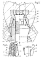
- the implant 1 of the device shown in Fig. 5 is the same as that in Figures 1 and 3 apparent implant.
- the apparent in Fig. 5 Device has, however, instead of the bolt 80 a Occlusal screw 180 and instead of the ceramic body 90th a metallic body 190.
- the screw 180 has a Threaded portion 182 and a head 183 with a Polygonal hole, for example a hexagonal hole.
- the Metallic body 190 is cap-shaped and / or sleeve-shaped and has, however, instead of an axial blind hole through axial hole 191. This is stepped and has At the bottom is a conical support surface 192 which extends to the Outside edge of the conical shoulder surface 22 of the implant the shoulder surface rests.
- the body 190 also has a conical inner surface 194, which the conical head portion 27 of the implant 1 with at most small game encloses.
- the hole 191 also has an upwardly conical expanding support surface 196, on which the head of Occlusal screw with a conical surface rests.
- the Construction element of the apparent in Fig. 5 device has again a crown 110. This is to the body 190 molded and consists, for example, as the construction element As shown in FIG. 3 in general made of porcelain or a Gold alloy.
- the metallic body 190 has one of Outside edge of the support surface 192 away upward Outside surface section, smooth and steady to the Outside surface of the ceramic body 60 connects and on then the outer surface of the crown smooth and steady adjoined.
- the crown 110 has above the head 183 of the Occlusal screw 180 indicated by dash-dotted lines, cylindrical area 132. This consists for example of one after inserting the screw 180 with an insert and / or cement or the like sealed hole and can if necessary later without damaging the rest of the crown again exposed - for example, drilled - be. This allows the occlusal screw to be released later and the crown 110 and the body 190 from the implant 1 to separate.
- the adjacent to the soft tissue surface of Device is again at least in large part formed by the ceramic body 60.
- the ceramic body 60 of the in Figures 1, 3 and 5 shown implant 1 can by the in Fig. 6 apparent, ceramic body 60 are replaced. This differs from the previously described body 60 in that at the upper end a plane, to the axis 3 has right-angled ring surface. This is located at finished implant below the in Fig. 1 from the main body 50th formed main part of the annular surface 23 or in the same Height like the latter and forms on its own or together with the annular surface formed by the base body 50 a shoulder surface 22 perpendicular to the axis 3.
- the sleeve and / or annular body 60 could also instead of the upwardly outwardly inclined peripheral surface one at least partly cylindrical or even against the top have an inwardly inclined surface.
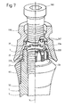
- the device shown in part in Fig. 7 has an implant 1, its anchoring part 5 and shoulder 21 the same as in the implant according to FIG. 1 are formed.
- the head 7 is formed differently than in the Fig. 1 illustrated implant.
- the generally to the axis 3 parallel and generally cylindrical head portion 25th is still provided with an external thread 226.
- the axial grooves 33 in cross section instead of arcuate for example, approximately rectangular or trapezoidal.
- the annular end face 31 along with the Distribute circumference, radial recesses or grooves 233, 234 provided, wherein a plurality of identical, first recesses or Grooves 233 and a second, wider and / or deeper Recess or groove 234 are present.
- FIG. 7 are still an occlusal screw 180 and a metallic, cap and / or sleeve-shaped body 190 can be seen.
- the latter is similar to the body 190 shown in FIG formed, but still has radially inward Projections 247th These can with at most small game in engage one of the first recesses or grooves 233 and the body 190 thereby rotatably with respect to the implant 1 in one of several rotational positions selectable rotational position position.
- the implant shown in FIG. 7 can instead of the occlusal screw 180 and the metallic Body 190 a metallic bolt with a rigid at this attached, closed up, ceramic body attached become.
- This bolt and ceramic body can be similar like the corresponding parts in FIGS. 3 and 4 be educated.
- the ceramic body has in particular no protrusions corresponding to the projections 247, so that consisting of the bolt and the ceramic body Unit screwed to the implant by turning it can be.
- the recesses or grooves 233 then have no positioning effect.
- the implant shown in FIG. 7 thus allows different types of attachment.
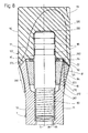
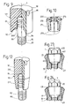
- Fig. 8 device has an implant 1, according to the left or right Figure half can be formed. Both half in the Fig. 8 illustrated implant variants have from the bottom End of the anchoring part 5 to the shoulder 21 approximately the same outer shape as that shown in Fig. 1 Implant.
- Each implant shown in Fig. 8 has in particular a generally cylindrical section 11, a trumpet-shaped section 13 and a shoulder 21 with a conical shoulder surface 22.
- the implant has a metallic body 50 on, which in the left Figurine half drawn variant also at least the most of the trumpet-shaped section 13 and the conical shoulder surface 22 forms.
- the from the outside edge the shoulder surface 22 to near the lower end of the trumpet-shaped portion 13 extending portion of Peripheral surface of the metallic base body 50 is in the left-hand variant with a sprayed on, ceramic coating 260 provided, for example, approximately 50 ⁇ m thick.
- the in the right half of Fig. 8 drawn variant of the implant has - similar to the Implant according to Figures 1 and 3 - an annular and / or sleeve-shaped, ceramic body 60, the at least the outermost part as well as the outer edge of the conical shoulder surface 22 and for example the largest Part of this or even the whole conical shoulder surface 22 forms.
- the implant shown in Fig. 8 has no the head 7 of the implant shown in Fig. 1 appropriate head.
- the axial blind hole 35 has a from Inner edge of the conical shoulder surface 22 formed mouth 36. Furthermore, the blind hole 35 between its internal thread 38 and its mouth 36 one to the latter flared, conical hole section 267.
- the apparent in Fig. 8 device further has a metallic bolt 80 and a sleeve and / or cap-shaped, ceramic body 90.
- the bolt 80 and the Body 90 can also be seen in FIG. 9.
- the bolt 80 has a threaded portion 82 and a cylindrical portion 84. The latter is near its threaded portion opposite end provided with annular grooves 85, while his the area subsequent to the thread section is slotless and has a smooth cylindrical surface.
- the illustrated in Fig. 8 ceramic body 90 in turn has an axial, open at the bottom, closed top, for the most part cylindrical hole 91 and a conical bearing surface 92, the composite at Device on the shoulder surface 22 occurs.
- the peripheral surface of the body 90 has a bottom annular, narrow upwardly widening section, at least approximately steadily to that of coating 260 formed peripheral surface portion of the implant adjoined.
- the upper, most of the peripheral surface of Body 90 is cylindrical. At the upper end of the body 90 Some recesses are 99 for attacking with one Turning tool available.
- the upper end portion of the bolt 80 protrudes as in the embodiment shown in Fig.
- FIG. 8 has another also shown separately in Fig. 10, metallic Ring 270.
- This one is at compound Device in the conical hole section 267 of the implant, encloses the cylindrical portion 84 of the bolt 80 and has a conical outer surface 271 and a cylindrical Inner surface 272.
- the conical inner surface of the hole section 267 and the conical outer surface 271 form with the axis 3 the same angle, preferably 5 ° to 10 ° and the Example is about 8 °.
- the ring is through in Fig. 10 apparent, alternately from below and above incisions cut 273 into slightly resilient segments divided.
- a deformable pressure ring 275 is arranged between the annular surface 269 of the ceramic Body 90 and the flat, upper end surface of the ring 270 .
- the bolt 80 is in turn already in the factory by the drawn in Fig. 8, but not in Fig. 9 binder 120 undetachably connected to the ceramic body 90, so that the bolt 80 and the body 90 together a solid unit 122 form.
- the pressure ring 275 and the ring 270 can also already in the factory on the bolt 80th be pushed, in which case the ring 270 slightly on the bolt clamped, but still slidable along this.
- the Implant 1 and the unit 122 with the on the bolt 80th plugged rings 271 and 275 are for example at delivered to a dentist. This can then the implant 1 Insert transgingival into the mouth of a patient. After this Healing the implant 1, the dentist, the unit 122 with the two rings 271, 275 connect to the implant 1, i.e.
- the deformable pressure ring 275 presses the ring 270th down, leaving this with its outer surface 271 stuck and practically free of play on the inner surface of the conical Extension 267 and with its inner surface 272 at the cylindrical surface of the bolt 80 rests.
- the ring 271 centered therefore the bolt and supports this between the Internal thread 38 and the mouth 36 of the blind hole 35 to almost to the mouth 36 laterally in the implant.
- the implant 1 and the unit 122 together form a stable one Support.
- the dentist may, after inserting the unit 122 in the patient's mouth if necessary at least one Grind away area 105 of the ceramic body 90 and a Crown or other superstructure build on this.
- the adjacent to the soft tissue surface of the denture is then at least to a large extent by the Peripheral surface of the ceramic transition 260 and possibly even through a section of the peripheral surface of the ceramic body 90 is formed.
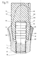
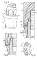
- the device shown in part in FIG. 11 has one according to the left or right half of the figure trained implant 1.
- the two half each drawn implant variants are the same as those in Fig. 8 drawn implant variants designed and have a metallic base body 50 and a ceramic Cover 260 or body 60.
- the device according to FIG. 11 also has a unit shown separately in FIG 122 with a metallic bolt 80 and a ceramic Body 90.
- the bolt has a threaded portion 82 as well a cylindrical portion 84 and is the in Fig.
- ceramic body 90 has a conical section 291 extending to the lower end of the Body 90 tapers and with device assembled fixed and free of play in the conical hole section 267 of Implant sits.
- the body 90 also has an im general cylindrical section 292 at assembled device above the implant 1 located.
- the body 90 of the illustrated in Fig. 11 Device is in contrast to the body 90 according to FIG. 8 not on the shoulder surface 22, but from this enclosed.
- the bolt 80 in turn projects into an axial, top closed hole 91 of the body 90 in and is through a Binder 120 connected to this.
- a dentist can use the unit 122 screw into the implant.
- the conical section 291 is then free of play and firmly on the inner surface of the conical hole portion 267 and is radially through this as well as axially supported.
- the contiguous Cone surfaces also provide an inhibition and clamping action, so that the unit 122 is practically unintentional can solve by itself.
- the conical could Section 291 of the body 90 additionally with a binder be fastened in the hole section 267.
- the cylindrical one Section 292 of the ceramic body 90 may, if necessary be ground so that it, for example, the in Fig. 11 dash-dotted form receives and the area 105th is ground away.
- At the conical section 292 can for Example not shown, on the shoulder surface 22 resting crown are attached.
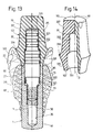
- the device partially shown in FIG. 13 has an implant 1.
- This consists exclusively of one one-piece metal body 50. This is up to but its upper, second end cylindrical possibly a not drawn external thread exhibit.
- the implant has an annular, upper-end, plane, to the axis 3 rectangular shoulder surface 22 and does not have a head rising above the shoulder surface.
- the axial blind hole 35 of the implant has a from the inner edge the shoulder surface 22 formed mouth, then to this a cylindrical hole section 37 and below an internal thread 38.
- the diameter of the cylindrical Section 37 is significantly larger than the maximum Diameter or nominal diameter of the internal thread 38.
- a hole portion 311 is provided along the Circumference distributed, inward protrusions and between has these existing spaces, the latter form axial grooves.
- the device according to FIG. 13 in turn has a Unit 122 with a metallic bolt 80 and a with this connected by a binder 120, ceramic Body 90.
- the bolt 80 has a variant in this variant Thread portion 82 and away from this in turn one first cylindrical bolt portion 321, a second cylindrical bolt portion 322 and a third cylindrical bolt portion 323.
- the second cylindrical Bolt portion 322 has a larger diameter than the two other cylindrical sections 321, 323.
- the upper Area of the second cylindrical portion 322 and the third cylindrical portion 323 are provided with annular grooves 85th Mistake.
- ceramic body 90 has an axial, in turn hole 91 completed above. This one has its on Mouth subsequent, further, cylindrical Hole section 331 and a narrower, cylindrical Hole section 332.
- the annular grooves having area of cylindrical portion 322 and the cylindrical portion 323 of the bolt sit with at most small, radial play in the hole portion 331 and 332 of the ceramic body 90 and are connected to the body 90 by the binder 120.
- the ceramic body 90 is assembled Device with its plane, perpendicular to the axis 3 Support surface 92 on the shoulder surface 22 of the implant on, wherein the two surfaces 22, 92 are the same Outer diameter and same inner diameter have.
- the on the support surface 92 subsequent section 331 of the body 90 has a slightly curved concave in axial section, after above trumpet-shaped widening peripheral surface, at composite device at least approach steadily the cylindrical peripheral surface of the implant 1 connects.
- the upper end of the trumpet-shaped portion 335 is over a concave curved in axial section and / or conical Shoulder surface 336 with an upwardly tapering, connected conical section 337. The latter is with a few recesses 99 provided.
- the implant 1 becomes subgingival in its use a bone 71 is inserted, so that the shoulder surface 22 approximately at the level of the bony crest below the Soft tissue is 73, but after cutting the Soft tissue accessible from the environment of the bone is.
- the bolt 80 is the Unit 122 screwed into the implant.
- the lower part of the second cylindrical bolt portion 322 then becomes radially approximately free of play in the cylindrical hole section 37 guided and supported during implantation of the implant Bolt portion 321, the portion 311 of the hole with a large Game and, for example, penetrates without contact.
- the Ceramic body 90 may, in turn, be strained become.
- Crown on the conical portion 337 of the body 90th be attached to the crown on the shoulder surface 336 rests.
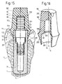
- the implant 1 of the device shown in FIG is the same as the implant according to FIG Bolt 80 of the unit 122 shown in FIG. 15 has the same as shown in Fig. 13 bolt a threaded portion 82 and three cylindrical bolt sections 321, 322, 323, however, the second cylindrical bolt portion 322 is shorter, has no grooves and a short conical bolt portion 351 with the cylindrical portion 323 is connected.
- the ceramic body 90 of FIG. 15 The apparent unit 122 is still separate in FIG. 16 and has an axial hole 91 with two cylindrical hole sections 331, 332.
- FIG. 15 Between the at the Mouth of the hole 91 subsequent, another hole section 331 and the narrower hole portion 332 are an annular, level, perpendicular to the axis 3 bearing surface 92 and a upwardly tapering, conical hole section 353 available.
- the apparent in the figures 15, 16 body 90th has similar to the drawn in Figures 13, 14 body an upwardly trumpet-shaped expanding section 335, a shoulder 336 and a conical section 337.
- the outer edge of the shoulder surface 336 is located approximately in height bearing surface 92.
- the cylindrical Bolt portion 323 and the conical bolt portion 351 of the Bolts sit in the cylindrical hole section 332 and in conical hole portion 353 of the body 90, wherein the bolt again by a binder 120 to the body 90th connected is.
- the implant 1 shown in FIG. 15 is transgingival used, so that the shoulder surface 22 of the implant above the bone 71 approximately at the level of the crest of the Soft tissue 73 is located.
- the bolt 80 in the blind hole 35 of the implant is screwed, is the second cylindrical bolt portion 322 completely in the cylindrical Hole section 37 of the implant and is approximately flush with the mouth of the hole 35.
- the ceramic body 90 is then with its bearing surface 92 on the implant shoulder surface 22 on.
- the upper end portion of the implant 1 sits with at most small, radial play in the cylindrical Hole section 331 of the body 90 and may possibly by a thin layer coatable adhesive to the body 90 connected.
- the slightly curved concave in axial section Peripheral surface of the portion 335 of the ceramic body 90th goes at the bottom of this almost stepless in the cylindrical peripheral surface of the implant over.
- the at the Soft tissue 73 adjacent surface of the device is at least for the most part by the peripheral surface of the Section 335 of the ceramic body 90 is formed.
- the device shown in Fig. 17 has an implant. 1 with a metallic base body consisting of two integral, releasably interconnected parts, namely a generally cylindrical body 360 and an in consists of this screwed intermediate bolt 370. At this is an annular and / or sleeve-shaped, ceramic Body 60 held.
- the intermediate bolt 370 is a screwed in another bolt, like the example in Figures 3 and 4 apparent bolts designated 80 is.
- a ceramic body is attached, the cap-shaped and closed at the top and like that Cap-shaped, ceramic body according to FIGS. 3 and 4 designated 90.
- the generally cylindrical body 360 is similar to the one-piece body 50 as shown in FIG. 13.
- the blind hole of the body 360 has between the internal thread 38 and the projections as well Interstices having hole portion 311 still one threadless, cylindrical hole portion 361, whose Diameter equal to the nominal diameter of the internal thread or a little bigger than this and smaller than the diameter of the at the mouth of the blind hole 35 subsequent, cylindrical hole portion 37 is.
- the intermediate bolt 370 has a screwed into the internal thread 38 Thread section 371, two cylindrical, in the Hole sections 361 and 37 guided bolt sections 372 or 373, a bunch 374 and one up from the latter protruding, cylindrical bolt portion 375.
- the collar 374 has above and below a flat ring surface and lies on the annular end surface of the body 360.
- the intermediate bolt 370 has one ending in its upper end Blind hole 377 provided, which has an internal thread 378.
- the bolt 80 is with its threaded portion in the internal thread 378 of the intermediate bolt 370 screwed.
- the sleeve-shaped, ceramic Body 60 has a flat annular surface at its upper end, for example, a little above the annular End face of the bolt 370 is located and as a shoulder surface of the Implant 1 can be considered.
- the cap-shaped, permanently attached to the bolt 80 and together with this one Unit 122 forming, ceramic body 90 is located with a level, annular bearing surface on said Ring surface of the ceramic body 60 and presses it against the collar 374.
- the sleeve-shaped, ceramic body 60 may possibly only on the intermediate bolt in this variant 370 plugged in and then at assembled device by the unit 122 am Between bolts 370 held.
- the ceramic body 60 However, for example, by a press connection and / or a binder permanently attached to the intermediate bolt 370 be.
- the metallic body 360 of the implant 1 is used subgingivally, so that the soft tissue attached to the ceramic body 60 and possibly even a little the ceramic body 90 and the collar 324 adjacent.
- the apparent in Fig. 18 device has a in general cylindrical implant 1 with a one-piece, Metallic body 50 and attached to this, ring and / or sleeve-shaped, ceramic body 60th Das Blind hole 35 has between its mouth and his Internal thread 38 analogous as in the drawn in Fig. 1 Basic body a short, cylindrical hole section 37, the at least equal to the nominal diameter or maximum Diameter of the internal thread and, for example, a little greater than the nominal thread diameter.
- the base body 50 and the ceramic body 60 have on their upper end planar annular end surfaces, of which that of the ceramic body 60, for example, a little is located above the end face of the main body and as Shoulder surface of the implant is used.
- the two annular ones However, end surfaces could also be flush with each other.
- the device according to FIG. 18 also has one Secondary part or a building element 390 with a head 391 and a bolt 392.
- the bolt 392 has one in the Internal thread 38 screwed threaded portion approximately is supported radially in the hole section 37 without play.
- the head 391 lies with an annular, flat bearing surface gap-free on the upper end surface of the ceramic body 60th on. This can be plugged and by the construction element 390th held on the body 50 or by a press connection and / or a binder insoluble in the body be attached.
- the head 391 is, for example, conical and has a blind hole opening into its upper end with a Inner thread.
- the implant 1 is transgingival in a mouth used by a patient.
- the device according to FIG. 18 serves together with at least one other, same Device and / or possibly a natural tooth for Holding and / or forming a web construction, wherein a not drawn web can be attached to the head 391.
- the implant 1 shown in FIGS. 19 and 20 is formed similar to the implant 1 and has a one-piece, metallic body 50 and an on this attached, ring and / or sleeve-shaped, ceramic body 60.
- the ceramic body 60 has on its front side at the upper, inner edge of the conical shoulder surface 22nd still a relatively wide, annular for the most part level End face 401.
- the unit 122 depicted in FIG be attached which has a bolt 80 and one at this fixed, ceramic body 90 has.
- the bolt 80 and the ceramic body 90 are similar to FIG. 3 educated.
- the ceramic body 90 is enclosed assembled device, in particular with a annular, conical bearing surface 92 on the conical Shoulder surface 22 on.
- the drawn in Fig. 20 body 90th has a annular throat 405, in the assembled at Device the or each projection 402 with game protrudes.
- the throat 405 allows the unit 122 through Rotate without hindrance by the projection 402 or the Screw projections 402 to the implant.
- the partially in Fig. 21 apparent, preferably metallic, for example gold or a gold alloy existing, cap-shaped body 410 may instead of in Fig. 20 drawn unit 122 on the implant according to the Figures 19, 20 are attached.
- the body 410 is similar as shown in Fig. 5 apparent body 190 has and has like this a continuous axial hole 411, so he analogous to the body 190 with an occlusal screw on Implant can be attached.
- the body 410 has one annular, generally conical bearing surface 412, the at least in part on the conical shoulder surface 22 of the Implant 1 rests when the body 410 at this is attached.
- the support surface 412 is equipped with several for example, twelve - evenly along the support surface distributed recesses 413 provided.
- the body 410 at Implant When the body 410 at Implant is attached as shown in FIG. 19, projects the or each Projection 402 into a recess 413 and secures the Body 410 against spins.
- the body 410 can therefore optionally in one of several rotational positions with respect to Implant 1 are rotationally fixed.
- the device shown in Fig. 22 is similar formed as the device according to FIG. 20.
- the in Fig. 22 apparent, ceramic body 60 but instead a conical shoulder surface a flat, annular Shoulder surface 22, to the inside of an annular step 423rd with a steep, slightly conical or cylindrical flank and a plane, with at least one projection 402 attached ring surface connects.
- the ceramic body 90 is designed such that it has an annular, even bearing surface gap-free on the flat shoulder surface 22 rests.
- the implant 1 shown in FIG. 23 has a similar one Outline shape like the implant according to FIGS. 19 and 20, However, has a main body 50, which consists of two originally separate parts, namely a primary part 431 and a secondary parts 432 is formed. The latter has a screwed into a blind hole of the primary part bolts and a protruding from the primary section, the forms the head 7 of the implant 1.
- the primary part 431 attached, ceramic body 60 forms the shoulder surface 22nd of the implant and has two or more along its circumference distributed protrusions 402 or cams 402.
- the implant shown in Fig. 24 has like the Implant according to FIG. 23 one of a primary part 431 and a secondary part 432 existing, metallic body 50.
- the attached to the primary part 431, ceramic body 60th has on its front side instead of projections 402 at least one recess 433 and, for example, two or more circumferentially distributed recesses 433.
- Each Recess 433 consists of a radial to the axis 3 groove.
- the implant according to FIG. 24 can optionally a unit with a bolt and a ceramic, not in the recesses engaging body or a metallic, cap-shaped body are attached, the at least one in a recess 433 engaging projection and is thereby rotationally fixed.
- the ceramic bodies 60th formed shoulder surfaces 22 in all in the figures 19, 20, 22 to 24 illustrated implants along the whole The circumference is completely smooth and either conical or flat. The attached to these implants body can therefore despite the protrusions or recesses along the whole Scope of the shoulder surfaces gapless against these.
- the Projections 402 and recesses 433 of the ceramic body 60th are located on a ring axis coaxial to the axis 3, the head of the implant in axial projection encloses.
- the projections 402 and recesses 433 have Therefore, a relatively large, radial distance from the axis 3. This contributes to accurate positioning and stable Anti-rotation of bodies attached to the implants are fixed and with the projections or recesses in Engage.
- the projections or Recesses can then, for example, in radial Direction only over the inner part of the shoulder surface extend so that the shoulder surface outside along a the entire circumference, smooth, even Section has.
- the ceramic bodies 60 of the implants according to the Figures 19 to 24 and in the preceding paragraph described implant variants can - analogous to the Implant according to FIG. 7 - several identical, first Projections or recesses and a differently sized, second projection or a differently sized, second Have recess.
- the with a screw on the implant fastenable body can then be trained with the Projections and / or recesses of the ceramic body have cooperating recesses and / or protrusions, that an implant is the body attached to it - depending of its training - either in one of several Rotary positions or only in a single rotational position rotatably positioned.
- the devices can still be changed in other ways become. It can in particular features various Embodiments are combined with each other.
- a bolt 80 and the hole 91 attached to the bolt, ceramic body 90 may be non-rotationally symmetric in cross section to the axis Have sections that with at most small game fit into each other.
- sections may be polygonal or have at least one flat surface parallel to the axis is or with this an angle different from 90 ° forms.
- the ceramic body 90 becomes non-rotatable positioned on the bolt and additionally against rotations secured relative to the bolt.
- the anchoring portion of the implant may also be at least approximately over its entire height to the lower,
- the first end of the implant is similar to a natural one Tooth root rejuvenate, but for example another Having external thread, so that the implant after the Extraction of a tooth immediately inserted into the bone can be.
- implants also in combination with others Construction elements or superstructures and other parts used, for example, to form Single teeth, bridges and dentures with several artificial ones Serve teeth.
Landscapes
- Health & Medical Sciences (AREA)
- Animal Behavior & Ethology (AREA)
- Veterinary Medicine (AREA)
- Oral & Maxillofacial Surgery (AREA)
- Orthopedic Medicine & Surgery (AREA)
- Dentistry (AREA)
- Epidemiology (AREA)
- Public Health (AREA)
- General Health & Medical Sciences (AREA)
- Life Sciences & Earth Sciences (AREA)
- Ceramic Engineering (AREA)
- Engineering & Computer Science (AREA)
- Dental Prosthetics (AREA)
- Prostheses (AREA)
- Dental Tools And Instruments Or Auxiliary Dental Instruments (AREA)
- Mechanical Operated Clutches (AREA)
Abstract
Description
Die Erfindung betrifft eine Vorrichtung zum Halten
und/oder Bilden eines Zahnersatzes gemäss dem Oberbegriff des
Anspruchs 1.The invention relates to a device for holding
and / or forming a denture according to the preamble of
Beim Zahnersatz kann es sich zum Beispiel um einen künstlichen Einzelzahn, eine Brücke oder eine mehrere Zähne aufweisende Prothese handeln.The dentures may be, for example, a artificial single tooth, a bridge or a multiple teeth acting prosthesis act.
Zahlreiche bekannte Vorrichtungen zur Bildung eines Zahnersatzes besitzen ein in einen Knochen implantierbares, aus Titan oder einer Titanlegierung bestehendes Implantat und ein im Bereich des Weichgewebes und/oder knapp oberhalb von diesem auf dem Implantat aufliegendes Aufbauelement. Ein Implantat mit einer an das Weichgewebe angrenzenden, metallischen Fläche verursacht jedoch manchmal Reizungen und Entzündungen des Weichgewebes. Das Aufbauelement besteht manchmal aus Gold oder einer Goldlegierung. Wenn Teile mit aus verschiedenen metallischen Materialien bestehenden Aussenflächen im Bereich des Weichgewebes oder in der Mundhöhle aneinanderstossen, können diese zusammen mit dem Säure enthaltenden Speichel und/oder der Gewebeflüssigkeit als galvanisches Element wirken, einen elektrischen Strom erzeugen und zusätzliche Reizungen verursachen.Numerous known devices for forming a Dentures have a bone implantable, titanium or titanium alloy implant and one in the area of the soft tissue and / or just above this resting on the implant body. One Implant with an adjacent to the soft tissue, However, metallic surface sometimes causes irritation and Inflammation of the soft tissue. The construction element consists sometimes made of gold or a gold alloy. If parts with made of different metallic materials External surfaces in the area of the soft tissue or in the The oral cavity can collide with each other Acid-containing saliva and / or tissue fluid act as a galvanic element, an electric current generate and cause additional irritation.
Bekannte Vorrichtungen haben häufig einen konischen oder zylindrischen, aus Titan oder einer Titanlegierung bestehen, aus dem Implantat herausragenden Pfeiler, auf den eine Krone oder ein anderer Teil eines Aufbauelements aufgebaut wird. Die WO 98/02110 A offenbart zum Beispiel verschiedene künstliche Zähne mit je einem Implantat, einem als "Abutment" bezeichneten Bolzen und einer Krone. Der Bolzen hat einen in ein Loch des Implantats hineinragenden Schaft und einen sich ausserhalb des Implantats befindenden, auf einer ebenen Ringfläche des Implantats aufliegenden Konus, der einen Kopf oder Pfeiler bildet. Die Krone liegt auf dem Konus des Bolzens sowie auf einem konischen oder zylindrischen Abschnitt des Implantats auf. Bei diesen künstlichen Zähnen besteht die Krone aus Keramik und/oder Metall, während das Implantat und der zum Halten der Krone dienende, in diese hineinragende Bolzen ("Abutment") aus Metall bestehen, wobei das Implantat eventuell eine Beschichtung aus Hydroxylapatatit aufweisen kann. Nach dem Einsetzen eines solchen künstlichen Zahnes in den Mund eines Patienten kann daher höchstens noch die allenfalls aus Keramik bestehende Krone beschliffen werden. Dagegen können der Bolzen oder das Implantat nicht bereits vor dem Anbringen der Krone beschliffen werden, da keine metallischen Späne in den Mund des Patienten gelangen sollten. Dies schränkt die Möglichkeit zur Anpassung der Form des künstlichen Zahns an die Formen und Abmessungen der benachbarten Zähne stark ein. Zudem können Teile des metallischen Implantats unter Umständen in Kontakt mit dem Weichgewebe im Mund des Patienten gelangen und dadurch eine starke Anlagerung von Plaque am Implantat verursachen. Ferner können eventuell Teile des metallischen Implantats bei geöffnetem Mund des Patienten von aussen sichtbar sein. Wenn eine Porzellankrone auf einen metallischen Pfeiler aufgebracht wird, schimmert der Pfeiler zudem häufig durch die Porzellankrone hindurch und verursacht einen ästhetisch störenden, matten Farbton der Porzellankrone. Es wäre zudem schwierig und praktisch kaum möglich, einen dauerhaften, gemäss der WO 98/02 110 A ausgebildeten Zahnersatz mit einer vollständig aus Keramik bestehenden Krone herzustellen. Des Weiteren offenbart die WO/02110 A keine Möglichkeit, um den Bolzen in einer definierten Drehstellung oder in ein einer von mehreren möglichen definierten Drehstellungen wählbaren Drehstellung am Implantat zu befestigen, wie es für gewisse Verwendungen wünschenswert ist.Known devices often have a conical or cylindrical, made of titanium or a titanium alloy, from the implant protruding pillar, on which a crown or another part of a building element is constructed. For example, WO 98/02110 A discloses various artificial teeth with one implant each, one as "abutment" designated bolt and a crown. The bolt has a in a hole of the implant protruding shaft and a outside the implant, on a flat surface Ring surface of the implant resting cone, which has a head or pillar forms. The crown lies on the cone of the Bolzens as well as on a conical or cylindrical Section of the implant. With these artificial teeth The crown is made of ceramic and / or metal, while the Implant and serving to hold the crown, in this protruding bolts ("abutment") made of metal, wherein the implant may have a coating Hydroxylapatatit may have. After inserting a such artificial tooth in the mouth of a patient can therefore at most still the possibly existing of ceramic Crown are ground. In contrast, the bolt or the Implant not already before attaching the crown be ground down, as no metal shavings in the mouth of the patient should arrive. This limits the possibility for adapting the shape of the artificial tooth to the molds and dimensions of the adjacent teeth strong. moreover Parts of the metallic implant may be in Get in touch with the soft tissue in the patient's mouth and thus a strong accumulation of plaque on the implant cause. Furthermore, possibly parts of the metallic Implant with open mouth of the patient from the outside being visible. If a porcelain crown on one metallic pillar is applied, the pillar shimmers also often through the porcelain crown and caused an aesthetically disturbing, dull hue of Porcelain crown. It would also be difficult and practically hardly possible, a permanent, according to WO 98/02 110 A trained dentures with a completely ceramic existing crown. Furthermore, the WO / 02110 A no way to put the bolt in one defined rotational position or in one of several possible defined rotational positions selectable rotational position to attach to the implant as it is for certain uses is desirable.
Es ist zur Vermeidung von Reizungen des Weichgewebes bekannt, zum Halten einer Krone oder eines anderen Aufbauelements dienenden Vorrichtungen im Bereich des Weichgewebes mit einem keramischen Körper zu versehen. Die US 5 310 343 A offenbart zum Beispiel Vorrichtungen mit einem metallischen Grundkörper und einem mit diesem verschraubbaren metallischen Bolzen. Der Grundkörper und der Bolzen haben im Querschnitt von keramischem Material umschlossene Abschnitte. Bei diesen bekannten Vorrichtungen ist zwischen dem am Grundkörper angeordneten, keramischen Material und dem am Bolzen angeordneten keramischen Material ein metallischer Bund des Bolzens vorhanden. Dieser metallische Bund kann höchstwahrscheinlich auch bei einem fertigen Zahnersatz, d.h. wenn zum Beispiel eine Krone an der Vorrichtung befestigt ist, in Kontakt mit dem Weichgewebe gelangen und eventuell von aussen sichtbar sein und daher die durch das keramische Material angestrebten Wirkungen beeinträchtigen. Ferner kann das keramische Material nicht zusammenhängend vom Höhenbereich des Bolzens bis zum Höhenbereich des Grundkörpers beschliffen werden, ohne auch den metallischen Bund zu beschleifen. Wie schon erwähnt sollten jedoch keine metallischen Teile innerhalb des Mundes eines Patienten beschliffen werden, weil dabei Metallspäne in den Mund des Patienten gelangen. Der Bolzen hat an seinem aus dem Grundkörper herausragenden Ende einen metallischen, bei der Endfläche nicht von keramischem Material bedeckten Endabschnitt mit einem Sechskantloch. Dies kann für gewisse Anwendungen störend sein, weil es manchmal wünschenswert wäre, das am Bolzen befestigte, keramische Material zur optimalen Anpassung der Form an die individuelle Situation auch im zentralen Bereich zu beschleifen. Wenn nach dem Einsetzen der Vorrichtung in den Mund eines Patienten ein Abdruck der Vorrichtung und der dieser benachbarten Zähne gemacht wird, kann das Sechskantloch zudem die Abdrucknahme aufwendiger und komplizierter machen, weil das Loch eventuell zuerst verschlossen werden muss. Bei den aus der US 5 310 343 bekannten Vorrichtungen haben das Loch des Grundkörpers sowie der Bolzen konische, ineinander steckende Abschnitte. Ferner bilden der Grundkörper und das an diesem angebrachte, keramische Material zusammen eine ebene Ringfläche, die bei zusammengebauter Vorrichtung einer ebene Ringfläche des Bundes zugewandt ist. Wegen der Fabrikationsungenauigkeiten können jedoch entweder nur die konischen Flächen des Grundkörper-Lochs und Bolzens oder nur die genannten ebenen Ringflächen spaltfrei aufeinander aufliegen. Wenn die konischen Abschnitte nicht spaltfrei aufeinander aufliegen, können der obere Bolzenabschnitt, das an diesem angeordnete, keramische Material und ein auf diesem aufgebauter Aufbau bezüglich des Grundkörpers quer zu dessen Achse gerichtete Mikrobewegungen ausführen. Wenn hingegen zwischen den Ringflächen ein Spalt vorhanden ist, können Mikroorganismen in diesen eindringen. Sowohl die erwähnten Mikrobewegungen als auch eindringende Mikroorganismen können die dauerhafte Befestigung der Vorrichtung im Mund eines Patienten gefährden.It is used to avoid irritation of the soft tissue known, for holding a crown or other structural element serving devices in the soft tissue area to be provided with a ceramic body. US 5,310,343 A discloses, for example, devices with a metallic one Body and a screwed with this metallic Bolt. The main body and the bolt have in cross section enclosed by ceramic material sections. In these known devices is between the on the body arranged, ceramic material and the bolt arranged ceramic material a metallic collar of the Bolzens available. This metallic waistband can most likely also in a finished denture, i. For example, if a crown is attached to the device is, get in touch with the soft tissue and possibly be visible from the outside and therefore by the ceramic Affect the material's intended effects. Furthermore, can the ceramic material discontinuous from Height range of the bolt up to the height range of the bolt Basic body are ground, without the metallic To trim the waistband. As already mentioned, however, none should metallic parts inside the mouth of a patient be ground, because while doing metal shavings in the mouth of the Patients arrive. The bolt has at his from the Main body protruding end of a metallic, at the End surface not covered by ceramic material End section with a hexagonal hole. This may be for certain Applications be annoying because sometimes desirable would be, attached to the bolt, ceramic material for optimal adaptation of the shape to the individual situation also in the central area to grind. If after the Insertion of the device in the mouth of a patient Impression of the device and of these adjacent teeth is made, the hexagon hole can also take the impression more complicated and complicated because the hole may be must be closed first. In the US 5,310,343 known devices have the hole of the body as well the bolt conical, nested sections. Further form the main body and attached to this, ceramic material together a flat annular surface, which at assembled device of a flat annular surface of the Turned federal. Because of manufacturing inaccuracies However, either only the conical surfaces of the Basic body hole and bolt or just the aforementioned levels Ring surfaces rest on each other without gaps. If the conical sections do not lie on each other without a gap, can the upper bolt portion, which arranged on this, ceramic material and a built-up on this structure directed with respect to the body transversely to its axis Perform micromotion. If, however, between the Ring surfaces a gap exists, can be microorganisms penetrate into these. Both the mentioned micro-movements as well as invading microorganisms can be the permanent ones Attachment of the device in the mouth of a patient compromise.
Die FR 2 745 998 A offenbart Vorrichtungen mit einem metallischen Implantat, einem ringförmigen Keramik-Körper und einer Suprakonstruktion. Das Implantat hat ein axiales Loch mit einem Innengewinde und einem konischen Lochabschnitt. Der Keramik-Körper hat einen ungefähr zylindrischen Hauptabschnitt und einen von diesem weg nach unten vorstehenden konischen Abschnitt, der bei zusammengebauter Vorrichtung in den konischen Lochabschnitt des Implantats hineinragt. Bei der in Fig. 1 ersichtlichen Vorrichtung besteht die Suprakonstruktion aus einem einstückigen Bolzen, der einen Schaft mit einem in das Innengewinde des Implantats einschraubbaren Aussengewinde und einen Oberteil mit einem sechseckförmigen Abschnitt sowie einem sich nach oben verjüngenden Endabschnitt zum Halten eines Aufbauelements hat. Bei zusammengebauter Vorrichtung ragt der Bolzen mit einem konischen Abschnitt in einen konischen Lochabschnitt des Keramik-Körpers hinein und drückt den Keramik-Körper gegen das Implantat. Bei der in Fig. 2 dargestellten Vorrichtung ist der einstückige Bolzen durch zwei separate Teile, nämlich eine Hülse und eine Schraube, ersetzt. Die Hülse hat einen konischen Abschnitt der bei zusammengebauter Vorrichtung in einen konischen Lochabschnitt des Keramik-Körpers hineinragt. Bei zusammengebauter Vorrichtung drückt der Kopf der Schraube die metallische Hülse gegen den Keramik-Ring, der dadurch gegen das Implantat gedrückt wird. Der konische Abschnitt der metallischen Hülse hat zwei Nocken, die in Ausnehmungen des konischen Lochabschnitts des Keramik-Körpers eingreifen. Der konische Abschnitt des letzteren hat ebenfalls zwei Nocken, die in Ausnehmungen des konischen Lochabschnitts des Implantats eingreifen. Bei beiden in den Zeichnungen der FR 2 745 998 A dargestellten Vorrichtungen besteht der oberste, sich nach oben verjüngende Teil der Suprakonstruktion - d.h. der obere Endabschnitt des Bolzens bzw. die separate Hülse - aus Metall und kann daher nicht im Mund des Patienten beschliffen werden, ohne dass Metallspäne in den Mund des Patienten gelangen. Wenn eine Porzellankrone auf den sich nach oben verjüngenden Teil der Suprakonstruktion aufgebracht wird, kann dieser metallische Teil zudem durch die Krone hindurchschimmern und ästhetisch störend sein. Da das Implantat und der Keramik-Körper sowie der letztere und der Oberteil des Bolzens (Fig. 1) bzw. die metallische Hülse (Fig. 2) einander zugewandte, ebene Ringflächen haben, liegen zudem normalerweise bei beiden in der FR 2 745 998 A offenbarten Vorrichtungen analog wie bei den aus der US 5 310 343 A bekannten Vorrichtungen entweder nur die konischen Flächen oder nur die ebenen Ringflächen der aufeinanderfolgenden Teile spaltfrei aufeinander auf, was zu analogen Nachteilen wie bei der US 5 310 343 A führt. Die aus der FR 2 745 998 bekannten Vorrichtungen haben des Weiteren noch den Nachteil, dass die Anordnung eines Keramik-Körpers zwischen dem oberen Ende des Implantats und dem zum Eingreifen in ein Aufbauelement, z. B. eine Krone, bestimmten, sich nach oben verjüngenden Teil der Suprakonstruktion einem relativ langen Helelarm zwischen dem oberen Ende des Implantats und dem in ein Aufbauelement eingreifenden Teil ergibt. Insbesondere wenn ungefähr quer zum Implantat gerichtete Kräfte auf das Aufbauelement einwirken, beeinträchtigt der genannte Hebelarm die Stabilität der Verbindung eines Aufbauelements mit dem Implantat. Ferner bildet der zum Halten eines Aufbauelements bestimmten Teil der Suprakonstruktion bis zu seinem unteren Ende einen ziemlich kleinen Winkel mit der Achse des Implantats und der Suprakonstruktion. Wenn eine Krone am unteren Ende einigermassen glatt an den auf sie folgenden Abschnitt der Vorrichtung anschliessen soll, muss die Krone dort in einen sehr dünnen Rand auslaufen, der leicht ausbricht.FR 2 745 998 A discloses devices with a metallic implant, an annular ceramic body and a superstructure. The implant has an axial hole with an internal thread and a conical hole section. Of the Ceramic body has a roughly cylindrical main section and one projecting downwardly therefrom conical section, which in assembled device in protrudes the conical hole portion of the implant. at the apparent in Fig. 1 device consists of Superstructure of a one-piece bolt, the one Shank with a in the internal thread of the implant screwable external thread and a top with a hexagonal section as well as one upwards tapered end portion for holding a structural member Has. When the device is assembled, the bolt protrudes a conical section in a conical hole section of the ceramic body and pushes the ceramic body against the implant. In the illustrated in Fig. 2 Device is the one-piece bolt through two separate Parts, namely a sleeve and a screw replaced. The Sleeve has a conical section when assembled Device in a conical hole portion of the ceramic body protrudes. Press in assembled device the head of the screw the metallic sleeve against the Ceramic ring, which is pressed against the implant. The conical section of the metallic sleeve has two Cams, which are in recesses of the conical hole section of the Intervene ceramic body. The conical section of the The latter also has two cams, which are in recesses of the engage the conical hole section of the implant. at both shown in the drawings of FR 2 745 998 A. Devices consists of the uppermost, tapering upwards Part of the superstructure - i. the upper end portion of Bolzens or the separate sleeve - made of metal and therefore can can not be ground in the patient's mouth without Get metal chips into the patient's mouth. When a Porcelain crown on the upwardly tapering part of the Supraconstruction is applied, this can be metallic Part also shimmer through the crown and aesthetically be disturbing. Because the implant and the ceramic body as well the latter and the upper part of the bolt (FIG. 1) or the metallic sleeve (Fig. 2) facing each other, level Ring surfaces have, are also usually in both in FR 2 745 998 A disclosed devices analogous to the known from US 5,310,343 A devices either only the conical surfaces or only the flat ring surfaces of the successive parts without gaps on each other, what to analog disadvantages as in US 5,310,343 A leads. From FR 2 745 998 known devices further have still the disadvantage that the arrangement of a ceramic body between the top of the implant and the to Intervention in a structural element, for. A crown, upwardly tapering part of the superstructure a relatively long hello arm between the upper end of the implant and in a building element engaging part results. Especially if about cross directed to the implant forces on the body act, the mentioned lever affects the Stability of the connection of a structural element with the Implant. Further, the forms for holding a building element certain part of the superstructure down to its lower End a pretty small angle with the axis of the Implant and the superstructure. If a crown on the lower end reasonably smooth on the next to her Section of the device, the crown must leak into a very thin edge there, which is easy breaks out.
Der Erfindung liegt die Aufgabe zugrunde, Nachteile der bekannten Vorrichtungen zu vermeiden und insbesondere eine Vorrichtung zu schaffen, die nach dem Einsetzen in einen Mund eines Patienten eine schnelle und einfache Abdrucknahme bzw. Abformung ermöglicht und deren aus dem Knochen herausragenden Teile problemlos soweit als erwünscht innerhalb vom Mund des Patienten beschliffen werden können. Die Vorrichtung soll ferner vorzugsweise ermöglichen, dass keine Mikroorganismen zwischen dem Grundkörper des Implantats und dem an diesem befestigten, keramischen Körper eindringen können und dass der am Implantat befestigbare, keramische Körper im befestigten Zustand sehr stabil mit dem metallischen Grundkörper verbunden ist, so dass dieser keramische Körper auch unter der Einwirkung von grossen, ungefähr quer zur Achse des Grundkörpers einwirkenden Kräften möglichst keine Bewegungen gegenüber dem Grundkörper ausführt. Ferner soll die Vorrichtung bei der Bildung eines Zahnersatzes im Mund eines Patienten aus möglichst wenig separaten Teilen zusammensetzbar sein.The invention is based on the object disadvantages of to avoid known devices and in particular a Device to create after insertion into a mouth a patient a quick and easy impression or Impression allows and their protruding from the bone Parts as far as desired within the mouth of the Patients can be ground. The device should further preferably allow no microorganisms between the body of the implant and the at this attached, ceramic body can penetrate and that the implantable ceramic body in the implant fastened state very stable with the metallic Body is connected so that this ceramic body also under the influence of large, approximately across the Axis of the body acting forces as possible Performs movements relative to the base body. Furthermore, should the device in the formation of a denture in the mouth a patient from as few separate parts as possible be composable.
Diese Aufgabe wird ausgehend von der FR 2 745 998 A durch
eine Vorrichtung gelöst, die gemäss der Erfindung die
Merkmale des Anspruchs 1 aufweist.This object is based on FR 2 745 998 A
a device solved according to the invention the
Features of
Vorteilhafte Ausgestaltungen der Vorrichtung gehen aus den abhängigen Ansprüchen hervor.Advantageous embodiments of the device go out the dependent claims.
Die Vorrichtung ermöglicht eine starre, stabile und dauerhafte Verbindung des mit einem Bolzen oder einer Schraube befestigbaren, keramischen Körpers mit dem metallischen Grundkörper. Ferner muss ein Zahnarzt für die Bildung eines Zahnersatzes im Mund eines Patienten nur wenig separate Teile zusammensetzen.The device allows a rigid, stable and permanent connection of the with a bolt or a Screw fastened, ceramic body with the metallic body. Furthermore, a dentist needs for the Forming a denture in the mouth of a patient only a little assemble separate parts.
Die erfindungsgemässe Ausbildung der Vorrichtung ermöglicht nach dem Einsetzen der Vorrichtung in einen Mund eines Patienten eine schnelle und einfache Abdrucknahme, d.h. Abformung der aus dem Knochen herausragenden und das Weichgewebe durchdringenden Teile der Vorrichtung. Wenn das Loch des am Implantat befestigbaren, keramischen Körpers als Sacklch ausgebildet und dieser keramische Körper mit einem in dessen Sackloch hineinragenden Bolzen am Implantat befestigt wird, ist es insbesondere nicht nötig, für die Abdrucknahme irgend ein Loch des am Bolzen befestigten, keramischen Körpers und/oder des Bolzens selbst vorübergehend abzudecken. Ferner kann nötigenfalls auch der zentrale, das aus dem Grundkörper herausragende Bolzenende bedeckende Abschnitt des am Bolzen befestigten, keramischen Körpers im Mundbereich des Patienten beschliffen werden.The inventive design of the device allows after inserting the device in a mouth a patient's quick and easy impression taking, i. Impression of the bone protruding and the Soft tissue penetrating parts of the device. If that Hole of the implantable on the implant, ceramic body as Sacklch trained and this ceramic body with a in whose blind hole attaches protruding bolts on the implant In particular, it is not necessary for taking the impression any hole of ceramic, attached to the bolt Body and / or the bolt itself temporarily cover. Furthermore, if necessary, the central, the from the Main body protruding bolt end covering section of the attached to the bolt, ceramic body in the mouth area of the Patients are ground.
Bei einer vorteilhaften Ausgestaltung der Vorrichtung hat der metallischen Grundkörper einen axialen, im Querschnitt von keramischem Material umschlossenen Abschnitt. Dieses keramische Material besteht beispielsweise aus einem ursprünglich separaten, keramischen Körper. Der das genannte keramische Material bildende, allenfalls am Grundkörper befestigte keramische Körper und der mit einem Bolzen am Implantat befestigbare, keramische Körper sind beispielsweise durch ein Bindemittel direkt mit dem Grundkörper bzw. dem Bolzen verbunden. Das Bindemittel kann abhängig von der Ausbildung der miteinander zu verbindenden Teile aus einem dünnflüssigen, in einer dünnen Schicht auftragbaren Klebstoff oder aus einem relativ viskosen Klebstoff bzw. Zement bestehen, der zum Ausfüllen mindestens eines relativ grossen Zwischenraums geeignet ist. Der Klebstoff und/oder Zement kann beim Verbinden der Teile beispielsweise bei normaler Raumtemperatur aushärten oder zum Aushärten erwärmt werden. Der bzw. jeder keramische Körper kann möglicherweise statt durch einen Klebestoff bzw. Zement durch eine Hartlöt-Verbindung mit dem metallischen Grundkörper bzw. Bolzen verbunden sein. In diesem Fall besteht das Bindemittel dann aus einem Hartlot, das beim Verbinden des keramischen Körpers mit dem metallischen Grundkörper oder Bolzen vorübergehend erhitzt und geschmolzen wird. Das Bindemittel soll in allen Fällen biokompatibel, nicht toxisch und gut mit dem Knochen und Weichgewebe von Patienten verträglich sein. Der keramische Körper kann ferner zusammen mit dem Grundkörper oder dem Bolzen einen Press-Sitz bilden und statt durch ein Bindemittel oder zusätzlich zu einem solchen durch eine Press-Verbindung mit dem Grundkörper bzw. Bolzen verbunden sein. In an advantageous embodiment of the device has the metallic base body an axial, in cross section enclosed by ceramic material section. This Ceramic material consists for example of a originally separate, ceramic body. The said ceramic material forming, possibly at the base body attached ceramic body and the one with a bolt on Implant attachable, ceramic bodies are for example by a binder directly to the main body or the Bolt connected. The binder may depend on the Training the parts to be joined together from a low-viscosity, can be applied in a thin layer adhesive or from a relatively viscous adhesive or cement exist, to fill at least a relatively large Space is suitable. The glue and / or cement can when connecting the parts, for example, at normal Cure room temperature or heated to cure. The or each ceramic body may possibly take place through a cement through a braze joint with the metallic body or bolt be connected. In this case, the binder then exists from a brazing filler, which when connecting the ceramic body with the metallic body or bolt temporarily heated and melted. The binder should in all Cases biocompatible, non-toxic and good with the bone and soft tissue of patients. Of the Ceramic body can also be used together with the main body or the bolt form a press-fit and instead of a Binder or in addition to such by a Press connection connected to the main body or bolt be.
Der bzw. jeder keramische Körper kann separat - d.h. vom Grundkörper und allfälligen Bolzen getrennt - beispielsweise aus einer Teilchen aufweisenden, plastisch verformbaren, mehr oder weniger gut fliessfähigen Masse mit Hilfe einer Gussform oder dergleichen derart geformt werden, dass er mindestens im Wesentlichen rotationssymmetrisch zu einer Achse ist. Der geformte Körper wird dann, bevor er mit dem metallischen Grundkörper bzw. mit dem eventuell vorhandenen Bolzen verbunden wird, in üblicher Weise erhitzt und versintert. Wenn zwei keramische Körper vorhanden sind, kann einer oder jeder von diesen bei seiner Verwendung zur Bildung eines Zahnersatzes nötigenfalls noch im Mund eines Patienten stellenweise von einem Zahnarzt beschliffen und dadurch bei der Herstellung eines Aufbauelements bzw. einer Suprakonstruktion individuell geformt werden.The or each ceramic body may be separately - i. from Main body and any bolts separated - for example from a particle-containing, plastically deformable, more or less easily flowable mass with the help of a mold or the like are formed so as to be at least in Is substantially rotationally symmetric to an axis. Of the Shaped body then becomes, before it with the metallic one Basic body or with the possibly existing bolt is heated in the usual way heated and sintered. If two ceramic bodies are present, one or more each of these when used to form a Dentures if necessary still in the mouth of a patient Partially ground by a dentist and thereby the production of a structural element or a Supraconstruction can be shaped individually.
Das vorzugsweise unmittelbar am Grundkörper befestigte, keramische Material oder mindestens ein Teil von diesem kann ferner einen unlösbar mit dem Grundkörper verbundenen, keramischen Überzug bilden. Der keramische Überzug kann unlösbar auf einen Bereich des metallischen Grundkörpers aufgebracht, beispielsweise aufgesprüht werden. Dieser Überzug kann aus einer dünnen Schicht bestehen, deren Dicke beispielsweise nur höchstens 100 µm und zum Beispiel ungefähr 50 µm beträgt.The preferably attached directly to the body, ceramic material or at least a part of this can Furthermore, an inseparably connected to the body, form ceramic coating. The ceramic coating can indissoluble on a region of the metallic body applied, for example, be sprayed. This Coating may consist of a thin layer whose thickness for example, only at most 100 microns and, for example, approximately 50 microns.
Der metallische Grundkörper und der allenfalls im Loch des Grundkörpers befestigte, metallische Bolzen kann beispielsweise aus Titan oder einer Titanlegierung bestehen. Der bzw. jeder keramische Körper und/oder der keramische Überzug besteht vorzugsweise aus Oxidkeramik, beispielsweise aus Aluminiumoxid und/oder Magnesiumoxid und/oder Zirkoniumdioxid, und ist vorzugsweise elektrisch isolierend. The metallic base body and possibly in the hole of the main body fastened, metallic bolts can for example, titanium or a titanium alloy. The or each ceramic body and / or the ceramic Coating is preferably made of oxide ceramics, for example from alumina and / or magnesia and / or Zirconia, and is preferably electrically insulating.
Der Erfindungsgegenstand und weitere Vorteile von diesem
werden anschliessend anhand in den Zeichnungen dargestellter
Ausführungsbeispiele erläutert. Dabei zeigen die
Zu den nachfolgend beschriebenen Ausführungsbeispielen wird darauf hingewiesen, dass einander entsprechende, identische oder ähnliche Teile der verschiedenen Ausführungsbeispiele jeweils mit der gleichen Bezugsnummer bezeichnet werden.For the embodiments described below It is noted that corresponding, identical or similar parts of the different ones Embodiments each with the same reference number be designated.
Das in Fig. 1 ersichtliche Implantat 1 ist im allgemeinen
rotationssymmetrisch zu einer Achse 3 und weist unten eine
zum Verankern in einem Knochen eines Unter- oder Oberkiefers
bestimmte Verankerungspartie 5 und oben einen zum Herausragen
aus dem Knochen bestimmten Kopf 7 auf. Die einander
abgewandten, freien Enden der Verankerungspartie und des
Kopfs bilden das erste Ende 8 bzw. das zweite Ende 9 des
Implantats 1. Die Verankerungspartie 5 hat von unten nach
oben einen im allgemeinen zylindrischen Abschnitt 11 und
einen sich von diesem weg erweiternden, trompetenförmigen
Abschnitt 13, dessen Aussenfläche stetig und glatt an die
Aussenfläche des im allgemeinen zylindrischen Abschnitts 11
anschliesst. Der im allgemeinen zylindrische Abschnitt 11 ist
mit einem Aussengewinde 15 mit einer schraubenlinienförmigen
Rippe 16 versehen. Das Aussengewinde 15 ist beispielsweise
selbstschneidend ausgebildet. Die Verankerungspartie ist in
der Nähe ihres unteren Endes mit mehreren, beispielsweise
drei um die Achse 3 herum verteilten, länglichen Nuten
und/oder Löchern 17 versehen, welche die
schraubenlinienförmige Rippe 16 des Aussengewindes kreuzen.The apparent in Fig. 1
Am oberen, weiteren Ende des trompetenförmigen Abschnitts
13 ist eine Schulter 21 mit einer vom ersten Ende 8 weg nach
oben gegen innen geneigten, konischen Schulterfläche 22
vorhanden. Diese bildet mit der Achse 3 einen Winkel von 40°
bis 50° und beispielsweise 45°. An das obere, engere Ende der
konischen Schulterfläche 22 schliesst eine ebene, zur Achse 3
rechtwinklige Ringfläche 23 an.At the top, further end of the trumpet-shaped
Der Kopf 7 ragt von der Ringfläche 23 weg nach oben, ist
im allgemeinen zur Achse 3 rotationssymmetrisch und hat einen
im Wesentlichen zur Achse 3 parallelen, im allgemeinen
zylindrischen Kopfabschnitt 25 sowie einen sich von diesem
weg nach oben zum freien Ende des Kopfs und damit zum zweiten
Ende 9 des ganzen Implantats hin verjüngenden, im allgemeinen
konischen Kopfabschnitt 27. Die beiden Kopfabschnitte 25, 27
haben je eine zur Achse rotationssymmetrische, nämlich
zylindrische bzw. konische Hüllfläche. Der maximale
Durchmesser des Kopfs ist kleiner als die Durchmesser des
Aussenrandes sowie auch des Innenrandes der konischen
Schulterfläche 22. Die konische Hüllfläche des im allgemeinen
konischen Kopfabschnitts 27 bildet mit der Achse 3 einen
Winkel, der kleiner ist als der von der konischen
Schulterfläche 22 mit der Achse gebildete Winkel und
vorzugsweise 15° bis 25°, nämlich und zum Beispiel ungefähr
20° beträgt. Der zur Achse parallele Kopfabschnitt 25 ist
durch eine im Axialschnitt konkav gebogene Ringnut 29 vom
oberen Ende der Schulter 21 abgegrenzt. Der Kopf hat eine
Umfangsfläche 30 und an seinem freien Ende eine das zweite
Ende 9 des Implantats bildende ebene, ringförmige Stirnfläche
31. Die Umfangsfläche 30 des Kopfs 7 weist um die Achse herum
abwechselnd aufeinanderfolgende Vorsprünge und Zwischenräume
auf. Die Zwischenräume bestehen aus axialen Nuten 33, die im
Querschnitt beispielsweise bogenförmig sind, jedoch statt
dessen V-förmig, trapezförmig oder rechteckförmig sein
könnten. Dabei sind vorzugsweise mehrere identisch
ausgebildete sowie bemessene, erste Nuten sowie eine breitere
und/oder tiefere, zweite Nut vorhanden. Die im Querschnitt
tiefsten Bereiche der Nuten 33 erstrecken sich über die ganze
Länge des zur Achse 3 parallelen Kopfabschnitts 25 und
mindestens annähernd sowie beispielsweise genau bis zum
dünneren Ende des konischen Kopfabschnitts 27 und also auch
bis zum zweiten Ende 9 des ganzen Implantats.The
Das Implantat 1 ist mit einem zur Achse 3 koaxialen
Sackloch 35 versehen. Dieses besitzt eine sich beim zweiten
Ende 9 befindende, von der ringförmigen Stirnfläche 31
umschlossene Mündung 36 und von dieser weg nach unten der
Reihe nach kurzen, glatten, ersten zylindrischen
Lochabschnitt 37, ein beispielsweise metrisches Innengewinde
38, einen Übergangsabschnitt 39, einen zweiten zylindrischen,
glatten, d.h. gewindelosen Lochabschnitt 40 und einen Grund
41. Das untere, weiter von der Mündung entfernte Ende des
Innengewindes 38 befindet sich innerhalb des sich
erweiternden, trompetenförmigen Abschnitts 13 des Implantats.
Der Durchmesser des zweiten, zylindrischen Lochabschnitts 40
ist kleiner als derjenige des ersten zylindrischen
Lochabschnitt 37 und ungefähr gleich dem Kerndurchmesser des
Innengewindes. Der Übergangsabschnitt 39 besteht aus einer
ziemlich flachen Ringnut und hat eine Fläche, die im
Axialschnitt stetig gebogen ist und stetig in die
zylindrische Fläche des zweiten, zylindrischen Lochabschnitts
übergeht. Der Grund 41 verjüngt sich zu seiner tiefsten
Stelle hin und ist durch eine im Axialschnitt gebogene Fläche
begrenzt, die stetig und glatt mit der Fläche des zweiten
zylindrischen Lochabschnitts 40 zusammenhängt.The
Das Implantat 1 besteht aus zwei ursprünglich separaten,
einstückigen Körpern, nämlich einem länglichen, metallischen
Grundkörper 50 und einem ringförmigen und/oder
hülsenförmigen, noch separat in Fig. 2 gezeichneten,
keramischen Körper 60. Der metallische Grundkörper 50 bildet
den grössten Teil des Implantats 1 und erstreckt sich vom
ersten Ende 8 bis zum zweiten Ende 9 des Implantats. Der
metallische Grundkörper 50 bildet insbesondere auch
mindestens den grössten Teil der Verankerungspartie 5, das
ganzen Aussengewinde 15 sowie den ganzen Kopf 7 und die ganze
Begrenzung des Sacklochs 35. Der keramische Körper 60 bildet
den sich in der Umgebung der Schulter 21 befindenden Bereich
der Aussen- und/oder Umfangsfläche des Implantats, nämlich
den oberen Bereich der Umfangsfläche des trompetenförmigen
Abschnitts 13, die konische Schulterfläche 22 und den
äusseren Randbereich der ebenen Ringfläche 23. Der
metallische Grundkörper 50 hat in der Höhe der Schulter 21
eine die Achse 3 und das Sackloch 35 umschliessende,
ringförmige Kehle 51. Diese ist durch eine am unteren Ende
der Kehle angeordnete Anschlagfläche 52 und eine Halsfläche
53 gebildet bzw. begrenzt. Die Anschlagfläche 52 befindet
sich ungefähr in der Höhe des Übergangsabschnitts 39 des
Sacklochs 35. Die Halsfläche 53 ragt von der Anschlagfläche
52 weg nach oben, begrenzt einen Hals des Grundkörpers und
erstreckt sich bis zur ebenen Ringfläche 23.The
Der keramische Körper 60 hat am unteren Ende eine
ringförmige Auflagefläche 62 und eine sich von dieser bis zum
oberen Ende des keramische Körpers erstreckende Innenfläche
63. Die Anschlagfläche 52 des Grundkörpers 50 und die
Auflagefläche 62 des keramischen Körpers 60 bilden mit der
Achse 3 einen mindestens ungefähr rechten Winkel und nämlich
einen genau rechten Winkel. Die beiden Flächen 52, 62 sind
dementsprechend eben. Die Halsfläche 53 des Grundkörpers 50
und die Innenfläche 63 des Körpers 60 sind mindestens
ungefähr parallel zur Achse und nämlich genau parallel zu
dieser sowie zylindrisch. Die Innenfläche 63 des keramischen
Körpers 60 umschliesst die Halsfläche 53 des metallischen
Grundkörpers 50 zum Beispiel mit kleinen radialem Spiel. Der
radiale Abstand der Innenfläche 63 von der Halsfläche 53
beträgt vorzugsweise höchstens 200 µm und zum Beispiel 5 µm
bis 50 µm. Der keramische Körper 60 ist durch ein Bindemittel
unlösbar mit dem Grundkörper 50 verbunden. Das Bindemittel
besteht aus einem dünnflüssigen, in dünner Schicht
auftragbaren Klebestoff, ist zwischen den beiden
zylindrischen Flächen 53, 63 angeordnet und verbindet diese
miteinander. Die beiden ebenen Flächen 52 und 62 liegen
beispielsweise ohne dazwischen angeordnetes Bindemittel
spaltfrei aufeinander auf, können aber eventuell ebenfalls
durch ein Bindemittel miteinander verbunden sein. Der
metallische Grundkörper 50 und der keramische Körper 60
bilden nach dem Aushärten des Bindemittels zusammen eine
starre, untrennbare Einheit. Die von metallischen Grundkörper
50 und vom keramischen Körper 60 gebildeten
Umfangsflächenbereiche des trompetenförmigen Abschnitts 13
können bei der Herstellung der beiden Körper 50, 60 derart
ausgebildet werden, dass sie nach dem Verkleben der beiden
Körper ohne Nachbearbeitung der letzteren praktisch glatt,
stufenlos und fugenlos aneinander anschliessen.The
Die Fig. 3 zeigt einen Knochen 71, beispielsweise den
Unterkiefer, das diesen bedeckende Weichgewebe 73 - d.h. die
Gingiva - eines Patienten und eine Vorrichtung 75. Die
Vorrichtung 75 weist ein gemäss Fig. 1 ausgebildetes, in den
Knochen 71 eingesetztes Implantat, 1 einen metallischen
Bolzen 80 und ein Aufbauelement 77 bzw. eine
Suprakonstruktion mit einem einstückigen, keramischen Körper
90 sowie einer Krone 110 auf. Der Bolzen 80 und der Körper 90
sind auch in Fig. 4 ersichtlich.Fig. 3 shows a
Der metallische Bolzen 80 hat einen Gewindeabschnitt 82
mit einem Aussengewinde 83 und einen zylindrischen,
gewindelosen Abschnitt 84, dessen Aussendurchmesser gleich
dem Aussendurchmesser des Gewindeabschnitts 82 oder ein wenig
grösser als der letztgenannte Durchmesser ist. Der
zylindrische Abschnitt 84 ist mit mindestens einer Ringnut 85
und beispielsweise mit zwei oder noch mehr solchen versehen.
Zwischen dem Gewindeabschnitt 82 und dem zylindrischen
Abschnitt 84 ist eine im Axialschnitt konkav gebogene Ringnut
vorhanden.The
Der keramische Körper 90 ist kappenförmig und/oder
hülsenförmig und hat ein am unteren Ende des Körpers 90
offenes, am oberen Ende durch einen aus keramischen Material
bestehenden Deckabschnitt des Körpers 90 geschlossenes,
axiales Loch 91. Dessen Mündungsabschnitt ist durch eine sich
von unteren Ende des Körpers 90 weg nach oben verjüngende,
konische Auflagefläche 92 gebildet. Diese bildet bei
zusammengesetzter Vorrichtung 75 mit der Achse 3 dem gleichen
Winkel wie die Schulterfläche 22 und liegt mindestens auf dem
inneren Bereich von dieser spaltfrei auf. Auf die konische
Auflagefläche 92 folgen nach oben eine zylindrische
Innenfläche 93 und eine konische Innenfläche 94. Diese
Innenflächen 93, 94 umschliessen den im allgemeinen
zylindrischen Kopfabschnitt 25 bzw. konischen Kopfabschnitt
27, wobei insbesondere zwischen dem konischen Kopfabschnitt
und der konischen Innenfläche 94 höchstens ein sehr kleines
Spiel vorhanden ist. An die konischen Innenfläche 94
schliesst eine ringförmige, zur Achse 3 radiale sowie
rechtwinklige Innenfläche 95 an, die der Stirnfläche 31 des
Implantats 1 in kleineren Abstand gegenübersteht. An das
innere Ende der radialen Innenfläche 95 schliesst eine
zylindrische Innenfläche 96 an, die dem zylindrischen
Abschnitt 84 des Bolzens 80 mit höchstens kleinen Spiel
umschliesst. Das obere Ende des Lochs 91 ist durch eine zum
grössten Teil ebene Endfläche 97 gebildet, die der Endfläche
des Bolzen im Abstand gegenübersteht. Der kappenförmige,
keramische Körper 90 hat eine im allgemeinen zur Achse 3
rotationssymmetrische, nämlich eine sich nach oben
verjüngende, konische Umfangsfläche 98, ist jedoch mit
einigen entlang dem Umfang verteilten Ausnehmungen 99
versehen, in die ein Drehwerkzeug eingreifen kann. Der Körper
90 hat am oberen Ende eine Stirnfläche, die im Wesentlichen,
d.h. abgesehen von den Ausnehmungen 99, rotationssymmetrisch,
und ferner glatt, eben sowie lochfrei ist.The
Der Aussenrand der konischen Auflagefläche 92 des
keramischen Körpers 90 hat beispielsweise einen kleineren
Durchmesser als der Aussenrand der Schulterfläche 22, so dass
die letztere noch einen den unteren Rand des keramischen
Körpers 90 umschliessenden Bereich hat. Die Krone 110 besteht
zum Beispiel aus einer Goldlegierung und/oder aus Porzellan
und sitzt bei der fertigen Vorrichtung fest auf dem
kappenförmigen, keramischen Körper 90. Die Krone liegt auf
dem äusseren Bereich der Schulterfläche 22 auf und schliesst
stufenlos sowie glatt an das obere Ende der Umfangsfläche des
trompetenförmigen Abschnitt 13 des Implantats an. Der
kappenförmige, keramische Körper 90 ist im obersten
zylindrischen Abschnitt des Lochs 91 durch ein Bindemittel
120, beispielsweise einen relativ viskosen, in dicker Schicht
auftragbaren Zement, unlösbar mit dem zylindrischen Abschnitt
84 des Bolzens 80 verbunden. Der Zement füllt dann die
Ringnuten 85, und den Zwischenraum zwischen dem oberen Ende
des Bolzens 80 sowie der Endfläche 97 des Lochs 91 aus.
Abhängig von radialen Spiel kann eventuell auch noch zwischen
den ringförmigen, zylindrischen Umfangsflächenabschnitten des
zylindrischen Abschnitts 84 des Bolzens und der zylindrischen
Innenfläche 96 des Körpers 90 Zement vorhanden sein. Es sei
noch angemerkt, dass das Bindemittel in Fig. 4 nicht
dargestellt wurde. Der Bolzen 80 und der kappenförmige,
keramische Körper 90 bilden nach dem Aushärten des
Bindemittels 120 bzw. Zements zusammen eine starre,
untrennbare Einheit 122.The outer edge of the
Der metallische Grundkörper 50, der metallischen Bolzen
80 und die beiden keramischen Körper 60 und 90 werden in
einen Herstellerwerk hergestellt. Die beiden keramischen
Körper 60 und 90 werden im Herstellerwerk mittels der schon
genannten Bindemittel, unlösbar sowie starr mit dem
Grundkörper 50 bzw. Bolzen 80 verbunden. Das aus dem
Grundkörper 50 sowie dem keramischen Körper 60 bestehende
Implantat 1 und die aus dem Bolzen 80 und keramische Körper
90 bestehende Einheit 122 werden dann als zwei Einheiten
beispielsweise an eine Zahnarztpraxis oder Zahnklinik
geliefert.The
Ein Zahnarzt kann das Implantat 1 gemäss der Fig. 3
transgigival in den Mund eines Patienten einsetzen, so dass
die Verankerungspartie 5 des Implantats 1 zu einem grossen
Teil in einem Loch des Knochens 71 verankert wird und der
obere Endabschnitt des Implantats 1 aus dem Knochen
herausragt. Der am Grundkörper 50 befestigte, keramische
Körper 60 erstreckt sich ungefähr vom Kamm des Knochens 71
bis annähernd zum Kamm des Weichgewebes. Der Zahnarzt kann
dann zunächst mit einer Schraube ein kappenförmiges
Einheilelement an Implantat 1 befestigen, bis die
Operationswunde verheilt ist. Nach der Einheilphase kann der
Zahnarzt das Einheilelement entfernen und die aus dem Bolzen
80 und dem keramischen Körper 90 bestehende Einheit 122 am
Implantat 1 befestigen. Der Zahnarzt kann hierzu mit einem
Drehwerkzeug in die Ausnehmungen 99 des keramischen Körper 90
eingreifen und den Gewindeabschnitt 82 des Bolzens 80 in das
Innengewinde 38 des Implantats 1 einschrauben, bis die
Auflegefläche 92 des keramischen Körpers 90 spaltfrei auf der
Schulterfläche 22 des Implantats aufliegt. Der untere
Endabschnitt des zylindrischen Abschnitts 84 des Bolzens 80
ragt bei der fertigen Vorrichtung mit höchstens kleinem,
radialen Spiel ein wenig in den zylindrischen Lochabschnitt
37 des Implantats 1 hinein. Die aus dem Bolzen 80 und dem
keramischen Körper 90 bestehende Einheit 122 wird dann durch
den Bolzen lösbar aber stabil mit dem Implantat 1 verbunden. A dentist can implant 1 according to FIG. 3
to use transgigival in the mouth of a patient, so that
the anchoring
Eventuell kann der Zahnarzt vor dem Einschrauben des
Bolzens 80 in das Implantat 1 noch ein Bindemittel 125
anbringen, das dem keramische Körper 90 zusätzlich mit der
Umfangsfläche 30 und der Stirnfläche 31 des Kopfs 7 verbindet
und die Nuten 33 des Kopfs 7 sowie den Zwischenraum zwischen
der Stirnfläche 31 des Kopfs und der radialen Innenfläche 95
des Körpers 90 mindestens teilweise ausfüllt. Dieses
Bindemittel 125 besteht zum Beispiel aus einem
Provisoriumszement, wie es von Zahnärzten zur vorübergehende
Befestigung von provisorischen eingesetzten Aufbauteilen
verwendet wird und der eine ziemlich feste Verbindung ergibt,
aber ermöglicht, die miteinander verbundenen Teile mit einer
gewissen Kraft wieder voneinander zu trennen. Das Bindemittel
125 kann jedoch auch aus einem normalen, für eine dauerhafte,
unlösbare Verbindung vorgesehenen Zement bestehen. Das
allenfalls vorhandene Bindemittel 125 gibt zusätzlich zum an
sich lösbar in das Implantat eingeschraubten Bolzen 80 noch
eine nur mit einer gewissen Kraft oder überhaupt nicht
zerstörungsfrei lösbare Verbindung des keramischen Körpers 90
mit dem Implantat 1. Das Implantat 1 und die aus dem Bolzen
80 sowie dem keramischen Körper 90 bestehende Einheit 122
bilden nach ihrer lösbaren oder unlösbaren Verbindung
zusammen einen stabile, starren Support. Der Zahnarzt muss
also für die Bildung dieses Supports lediglich zwei separate,
dem Zahnarzt zur Verfügung gestellte Einheiten, nämlich das
Implantat 1 und die Einheit 122, im Mund des Patienten
zusammensetzen. Dies vereinfacht das Aufbauen eines
Zahnersatzes im Mund eines Patienten.Maybe the dentist before screwing the
Wenn der kappenförmige, keramische Körper 90 am Implantat
1 befestigt ist, kann der Zahnarzt für die Bildung eines
Zahnersatzes einen Abdruck des oberen Implantatteils und des
Körpers 90 nehmen, die Krone 110 herstellen lassen und die
Krone mit nicht gezeichnetem Zement am keramische Körper 90
und eventuell an der Schulterfläche 11 befestigen.
Nötigenfalls kann der Zahnarzt den keramischen Körper 60
und/oder den keramischen Körper 90 zur Optimierung des Form
des Zahnersatzes noch innerhalb des Munds des Patienten
stellenweise beschleifen. Dabei können zum Beispiel die in
den Figuren 2, 3 und 4 durch strichpunktierte Linsen
angedeuteten Bereiche 65 und 105 der beiden ursprünglich
rotationssymmetrische Körper 60 bzw. 90 weggeschliffen
werden. Da der der Schulterfläche 22 abgewandte Endabschnitt
des keramischen Körpers 90 das obere, aus dem Implantat 1
herausragende Ende des Bolzens 80 bedeckt, kann nötigenfalls
auch ein Teil des das obere Bolzenende bedeckenden,
keramischen Materials weggeschliffen werden.When the cap-shaped
Der Bolzen 80 wird sowohl im Innengewinde 38 als auch im
zylindrischen Lochabschnitt 37 des Implantats 1 seitlich
abstützt. Der kappenförmige, keramische Körper 90 wird vom
zylindrischen Abschnitt 84 des Bolzens gehalten und seitlich
abgestützt. Ferner liegt der Körper 90 spielfrei und
spaltfrei auf der Schulterfläche 22 des Implantats auf und
wird zudem seitlich vom Kopf 7 abgestützt, und zwar
insbesonders durch den konischen Kopfabschnitt 27 bis zum
oberen, zweiten Ende 9 des Implantats 1. Das Aufbauelement 77
kann daher nebst ungefähr axialen Kräften auch grosse,
ungefähr quer zur Achse 3 gerichtete Kräfte auf das Implantat
übertragen, ohne infolge dieser Kräfte Bewegungen bezüglich
des Implantats auszuführen. Dies gewährleistet eine grosse
Stabilität des gebildeten Zahnersatzes.The
Das an den Zahnersatz angrenzende Weichgewebe 73 liegt
nach dem Einheilen bei der fertigen Vorrichtung mindestens
zum grössten Teil an der Umfangsfläche des ringförmigen
Keramikkörpers 60 an und ist praktisch an diesem angewachsen.
Eventuell liegt auch noch Weichgewebe an der beispielsweise
aus Porzellan bestehende Krone 110 an. Dagegen liegt das
Weichgewebe nirgends oder mindestens fast nirgends an einer
metallischen Fläche des Implantats an. Dies wirkt
Entzündungen des Weichgewebes entgegen. Wenn die Krone 110
aus Porzellan besteht, ermöglicht der keramischen Körper 90,
die Bildung einer glänzenden, farblich einem schönen,
natürlichen Zahn entsprechende Krone. Falls die Krone 110 aus
einem metallischen Material besteht, wird sie durch die
beiden keramischen Körper 60 und 90 gegen den metallischen
Grundkörper 50 des Implantats elektrisch isoliert, so dass
kein galvanisch erzeugter, elektrischer Strom von der Krone
110 zum Implantat 1 fliessen kann.The adjacent to the dentures
Der in Fig. 3 mit vollen Linien gezeichnete, auch in Fig.
4 ersichtliche, keramische Körper 90 kann durch den
strickpunktiert angedeuteten keramischen Körper 90' ersetzt
werden. Dieser ist im Wesentlichen ungefähr zylindrisch und
hat an seinem unteren Ende eine ringförmige Auflagefläche,
deren Aussendurchmesser ungefähr oder gleich dem
Aussendurchmesser der Schulterfläche 22 ist.The drawn in Fig. 3 with full lines, also in Fig.
4 apparent,
Das Implantat 1 der in Fig. 5 dargestellten Vorrichtung
ist gleich ausgebildet wie das in den Figuren 1 und 3
ersichtliche Implantat. Die in Fig. 5 ersichtlichen
Vorrichtung besitzt jedoch anstelle des Bolzens 80 eine
Okklusalschraube 180 und anstelle des keramischen Körper 90
einen metallischen Körper 190. Die Schraube 180 hat einen
Gewindeabschnitt 182 und einen Kopf 183 mit einem
Mehrkantloch, beispielsweise einem Sechskantloch. Der
metallische Körper 190 ist kappenförmig und/oder hülsenförmig
und hat jedoch anstelle eines axialen Sacklochs ein
durchgehendes axiales Loch 191. Dieses ist abgestuft und hat
zuunterst eine konische Auflagefläche 192 die bis zum
Aussenrand der konischen Schulterfläche 22 des Implantats auf
der Schulterfläche aufliegt. Der Körper 190 hat ferner eine
konische Innenfläche 194, welche den konischen Kopfabschnitt
27 des Implantats 1 mit höchstens kleinem Spiel umschliesst.
Das Loch 191 besitzt ferner eine sich nach oben konisch
erweiternde Auflagefläche 196, auf welchem der Kopf der
Okklusalschraube mit einer konischen Fläche aufliegt. Das
Aufbauelement der in Fig. 5 ersichtliche Vorrichtung besitzt
wiederum eine Krone 110. Diese ist an den Körper 190
angegossen und besteht zum Beispiel wie beim Aufbauelement
gemäss Fig. 3 im allgemeinen aus Porzellan oder einer
Goldlegierung. Der metallische Körper 190 hat einen vom
Aussenrand der Auflagefläche 192 weg nach oben verlaufenden
Aussenflächenabschnitt, der glatt und stetig an die
Aussenfläche des keramischen Körpers 60 anschliesst und an
den dann die Aussenfläche der Krone glatt und stetig
anschliesst.The
Die Krone 110 hat oberhalb des Kopfs 183 der
Okklusalschraube 180 einen strichpunktiert angedeuteten,
zylindrischen Bereich 132. Dieser besteht zum Beispiel aus
einem nach dem Einsetzen der Schraube 180 mit einem Einsatz
und/oder Zement oder dergleichen verschlossenen Loch und kann
nötigenfalls später ohne Beschädigung der restlichen Krone
wieder freigelegt - beispielsweise aufgebohrt - werden. Dies
ermöglicht, die Okklusalschraube nachträglich wieder zu lösen
und die Krone 110 sowie den Körper 190 vom Implantat 1 zu
trennen. Die an das Weichgewebe angrenzende Fläche der
Vorrichtung ist wiederum mindestens zu einem grossen Teil
durch den keramischen Körper 60 gebildet.The
Der keramische Körper 60 des in den Figuren 1, 3 und 5
ersichtlichen Implantats 1 kann durch den in Fig. 6
ersichtlichen, keramischen Körper 60 ersetzt werden. Dieser
unterscheidet sich vom vorher beschriebenen Körper 60
dadurch, dass er am oberen Ende eine ebene, zur Achse 3
rechtwinklige Ringfläche hat. Diese befindet sich beim
fertigen Implantat unterhalb des in Fig. 1 vom Grundkörper 50
gebildeten Hauptteils der Ringfläche 23 oder in der gleichen
Höhe wie die letztere und bildet für sich allein oder
zusammen mit der von Grundkörper 50 gebildeten Ringfläche
eine zur Achse 3 rechtwinklige Schulterfläche 22.The
Der hülsen- und/oder ringförmige Körper 60 könnte zudem
anstelle der gegen oben nach aussen geneigte Umfangsfläche
eine mindestens zum Teil zylindrischen oder sogar gegen oben
nach innen geneigte Fläche haben.The sleeve and / or
Die zum Teil in Fig. 7 dargestellte Vorrichtung besitzt
ein Implantat 1, dessen Verankerungpartie 5 und Schulter 21
gleich wie beim Implantat gemäss Fig. 1 ausgebildet sind.
Hingegen ist der Kopf 7 anders ausgebildet als bei dem in
Fig. 1 dargestellten Implantat. Der im allgemeinen zur Achse
3 parallele und im allgemeinen zylindrische Kopfabschnitt 25
ist nämlich noch mit einem Aussengewinde 226 versehen. Ferner
sind die axialen Nuten 33 im Querschnitt statt bogenförmig
beispielsweise ungefähr rechteck- oder trapezförmig. Des
weiteren ist die ringförmige Stirnfläche 31 mit entlang dem
Umfang verteilen, radialen Ausnehmungen bzw. Nuten 233, 234
versehenen, wobei mehrere identische, erste Ausnehmungen bzw.
Nuten 233 und eine zweite, breitere und/oder tiefere
Ausnehmung bzw. Nut 234 vorhanden sind. In Fig. 7 sind noch
eine Okklusalschraube 180 und ein metallischer, kappen-
und/oder hülsenförmiger Körper 190 ersichtlich. Der letzere
ist ähnlich wie der in Fig. 5 dargestellte Körper 190
ausgebildet, hat aber noch radial nach innen ragende
Vorsprünge 247. Diese können mit höchstens kleinem Spiel in
eine der ersten Ausnehmungen bzw. Nuten 233 eingreifen und
der Körper 190 dadurch bezüglich des Implantats 1 drehfest in
einer aus mehreren Drehstellungen auswählbaren Drehstellung
positionieren. The device shown in part in Fig. 7 has
an
An dem in Fig. 7 dargestellten Implantat kann jedoch
anstelle der Okklusalschraube 180 und des metallischen
Körpers 190 ein metallischer Bolzen mit einem starr an diesem
befestigten, oben geschlossenen, keramischen Körper befestigt
werden. Dieser Bolzen und keramische Körper können ähnlich
wie die entsprechenden Teile in den Figuren 3 und 4
ausgebildet sein. Der keramische Körper hat insbesondere
keine den Vorsprüngen 247 entsprechenden Vorsprünge, so dass
die aus dem Bolzen und dem keramischen Körper bestehende
Einheit durch Drehen von dieser am Implantat angeschraubt
werden kann. Die Ausnehmungen bzw. Nuten 233 haben dann keine
positionierende Wirkung. Das in Fig. 7 ersichtliche Implantat
ermöglicht also wahlweise verschiedene Befestigungsarten.However, the implant shown in FIG. 7 can
instead of the
Die zum Teil in Fig. 8 ersichtliche Vorrichtung besitzt
ein Implantat 1, das gemäss der linken oder rechten
Figurenhälfte ausgebildet sein kann. Beide zur Hälfte in der
Fig. 8 dargestellten Implantat-Varianten haben vom unteren
Ende der Verankerungspartie 5 bis zur Schulter 21 ungefähr
die gleiche äussere Form wie das in Fig. 1 gezeichnete
Implantat. Jedes in Fig. 8 ersichtliche Implantat besitzt
insbesondere einen im allgemeinen zylindrischen Abschnitt 11,
einen trompetenförmigen Abschnitt 13 und eine Schulter 21 mit
einer konischen Schulterfläche 22. Das Implantat weist einen
metallischen Grundkörper 50 auf, der bei der in der linken
Figurenhälfte gezeichneten Variante auch mindestens den
grössten Teil des trompetenförmigen Abschnitts 13 und der
konische Schulterfläche 22 bildet. Der sich vom Aussenrand
der Schulterfläche 22 bis in die Nähe des unteren Endes des
trompetenförmigen Abschnitts 13 erstreckende Abschnitt der
Umfangsfläche des metallischen Grundkörpers 50 ist bei der
links gezeichneten Variante mit einem aufgesprühten,
keramischen Überzug 260 versehen, der beispielsweise ungefähr
50 µm dick ist. Die in der rechten Hälfte der Fig. 8
gezeichnete Variante des Implantats hat - ähnlich wie das
Implantat gemäss den Figuren 1 und 3 - einen ringförmigen
und/oder hülsenförmigen, keramischen Körper 60, der
mindestens den äussersten Teil sowie den Aussenrand der
konischen Schulterfläche 22 und beispielsweise den grössten
Teil von dieser oder sogar die ganze konische Schulterfläche
22 bildet. Das in Fig. 8 ersichtliche Implantat hat keinen
dem Kopf 7 des in Fig. 1 dargestellten Implantats
entsprechenden Kopf. Das axiale Sackloch 35 hat eine vom
Innenrand der konischen Schulterfläche 22 gebildete Mündung
36. Ferner hat das Sackloch 35 zwischen seinem Innengewinde
38 und seiner Mündung 36 eine sich zur letzeren hin
erweiternden, konischen Lochabschnitt 267.The apparent in part in Fig. 8 device has
an
Die in Fig. 8 ersichtliche Vorrichtung besitzt ferner
einen metallischen Bolzen 80 und einen hülsen- und/oder
kappenförmigen, keramische Körper 90. Der Bolzen 80 und der
Körper 90 sind auch in Fig. 9 ersichtlich. Der Bolzen 80 hat
einen Gewindeabschnitt 82 und einen zylindrischen Abschnitt
84. Der letztere ist in der Nähe seines dem Gewindeabschnitt
abgewandten Endes mit Ringnuten 85 versehen, während sein an
den Gewindeabschnitt anschliessender Bereich nutenlos ist und
eine glatte Zylinderfläche hat. Der in Fig. 8 dargestellte
keramische Körper 90 hat wiederum ein axiales, unten offenes,
oben geschlossenes, zum grössten Teil zylindrisches Loch 91
und eine konische Auflagefläche 92, die bei zusammengesetzter
Vorrichtung auf der Schulterfläche 22 auftritt. An dem
inneren Rand der konischen Auflagefläche 92 schliesst eine
ebene, zur Achse 3 rechtwinklige Ringfläche 269 an. Der
Aussenrand der Auflagefläche 92 hat ungefähr oder genau den
gleichen Durchmesser wie der Aussenrand der Schulterfläche
22. Die Umfangsfläche des Körpers 90 hat zuunterst eine
ringförmigen, schmalen sich nach oben erweiternden Abschnitt,
der mindestens annähernd stetig an den von Überzug 260
gebildeten Umfangsflächenabschnitt des Implantats
anschliesst. Der obere, grösste Teil der Umfangsfläche des
Körpers 90 ist zylindrisch. Beim oberen Ende des Körpers 90
sind einige Ausnehmungen 99 zum Angreifen mit einem
Drehwerkzeug vorhanden. Der obere Endabschnitt des Bolzens 80
ragt wie beim in Fig. 3 dargestellten Ausführungsbeispiel in
das Loch 91 des keramischen Körpers 90 hinein und ist mit
einem Bindemittel 120, nämlich Zement, unlösbar mit dem
Körper 90 verbunden. Die Vorrichtung gemäss Fig. 8 besitzt
noch einen auch separat in Fig. 10 gezeichneten, metallischen
Ring 270. Dieser befindet sich bei zusammengesetzter
Vorrichtung im konischen Lochabschnitt 267 des Implantats,
umschliesst den zylindrischen Abschnitt 84 des Bolzens 80 und
hat eine konische Aussenfläche 271 sowie eine zylindrische
Innenfläche 272. Die konische Innenfläche des Lochabschnitts
267 sowie die konische Aussenfläche 271 bilden mit der Achse
3 den gleichen Winkel, der vorzugsweise 5° bis 10° und zum
Beispiel ungefähr 8° beträgt. Der Ring ist durch in Fig. 10
ersichtliche, abwechselnd von unten und oben her
eingeschnittene Einschnitte 273 in etwas federnde Segmente
unterteilt. Zwischen der Ringfläche 269 des keramischen
Körpers 90 und der ebenen, oberen Endfläche des Rings 270 ist
ein deformierbarer Druckring 275 angeordnet. Dieser besteht
zum Beispiel aus einem weichen, deformierbaren Metall, etwa
Gold, oder aus einem elastischen oder sogar gummielastischen
Kunststoff und hat den Zweck, den Ring 270 bei
zusammengesetzter Vorrichtung möglichst tief in den
Lochabschnitt 267 hinabzudrücken.The apparent in Fig. 8 device further has
a
Der Bolzen 80 wird wiederum schon im Herstellerwerk durch
das in Fig. 8, aber nicht in Fig. 9 gezeichnete Bindemittel
120 unlösbar mit dem keramischen Körper 90 verbunden, so dass
der Bolzen 80 und der Körper 90 zusammen eine feste Einheit
122 bilden. Der Druckring 275 und der Ring 270 können
ebenfalls schon im Herstellerwerk auf den Bolzen 80
aufgeschoben werden, wobei dann der Ring 270 leicht am Bolzen
angeklemmt, aber noch entlang diesem verschiebbar ist. Das
Implantat 1 und die Einheit 122 mit dem auf dem Bolzen 80
aufgesteckten Ringen 271 und 275 werden beispielsweise an
einen Zahnarzt geliefert. Dieser kann dann das Implantat 1
transgingival in den Mund eines Patienten einsetzen. Nach dem
Einheilen das Implantats 1 kann der Zahnarzt die Einheit 122
mit den beiden Ringen 271, 275 mit dem Implantat 1 verbinden,
d.h. den Bolzen 80 in das Implantat einschrauben. Wenn die
Auflagefläche 92 des Körpers auf der Schulterfläche 22
aufliegt, drückt der deformierbare Druckring 275 den Ring 270
nach unten, so dass dieser mit seiner Aussenfläche 271 fest
und praktisch spielfrei an der Innenfläche der konischen
Erweiterung 267 und mit seiner Innenfläche 272 an der
zylindrischen Fläche des Bolzens 80 anliegt. Der Ring 271
zentriert daher den Bolzen und stützt diesen zwischen dem
Innengewinde 38 sowie der Mündung 36 des Sacklochs 35 bis
fast zur Mündung 36 seitlich im Implantat ab. Das Implantat 1
und die Einheit 122 bilden dann zusammen einen stabilen
Support. Der Zahnarzt kann nach dem Einsetzen der Einheit 122
in den Mund des Patienten nötigenfalls mindestens einen
Bereich 105 des keramischen Körpers 90 wegschleifen und eine
Krone oder sonstige Suprakonstruktion auf diesem aufbauen.
Die an das Weichgewebe angrenzende Fläche des Zahnersatzes
wird dann mindestens zu einem grossen Teil durch die
Umfangsfläche des keramischen Übergangs 260 und eventuell
auch noch durch einen Abschnitt der Umfangsfläche des
keramischen Körpers 90 gebildet.The
Die zum Teil in Fig. 11 ersichtliche Vorrichtung besitzt
ein gemäss der linken oder rechten Figurenhälfte
ausgebildetes Implantat 1. Die beiden je zur Hälfte
gezeichneten Implantat-Varianten sind gleich wie die in Fig.
8 gezeichneten Implantat-Varianten ausgebildet und haben
einen metallischen Grundkörper 50 sowie einen keramischen
Überzug 260 bzw. Körper 60. Die Vorrichtung gemäss Fig. 11
besitzt ferner eine separat in Fig. 12 dargestellte Einheit
122 mit einem metallischen Bolzen 80 und einem keramischen
Körper 90. Der Bolzen hat einen Gewindeabschnitt 82 sowie
einen zylindrischen Abschnitt 84 und ist dem in Fig. 3
gezeichneten Bolzen ähnlich, ragt jedoch bei
zusammengesetzter Vorrichtung höchstens wenig aus dem
Implantat heraus und hat im zylindrischen Abschnitt 84
beispielsweise drei statt zwei Ringnuten 85. Der in den
Figuren 11 und 12 ersichtliche, keramische Körper 90 hat
einen konischen Abschnitt 291, der sich zum unteren Ende des
Körpers 90 hin verjüngt und bei zusammengebauter Vorrichtung
fest sowie spielfrei im konischen Lochabschnitt 267 des
Implantats sitzt. Der Körper 90 hat ferner einen im
allgemeinen zylindrischen Abschnitt 292 der sich bei
zusammengebauter Vorrichtung oberhalb des Implantats 1
befindet. Der Körper 90 der in Fig. 11 dargestellten
Vorrichtung liegt im Gegensatz zum Körper 90 gemäss Fig. 8
nicht auf der Schulterfläche 22 auf, sondern wird von dieser
umschlossen.The device shown in part in FIG. 11 has
one according to the left or right half of the figure
trained
Der Bolzen 80 ragt wiederum in ein axiales, oben
geschlossenes Loch 91 des Körpers 90 hinein und ist durch ein
Bindemittel 120 mit diesem verbunden. Nach dem Einsetzen des
Implantats in einen Knochen kann ein Zahnarzt die Einheit 122
in das Implantat einschrauben. Der konische Abschnitt 291
liegt dann spielfrei und fest an der Innenfläche des
konischen Lochabschnitts 267 an und wird durch diese radial
sowie auch axial abgestützt. Die aneinander anliegenden
Konusflächen ergeben ferner eine Hemmung sowie Klemmwirkung,
so dass die Einheit 122 sich praktisch nicht unbeabsichtigt
von selbst lösen kann. Im übrigen könnte der konische
Abschnitt 291 des Körpers 90 zusätzlich mit einem Bindemittel
im Lochabschnitt 267 befestigt werden. Der zylindrische
Abschnitt 292 des keramischen Körpers 90 kann nötigenfalls
beschliffen werden, so dass er beispielsweise die in Fig. 11
strichpunktiert dargestellte Form erhält und der Bereich 105
weggeschliffen wird. Am konischen Abschnitt 292 kann zum
Beispiel eine nicht gezeichnete, auf der Schulterfläche 22
aufliegende Krone befestigt werden.The
Die zum Teil in Fig. 13 ersichtliche Vorrichtung besitzt
ein Implantat 1. Dieses besteht ausschliesslich aus einem
einstückigen metallischen Grundkörper 50. Dieser ist bis zu
seinem oberen, zweiten Ende zylindrisch, kann jedoch
eventuell noch ein nicht gezeichnetes Aussengewinde
aufweisen. Das Implantat hat am oberen Ende eine ringförmige,
ebene, zur Achse 3 rechtwinklige Schulterfläche 22 und
besitzt keinen über die Schulterfläche hinaufragenden Kopf.
Das axiale Sackloch 35 des Implantats hat eine vom Innenrand
der Schulterfläche 22 gebildete Mündung, anschliessend an
diese einen zylindrischen Lochabschnitt 37 und weiter unten
ein Innengewinde 38. Der Durchmesser des zylindrischen
Abschnitts 37 ist deutlich grösser als der maximale
Durchmesser bzw. Nenndurchmesser des Innengewindes 38.
Zwischen dem zylindrischen Abschnitt 37 und dem Innengewinde
38 ist ein Lochabschnitt 311 vorhanden, der entlang dem
Umfang verteilte, nach innen ragende Vorsprünge und zwischen
diesen vorhandene Zwischenräume besitzt, wobei die letzteren
axiale Nuten bilden.The device partially shown in FIG. 13 has
an
Die Vorrichtung gemäss Fig. 13 besitzt wiederum eine
Einheit 122 mit einem metallischen Bolzen 80 und einem mit
diesem durch ein Bindemittel 120 verbundenen, keramischen
Körper 90. Der Bolzen 80 hat bei dieser Variante einen
Gewindeabschnitt 82 und von diesem weg der Reihe nach einen
ersten zylindrischen Bolzenabschnitt 321, einen zweiten
zylindrischen Bolzenabschnitt 322 und einen dritten
zylindrischen Bolzenabschnitt 323. Der zweite zylindrische
Bolzenabschnitt 322 hat einen grösseren Durchmesser als die
beiden anderen zylindrischen Abschnitte 321, 323. Der obere
Bereich des zweiten zylindrischen Abschnitts 322 und der
dritte zylindrische Abschnitt 323 sind mit Ringnuten 85
versehen.The device according to FIG. 13 in turn has a
Der in Fig. 13 ersichtliche und zudem separat in Fig. 14
dargestellte, keramische Körper 90 hat ein axiales, wiederum
oben abgeschlossenes Loch 91. Dieses hat einen an seine
Mündung anschliessenden, weiteren, zylindrischen
Lochabschnitt 331 und einen engeren, zylindrischen
Lochabschnitt 332. Der Ringnuten aufweisende Bereich des
zylindrischen Abschnitts 322 und der zylindrische Abschnitt
323 des Bolzens sitzen mit höchstens kleinem, radialem Spiel
im Lochabschnitt 331 bzw. 332 des keramischen Körpers 90 und
sind durch das Bindemittel 120 mit dem Körper 90 verbunden.
Der keramische Körper 90 liegt bei zusammengebauter
Vorrichtung mit seiner ebenen, zur Achse 3 rechtwinkligen
Auflagefläche 92 auf der Schulterfläche 22 des Implantats
auf, wobei die beiden Flächen 22, 92 gleiche
Aussendurchmesser und gleiche Innendurchmesser haben. Der an
die Auflagefläche 92 anschliessende Abschnitt 331 des Körpers
90 hat eine im Axialschnitt leicht konkav gebogene, sich nach
oben trompetenförmig erweiternde Umfangsfläche, die bei
zusammengesetzter Vorrichtung mindestens annähern stetig an
die zylindrische Umfangsfläche des Implantats 1 anschliesst.
Das obere Ende des trompetenförmigen Abschnitts 335 ist über
eine im Axialschnitt konkav gebogene und/oder konische
Schulterfläche 336 mit einem sich nach oben verjüngenden,
konischen Abschnitt 337 verbunden. Der letztere ist mit
einigen Ausnehmungen 99 versehen.The apparent in Fig. 13 and also separately in Fig. 14
illustrated,
Das Implantat 1 wird bei seiner Verwendung subgingival in
einen Knochen 71 eingesetzt, so dass die Schulterfläche 22
sich ungefähr in der Höhe des Knochenkamms unterhalb des
Weichgewebes 73 befindet, aber nach dem Aufschneiden des
Weichgewebes von der Umgebung des Knochens her zugänglich
ist. Nach dem Einheilen des Implantats wird der Bolzen 80 der
Einheit 122 in das Implantat eingeschraubt. Der untere Teil
des zweiten zylindrischen Bolzenabschnitts 322 wird dann
radial annähernd spielfrei im zylindrischen Lochabaschnitt 37
des Implantats geführt und abgestützt, während der
Bolzenabschnitt 321 den Abschnitt 311 des Lochs mit grossem
Spiel und beispielsweise berührungsfrei durchdringt. Der
keramische Körper 90 kann nötigenfalls wiederum beschliefen
werden. Ferner kann beispielsweise eine nicht gezeichnete
Krone derart am konischen Abschnitt 337 der Körpers 90
befestigt werden, dass die Krone auf der Schulterfläche 336
aufliegt.The
Das Implantat 1 der in Fig. 15 dargestellten Vorrichtung
ist gleich ausgebildet wie das Implantat gemäss Fig. 13. Der
Bolzen 80 der in Fig. 15 ersichtlichen Einheit 122 hat gleich
wie der in Fig. 13 ersichtliche Bolzen einen Gewindeabschnitt
82 und drei zylindrische Bolzenabschnitte 321, 322, 323,
wobei der zweite zylindrische Bolzenabschnitt 322 jedoch
kürzer ist, keine Ringnuten aufweist und durch einen kurzen
konischen Bolzenabschnitt 351 mit dem zylindrischen Abschnitt
323 verbunden ist. Der keramische Körper 90 der in Fig. 15
ersichtlichen Einheit 122 ist noch separat in Fig. 16
dargestellt und hat ein axiales Loch 91 mit zwei
zylindrischen Lochabschnitten 331, 332. Zwischen dem an die
Mündung des Lochs 91 anschliessenden, weiteren Lochabschnitt
331 und dem engeren Lochabschnitt 332 sind eine ringförmige,
ebene, zur Achse 3 rechtwinklige Auflagefläche 92 und ein
nach oben verjüngender, konischer Lochabschnitt 353
vorhanden. Der in den Figuren 15, 16 ersichtliche Körper 90
hat ähnlich wie der in den Figuren 13, 14 gezeichnete Körper
einen sich nach oben trompetenförmig erweiternden Abschnitt
335, eine Schulterfläche 336 und einen konischen Abschnitt
337. Der Aussenrand der Schulterfläche 336 befindet sich
ungefähr in der Höhe Auflagefläche 92. Der zylindrische
Bolzenabschnitt 323 und der konische Bolzenabschnitt 351 des
Bolzens sitzen im zylindrischen Lochabschnitt 332 bzw. im
konischen Lochabschnitt 353 der Körpers 90, wobei der Bolzen
wiederum durch ein Bindemittel 120 mit dem Körper 90
verbunden ist.The
Das in Fig. 15 ersichtliche Implantat 1 ist transgingival
eingesetzt, so dass sich die Schulterfläche 22 des Implantats
oberhalb des Knochens 71 annähernd in der Höhe des Kamms des
Weichgewebes 73 befindet. Wenn der Bolzen 80 in das Sackloch
35 des Implantats eingeschraubt ist, befindet sich der zweite
zylindrische Bolzenabschnitt 322 vollständig im zylindrischen
Lochabschnitt 37 des Implantats und ist ungefähr bündig mit
der Mündung des Lochs 35. Der keramische Körper 90 liegt dann
mit seiner Auflagefläche 92 auf der Implantat-Schulterfläche
22 auf. Der obere Endabschnitt des Implantats 1 sitzt mit
höchstens kleinem, radialem Spiel im zylindrischen
Lochabschnitt 331 des Körpers 90 und kann eventuell durch
einen in dünner Schicht auftragbaren Klebstoff mit dem Körper
90 verbunden sein. Die im Axialschnitt leicht konkav gebogene
Umfangsfläche des Abschnitts 335 des keramischen Körpers 90
geht am unteren Ende von diesem fast stufenlos in die
zylindrische Umfangsfläche des Implantats über. Die an das
Weichgewebe 73 angrenzende Fläche der Vorrichtung wird
mindestens zum grössten Teil durch die Umfangsfläche des
Abschnitts 335 des keramischen Körpers 90 gebildet.The
Die in Fig. 17 dargestellte Vorrichtung hat ein Implantat.
1 mit einem metallischen Grundkörper, der aus zwei
einstückigen, lösbar miteinander verbundenen Teilen, nämlich
einem im allgemeinen zylindrischen Körper 360 und einem in
diesen eingeschraubten Zwischen-Bolzen 370 besteht. An diesem
ist ein ringförmiger und/oder hülsenförmiger, keramischer
Körper 60 gehalten. In den Zwischen-Bolzen 370 ist ein
anderer Bolzen eingeschraubt, der wie der beispielsweise in
den Figuren 3 und 4 ersichtliche Bolzen mit 80 bezeichnet
ist. Am Bolzen 80 ist ein keramischer Körper befestigt, der
kappenförmig sowie oben geschlossen und wie der
kappenförmige, keramische Körper gemäss den Figuren 3 und 4
mit 90 bezeichnet ist. Der im allgemeinen zylindrische Körper
360 ist ähnlich ausgebildet wie der einstückige Grundkörper
50 so gemäss Fig. 13. Das Sackloch des Körpers 360 hat jedoch
zwischen dem Innengewinde 38 und dem Vorsprünge sowie
Zwischenräume aufweisenden Lochabschnitt 311 noch einen
gewindelosen, zylindrischen Lochabschnitt 361, dessen
Durchmesser gleich dem Nenndurchmesser des Innengewindes oder
ein wenig grösser als dieser und kleiner als der Durchmesser
des an die Mündung des Sacklochs 35 anschliessenden,
zylindrischen Lochabschnitts 37 ist. Der Zwischenbolzen 370
hat einen in das Innengewinde 38 eingeschraubten
Gewindeabschnitt 371, zwei zylindrische, in den
Lochabschnitten 361 und 37 geführte Bolzenabschnitte 372 bzw.
373, einen Bund 374 und einen vom letzteren weg nach oben
ragenden, zylindrischen Bolzenabschnitt 375. Der Bund 374 hat
oben und unten eine ebene Ringfläche und liegt auf der
ringförmigen Endfläche des Körpers 360 auf. Der Zwischen-Bolzen
370 ist mit einem in sein oberes Ende mündenden
Sackloch 377 versehen, das ein Innengewinde 378 hat. Der
keramische Körper 60 liegt bei der in Fig. 17 gezeichneten
Variante auf dem Bund auf 373 auf und umschliesst den
zylindrischen Bolzenabschnitt 375. Der Bolzen 80 ist mit
seinem Gewindeteil in das Innengewinde 378 des Zwischen-Bolzens
370 eingeschraubt. Der hülsenförmige, keramische
Körper 60 hat an seinem oberen Ende eine ebene Ringfläche,
die sich zum Beispiel ein wenig oberhalb der ringförmigen
Endfläche des Bolzens 370 befindet und als Schulterfläche des
Implantats 1 angesehen werden kann. Der kappenförmige,
unlösbar am Bolzen 80 befestigte und mit diesem zusammen eine
Einheit 122 bildende, keramische Körper 90 liegt mit einer
ebenen, ringförmige Auflagefläche auf der genannten
Ringfläche des keramischen Körpers 60 auf und drückt diesen
gegen den Bund 374. Der hülsenförmige, keramische Körper 60
kann bei dieser Variante eventuell nur auf den Zwischen-Bolzen
370 aufgesteckt sein und wird dann bei
zusammengebauter Vorrichtung durch die Einheit 122 am
Zwischen-Bolzen 370 festgehalten. Der keramische Körper 60
kann jedoch zum Beispiel durch eine Press-Verbindung und/oder
ein Bindemittel unlösbar am Zwischen-Bolzen 370 befestigt
sein. Der metallische Körper 360 des Implantats 1 ist
subgingival eingesetzt, so dass das Weichgewebe an den
keramischen Körper 60 und eventuell auch noch ein wenig an
den keramischen Körper 90 sowie den Bund 324 angrenzt.The device shown in Fig. 17 has an implant.
1 with a metallic base body consisting of two
integral, releasably interconnected parts, namely
a generally
Die in Fig. 18 ersichtliche Vorrichtung besitzt ein im
allgemeinen zylindrisches Implantat 1 mit einem einstückigen,
metallischen Grundkörper 50 und einem an diesem befestigten,
ring- und/oder hülsenförmigen, keramischen Körper 60. Das
Sackloch 35 hat zwischen seiner Mündung und seinem
Innengewinde 38 analog wie beim in Fig. 1 gezeichneten
Grundkörper einen kurzen, zylindrischen Lochabschnitt 37, der
mindestens gleich dem Nenndurchmesser bzw. maximalen
Durchmesser des Innengewindes und beispielsweise ein wenig
grösser als der Gewinde-Nenndurchmesser ist. Der metallische
Grundkörper 50 und der keramische Körper 60 haben an ihren
oberen Enden ebene ringförmige Endflächen, von denen sich
diejenige des keramischen Körpers 60 zum Beispiel ein wenig
oberhalb der Endfläche des Grundkörpers befindet und als
Schulterfläche des Implantats dient. Die beiden ringförmigen
Endflächen könnten jedoch auch bündig zueinander sein.The apparent in Fig. 18 device has a in
general
Die Vorrichtung gemäss Fig. 18 besitzt noch einen
Sekundärteil oder ein Aufbauelement 390 mit einem Kopf 391
und einem Bolzen 392. Der Bolzen 392 hat einen in das
Innengewinde 38 eingeschraubten Gewindeabschnitt annähernd
spielfrei radial im Lochabschnitt 37 abgestützt ist. Der Kopf
391 liegt mit einer ringförmigen, ebenen Auflagefläche
spaltfrei auf der oberen Endfläche des keramischen Körpers 60
auf. Dieser kann aufgesteckt und durch das Aufbauelement 390
am Grundkörper 50 festgehalten oder durch eine Press-Verbindung
und/oder ein Bindemittel unlösbar am Grundkörper
befestigt sein. Der Kopf 391 ist beispielsweise konisch und
besitzt ein in sein oberes Ende mündendes Sackloch mit einem
Innengewinde. Das Implantat 1 ist transgingival in einem Mund
eines Patienten eingesetzt. Die Vorrichtung gemäss Fig. 18
dient zusammen mit mindestens einer anderen, gleichen
Vorrichtung und/oder eventuell einem natürlichen Zahn zum
Halten und/oder Bilden einer Stegkonstruktion, wobei ein
nicht gezeichneter Steg am Kopf 391 befestigt werden kann.The device according to FIG. 18 also has one
Secondary part or a
Das in den Figuren 19 und 20 dargestellte Implantat 1 ist
ähnlich ausgebildet wie das Implantat 1 und besitzt einen
einstückigen, metallischen Grundkörper 50 sowie einen an
diesem befestigten, ring- und/oder hülsenförmigen,
keramischen Körper 60. Dieser bildet wie beim Implantat
gemäss Fig. 1 die konische Schulterfläche 22 des Implantats.
Der keramische Körper 60 hat jedoch auf seiner Stirnseite
beim oberen, inneren Rand der konischen Schulterfläche 22
noch eine relativ breite, ringförmige zum grössten Teil ebene
Stirnfläche 401. Diese ist mit einem axial vorstehenden
Vorsprung 402 oder Nocken 402 versehen, wobei eventuell
mehrere gleichmässig entlang dem Umfang der Ringfläche um die
Achse 3 herum verteilte Vorsprünge 402 vorhanden sein können.The
An dem in den Figuren 19 und 20 ersichtlichen Implantat 1
kann zum Beispiel die in Fig. 20 gezeichnete Einheit 122
befestigt werden, die einen Bolzen 80 und einen an diesem
befestigten, keramischen Körper 90 aufweist. Der Bolzen 80
und der keramische Körper 90 sind ähnlich wie in Fig. 3
ausgebildet. Der keramische Körper 90 liegt bei
zusammengebauter Vorrichtung insbesondere mit einer
ringförmigen, konischen Auflagefläche 92 auf der konischen
Schulterfläche 22 auf. Der in Fig. 20 gezeichnete Körper 90
besitzt jedoch innerhalb der konischen Auflagefläche 92 eine
ringförmige Kehle 405, in die bei zusammengebauter
Vorrichtung der bzw. jeder Vorsprung 402 mit Spiel
hineinragt. Die Kehle 405 ermöglicht, die Einheit 122 durch
Drehen ohne Behinderung durch den Vorsprung 402 oder die
Vorsprünge 402 am Implantat festzuschrauben.At the apparent in Figures 19 and 20
Der teilweise in Fig. 21 ersichtliche, vorzugsweise
metallische, beispielsweise aus Gold oder einer Goldlegierung
bestehende, kappenförmige Körper 410 kann anstelle der in
Fig. 20 gezeichneten Einheit 122 am Implantat gemäss den
Figuren 19, 20 befestigt werden. Der Körper 410 ist ähnlich
wie der in Fig. 5 ersichtliche Körper 190 ausgebildet und hat
wie dieser ein durchgehendes axiales Loch 411, so dass er
analog wie der Körper 190 mit einer Okklusalschraube am
Implantat befestigt werden kann. Der Körper 410 hat eine
ringförmige, im allgemeinen konische Auflagefläche 412, die
mindestens zum Teil auf der konischen Schulterfläche 22 des
Implantats 1 aufliegt, wenn der Körper 410 an diesem
befestigt ist. Die Auflagefläche 412 ist mit mehreren -
beispielsweise zwölf - gleichmässig entlang der Auflagefläche
verteilten Ausnehmungen 413 versehen. Wenn der Körper 410 am
Implantat gemäss Fig. 19 befestigt ist, ragt der bzw. jeder
Vorsprung 402 in eine Ausnehmung 413 hinein und sichert den
Körper 410 gegen Drehungen. Der Körper 410 kann also
wahlweise in einer von mehreren Drehstellungen bezüglich des
Implantats 1 drehfest positioniert werden.The partially in Fig. 21 apparent, preferably
metallic, for example gold or a gold alloy
existing, cap-shaped
Die in Fig. 22 gezeichnete Vorrichtung ist ähnlich
ausgebildet wie die Vorrichtung gemäss Fig. 20. Der in Fig.
22 ersichtliche, keramische Körper 60 besitzt jedoch anstelle
einer konischen Schulterfläche eine ebene, ringförmige
Schulterfläche 22, an die innen eine ringförmige Stufe 423
mit einer steilen, leicht konischen oder zylindrischen Flanke
und einer ebenen, mit mindestens einem Vorsprung 402
versehenen Ringfläche anschliesst. Der keramische Körper 90
ist derart ausgebildet, dass er mit einer ringförmigen,
ebenen Auflagefläche spaltfrei auf der ebenen Schulterfläche
22 aufliegt.The device shown in Fig. 22 is similar
formed as the device according to FIG. 20. The in Fig.
22 apparent,
Das in Fig. 23 dargestellte Implantat 1 hat eine ähnliche
Umrissform wie das Implantat gemäss der Figuren 19 und 20,
besitzt jedoch einen Grundkörper 50, der aus zwei
ursprünglich separaten Teilen, nämlich einem Primärteil 431
und einem Sekundärteile 432 gebildet ist. Der letztere hat
einen in ein Sackloch des Primärteils eingeschraubten Bolzen
und einen aus dem Primärteil herausragenden Abschnitt, der
den Kopf 7 des Implantats 1 bildet. Der am Primärteil 431
befestigte, keramische Körper 60 bildet die Schulterfläche 22
des Implantats und hat zwei oder mehr entlang seinem Umfang
verteilte Vorsprünge 402 oder Nocken 402.The
Das in Fig. 24 dargestellte Implantat hat wie das
Implantat gemäss Fig. 23 einen aus einem Primärteil 431 und
einem Sekundärteil 432 bestehenden, metallischen Grundkörper
50. Der am Primärteil 431 befestigte, keramische Körper 60
hat auf seiner Stirnseite anstelle von Vorsprüngen 402
mindestens eine Ausnehmung 433 und zum Beispiel zwei oder
mehr entlang dem Umfang verteilte Ausnehmungen 433. Jede
Ausnehmung 433 besteht aus einer zur Achse 3 radialen Nut. An
dem gemäss Fig. 24 ausgebildeten Implantat kann wahlweise
eine Einheit mit einem Bolzen und einem keramischen, nicht in
die Ausnehmungen eingreifenden Körper oder ein metallischer,
kappenförmiger Körper befestigt werden, der mindestens einen
in eine Ausnehmung 433 eingreifenden Vorsprung hat und
dadurch drehfest positioniert wird.The implant shown in Fig. 24 has like the
Implant according to FIG. 23 one of a
Es sei noch darauf hingewiesen, dass mindestens der
äusserste Ringbereich der von den keramischen Körpern 60
gebildeten Schulterflächen 22 bei allen in den Figuren 19,
20, 22 bis 24 dargestellten Implantaten entlang dem ganzen
Umfang lückenlos glatt und entweder konisch oder eben ist.
Die an diesen Implantaten befestigten Körper können daher
trotz der Vorsprünge oder Ausnehmungen entlang dem ganzen
Umfang der Schulterflächen spaltfrei an diesen anliegen. Die
Vorsprünge 402 und Ausnehmungen 433 der keramischen Körper 60
befinden sich auf einem zur Achse 3 koaxialen Ringbereich,
der den Kopf des Implantats in axialer Projektion
umschliesst. Die Vorsprünge 402 und Ausnehmungen 433 haben
daher einen relativ grossen, radialen Abstand von der Achse
3. Dies trägt zu einer genauen Positionierung und stabilen
Drehsicherung von Körpern bei, die an den Implantaten
befestigt sind und mit den Vorsprüngen bzw. Ausnehmungen in
Eingriff stehen.It should be noted that at least the
outermost ring portion of the ceramic bodies 60th
formed shoulder surfaces 22 in all in the figures 19,
20, 22 to 24 illustrated implants along the whole
The circumference is completely smooth and either conical or flat.
The attached to these implants body can therefore
despite the protrusions or recesses along the whole
Scope of the shoulder surfaces gapless against these. The
Ferner kann auch ein an einem einteiligen oder zweiteiligen, metallischen Grundkörper befestigter, keramischer Körper mit einer ebenen, ringförmigen Schulterfläche mit mindestens einem Vorsprung oder mindestens einer Ausnehmung versehen werden. Die Vorsprünge bzw. Ausnehmungen können sich dann beispielsweise in radialer Richtung nur über den inneren Teil der Schulterfläche erstrecken, so dass die Schulterfläche aussen einen entlang dem ganzen Umfang zusammenhängenden, glatten, ebenen Abschnitt hat.Furthermore, one can also be a one-piece or two-piece, metallic base body fastened, ceramic body with a flat, annular Shoulder surface with at least one projection or at least be provided a recess. The projections or Recesses can then, for example, in radial Direction only over the inner part of the shoulder surface extend so that the shoulder surface outside along a the entire circumference, smooth, even Section has.
Die keramischen Körper 60 der Implantate gemäss den
Figuren 19 bis 24 und der im vorangehenden Absatz
beschriebenen Implantat-Varianten können - analog wie das
Implantat gemäss Fig. 7 - mehrere identische, erste
Vorsprünge oder Ausnehmungen und einen anders bemessenen,
zweiten Vorsprung bzw. eine anders bemessene, zweite
Ausnehmung haben. Es können zum Beispiel mehrere identische,
erste Vorsprünge und ein schmälerer und/oder niedriger
zweiter Vorsprung bzw. mehrere identische, erste Ausnehmungen
und eine zweite, breitere und/oder tiefere Ausnehmung
vorhanden sein. Die mit einer Schraube am Implantat
befestigbaren Körper können dann derart ausgebildete, mit den
Vorsprüngen und/oder Ausnehmungen der keramischen Körper
zusammenwirkende Ausnehmungen und/oder Vorsprünge aufweisen,
dass ein Implantat den an ihm befestigten Körper - abhängig
von dessen Ausbildung - wahlweise in einer von mehreren
Drehstellungen oder nur in einer einzigen Drehstellung
drehfest positioniert.The
Die anhand der Figuren 5 bis 24 beschriebenen Teile können - soweit bei der Beschreibung der entsprechenden Figuren nicht anderes geschrieben - jeweils ähnlich ausgebildet sein und ähnliche Eigenschaften aufweisen wie beim zuerst beschriebenen und/oder wie bei einem anderen vorher beschriebenen Ausführungsbeispiel.The parts described with reference to FIGS. 5 to 24 - as far as the description of the corresponding Figures not otherwise written - each similar be formed and have similar properties as when first described and / or as with another previously described embodiment.
Die Vorrichtungen können noch auf andere Arten geändert werden. Es können insbesondere Merkmale verschiedener Ausführungsbeispiele miteinander kombiniert werden.The devices can still be changed in other ways become. It can in particular features various Embodiments are combined with each other.
Ein Bolzen 80 und das Loch 91 das am Bolzen befestigten,
keramischen Körpers 90 können im Querschnitt zur Achse nichtrotationssymmetrische
Abschnitte haben, die mit höchstens
kleinem Spiel ineinander hineinpassen. Die genannten
Abschnitte können zum Beispiel mehrkantförmig sein oder
mindestens eine ebene Fläche haben, die zur Achse parallel
ist oder mit dieser einen von 90° verschiedenen Winkel
bildet. Dadurch wird der keramische Körper 90 unverdrehbar
auf dem Bolzen positioniert und zusätzlich gegen Drehungen
relativ zum Bolzen gesichert.A
Die Verankerungspartie des Implantats kann sich ferner mindestens annähernd über ihrer ganzen Höhe zum unteren, ersten Ende des Implantats hin ähnlich wie eine natürliche Zahnwurzel verjüngen, aber beispielsweise noch ein Aussengewinde aufweisen, so dass das Implantat nach der Extraktion eines Zahns sofort in den Knochen eingesetzt werden kann.The anchoring portion of the implant may also be at least approximately over its entire height to the lower, The first end of the implant is similar to a natural one Tooth root rejuvenate, but for example another Having external thread, so that the implant after the Extraction of a tooth immediately inserted into the bone can be.
Im übrigen können die in den verschiedenen Figuren gezeichneten Implantate auch in Kombination mit anderen Aufbauelementen bzw. Suprakonstruktionen und sonstigen Teilen verwendet werden, die beispielsweise zur Bildung von Einzelzähnen, Brücken und Prothesen mit mehreren künstlichen Zähnen dienen.Moreover, in the various figures drawn implants also in combination with others Construction elements or superstructures and other parts used, for example, to form Single teeth, bridges and dentures with several artificial ones Serve teeth.
Claims (10)
Applications Claiming Priority (3)
| Application Number | Priority Date | Filing Date | Title |
|---|---|---|---|
| CH159398 | 1998-07-29 | ||
| CH159398 | 1998-07-29 | ||
| EP99932591A EP1100395B1 (en) | 1998-07-29 | 1999-07-28 | Device for holding and/or creating a dental prosthesis |
Related Parent Applications (1)
| Application Number | Title | Priority Date | Filing Date |
|---|---|---|---|
| EP99932591A Division EP1100395B1 (en) | 1998-07-29 | 1999-07-28 | Device for holding and/or creating a dental prosthesis |
Publications (2)
| Publication Number | Publication Date |
|---|---|
| EP1522271A2 true EP1522271A2 (en) | 2005-04-13 |
| EP1522271A3 EP1522271A3 (en) | 2006-05-17 |
Family
ID=4214049
Family Applications (2)
| Application Number | Title | Priority Date | Filing Date |
|---|---|---|---|
| EP99932591A Expired - Lifetime EP1100395B1 (en) | 1998-07-29 | 1999-07-28 | Device for holding and/or creating a dental prosthesis |
| EP05000771A Withdrawn EP1522271A3 (en) | 1998-07-29 | 1999-07-28 | Device for holding and/or creating a dental prosthesis |
Family Applications Before (1)
| Application Number | Title | Priority Date | Filing Date |
|---|---|---|---|
| EP99932591A Expired - Lifetime EP1100395B1 (en) | 1998-07-29 | 1999-07-28 | Device for holding and/or creating a dental prosthesis |
Country Status (6)
| Country | Link |
|---|---|
| US (1) | US6461160B1 (en) |
| EP (2) | EP1100395B1 (en) |
| AT (1) | ATE292427T1 (en) |
| DE (1) | DE59911878D1 (en) |
| ES (1) | ES2241295T3 (en) |
| WO (1) | WO2000006042A1 (en) |
Cited By (3)
| Publication number | Priority date | Publication date | Assignee | Title |
|---|---|---|---|---|
| EP1894542A1 (en) * | 2006-09-04 | 2008-03-05 | Bio-Micron S.A.S. di Campetti Emilio | Implant for dental prosthesis |
| DE102011016279A1 (en) * | 2010-04-13 | 2011-12-15 | Powerpore Gmbh | Dental implant for implantation of tooth into patient, has part formed as sleeve made of biocompatible and osteoinductive, osteoconductive or ostegenem material, where part is fixed outside core upper region extended with connected region |
| EP3106120A1 (en) * | 2015-06-18 | 2016-12-21 | Universität Zürich | Re-sterilization by recoating the infected implant using a sleeve |
Families Citing this family (51)
| Publication number | Priority date | Publication date | Assignee | Title |
|---|---|---|---|---|
| FR2828090B1 (en) * | 2001-08-03 | 2003-11-21 | Andre Benhamou | IMPLANT FOR DENTAL OR SIMILAR USE, CONSISTING OF A CORE AND A CERAMIC SLEEVE CONNECTED TO ONE ANOTHER BY GLUE |
| SE522501C2 (en) * | 2002-06-27 | 2004-02-10 | Nobel Biocare Ab | Preferably completely spaced ceramic spacer with adapter |
| JP2006509612A (en) * | 2002-12-13 | 2006-03-23 | ニューメイヤー,ステファン | Manufacturing process of dental implant abutment tooth, dental implant using this abutment tooth and denture using dental implant |
| SE0203787L (en) * | 2002-12-19 | 2004-03-09 | Exopro L A | Fixture for anchoring in bone tissue |
| RU2313308C2 (en) * | 2003-03-13 | 2007-12-27 | Ёун Кху ХО | Method for treating a denture with cement-screw anchorage and abutment for denture with cement-screw anchorage |
| ITRI20030008A1 (en) * | 2003-08-12 | 2005-02-13 | Maurizio Fraccon | SINGLE-PHASE DENTAL PLANT IN UBICA COMPREHENSIVE STRUCTURE OF COMPLETELY OR PARTIALLY PREPARED STONE. |
| ES2260982B1 (en) * | 2003-11-17 | 2007-11-01 | Ruben Urzainki Beristain | DENTAL PROSTHESES. |
| CH696800A5 (en) | 2003-12-18 | 2007-12-14 | Franz Dr H C Sutter | Implant for holding and / or forming a dental prosthesis and various accessories to an implant. |
| US7690920B2 (en) * | 2005-04-15 | 2010-04-06 | Hunt Peter R | High strength substructure reinforcement for crowns and bridges |
| DE102004008608A1 (en) * | 2004-02-21 | 2005-09-08 | Hartmann, Hans-Jürgen, Dr. | Dental implant |
| DE102004018512A1 (en) * | 2004-04-14 | 2005-11-17 | Robert Laux | Implant part in a dental implant |
| DE102005005746B4 (en) * | 2005-02-07 | 2014-05-15 | Stefan Neumeyer | dental implant |
| KR101069542B1 (en) * | 2005-09-02 | 2011-10-05 | 찌테리온 게엠베하 | Immediate-load dental implants |
| KR200417669Y1 (en) * | 2006-01-11 | 2006-06-02 | 윤홍철 | Coupling Structure of Temporary Implants |
| US20070254265A1 (en) * | 2006-04-28 | 2007-11-01 | Perioseal, Inc. | Dental implant |
| US8469710B2 (en) * | 2006-08-01 | 2013-06-25 | Vitali Bondar | Dental implant system and method |
| ATE500797T1 (en) * | 2007-01-18 | 2011-03-15 | Straumann Holding Ag | IMPRESSION CAP |
| DE102007009307A1 (en) * | 2007-02-22 | 2008-08-28 | Oraltronics Dental Implant Technology Gmbh | Post blank for dental implant, has outer contour formed by partially spatial superimposition of outer contours of two individual blanks, which include two inclination angles towards longitudinal axis of implant body |
| WO2008101705A1 (en) * | 2007-02-22 | 2008-08-28 | Sybron Implant Solutions Gmbh | Stud blank for a dental implant |
| DE102007026325B4 (en) * | 2007-04-20 | 2019-05-09 | Zv3 - Zircon Vision Gmbh | Artificial dentures |
| JP4321635B2 (en) * | 2007-07-27 | 2009-08-26 | セイコーエプソン株式会社 | Method for producing dental implant |
| JP4321636B2 (en) | 2007-07-27 | 2009-08-26 | セイコーエプソン株式会社 | Method for producing dental implant |
| JP4321637B2 (en) * | 2007-07-27 | 2009-08-26 | セイコーエプソン株式会社 | Method for producing dental implant |
| US7632095B2 (en) * | 2007-08-13 | 2009-12-15 | Biomet 3I, Inc. | Method for forming a dental prosthesis |
| ES2313847B1 (en) * | 2007-08-31 | 2009-12-18 | Francisco J. GARCIA SABAN | SUPPORT FOR PROVISIONAL DENTAL CROWN. |
| GB0807113D0 (en) * | 2008-04-18 | 2008-05-21 | Neoss Ltd | Locking ring |
| GB0807118D0 (en) * | 2008-04-18 | 2008-05-21 | Neoss Ltd | Spacer element |
| US8011926B2 (en) * | 2008-05-15 | 2011-09-06 | Ford Christopher W | Polymeric dental implant assembly |
| US8562348B2 (en) * | 2008-07-02 | 2013-10-22 | Zimmer Dental, Inc. | Modular implant with secured porous portion |
| NL2001780C2 (en) * | 2008-07-08 | 2010-01-11 | Accura Holding B V | Coupling device and method for coupling in an implant system. |
| EP2163222B1 (en) * | 2008-09-16 | 2018-12-26 | Straumann Holding AG | Abutment with minimal core |
| EP2331008B1 (en) * | 2008-10-02 | 2018-05-09 | Firma Bredent medical GmbH | Implant system for fixing artificial teeth |
| US8454363B2 (en) | 2008-11-06 | 2013-06-04 | William B. Worthington | Dental implant system |
| EP2444023A1 (en) * | 2010-10-20 | 2012-04-25 | Astra Tech AB | A dental component, a dental fixture, a dental implant assembly and a dental implant system |
| EP2570097A1 (en) | 2011-09-14 | 2013-03-20 | Dentsply IH AB | A dental component, a dental fixture and a dental implant |
| EP2570095A1 (en) | 2011-09-14 | 2013-03-20 | Dentsply IH AB | A dental component and a dental implant |
| US8684735B2 (en) * | 2011-12-06 | 2014-04-01 | Straumann Holding Ag | Abutment inlay |
| HUE036569T2 (en) * | 2013-01-31 | 2018-07-30 | Sic Invent Ag | Impression post |
| JP5553293B1 (en) * | 2014-01-21 | 2014-07-16 | 優一郎 河原 | Dental implant |
| US9333054B1 (en) * | 2014-01-23 | 2016-05-10 | Leonard M. Garfinkel | Method and apparatus to restore a tooth implant impaired by peri-implantitis |
| USD765856S1 (en) | 2014-02-14 | 2016-09-06 | Vita Zahnfabrik H. Rauter Gmbh & Co. Kg | Dental implant |
| CA2942757A1 (en) * | 2014-03-28 | 2015-10-01 | Implant B Ltd. | Renewable dental implant |
| US10743966B2 (en) * | 2015-01-21 | 2020-08-18 | Kwang Seob Kim | Implant unit |
| WO2016170198A1 (en) * | 2015-04-23 | 2016-10-27 | Esteban Xam-Mar Mangrane | Block for producing individual root post flanges for dental implantology and method for producing a personalised root post flange for dental implantology |
| CN107690320B (en) | 2015-06-19 | 2021-08-20 | 诺贝尔生物服务公司 | Tooth connecting assembly and method for making dentures |
| DE102016102009A1 (en) * | 2016-02-04 | 2017-08-10 | Holger Zipprich | Abutment, in particular for use with a dental implant inserted into the jawbone of a patient, and method of making the abutment |
| WO2018042420A1 (en) * | 2016-08-31 | 2018-03-08 | Andy Boiangiu | Dental implant cover |
| DE102017113148A1 (en) * | 2017-06-14 | 2018-12-20 | Bredent Gmbh & Co. Kg | Fastening device for a dental prosthesis |
| US10772710B2 (en) * | 2017-11-03 | 2020-09-15 | Kwang Seob Kim | Tooth implant system |
| BE1025778B1 (en) * | 2017-12-13 | 2019-07-10 | Sudimplant | DENTAL IMPLANT |
| KR102099062B1 (en) * | 2019-12-10 | 2020-04-08 | 장천석 | Implant abutment for stable dimensional adjustment of occlusal diameter |
Citations (3)
| Publication number | Priority date | Publication date | Assignee | Title |
|---|---|---|---|---|
| US5310343A (en) | 1992-10-14 | 1994-05-10 | Jiro Hasegawa | Endo-osseous implant |
| FR2745998A1 (en) | 1996-03-13 | 1997-09-19 | Prosis Sa | Dental prosthesis support with anti=rotation mechanism |
| WO1998002110A1 (en) | 1996-07-12 | 1998-01-22 | Callan Donald P | Dental prosthesis |
Family Cites Families (12)
| Publication number | Priority date | Publication date | Assignee | Title |
|---|---|---|---|---|
| US4531915A (en) * | 1981-08-14 | 1985-07-30 | Tatum Jr O Hilt | Dental implant |
| DE3230374C2 (en) * | 1982-08-14 | 1984-08-30 | Friedrichsfeld Gmbh, Steinzeug- Und Kunststoffwerke, 6800 Mannheim | Dental implants made of metal |
| DE3241963C1 (en) * | 1982-11-12 | 1984-04-26 | Feldmühle AG, 4000 Düsseldorf | Helical jaw implant |
| DE8702526U1 (en) * | 1987-02-19 | 1988-03-17 | Feldmühle AG, 4000 Düsseldorf | Two-phase jaw implant |
| DE4021813C2 (en) * | 1990-07-09 | 1994-07-14 | Cerasiv Gmbh | Dental implant made of metal for the fixation of fixed dentures |
| US5302126A (en) * | 1992-03-19 | 1994-04-12 | Park Dental Research Corp. | Dental implant with adjustable post |
| FR2693900B1 (en) * | 1992-07-21 | 1994-10-14 | Prosis Sa | Dental prosthesis support on implant. |
| EP0629384B1 (en) * | 1993-06-14 | 1996-11-27 | Institut Straumann Ag | Device for fixing a dental prosthesis to a jaw bone |
| US5961328A (en) * | 1995-01-23 | 1999-10-05 | Somborac; Milan | Dental implant |
| AU1794597A (en) * | 1996-02-22 | 1997-09-10 | Arnold Wohlwend | Implantable tooth replacement, abutment therefor and process for making abutments |
| US6024567A (en) * | 1996-07-12 | 2000-02-15 | Callan; Donald P. | Dental prosthesis |
| US5888066A (en) * | 1997-01-28 | 1999-03-30 | Diro, Inc. | Converter assembly for threaded dental implants |
-
1999
- 1999-07-28 EP EP99932591A patent/EP1100395B1/en not_active Expired - Lifetime
- 1999-07-28 AT AT99932591T patent/ATE292427T1/en active
- 1999-07-28 EP EP05000771A patent/EP1522271A3/en not_active Withdrawn
- 1999-07-28 DE DE59911878T patent/DE59911878D1/en not_active Expired - Lifetime
- 1999-07-28 US US09/744,651 patent/US6461160B1/en not_active Expired - Lifetime
- 1999-07-28 WO PCT/CH1999/000352 patent/WO2000006042A1/en not_active Ceased
- 1999-07-28 ES ES99932591T patent/ES2241295T3/en not_active Expired - Lifetime
Patent Citations (3)
| Publication number | Priority date | Publication date | Assignee | Title |
|---|---|---|---|---|
| US5310343A (en) | 1992-10-14 | 1994-05-10 | Jiro Hasegawa | Endo-osseous implant |
| FR2745998A1 (en) | 1996-03-13 | 1997-09-19 | Prosis Sa | Dental prosthesis support with anti=rotation mechanism |
| WO1998002110A1 (en) | 1996-07-12 | 1998-01-22 | Callan Donald P | Dental prosthesis |
Cited By (5)
| Publication number | Priority date | Publication date | Assignee | Title |
|---|---|---|---|---|
| EP1894542A1 (en) * | 2006-09-04 | 2008-03-05 | Bio-Micron S.A.S. di Campetti Emilio | Implant for dental prosthesis |
| DE102011016279A1 (en) * | 2010-04-13 | 2011-12-15 | Powerpore Gmbh | Dental implant for implantation of tooth into patient, has part formed as sleeve made of biocompatible and osteoinductive, osteoconductive or ostegenem material, where part is fixed outside core upper region extended with connected region |
| EP3106120A1 (en) * | 2015-06-18 | 2016-12-21 | Universität Zürich | Re-sterilization by recoating the infected implant using a sleeve |
| WO2016203033A1 (en) * | 2015-06-18 | 2016-12-22 | Universität Zürich | Re-sterilization by recoating the infected implant using a sleeve |
| US10470850B2 (en) | 2015-06-18 | 2019-11-12 | Universitat Zurich | Re-sterilization by recoating the infected implant using a sleeve |
Also Published As
| Publication number | Publication date |
|---|---|
| US6461160B1 (en) | 2002-10-08 |
| EP1100395B1 (en) | 2005-04-06 |
| EP1100395A1 (en) | 2001-05-23 |
| ATE292427T1 (en) | 2005-04-15 |
| WO2000006042A1 (en) | 2000-02-10 |
| DE59911878D1 (en) | 2005-05-12 |
| ES2241295T3 (en) | 2005-10-16 |
| EP1522271A3 (en) | 2006-05-17 |
Similar Documents
| Publication | Publication Date | Title |
|---|---|---|
| EP1100395B1 (en) | Device for holding and/or creating a dental prosthesis | |
| EP0984737B1 (en) | Support for sustaining and/or forming a dental prosthesis | |
| EP1014883B1 (en) | Dental implant and device with a dental implant | |
| EP2667820B1 (en) | Denture system | |
| DE10019338B4 (en) | implant | |
| EP0373734B1 (en) | Endosseous implant | |
| DE102012106468B4 (en) | Dental implant abutment system | |
| WO1998052490A1 (en) | Device for forming a dental prosthesis | |
| DE202012002636U1 (en) | Screw implant for a jawbone with coronal compression thread and apical self-tapping thread | |
| EP2654603A1 (en) | Crestal implant and method for processing same | |
| EP2674127B1 (en) | Implant | |
| WO2007121939A1 (en) | Dental implant and process for its manufacture | |
| EP3449869B1 (en) | Implant part | |
| EP2364124A1 (en) | Dental implant for insertion into a jawbone and for fastening a tooth replacement | |
| WO2018172265A1 (en) | Implant system | |
| DE102005006979A1 (en) | Ceramic endosseous dental implant | |
| EP1850784A2 (en) | Tooth implant | |
| CH696800A5 (en) | Implant for holding and / or forming a dental prosthesis and various accessories to an implant. | |
| EP1786354B1 (en) | Dental implant system | |
| DE20304755U1 (en) | Jaw implant, in particular a single-phase dental (definitive) implant with a straight and angled post course | |
| EP1006926A2 (en) | Implant system, method and tools for implantation in a toothless jaw | |
| WO2005000146A2 (en) | Base body for a dental implant, implant post and packing for dental implant | |
| WO2017096494A2 (en) | Dental implant system | |
| EP2676632A1 (en) | Ceramic implant | |
| CH707433B1 (en) | Dental implant, support with a dental implant, and means for forming a hole in a bone. |
Legal Events
| Date | Code | Title | Description |
|---|---|---|---|
| PUAI | Public reference made under article 153(3) epc to a published international application that has entered the european phase |
Free format text: ORIGINAL CODE: 0009012 |
|
| AC | Divisional application: reference to earlier application |
Ref document number: 1100395 Country of ref document: EP Kind code of ref document: P |
|
| AK | Designated contracting states |
Kind code of ref document: A2 Designated state(s): AT BE CH CY DE DK ES FI FR GB GR IE IT LI LU MC NL PT SE |
|
| PUAL | Search report despatched |
Free format text: ORIGINAL CODE: 0009013 |
|
| AK | Designated contracting states |
Kind code of ref document: A3 Designated state(s): AT BE CH CY DE DK ES FI FR GB GR IE IT LI LU MC NL PT SE |
|
| 17P | Request for examination filed |
Effective date: 20061117 |
|
| AKX | Designation fees paid |
Designated state(s): AT BE CH CY DE DK ES FI FR GB GR IE IT LI LU MC NL PT SE |
|
| 17Q | First examination report despatched |
Effective date: 20110127 |
|
| RAP1 | Party data changed (applicant data changed or rights of an application transferred) |
Owner name: BIOTECH INTERNATIONAL |
|
| RIN1 | Information on inventor provided before grant (corrected) |
Inventor name: SUTTER FRANZ |
|
| RIN1 | Information on inventor provided before grant (corrected) |
Inventor name: SUTTER FRANZ |
|
| STAA | Information on the status of an ep patent application or granted ep patent |
Free format text: STATUS: THE APPLICATION IS DEEMED TO BE WITHDRAWN |
|
| 18D | Application deemed to be withdrawn |
Effective date: 20110607 |