EP2676632A1 - Keramikimplantat - Google Patents
Keramikimplantat Download PDFInfo
- Publication number
- EP2676632A1 EP2676632A1 EP13405073.1A EP13405073A EP2676632A1 EP 2676632 A1 EP2676632 A1 EP 2676632A1 EP 13405073 A EP13405073 A EP 13405073A EP 2676632 A1 EP2676632 A1 EP 2676632A1
- Authority
- EP
- European Patent Office
- Prior art keywords
- implant
- ceramic
- eindrehgeometrie
- thread
- region
- Prior art date
- Legal status (The legal status is an assumption and is not a legal conclusion. Google has not performed a legal analysis and makes no representation as to the accuracy of the status listed.)
- Withdrawn
Links
Images


Classifications
-
- A—HUMAN NECESSITIES
- A61—MEDICAL OR VETERINARY SCIENCE; HYGIENE
- A61K—PREPARATIONS FOR MEDICAL, DENTAL OR TOILETRY PURPOSES
- A61K6/00—Preparations for dentistry
- A61K6/80—Preparations for artificial teeth, for filling teeth or for capping teeth
- A61K6/802—Preparations for artificial teeth, for filling teeth or for capping teeth comprising ceramics
- A61K6/818—Preparations for artificial teeth, for filling teeth or for capping teeth comprising ceramics comprising zirconium oxide
-
- A—HUMAN NECESSITIES
- A61—MEDICAL OR VETERINARY SCIENCE; HYGIENE
- A61C—DENTISTRY; APPARATUS OR METHODS FOR ORAL OR DENTAL HYGIENE
- A61C8/00—Means to be fixed to the jaw-bone for consolidating natural teeth or for fixing dental prostheses thereon; Dental implants; Implanting tools
- A61C8/0012—Means to be fixed to the jaw-bone for consolidating natural teeth or for fixing dental prostheses thereon; Dental implants; Implanting tools characterised by the material or composition, e.g. ceramics, surface layer, metal alloy
-
- A—HUMAN NECESSITIES
- A61—MEDICAL OR VETERINARY SCIENCE; HYGIENE
- A61C—DENTISTRY; APPARATUS OR METHODS FOR ORAL OR DENTAL HYGIENE
- A61C8/00—Means to be fixed to the jaw-bone for consolidating natural teeth or for fixing dental prostheses thereon; Dental implants; Implanting tools
- A61C8/0018—Means to be fixed to the jaw-bone for consolidating natural teeth or for fixing dental prostheses thereon; Dental implants; Implanting tools characterised by the shape
- A61C8/0022—Self-screwing
-
- A—HUMAN NECESSITIES
- A61—MEDICAL OR VETERINARY SCIENCE; HYGIENE
- A61C—DENTISTRY; APPARATUS OR METHODS FOR ORAL OR DENTAL HYGIENE
- A61C8/00—Means to be fixed to the jaw-bone for consolidating natural teeth or for fixing dental prostheses thereon; Dental implants; Implanting tools
- A61C8/0048—Connecting the upper structure to the implant, e.g. bridging bars
- A61C8/005—Connecting devices for joining an upper structure with an implant member, e.g. spacers
- A61C8/0062—Catch or snap type connection
-
- A—HUMAN NECESSITIES
- A61—MEDICAL OR VETERINARY SCIENCE; HYGIENE
- A61C—DENTISTRY; APPARATUS OR METHODS FOR ORAL OR DENTAL HYGIENE
- A61C8/00—Means to be fixed to the jaw-bone for consolidating natural teeth or for fixing dental prostheses thereon; Dental implants; Implanting tools
- A61C8/0048—Connecting the upper structure to the implant, e.g. bridging bars
- A61C8/0075—Implant heads specially designed for receiving an upper structure
-
- A—HUMAN NECESSITIES
- A61—MEDICAL OR VETERINARY SCIENCE; HYGIENE
- A61C—DENTISTRY; APPARATUS OR METHODS FOR ORAL OR DENTAL HYGIENE
- A61C8/00—Means to be fixed to the jaw-bone for consolidating natural teeth or for fixing dental prostheses thereon; Dental implants; Implanting tools
- A61C8/0089—Implanting tools or instruments
-
- A—HUMAN NECESSITIES
- A61—MEDICAL OR VETERINARY SCIENCE; HYGIENE
- A61C—DENTISTRY; APPARATUS OR METHODS FOR ORAL OR DENTAL HYGIENE
- A61C8/00—Means to be fixed to the jaw-bone for consolidating natural teeth or for fixing dental prostheses thereon; Dental implants; Implanting tools
- A61C8/0048—Connecting the upper structure to the implant, e.g. bridging bars
- A61C8/005—Connecting devices for joining an upper structure with an implant member, e.g. spacers
- A61C8/006—Connecting devices for joining an upper structure with an implant member, e.g. spacers with polygonal positional means, e.g. hexagonal or octagonal
Definitions
- the invention is in the field of medical technology and relates to a dental implant, in particular a one-piece ceramic implant, a ceramic implant system and a dental implant system and a set with a ceramic implant.
- Ceramic implants and in particular ceramic implants consisting of zirconia-based ceramic have different advantages over the known titanium implants. They are of excellent biocompatibility because ceramics and especially zirconia based ceramics hardly induce physiological reactions and in particular no allergic reactions. Metal-free ceramic implants are therefore very suitable for allergy sufferers.
- the optimal tissue compatibility of ceramic implants a very rapid gingival attachment to freshly implanted dental implants. Thanks to the white color of the zirconia ceramic, the result is an improved aesthetics compared to traditional titanium implants.
- the beautiful ingrowth in the gums is also preserved in the longer term, because ceramic implants accumulate less plaque and therefore, compared to titanium implants, gingivitis and gum retreat are less common:
- ceramic implants have the disadvantage over titanium implants that ceramic material, in particular oxide ceramic such as zirconia-based ceramic or alumina-based ceramic is a brittle-hard material.
- a challenge therefore remains to overcome the comparatively high susceptibility to fracture of the ceramic material, even if, for example, yttrium-stabilized zirconia-based ceramic already has an improved breaking strength.
- the technical design of ceramic implants must therefore be matched to the brittle-hard material properties.
- a one-piece implant system is less prone to fracture than a two-part implant system.
- a one-piece ceramic dental implant having a distal enossal threaded area, a gingival intermediate area and a proximal area.
- a thread is arranged with a core radius and an outer radius of the thread.
- a proximally accessible insertion geometry for screwing in the threaded region is arranged in a bone tissue, wherein the insertion geometry is formed as a non-rotationally symmetrical external structure.
- the proximal region contains at least one structure for fastening a one-part or multi-part structural element.
- an implant diameter in each cut surface perpendicular to the implant axis is at least equal to twice the core radius of the thread.
- each implant diameter is at least equal to the Einwindgeometrie as twice the core radius of the thread.
- a one-piece ceramic dental implant is called ceramic implant, which consists of ceramic material, in particular of oxide ceramic such as zirconia-based ceramic, in particular yttria-stabilized zirconia-based ceramic or alumina-based ceramic.
- the axial positioning of a region or structure is characterized in this application by the terms distal and proximal with respect to the implantation direction such that the distal direction corresponds to the direction toward the apical end of the dental implant (or a tooth) and the proximal direction corresponds to the coronal direction of the dental implant Dental implant (or a tooth) corresponds.
- the proximal region of the ceramic implant serves as an abutment of a two-piece implant, in particular the receiving and fixing of a one-piece or multi-part construction element. Therefore, the proximal area points at least one structure, on and / or by means of which a structural element is attached to the ceramic implant. Exemplary structures are a conical or cylindrical post or a ball anchor.
- the intermediate region of the ceramic implant contains the Eincardgeometrie, which is arranged at the proximal end of the intermediate region.
- the proximal end of the intermediate region, or the distal end of the proximal region corresponds anatomically substantially to the gingival passage region.
- the intermediate region of the ceramic implant which in some embodiments contains an extension zone and / or a spacer zone distal to the screw-in geometry, is surrounded by gingiva (gingiva) over substantially its entire axial length.
- the ceramic implant is suitable for different gingival heights, depending on the axial length of the intermediate area.
- the axial length of the intermediate region has, for example, a dimension between 1.5 and 5.5 mm, for example 2.5 mm, 3.5 mm or 4.5 mm.
- the ennossale threaded portion of the ceramic implant is located distal to the intermediate region and serves to anchor the ceramic implant in the bone.
- the proximal end of the thread or, in some embodiments, the proximal end of the thread run defines the proximal end of the threaded portion and, at the same time, the distal end of the intermediate portion.
- the implant radius is the distance between the implant axis and the implant surface perpendicular to the axis.
- the smallest implant radius is defined as the inner radius and corresponds to the smallest distance between the implant axis and the implant surface perpendicular to the axis; and
- the largest implant radius is defined as the outer radius and it corresponds to the largest distance between the implant axis and the implant surface perpendicular to the axis.
- the smallest diameter of a cutting surface perpendicular to the implant axis of the implant is defined as the shortest connecting distance between two points on the implant surface, which leads through the implant axis. For a regular even-numbered outer edge, eg outer hexagon, the smallest implant diameter corresponds to twice the inner radius.
- the implant diameter as defined herein is defined as the average diameter of a cut surface normal to the axis.
- the implant diameter is in the case of a circular sectional area of the circle diameter.
- a non-circular cut surface perpendicular to the implant axis i.
- the implant diameter of the circle diameter of that circle with center on the implant axis which has the same area as the non-circular sectional area through the implant.
- the smallest or largest implant diameter in an axial region of the implant is thus the smallest or largest value of the average diameter of all cutting surfaces perpendicular to the implant axis in this region.
- the implant diameter of the ceramic implant at the proximal end of the thread has, for example, a length of 3 mm to 4.5 mm, in particular 3.5 mm to 4.0 mm.
- the core radius of the thread is defined herein as the inner radius of the thread at the proximal end of the thread.
- the core diameter is defined as the double core radius at the proximal end of the thread.
- proximal to the proximal end of the thread is a Thread outlet arranged.
- the core radius increases in the proximal direction, while the outer radius of the thread remains unchanged.
- the outer radius of the thread and the thread spout is the largest radius of the thread at the proximal end of the thread.
- the size of the smallest implant diameter of the implant is a factor that significantly determines the breaking strength of the ceramic implant.
- the inner radius of the non-rotationally symmetrical outer structure of the insertion geometry denotes the smallest distance between the implant axis and the implant surface perpendicular to the axis.
- the outer radius of the non-rotationally symmetrical outer structure of the insertion geometry designates the greatest distance between the implant axis and the implant surface perpendicular to the axis.
- the non-rotationally symmetrical outer structure of the insertion geometry has an inner radius which is equal to or greater than the core radius of the thread.
- the difference between the outer radius and the inner radius of the outer structure of the Eincardgeometrie small in particular smaller than 0.3 mm or 0.2 mm, and for example, a measure in a range between 0.1 mm or 0.15 mm as the lower limit and 0.16 mm or 1.8 mm as the upper limit and in particular between 0.13 mm and 0.18, for example 0.15 mm measures.
- a nearly round shape of the non-rotationally symmetrical outer structure and in particular a convex outer structure of the Eincardgeometrie are very close to an anatomical shape.
- the outer radius of the insertion geometry is at least equal to the outer radius of the thread.
- the intermediate region of the ceramic implant includes an extension zone and / or a spacer zone in addition to the screw-in geometry.
- the extension zone is located distal to the screw-in geometry and proximal to the threaded area and, in some embodiments, directly adjoins the proximal end of the threaded area, in particular directly to the thread or the threaded outlet.
- the implant diameter at the distal end of the extension zone is the same as and, in other embodiments, greater than twice the outer radius of the thread and widens in the extension zone in the proximal direction. At the proximal end of the extension zone, the implant diameter is larger than at its distal end.
- the extension zone is formed in some embodiments as a tulip-shaped extension. which cantilevers in an S-curve.
- the extension zone is suitable for enlarging the implant diameter in the proximal direction in the intermediate region.
- the implant diameter increases in the extension zone towards the proximal direction.
- the extension zone of the intermediate region is spaced from the thread, that is, the implant diameter does not expand immediately proximal to the thread, but the intermediate region has a clearance zone.
- the spacer zone is disposed in embodiments having an extension zone between the proximal end of the threaded portion and the distal end of the extension zone, or in embodiments without an extension zone between the proximal end of the threaded portion and the distal end of the insertion geometry.
- the implant radius is at least equal to or greater than the core radius of the thread and substantially equal to the outer radius of the thread or thread runout, in particular the implant radius is the same size as the outer radius of the thread or thread runout.
- the outer radius of the screw-in geometry is at most equal to an outer radius of the particular tulip-shaped extension zone at its proximal end.
- the implant diameter of the insertion geometry is slightly smaller than the implant diameter at the proximal end of the extension zone, for example, less than 0.3 mm or 0.2 mm smaller, and in particular between 0.13 mm and 0.18 mm smaller, but the implant diameter is in the entire intermediate region, so also each Implant diameter by the Eincardgeometrie equal to or greater than the core diameter of the thread.
- the implant diameter at the proximal end of the extension zone measures at least 125%, more preferably at least 150%, 175%, 200%, or 225% of the implant diameter at the proximal end of the threaded region.
- ceramic implants made from the State of the art are known, the Eincardgeometrie arranged in the proximal region and not in the intermediate region. Therefore, these known ceramic implants have a relatively smaller implant diameter in the Eincardgeometrie and a higher susceptibility to breakage.
- a major advantage of the arrangement of the proximally accessible Einwindgeometrie in the intermediate region, in which each implant diameter is at least equal to the core diameter in the threaded area, is the increased distance of Einfgeometrie to the implant axis.
- a certain force, which is applied to the Eincoolgeometrie of a ceramic implant according to the invention, causes a greater torque than an equal force, which would effect on a conventional implant whose Einfgeometrie has a smaller distance from the implant axis.
- By increasing the distance of Eincoolgeometrie to the implant axis causes a comparatively smaller force sufficient torque to turn the implant into the bone, and less burdened the brittle ceramic material of the implant. This reduces the susceptibility to breakage of the inventive ceramic implant.
- Another great advantage of placing the insertion geometry in the intermediate region is that it is not damaged if the implant is ground or ruptured in the proximal region and therefore is still present to unscrew the implant from the bone if it needs to be removed.
- Another advantage of the arrangement of the proximally accessible Einwindgeometrie in the intermediate area is the displacement of Einfgeometrie in the distal direction, so that additional degrees of freedom for the technical design, such as the design the shape and surface, the proximal region and thus for the design of the at least one structure for fixing a structural element are obtained.
- the axial length of the proximal region may be comparatively shorter than in prior art ceramic implants because the insertion geometry is not also located in this proximal region.
- the choice of the shape and the technical design of the proximal region is essentially independent of the further distally arranged insertion geometry. This increases the possibilities of adaptation of the proximal region to parameters which the structural element requires.
- Another advantage of disposing the insertion geometry in the intermediate region is the ability to provide a single insertion geometry of consistent shape and size for a number of different ceramic implants as a ceramic implant system. Due to the arrangement of the Eincardgeometrie in the intermediate region their design and implant diameter is independently selectable from the configuration of the proximal region and its at least one structure for attachment of the structural element and also independent of the implant diameter in the distal enossal region.
- Another aspect of the invention thus relates to a ceramic implant system with at least two ceramic implants, these ceramic implants are equipped with a same non-rotationally symmetrical external geometry of Einwindgeometrie.
- a similar non-rotationally symmetrical outer structure means that the outer structure is functionally the same, that is, that it functionally cooperates with a structurally identical insertion tool so that torque can be transmitted to the ceramic implant by applying the tool and it can be screwed into the bone, for example.
- the same non-rotationally symmetrical outer geometry the cut surfaces of the insertion geometry are congruent perpendicular to the implant axis.
- Some embodiments of the ceramic implant system additionally include a screwing tool which cooperates with the functionally identical outer structure of the screw-in geometry.
- some embodiments of the ceramic implant system have at least two ceramic implants with a same, in terms of functionally same Einwindgeometrie or in particular with an identical shape and size Einfgeometrie, in which, for example, the proximal region of these ceramic implants differs, for example, in terms of the axial length or Implant diameter or by the proximal area is equipped with male for different Matrizenysteme.
- the ceramic implants differ alternatively or additionally in the threaded area and have, for example, different axial lengths or implant diameters of the threaded area, in particular a different outer diameter of the thread at its proximal end.
- the Einfgeometrie with a same outer geometry in the sense of the above-described functionally same outer geometry, a different axial length.
- the ceramic implants of a ceramic implant system differ alternatively or in addition to differences in the proximal and / or threaded area also in the intermediate area, as mentioned above, for example in the axial length of Eincardgeometrie or example, additionally or alternatively, in the presence or embodiment of the optional extension zone and / or distance zone.
- a ceramic implant system comprising a plurality of ceramic implants
- a single screwing tool has to be provided, which with such a functionally identical insertion geometry, in particular, of identical shape and size functionally cooperates with a plurality of ceramic implants for various embodiments of the ceramic implant or for a whole ceramic implant system.
- the Einfgeometrie one-piece ceramic implants arranged in the intermediate region is typically an external structure.
- Common Einfgeometrien are Jardinpolygonprofile, in particular an outer hexagon or an outer octagon or an outer twelve-point.
- no tensile forces are produced in the implant.
- Such tensile forces in the implant are typically caused by the pressing of a Einmosinstrumentes in an internal geometry and the brittle ceramic material is very sensitive to such tensile forces.
- Some embodiments have as Einfgeometrien a convex or concave Imige (multi-lobe) outer structure, such as a regular or irregular Gleichdick.
- An equal width (English: curve of equal width) is a closed curve of constant width. The width is defined as the distance between two parallel straight lines which touch the closed curve on opposite sides. The trivial form of the same thickness, namely the circular shape is excluded because it does not allow transmission of torque.
- uniform thickness outer structures are of regular uniform thickness, which are symmetrical with respect to an axial rotation about a symmetry angle. Regular equals are based on regular polygons with an odd number of vertices. Another advantage of screw-in geometries in the form of a uniform thickness is their manufacturability by ablative methods.
- the insertion geometry may be cylindrical, i. translationally symmetric or conical along the axis, i. In a region while maintaining the shape of the circumferential line in function of the axial position steadily decreasing or enlarging or it may also have, for example in a section parallel to the axis of a slightly convex or slightly concave shape.
- the smallest implant diameter of the insertion geometry of the ceramic implant is in all embodiments at least as large as the core diameter of the thread.
- the implant diameter of the screw-in geometry is at least 10%, 15%, 25% or 35% greater than the core diameter, more preferably at least 12%, 14%, 16%, 18%, 20%, 22%, 24 %, 26%, 28%, 30% or 32% greater in thread diameter.
- the stress distribution in the ceramic implant is more favorable in the case of a screw-in geometry designed as an external structure with a comparatively large implant diameter than in the case of internal geometries, which are accompanied by thin wall thicknesses of the ceramic implant and therefore promote a fracture risk.
- the proximal region is arranged proximal to the intermediate region and thus also proximally to the insertion geometry.
- the largest implant diameter in the proximal region is at most equal to or smaller than the largest implant diameter of the Eincardgeometrie.
- the largest implant diameter in the proximal region is at most the same size as the largest implant diameter thread region and in particular at most equal to the largest thread diameter.
- Implant diameter which is smaller than twice the inner radius of Eincardgeometrie.
- the largest implant diameter of such embodiments of the ceramic implant is then arranged in the intermediate region.
- the proximal region has a cylindrical shape, in particular a circular cylindrical shape.
- the implant diameter decreases continuously from the border to the intermediate region in the proximal direction.
- the increase and decrease of the implant diameter alternate, for example such that the implant diameter first decreases from the border to the intermediate region in the proximal direction and then expands again and / or first forms a constriction in the proximal direction and then a head.
- Such a shape with a head in the proximal region is particularly suitable for a ceramic implant with a ball anchor (English lock ball) for the structural element.
- the at least one structure for fastening a one-part or multi-part structural element is designed as a male part, which can be connected to a structural element designed as a female part.
- the at least one structure for connecting a structural element contains a male part which can be connected to a structural element designed as a matrix.
- Such matrices, and in particular also template systems, are known in the art as connecting elements for fixing an optionally removable denture on a male part which can be connected to the female part.
- the male part is a proximal component of the ceramic implant whereas, in known two-part implants, a male part is usually screwed into the implant anchored in the bone.
- a male part compatible with a commercial male die system such as a locator male for a locator die system such as the Novaloc TM die system or a Lockball male for a Lockball die system such as the Cendres Metaux Pro-Snap die system ,
- embodiments of the ceramic implant with a ball anchor a superstructure element can be placed in any rotational position.
- the dental surgeon can screw the threaded area without regard to the rotational position until the axial height of the implanted implant is optimally adjusted.
- a ceramic implant equipped with a ball anchor in the proximal region therefore comparatively less high demands on the implantation accuracy.
- the proximal region or the implant axis is in the proximal region at an angle of up to 25 ° relative to the distally adjoining insertion geometry or to the implant axis by the insertion geometry.
- a proximal part is formed as an angled post.
- the ceramic implant have structures in the proximal region such as a ribbing or the like for additional attachment or rotation of one of the parts of the one- or multi-part structural element or grooves and the like, for example, for receiving a snap element, such as a snap ring or a seal.
- a dental implant system comprising a ceramic implant and additionally comprising a one-piece construction element or at least a portion of a multi-part construction element, in particular a holding element.
- the holding element is a matrix, which can be fastened to the implant on or by means of the at least one structure in the proximal region.
- a multi-part structural element contains or consists of, for example, a retaining element, in particular a matrix, and a dental prosthesis such as a crown or a dental prosthesis.
- a dental prosthesis such as a crown or a dental prosthesis.
- the dental implant system it includes the ceramic implant and at least one single or multi-part template.
- the retaining element is permanently or detachably connectable to the proximal region of the ceramic implant and / or the retaining element is permanently or detachably connectable to the dental prosthesis.
- the retaining element it is multi-part, in other embodiments it is one-piece.
- the holding element is designed as a one-part or multi-part die for a ball anchor.
- kits with at least one ceramic implant and a screwing tool.
- the kit includes more than one ceramic implant, particularly a ceramic implant system.
- the insertion tool acts together with the Einfgeometrie the at least one ceramic implant.
- the set optionally contains in addition a single or multi-part structural element such as holding elements, other prosthetic parts, or support elements for a dental prosthesis such as prostheses, bridges, crowns and like.
- the set contains at least one structural element or at least a portion of the structural element which or which is intended for direct attachment to the ceramic implant.
- the ceramic implant, ceramic implant system, or dental implant system and kit may be packaged in a sterile package.
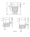
- Fig. 1a and 1b show a schematic plan view of the exemplary embodiments Ia and Ib of the ceramic implant and Fig. 2 shows a schematic longitudinal section through the exemplary embodiment II of the ceramic implant with an axial implant length L, a distal enossal threaded portion A, a gingival intermediate portion B, a proximal portion C and an implant axis 25th
- the enossal threaded portion A of the exemplary ceramic implants Ia, Ib and II is equipped with a thread 1, which optionally has at least one groove 2 and also optionally a threaded outlet 23.
- the groove 2 opens to the distal implant front side.
- the intermediate region B has an extension zone 4 and screw-in geometry 5.
- the proximal region C is equipped with at least one structure for fastening a one-part or multi-part structural element.
- the exemplary ceramic implants Ia, Ib and II differ only in the proximal region C.
- the proximal portion C is formed as a conical post 6a for receiving a structural member.
- the central axis of the post 6a of embodiment Ia coincides with the implant axis 25 in the intermediate region B and the enossal thread region A.
- the proximal portion C is formed as an angled post 6b.
- the post is maximally angled so much that the post does not protrude beyond the inner radius r 2 of the non-rotationally symmetrical outer structure of Einfilgeometrie 5. This is in the Fig. 1b represented by the auxiliary line h.
- this Einfgeometrie for the same insertion tool from the proximal side accessible as for a corresponding embodiment of the ceramic implant with, for example, a conical post whose central axis with the implant axis 25 in the intermediate region B and in the enossal thread region A matches.
- the proximal region is designed as a ball anchor 7 for receiving a structural element and has a head 8 and a constriction 9.
- the threaded portion A of the exemplary ceramic implants Ia, Ib and II has a self-tapping thread 1 with cutting edges 3 of the thread 1 on the groove 2.
- the groove 2 may optionally record when cutting screwed bone material. While the illustrated exemplary groove 2 extends axially, in other embodiments, for example, it may be helical rather than axial.
- d A and d B denote exemplary implant diameters in the threaded area A and in the intermediate area B of the ceramic implant.
- d 5 denotes an exemplary implant diameter of the insertion geometry 5 in the region B.
- r 1 denotes an outer radius and r 2 an inner radius of the non-rotationally symmetrical outer structure of the insertion geometry 5.
- d 8 denotes the diameter of a round head 8 and d 9 a waist, ie the smallest diameter of a constriction 9 of the proximal region C.
- Fig. 2 shows that each implant diameter in the intermediate region B as the exemplified implant diameter d B at least equal to or greater than twice the core radius r K of the thread 1 in the threaded portion A. Since the Eindusgeometrie 5 is arranged in the intermediate region B, and each implant diameter d 5 Einfilgeometrie must 5 may be greater than, or be the same size as twice the core radius of the thread r K in the threaded area A. in some embodiments, the double inner radius r 2 of the non-rotationally symmetrical outer structure of the Eincardgeometrie 5 is at least equal to twice the core radius of the thread r K. In the exemplary embodiments illustrated in FIG Fig. 1 and in Fig.
- a threaded outlet 23 is arranged, in which the core diameter r K increases in the proximal direction while the outer radius r A remains unchanged.
- the exemplary embodiments I and II of the ceramic implant have an embodiment with a tulip-shaped extension zone 4.
- the implant diameter expands starting at the distal end of the extension zone at the border to the threaded portion A in the proximal direction in an exemplary first convex and then concave S-curve.
- Einfilgeometrie 5 is arranged, here by way of example with a slightly reduced implant diameter.
- a shoulder 11 is formed at the proximal end of the extension zone 4, or at the distal end of the insertion geometry 5. This shoulder 11 has an advantageous stopping action on a screwing-in tool which is attached to the insertion geometry 5 from the proximal side.
- the axial total length L of some embodiments of the ceramic implant is, for example, in a range of 10 to 25 mm and in particular in a range with a lower limit of a value between 11 to 18 mm and an upper limit of a value between 19 to 24 mm.
- the lengths mentioned below relate in each case to the axial length of an implant region of some embodiments of the ceramic implant, wherein specific lengths of one implant region can be combined freely with specific lengths of another implant region of the ceramic implant.
- the distal enossal thread area A for anchoring the ceramic implant in the bone for example, has a length in a range of 8 to 16 mm and in particular in an area with a lower limit of 9, 10, 11 or 12 mm and an upper limit of 11, 12, 13, 14 or 15 mm.
- the intermediate region B has, for example, a length in a range of 1 to 4 mm and in particular in an area with a lower limit of 1, 1.5 or 2 mm and an upper limit of 2.5, 3 or 3.5 mm.
- the proximal region A with at least one structure for fastening a one-part or multi-part structural element has for example a length in a range of 1.5 to 6 mm and in particular in a range with a lower limit of 1.5, 2.0, 2.5, or 3.0 mm and an upper limit 2.5, 2.75, 2.9, 3.0, 3.1, 3.25, 3.5, 4, 4.5 or 5 mm.
- Some exemplary embodiments of a ceramic implant system include, for example, ceramic implants having an axial length of the distal endosseous region A of 8 to 16 mm or 9 to 14 mm or 10.5 to 12 mm, in particular 11.25 mm, an axial length of the intermediate region B of 2 to 3 mm, in particular 2.5 mm and an axial length of the proximal region C of 2 to 3.5 mm, in particular 2.5 to 3 mm or 2.7 to 2.8 mm.
- the axial length of Eindeckgeometrie 5 is in some embodiments in the range of 0.5 to 1.5 mm, in particular from 0.8 to 1.2 mm or 0.9 mm to 1.1 mm.
- Some embodiments of the ceramic implant with a lockball male have an axial length of the threaded portion A of between, for example, 7 mm and 13 mm, in particular 8.5 mm, 10 mm and 11.5 mm, of the intermediate range B for gingiva heights of, for example, 2 mm to 5 mm, in particular 2.0 mm, 2.5 mm, 3.0 mm, 3.5 mm, 4.0 mm or 4.5 mm and the proximal region of, for example, 2.9 mm to 3.9 mm, in particular 3.4 mm with a double core radius r K of the thread of, for example, 3.9 to 5 mm, in particular 4.1 to 4.7 mm.
- Embodiments an axial length of Eincardgeometrie of 0.4 to 1.4 mm, in particular 0.7 to 1.1 mm and the extension zone of 1.5 to 2.5 mm, in particular 1.8 to 2.2 mm or other combination, which results in the desired axial length of the intermediate region for a corresponding Gingvia bal.
- Some embodiments of the ceramic implant system include, as an alternative or in addition to the different embodiments of the ceramic implant described above, embodiments in which the thread diameter or the implant diameter differs at the proximal end of the threaded region.
- the implant diameter measures, for example, between 3 and 4.5 mm, or in particular between 3.5 mm and 4 mm.
- Fig. 3 shows exemplary embodiments III and IV of the ceramic implant in partial schematics with the proximal part C and the intermediate region B having a Einwindgeometrie 5, an optional extension zone 4 and an optional spacer zone 24 and with an incomplete illustrated threaded portion A, of which a distal part of the thread and the distal end of the threaded portion A are not drawn.
- the proximal part C of the embodiments III and IV is configured identically and has a ball anchor, for example, a Lockball male part for a commercial matrix.
- the Einfgeometrie (5) adjacent to the distal end of the proximal part of both embodiments III and IV does not have the same rotationally symmetrical outer structure, here for example an equal thickness with the same outer radii r 1 and the same inner radii r 2 .
- the two exemplary embodiments of the ceramic implant III and IV have a different double outer radius r A of the thread 1 and thus a different implant diameter at the proximal end of the thread.
- This difference is, for example, less than 1 mm, in particular 0.1 mm to 0.8 mm or 0.2 to 0.6 mm or 0.3 to 0.5, for example 0.4 mm.
- the outer radii r 1 of Einfilgeometrien 5 of the embodiments shown by way of example III and IV are the same size as the radius r T of the extension zone 4 at its proximal end.
- the inner radii r 2 of the non-rotationally symmetrical outer structure of Einfilgeometrien 5 of the exemplary embodiments III and IV are, for example, 0.025 mm to 0.3 mm smaller than the outer radii r 1 in particular 0.05 mm to 0.15 mm or 0.07 to 0.1 mm smaller than the outer radii r 1 and as the radius r T at the proximal end of the extension zone 4.
- the outer radius r 1 of the outer structure of Eincoolgeometrie measures for example 1.5 mm to 2.5 mm, in particular 1.8 mm to 2.2 mm.
- a diameter d 5 of the Eincardgeometrie measures for example 3.5 to 5 mm, in particular 3.8 mm to 4.7 mm or 4 mm to 4.5 mm.
- the two in Fig. 3 illustrated embodiments of the ceramic implant are included in an exemplary ceramic implant system in which the different configuration of the extension zones 4 is tuned to the different thread diameter, that the extension zone of both embodiments III and IV at its distal end has an implant diameter which is the same size as the respective Implant diameter at the proximal End of the threaded portion or as the double outer radius r A of the thread and that the extension zone has at its proximal end an implant diameter which is equal to the same double outer radius r 1 of the same outer structure of Eincardgeometrie. 5
- Exemplary embodiments III and IV of the exemplary ceramic implant system include, in addition to the extension zone 4 in the intermediate region B, an optional clearance zone 24 disposed between the proximal end of the threaded region A and the distal end of the extension zone 4.
- the implant diameter does not expand in comparison to the implant diameter at the proximal end of the threaded region and, in particular, as in the embodiments III and IV, it is the same size as twice the outer radius r A of the thread.
- Fig. 4 shows schematic partial views of three further exemplary ceramic implants V, which have a locator male in the proximal region.
- Such and optionally further embodiments of the ceramic implant are contained, for example, in a ceramic implant system.
- Some embodiments of the ceramic implant with a locator male have an axial length of the threaded portion A of, for example, 8 to 12 mm, in particular 8.5 mm, 9.0 mm, 9.5 mm or 10.0 mm to 10.5 mm, 11.0 mm or 11.5 mm, an axial length of Intermediate area B for different gingiva heights of, for example, 2 mm to 5 mm, in particular 2.5 mm, 3.0 mm or 3.5 mm to 3.5 mm, 4.0 mm or 4.5 mm and the proximal region of for example 2.5 to 4.5, in particular 3.0 to 4.0 mm.
- the implant diameter of these embodiments in the proximal threaded area measures, for example, between 3 mm and 4.5 mm, in particular from 3.5 mm to 4.0 mm.
- the intermediate region B is in some embodiments, such as ceramic implants V, VI and VII in FIG Fig. 4 designed without expansion zone and without a clearance zone over its entire axial length as non-rotationally symmetrical Einwindgeometrie.
- the axial lengths of Eincoolgeometrien 5 are between 2 and 5 mm, those of the drawn implants V, VI and VII measure, for example, 2.5 mm, 3.5 mm and 4.5 mm.
- the intermediate region is not designed over the entire axial length as Einfilgeometrie and additionally has a clearance zone and or an extension zone.
- the outer radius of Einfilgeometrie 5 is greater than the outer radius of the thread.
- Fig. 5 shows a cross section through the Einfgeometrie 5 in the FIGS. 1 to 4 Exemplary embodiments of the ceramic implant
- This Einfgeometrie 5 is formed as a non-rotationally symmetrical outer structure, for example in the form of a constant thickness 13.
- a constant thickness 13 which is a regular uniform thickness, based on a regular pentagon with an angle ⁇ of 72 °, with a width 14 which is defined to be constant.
- the measure of the constant width 14 is, for example, in one range with a lower limit of 3, 3.25, 3.5, 3.75 4, 4.25, 4.5, 4.75 or 5.0 mm and an upper limit in a range of 4.5, 4.75, 5.0, 5.5, 5.75 or 6 mm and is in particular in the range from 3.5 to 5.5 mm.
- Einwindgeometrie 5 in the intermediate region B is the non-rotationally symmetrical outer structure, for example, an irregular uniform thickness or an outer edge.
- the implant diameter of the insertion geometry measures, for example, 3.5 to 6 mm, in particular 4 to 5 mm.
- FIGS. 1a . 1b . 2 and 3 show that the Einfgeometrie 5 is set back in the exemplary embodiments Ia, Ib and II to IV compared to the distal adjacent extension zone 4, that is, the outer radius r 1 of the non-rotationally symmetrical Eindeckgeometrie is smaller or in particular the same size as the outer radius r T the distally adjacent extension zone 4, and the inner radius r 2 of Einfgeometrie 5 is smaller than the outer radius r T of the distal adjacent extension zone 4.
- the implant diameter d 5 of the recessed insertion geometry 5 is smaller than the implant diameter of the implant region adjoining the insertion geometry 5 distally, such as, for example, a distal one adjacent extension zone 4, a distally adjacent spacer zone 24 or a distally adjacent threaded section A.
- the insertion geometry 5 protrudes from an implant region distally adjacent to the insertion geometry 5, such as against a distally adjacent extension zone 4, a distally adjacent spacer zone 24 or a distally adjacent threaded section A.
- the implant diameter d 5 of Einwindgeometrie 5 larger and in particular the outer radius r 1 of the outer structure of Eincardgeometrie 5 greater than the diameter or the largest radius in a sectional surface perpendicular to the axis through the ceramic implant immediately distal Einfilgeometrie at the proximal end, for example, the optional extension zone 4 or the optional distance zone 24 or threaded portion A.
- Embodiments V, VI and VII of the ceramic implant shown in FIG Fig. 4 have such opposite to the distally adjacent spacing zone projecting Eincardgeometrie 5.
- Fig. 6 shows a cross-section through an exemplary embodiment of a part 15 of a multi-part structural element of a dental implant system.
- the part 15 is a retaining element which can be fastened in the proximal region C of the ceramic implant and which can be connected to at least one further part of the structural element and, for example, holds a dental prosthesis such as a bridge, prosthesis or tooth crown.
- Exemplary holding element 15 is designed as a die and has a hemispherical cavity 16 for receiving the head 8 of the Ball anchor 7, wherein the diameter d 16 of the cavity 16 is adapted to the head diameter d 8 .
- the holding element 15 embodied as a die has a recess 17 for a snap element 18, for example for a snap ring, which is inserted into the depression 17 between the surface of the ceramic implant and the inner wall of the matrix, in particular in the region of the constriction 9 of the ceramic implant.
Abstract
Description
- Die Erfindung liegt auf dem Gebiet der Medizinaltechnik und betrifft ein Zahnimplantat, insbesondere ein einstückiges Keramikimplantat, ein Keramikimplantatsystem sowie ein Zahnimplantatsystem und ein Set mit einem Keramikimplantat.
- Keramikimplantate und insbesondere Keramikimplantate bestehend aus Zirkonoxidbasierter Keramik weisen gegenüber den bekannten Titanimplantaten verschiedene Vorteile auf. Sie sind von hervorragender Biokompatibilität, da Keramik und insbesondere Zirkonoxid basierte Keramik kaum physiologische Reaktionen und insbesondere keine allergische Reaktionen auslöst. Metallfreie Keramikimplantate sind deshalb für Allergiker sehr geeignet. Darüber hinaus bewirkt die optimale Gewebeverträglichkeit von Keramikimplantaten, eine sehr schnelle Zahnfleischanlagerung an frisch implantierte Zahnimplantate. So entsteht auch dank der weissen Farbe der Zirkonoxid-Keramik eine verbesserte Ästhetik gegenüber den traditionellen Titanimplantaten. Das schöne Einwachsen in das Zahnfleisch bleibt auch längerfristig erhalten, da Keramikimplantate weniger Plaque anlagern und deshalb im Vergleich zu Titanimplantaten Zahnfleischentzündungen und Zahnfleischrückzugserkrankungen seltener sind:
- Keramikimplantate haben gegenüber Titanimplantaten jedoch den Nachteil, dass Keramikmaterial, insbesondere Oxidkeramik wie Zirkonoxid-basierte Keramik oder Aluminiumoxid-basierte Keramik ein sprödhartes Material ist. Eine Herausforderung bleibt deshalb die vergleichsweise hohe Bruchanfälligkeit des Keramikmaterials zu überwinden, selbst wenn beispielsweise Yttrium-stabilisierte Zirkonoxid-basierte Keramik bereits eine verbesserte Bruchstabilität besitzt. Die technische Ausgestaltung von Keramikimplantaten muss also auf die sprödharten Materialeigenschaften abgestimmt werden. Ein einteiliges Implantatsystem ist weniger bruchanfällig als ein zweiteiliges Implantatsystem.
- Viele Zahnimplantate, Keramikimplantate und andere Implantate, werden in den Kieferknochen geschraubt. Alle in den Knochen geschraubten Implantate, ob einteilig oder zweiteilig, werden in den Knochen geschraubt, indem ein Eindrehwerkzeug an eine Eindrehgeometrie des Implantates angesetzt wird und ein Eindrehmoment auf das Implantat übertragen wird. Falls diese Krafteinwirkung die vergleichsweise geringe Bruchstabilität des Keramikimplantates überdehnt, wird das Implantat beschädigt. Insbesondere bei einer Innenverbindung in Keramik besteht die Gefahr von Brüchen bei Eindrehkräften, welche im oberen Bereich eines üblicherweise angesetzten Drehmomentes von ca. 35 bis 70 Ncm liegen. Implantatbrüche, bei welchen sich auch Keramikstücke vom Implantat lösen können erhöhen das zahnchirurgische Komplikationsrisiko und den Verschleiss von Keramikimplantaten.
- Es ist eine Aufgabe der vorliegenden Erfindung, diese Nachteile im Stand der Technik zu überwinden und ein Keramikimplantat bereitzustellen, welches eine verbesserte Bruchstabilität aufweist selbst und auf welches deshalb eine grösseres Eindrehmoment angesetzt werden kann.
- Diese Aufgabe wird gelöst mit einem einstückigen keramischen Zahnimplantat mit einem distalen enossalen Gewindebereich, einem gingvialen Zwischenbereich und einem proximalen Bereich. Im Gewindebereich ist ein Gewinde angeordnet mit einem Kernradius und einem Aussenradius des Gewindes. Im Zwischenbereich ist eine proximal zugängliche Eindrehgeometrie zum Eindrehen des Gewindebereichs in ein Knochengewebe angeordnet, wobei die Eindrehgeometrie als nicht rotationssymmetrische Aussenstruktur ausgebildet ist. Der proximale Bereich enthält mindestens eine Struktur zur Befestigung eines ein- oder mehrteiligen Aufbauelementes. Im Zwischenbereich ist ein Implantatdurchmesser in jeder Schnittfläche senkrecht zur Implantatachse mindestens gleich gross, wie der doppelte Kernradius des Gewindes. Somit ist auch jeder Implantatdurchmesser durch die Eindrehgeometrie mindestens gleich gross wie der doppelte Kernradius des Gewindes.
- Im vorliegenden Text wird mit Keramikimplantat ein einstückiges keramisches Zahnimplantat bezeichnet, welches aus Keramikmaterial besteht, insbesondere aus Oxidkeramik wie Zirkonoxid-basierte Keramik, insbesondere Yttrium-stabilisieirte Zirkonoxid-basierte Keramik oder Aluminiumoxid-basierte Keramik.
- Die axiale Positionierung eines Bereiches oder einer Struktur wird in dieser Anmeldung mit den Begriffen distal und proximal bezogen auf die Implantationsrichtung so charakterisiert, dass die distale Richtung der Richtung zum apikalen Ende des Zahnimplantates (oder eines Zahns) entspricht und die proximale Richtung der koronalen Richtung des Zahnimplantates (oder eines Zahns) entspricht.
- Der proximale Bereich des Keramikimplantates dient wie ein Abutment eines zweistückigen Implantates insbesondere der Aufnahme und Befestigung eines einteiligen oder mehrteiligen Aufbauelementes. Der proximale Bereich weist deshalb mindestens eine Struktur auf, an und/oder mittels welcher ein Aufbauelement am Keramikimplantat befestigt wird. Beispielhafte Strukturen sind ein konischer oder zylindrischer Pfosten oder ein Kugelanker.
- Der Zwischenbereich des Keramikimplantates enthält die Eindrehgeometrie, welche am proximalen Ende des Zwischenbereichs angeordnet ist. Das proximale Ende des Zwischenbereichs, bzw. das distale Ende des proximalen Bereichs entspricht anatomisch im Wesentlichen dem Zahnfleisch-Durchtrittsbereich. Der Zwischenbereich des Keramikimplantats, welcher in manchen Ausführungsformen distal zur Eindrehgeometrie eine Erweiterungszone und/oder eine Abstandszone enthält, ist im Wesentlichen über seine ganze axiale Länge von Zahnfleisch (Gingvia) umgeben. Das Keramikimplantat eignet sich je nach axialer Länge des Zwischenbereichs für verschiedene Gingviahöhen. Die axiale Länge des Zwischenbereichs hat beispielsweise ein Mass zwischen 1.5 und 5.5 mm, zum Beispiel 2.5mm, 3.5 mm oder 4.5 mm.
- Der ennossale Gewindebereich des Keramikimplantates ist distal zum Zwischenbereich angeordnet und dient der Verankerung des Keramikimplantates im Knochen. Das proximale Ende des Gewindes oder in manchen Ausführungsformen des proximale Ende des Gewindeauslaufs definiert das proximale Ende des Gewindebereichs und gleichzeitig auch das distale Ende des Zwischenbereich.
- Als Implantatradius wird im vorliegenden Text der Abstand zwischen der Implantatachse und der Implantatsoberfläche senkrecht zur Achse bezeichnet. In Bereichen des Implantates mit einem nicht kreisförmigen Querschnitt, insbesondere betreffend die nicht rotationssymmetrische Eindrehgeometrie ist der kleinste Implantatradius definiert als Innenradius und er entspricht dem kleinsten Abstand zwischen der Implantatachse und der Implantatsoberfläche senkrecht zur Achse; und analog ist der grösste Implantatradius definiert als der Aussenradius und er entspricht dem grössten Abstand zwischen der Implantatachse und der Implantatsoberfläche senkrecht zur Achse. Der kleinste Durchmesser einer Schnittfläche senkrecht zur Implantatachse des Implantates ist definiert als die kürzeste Verbindungsstrecke zwischen zwei Punkten auf der Implantatsoberfläche, welche durch die Implantatachse führt. Bei einem regelmässigen geradzahligen Aussenkant, z.B. Aussen-Sechskant, entspricht der kleinste Implantatdurchmesser dem doppelten Innenradius.
- Allgemein, wenn nichts anderes vermerkt wird, ist der Implantatdurchmesser im vorliegenden Text definiert als der mittlere Durchmesser einer Schnittfläche senkrecht zur Achse. Der Implantatdurchmesser ist im Falle einer kreisförmigen Schnittfläche der Kreisdurchmesser. Im Falle einer nicht kreisförmigen Schnittfläche senkrecht zur Implantatsachse, d.h. beispielsweise eine Schnittfläche durch die Eindrehgeometrie im Zwischenbereich des Implantates, ist der Implantatdurchmesser der Kreisdurchmesser jenes Kreises mit Mittelpunkt auf der Implantatachse, welcher eine gleich grosse Fläche wie die nicht kreisförmige Schnittfläche durch das Implantat aufweist. Der kleinste oder grösste Implantatdurchmesser in einem axialen Bereich des Implantates, beispielsweise im Zwischenbereich, im Bereich der Eindrehgeometrie oder im Gewindebereich ist also der kleinste oder grösste Wert des mittleren Durchmessers aller Schnittflächen senkrecht zur Implantatachse in diesem Bereich. Der Implantatdurchmesser des Keramikimplantates am proximalen Ende des Gewindes hat beispielsweise eine Länge von 3 mm bis 4.5 mm, insbesondere 3.5 mm bis 4.0 mm.
- Der Kernradius des Gewindes ist im vorliegenden Text definiert als der Innenradius des Gewindes am proximalen Ende des Gewindes. Der Kerndurchmesser ist definiert als der doppelte Kernradius am proximalen Ende des Gewindes. In manchen Ausführungsformen ist proximal zum proximalen Ende des Gewindes ein Gewindeauslauf angeordnet. In manchen Ausführungsformen des Gewindeauslaufs vergrössert sich der Kernradius in proximaler Richtung, während der Aussenradius des Gewindes unverändert bleibt. Der Aussenradius des Gewindes und des Gewindeauslaufs ist der grösste Radius des Gewindes am proximalen Ende des Gewindes.
- Die Grösse des kleinsten Implantatdurchmessers des Implantates ist ein Faktor, welcher die Bruchfestigkeit des Keramikimplantates wesentlich mitbestimmt. Im Allgemeinen gilt, je grösser der kleinste Implantatdurchmesser des Implantates und insbesondere der kleinste Implantatdurchmesser im Bereich der Eindrehgeometrie ist, umso weniger bruchanfällig ist das Keramikimplantat. Es ist ein grosser Vorteil der Keramikimplantate gemäss der vorliegenden Erfindung, dass der kleinste Durchmesser der Eindrehgeometrie nicht kleiner ist als der Kerndurchmesser des Gewindes und somit die Bruchfestigkeit des erfindungsgemässen Keramikimplantates im Vergleich zu bekannten Keramikimplantaten erhöht wird.
- Der Innenradius der nicht rotationssymmetrischen Aussenstruktur der Eindrehgeometrie bezeichnet den kleinsten Abstand zwischen der Implantatachse und der Implantatsoberfläche senkrecht zur Achse. Der Aussenradius der nicht rotationssymmetrischen Aussenstruktur der Eindrehgeometrie bezeichnet den grössten Abstand zwischen der Implantatachse und der Implantatsoberfläche senkrecht zur Achse. In manchen Ausführungsformen des Keramikimplantats weist die nicht rotationssymmetrische Aussenstruktur der Eindrehgeometrie einen Innenradius auf, welcher gleich gross oder grösser ist wie der Kernradius des Gewindes.
- In manchen Ausführungsformen des Keramikimplantats ist der Unterschied zwischen dem Aussenradius und dem Innenradius der Aussenstruktur der Eindrehgeometrie klein, insbesondere kleiner als 0.3 mm oder 0.2 mm, und beispielsweise ein Mass in einem Bereich zwischen 0.1 mm oder 0.15 mm als Untergrenze und 0.16 mm oder 1.8 mm als Obergrenze aufweist und insbesondere zwischen 0.13 mm und 0.18, beispielsweise 0.15 mm misst. Eine nahezu runde Form der nicht rotationssymmetrischen Aussenstruktur und insbesondere konvexe Aussenstruktur der Eindrehgeometrie liegen einer anatomischen Form sehr nahe.
- In manchen Ausführungsformen des Keramikimplantats ist der Aussenradius der Eindrehgeometrie mindestens gleich gross ist wie der Ausserradius des Gewindes.
- In manchen Ausführungsformen enthält weist der Zwischenbereich des Keramikimplantates zusätzlich zur Eindrehgeometrie eine Erweiterungszone und/oder eine Abstandszone auf. Die Erweiterungszone ist distal zur Eindrehgeometrie und proximal zum Gewindebereich angeordnet und grenzt in manchen Ausführungsformen direkt an das proximale Ende des Gewindebereichs, insbesondere unmittelbar an das Gewinde oder den Gewindeauslauf. Der Implantatdurchmesser ist am distalen Ende der Erweiterungszone in manchen Ausführungsformen gleich gross wie und in ändern Ausführungsformen grösser als der doppelte Aussenradius des Gewindes und er erweitert sich in der Erweiterungszone in proximaler Richtung. Am proximalen Ende der Erweiterungszone ist der Implantatdurchmesser grösser als an ihrem distalen Ende. Die Erweiterungszone ist in manchen Ausführungsformen als tulpenförmige Erweiterung ausgebildet. welche in einer S-Kurve auskragt.
- Die Erweiterungszone ist geeignet, den Implantatdurchmesser im Zwischenbereich in proximaler Richtung zu vergrössern. Bei manchen Ausführungsformen von Implantaten beispielsweise mit einem vergleichsweise kleinen Implantatdurchmesser im Gewindebereich nimmt der Implantatdurchmesser in der Erweiterungszone in proximaler Richtung zu. Auf diese Weise können Sets von Keramikimplantaten mit unterschiedlichem Gewindedurchmesser bereitgestellt werden, deren Eindrehgeometrien nicht rotationssymmetrischen Aussenstrukturen mit identischen Massen aufweisen wie beispielsweise gleiche Innen- und Aussenradien eines Gleichdick.
- In manchen Ausführungsformen ist die Erweiterungszone des Zwischenbereichs zum Gewinde beabstandet, das heisst der Implantatsdurchmesser erweitert sich nicht unmittelbar proximal angrenzend zum Gewinde, sondern der Zwischenbereich weist eine Abstandszone auf. Die Abstandszone ist in Ausführungsformen mit einer Erweiterungszone zwischen dem proximalen Ende des Gewindebereichs und dem distalen Ende der Erweiterungszone oder in Ausführungsformen ohne Erweiterungszone zwischen dem proximalen Ende des Gewindebereichs und dem distalen Ende der Eindrehgeometrie angeordnet. In der Abstandszone ist der Implantatradius mindestens gleich gross oder grösser als der Kernradius des Gewindes und im Wesentlichen gleich gross wie der Aussenradius des Gewindes oder Gewindeauslaufs, insbesondere ist der Implantatradius gleich gross wie der Aussenradius des Gewindes oder Gewindeauslaufs.
- In manchen Ausführungsformen des Keramikimplantats mit Erweiterungszone ist der Aussenradius der Eindrehgeometrie höchstens gleich gross wie ein Ausserradius der insbesondere tulpenförmigen Erweiterungszone an deren proximalen Ende.
- In manchen Ausführungsformen ist der Implantatdurchmesser der Eindrehgeometrie etwas kleiner als der Implantatdurchmesser am proximalen Ende der Erweiterungszone, beispielsweise weniger als 0.3 mm oder 0.2 mm kleiner und insbesondere zwischen 0.13 mm und 0.18 mm kleiner, jedoch ist der Implantatdurchmesser im ganzen Zwischenbereich, also auch jeder Implantatdurchmesser durch die Eindrehgeometrie gleich gross oder grösser wie der Kerndurchmesser des Gewindes.
- In manchen Ausführungsformen misst der Implantatdurchmesser am proximalen Ende der Erweiterungszone mindestens 125%, insbesondere mindestens 150%, 175%, 200% oder 225% des Implantatdurchmessers am proximalen Ende des Gewindebereichs Im Gegensatz zu den vorliegend beschriebenen Keramikimplantaten, ist bei Keramikimplantaten, welche aus dem Stand der Technik bekannt sind, die Eindrehgeometrie im proximalen Bereich angeordnet und nicht im Zwischenbereich. Deshalb weisen diese bekannten Keramikimplantate einen vergleichsweise kleineren Implantatsdurchmesser im Bereich der Eindrehgeometrie sowie eine höhere Bruchanfälligkeit auf.
- Ein grosser Vorteil der Anordnung der proximal zugänglichen Eindrehgeometrie im Zwischenbereich, in welchem jeder Implantatdurchmesser mindestens gleich gross ist wie der Kerndurchmesser im Gewindebereich, ist der vergrösserte Abstand der Eindrehgeometrie zur Implantatachse. Eine bestimmte Kraft, welche auf die Eindrehgeometrie eines erfindungsgemässen Keramikimplantat angesetzt wird, bewirkt ein grösseres Drehmoment, als eine gleich grosse Kraft, welche auf ein herkömmliches Implantat, dessen Eindrehgeometrie einen kleineren Abstand zur Implantatachse aufweist, bewirken würde. Durch die Vergrösserung des Abstandes der Eindrehgeometrie zur Implantatachse bewirkt eine vergleichsweise kleinere Kraft ein ausreichend grosses Drehmoment, um das Implantat in den Knochen einzudrehen, und belastet das sprödharte Keramikmaterial des Implantates weniger. Dies senkt die Bruchanfälligkeit des erfindungsgemässen Keramikimplantates.
- Die Erniedrigung des Bruchrisikos durch die erfindungsgemässe Anordnung der Eindrehgeometrie im Zwischenbereich mit einer Dimensionierung des Implantatdurchmessers, so dass er mindestens gleich gross ist wie der grösste Gewindedurchmesser, erweist sich deshalb als besonders vorteilhaft bei Keramikimplantaten mit einem selbst-schneidenden Gewinde. Denn auf die Eindrehgeometrie eines Implantats mit selbst-schneidendem Gewinde muss eine erhöhte Kraft angesetzt werden, um das Implantat in das Knochengewebe einzudrehen im Vergleich zum Eindrehen eines Implantats in eine Gewindebohrung, welche in das Knochengewebe vorgebohrt wurde. Deshalb sind insbesondere herkömmliche Keramikimplantate mit selbst-schneidendem Gewinde bruchanfällig.
- Ein weiterer grosser Vorteil der Anordnung der Eindrehgeometrie im Zwischenbereich ist dass diese nicht versehrt wird, wenn das Implantat im proximalen Bereich beschliffen wird oder bricht und deshalb immer noch vorhanden ist, um das Implantat aus dem Knochen herauszudrehen, falls es entfernt werden muss.
- Ein weiterer Vorteil der Anordnung der Eindrehgeometrie näher zum proximalen Ende des Gewindebereichs entsteht durch eine sehr feine aber sichtbare Linie auf der Implantatsoberfläche an der Grenze zwischen dem Gewinde und der Eindrehgeometrie bzw. zur Erweiterungszone oder Abstandszone. Dies stellt für den Zahnarzt eine Implantationshilfe dar. Dies trifft selbst bei einer sehr anatomischen Ausbildung der nicht rotationssymmetrischen Aussenstruktur zu, welche beispielsweise als nahezu rundes konkaves Fünf-Gleichdick ausgebildet ist, und welche beispielsweise nur im Bereich von weniger als 3 mm, insbesondere weniger als 2 mm zurückversetzt ist oder hervorspringt.
- Ein weiterer Vorteil der Anordnung der proximal zugänglichen Eindrehgeometrie im Zwischenbereich, ist die Verschiebung der Eindrehgeometrie in distale Richtung, so dass zusätzliche Freiheitsgrade für die technische Ausgestaltung, wie die Gestaltung der Form und Oberfläche, des proximalen Bereichs und somit für die Gestaltung der mindestens einen Struktur zur Befestigung eines Aufbauelementes gewonnen werden. Beispielsweise kann die axiale Länge des proximalen Bereichs vergleichsweise kürzer sein als in Keramikimplantaten aus dem Stand der Technik, da die Eindrehgeometrie nicht auch in diesem proximalen Bereich angeordnet ist. Die Wahl der Form und die technische Ausgestaltung des proximalen Bereichs ist im Wesentlichen unabhängig von der weiter distal angeordneten Eindrehgeometrie. Dies vergrössert die Anpassungsmöglichkeiten des proximalen Bereichs an Parameter, welche das Aufbauelement erfordert.
- Ein weiterer Vorteil der Anordnung der Eindrehgeometrie im Zwischenbereich ist die Möglichkeit eine einzige Eindrehgeometrie mit gleich bleibender Form und Grösse für eine Anzahl von verschiedenen Keramikimplantaten als Keramikimplantatsystem bereitzustellen. Durch die Anordnung der Eindrehgeometrie im Zwischenbereich ist ihre Ausgestaltung und ihr Implantatdurchmesser unabhängig wählbar von der Ausgestaltung des proximalen Bereichs und dessen mindestens einen Struktur zur Befestigung des Aufbauelementes und auch unabhängig vom Implantatdurchmesser im distalen enossalen Bereich.
- Ein weiterer Aspekt der Erfindung betrifft also ein Keramikimplantatsystem mit mindestens zwei Keramikimplantaten, wobei diese Keramikimplantate mit einer gleichen nicht rotationssymmetrischen Aussengeometrie der Eindrehgeometrie ausgerüstet sind. Eine gleiche nicht rotationssymmetrische Aussenstruktur bedeutet, dass die Aussenstruktur funktionell gleich ist, das heisst, dass sie mit einem strukturell identischen Eindrehwerkzeug funktionell so zusammenwirkt, dass mittels Ansetzen des Werkzeug ein Drehmoment auf das Keramikimplantat übertragen werden kann und es beispielsweise in den Knochen eindrehbar ist. In manchen Ausführungsformen der gleichen nicht rotationssymmetrischen Aussengeometrie sind die Schnittflächen der Eindrehgeometrie senkrecht zur Implantatachse deckungsgleich. Manche Ausführungsformen des Keramikimplantatsystems enthalten zusätzlich ein Eindrehwerkzeug, welches mit der funktionell gleichen Aussenstruktur der Eindrehgeometrie zusammenwirkt.
- So weisen manche Ausführungsfonnen des Keramikimplantatsystems mindestens zwei Keramikimplantate mit einer gleichen, im Sinne von funktionell gleichen Eindrehgeometrie auf oder insbesondere mit einer identischen Form und Grösse der Eindrehgeometrie auf, bei welchen sich beispielsweise der proximale Bereich dieser Keramikimplantate unterscheidet beispielsweise in Bezug auf die axiale Länge oder Implantatdurchmesser oder indem der proximale Bereich mit Patrizen für verschiedene Matrizensysteme ausgerüstet ist. In weiteren Ausführungsformen des Keramikimplantatsystems unterscheiden sich die Keramikimplantate alternativ oder zusätzlich im Gewindebereich und weisen beispielsweise unterschiedliche axiale Längen oder Implantatdurchmesser des Gewindebereichs auf, insbesondere einen unterschiedlichen Aussendurchmesser des Gewindes an dessen proximalen Ende. In manchen Ausführungsformen weist die Eindrehgeometrie mit einer gleichen Aussengeometrie, im Sinne der oben beschriebenen funktionell gleichen Aussengeometrie, eine unterschiedliche axiale Länge auf. So unterscheiden sich die Keramikimplantate eines Keramikimplantatsystems alternativ oder zusätzlich zu Unterschieden im proximalen und / oder im Gewindebereich also auch im Zwischenbereich, wie oben genannt beispielsweise in der axialen Länge der Eindrehgeometrie oder beispielsweise zusätzlich oder alternativ auch im Vorhandensein oder der Ausgestaltung der optionalen Erweiterungszone und/oder Abstandszone.
- Vorteilhafterweise muss für ein Keramikimplantatsystem enthaltend eine Mehrzahl von Keramikimplantaten nur ein einziges Eindrehwerkzeug bereitgestellt werden, welches mit einer solchen funktionell gleichen Eindrehgeometrie insbesondere von identischer Form und Grösse für verschiedene Ausführungsformen des Keramikimplantates bzw. für ein ganzes Keramikimplantatsystem mit einer Mehrzahl von Keramikimplantaten funktionell zusammenwirkt.
- Die im Zwischenbereich angeordnete Eindrehgeometrie einteiliger Keramikimplantate ist typischerweise eine Aussenstruktur. Gängige Eindrehgeometrien sind Aussenpolygonprofile, insbesondere ein Aussen-Sechskant oder ein Aussen-Achtkant oder ein Aussen-Zwölfkant. Beim Eindrehen eines Implantates in den Knochen mittels einer Aussengeometrie entstehen im Gegensatz zum Eindrehen mittels Innengeometrie keine Zugkräfte im Implantat. Solche Zugkräfte im Implantat entstehen typischerweise durch das Aufdrücken eines Eindrehinstrumentes in eine Innengeometrie und das sprödharte Keramikmaterial ist auf solche Zugkräfte sehr empfindlich.
- Manche Ausführungsformen weisen als Eindrehgeometrien eine konvexe oder konkave mehrlappige (multi-lobe) Aussenstruktur auf, wie beispielsweise ein regelmässiges oder unregelmässiges Gleichdick. Ein Gleichdick (engl. curve of equal width) ist eine geschlossene Kurve konstanter Breite. Dabei ist die Breite definiert als Abstand zwischen zwei parallelen Geraden, welche die geschlossene Kurve auf gegenüberliegenden Seiten berühren. Die triviale Form des Gleichdick, nämlich die Kreisform ist ausgeschlossen, da sie keine Übertragung von Drehmomenten zulässt. Bevorzugt sind Gleichdick-Aussenstrukturen regelmässiger Gleichdick, welche bezüglich einer axialen Drehung um einen Symmetriewinkel symmetrisch sind. Regelmässige Gleichdick beruhen auf regelmässigen Polygonen mit einer ungeraden Anzahl von Ecken. Ein weiterer Vorteil Eindrehgeometrien in der Form eines Gleichdick ist ihre Herstellbarkeit durch abtragende Verfahren.
- Die Eindrehgeometrie kann zylindrisch sein, d.h. entlang der Achse translationssymmetrisch oder konisch, d.h. sich in einem Bereich unter Beibehaltung der Form der Umfangslinie in Funktion der axialen Position stetig verkleinernd oder vergrössernd oder sie kann auch beispielsweise in einem Schnitt parallel zur Achse eine leicht konvexe oder leicht konkave Form aufweisen.
- Der kleinste Implantatdurchmesser der Eindrehgeometrie des Keramikimplantates ist jedoch in allen Ausführungsformen mindestens gleich gross wie der Kerndurchmesser des Gewindes. In manchen Ausführungsformen des Keramikimplantates ist der Implantatdurchmesser der Eindrehgeometrie mindestens 10%, 15%, 25% oder 35% grösser als der Kerndurchmesser, insbesondere ist er mindestens 12%, 14%, 16%, 18%, 20%, 22%, 24%, 26%, 28%, 30% oder 32% grösser bezogen auf den Gewindedurchmesser. Die Spannungsverteilung im Keramikimplantat ist bei einer als Aussenstruktur ausgebildeten Eindrehgeometrie mit vergleichsweise grossem Implantatsdurchmesser günstiger als bei Innengeometrien, welche mit dünnen Wandstärken des Keramikimplantates einhergehen und deshalb ein Bruchrisiko begünstigen.
- Der proximale Bereich ist proximal zum Zwischenbereich und somit auch proximal zur Eindrehgeometrie angeordnet. In manchen Ausführungsformen ist der grösste Implantatdurchmesser im proximalen Bereich höchstens gleich gross oder kleiner als der grösste Implantatdurchmesser der Eindrehgeometrie. In manchen Ausführungsformen der grösste Implantatdurchmesser im proximalen Bereich höchstens gleichgross wie der grösste Implantatdurchmesser Gewindebereich und insbesondere höchstens gleichgross ist wie der grösste Gewindedurchmesser.
- Insbesondere weisen manche Ausführungsformen des Keramikimplantats im proximalen Bereich in jeder Schnittfläche senkrecht zur Implantatachse einen
- Implantatdurchmesser auf, welcher kleiner ist als der doppelte Innenradius der Eindrehgeometrie. Der grösste Implantatdurchmesser solcher Ausführungsformen des Keramikimplantates ist dann im Zwischenbereich angeordnet.
- In manchen Ausführungsformen des Keramikimplantates weist der proximale Bereich eine zylindrische insbesondere eine kreiszylindrische Form auf. In weiteren Ausführungsformen des Keramikimplantates nimmt der Implantatdurchmesser ab der Grenze zum Zwischenbereich in proximaler Richtung kontinuierlich ab. In weiteren Ausführungsformen des Keramikimplantates wechseln sich Zu- und Abnahme des Implantatdurchmesser ab, beispielsweise so, dass der Implantatdurchmesser ab der Grenze zum Zwischenbereich in proximaler Richtung zuerst abnimmt und sich dann wieder erweitert und/oder er bildet beispielsweise in proximaler Richtung zuerst eine Einschnürung und dann ein Köpfchen. Eine derartige Form mit einem Köpfchen im proximalen Bereichs ist besonders geeignet für ein Keramikimplantat mit einem Kugelanker (engl. Lockball) für das Aufbauelement.
- In manchen Ausführungsfonnen ist die mindestens eine Struktur zur Befestigung eines ein- oder mehrteiligen Aufbauelementes als Patrize ausgebildet, welche mit einem als Matrize ausgebildeten Aufbauelement verbindbar ist. In manchen Ausführungsformen enthält die mindestens eine Struktur zur Verbindung eines Aufbauelementes eine Patrize, welche mit einem als Matrize ausgebildeten Aufbauelement verbindbar ist. Solche Matrizen und insbesondere auch Matrizensysteme, sind im Stand der Technik bekannt als Verbindungselemente zur Fixierung von einem gegebenenfalls abnehmbarem Zahnersatz auf einer mit der Matrize verbindbaren Patrize. In solchen Ausführungsformen des erfindungsgemässen einteiligen Keramikimplantates ist also die Patrize ein proximaler Bestandteil des Keramikimplantates während bei bekannten zweiteiligen Implantaten üblicherweise eine Patrize in das im Knochen verankerte Implantat eingeschraubt wird. Insbesondere weist in manchen Ausführungsformen des Keramikimplantates der proximale Bereich eine Patrize auf, welche kompatibel ist mit einem handelsüblichen Patrizen-Matrizensystem wie beispielsweise eine Locator Patrize für ein Locator Matrizensystem, beispielsweise das Novaloc™ Matrizensystem oder eine Lockball Patrize für ein Lockball Matrizensystem, beispielsweise das Pro-Snap Matrizensystem von Cendres Metaux.
- Vorteilhafterweise kann auf Ausführungsformen des Keramikimplantates mit einem Kugelanker ein Aufbauelement in jeder beliebigen Drehposition aufgesetzt werden. So kann der Zahnchirurg den Gewindebereichs ohne Rücksicht auf die Drehposition so weit eindrehen bis die axiale Höhe des implantierten Implantates optimal eingestellt ist. Ein Keramikimplantat ausgerüstet mit einem Kugelanker im proximalen Bereich stellt deshalb vergleichsweise weniger hohe Anforderungen an die Implantationsgenauigkeit.
- In manchen Ausführungsformen des Keramikimplantates steht der proximale Bereich, bzw. die Implantatachse im proximalen Bereich in einem Winkel von bis zu 25° relativ zur distal angrenzenden Eindrehgeometrie, bzw. zur Implantatachse durch die Eindrehgeometrie. In manchen Ausführungsformen des Keramikimplantates ist beispielsweise ein proximaler Teil als abgewinkelter Pfosten ausgebildet.
- Manche Ausführungsformen des Keramikimplantats weisen im proximalen Bereich Strukturen auf wie beispielsweise eine Rippung oder dergleichen zur zusätzlichen Befestigung oder Verdrehsicherung eines der Teile des ein- oder mehrteiligen Aufbauelementes oder Rillen und dergleichen beispielsweise zur Aufnahme einer eines Schnappelementes, beispielsweise eines Schnapprings oder einer Dichtung. Ein weiterer Aspekt der Erfindung betrifft ein Zahnimplantatsystem aufweisend ein Keramikimplantat und zusätzlich aufweisend ein einteiliges Aufbauelement oder mindestens einen Teil eines mehrteiligen Aufbauelementes, insbesondere ein Halteelement. Das Halteelement ist in manchen Ausführungsformen eine Matrize, welche an der oder mittels der mindestens einen Struktur im proximalen Bereich am Implantat befestigbar ist.
- Ein mehrteiliges Aufbauelement enthält oder besteht aus beispielsweise einem Halteelement, insbesondere aus einer Matrize, und einem Zahnersatz wie eine Krone oder eine Zahnprothese. In manchen Ausführungsformen des Zahnimplantatsystems enthält es beispielsweise das Keramikimplantat und mindestens eine ein- oder mehrteilige Matrize.
- In manchen Ausführungsformen eines solchen mehrteiligen Aufbauelementes ist das Halteelement permanent oder lösbar mit dem proximalen Bereich des Keramikimplantates verbindbar und / oder das Haltelement ist permanent oder lösbar mit dem Zahnersatz verbindbar. In manchen Ausführungsformen des Halteelementes ist es mehrteilig, in andern Ausführungsformen ist es einteilig. In manchen Ausführungsformen ist das Halteelement als ein- oder mehrteilige Matrize für einen Kugelanker ausgebildet.
- Ein weiterer Gegenstand der Erfindung ist ein Set mit mindestens einem Keramikimplantat und einem Eindrehwerkzeug. Optional enthält das Set mehr als ein Keramikimplantat, insbesondere ein Keramikimplantatsystem. Das Eindrehwerkzeug wirkt zusammen mit der Eindrehgeometrie des mindestens einen Keramikimplantates. Das Set enthält optional zusätzlich ein ein- oder mehrteiliges Aufbauelement wie beispielsweise Halteelemente, andere Prothetikteile, oder Trägerelemente für einen Zahnersatz wie Prothesen, Brücken, Kronen und dergleichen. Das Set enthält mindestens ein Aufbauelement oder mindestens einen Teil des Aufbauelementes welches oder welcher für die unmittelbare Befestigung am Keramikimplantat vorgesehen ist.
- Das Keramikimplantat, das Keramikimplantatsystem oder das Zahnimplantatsystem und das Set können in einer sterilen Verpackung vorliegen.
- Nachfolgend werden Ausführungsbeispiele der Erfindung anhand von Figuren ausführlicher beschrieben. Die Erfindung ist nicht auf die in den Figuren dargestellte Kombination von Merkmalen der Erfindung limitiert. Insbesondere ist es auch möglich Merkmale, welche für einen ersten der drei Bereiche, Gewindebereich, Zwischenbereich, proximaler Bereich des Keramikimplantates, spezifisch offenbart sind, mit allen offenbarten Ausführungsformen der beiden andern Bereiche zu kombinieren und nicht nur mit jener oder jenen Ausführungsformen der andern Bereiche, welche beispielhaft in Kombination mit dem ersten Bereich beschrieben sind oder in den Figuren dargestellt sind. Die Figuren sind nicht zwingend massstäblich. Gleiche Bezugszeichen bezeichnen gleiche oder analoge Elemente.
- Auflistung der Figuren:
- Fig. 1a und b
- zeigen beispielhafte Ausführungsformen Ia und Ib eines Keramikimplantats mit einer Erweiterungszone in einer schematischen Aufsicht.
- Fig. 2
- zeigt einen Längsschnitt durch ein beispielhaftes Keramikimplantat II.
- Fig. 3
- zeigt eine schematische Teilaufsicht auf ein Ausführungsbeispiel eines Keramikimplantatsystems enthaltend beispielhafte Keramikimplantate III und IV mit einer gleichen nicht rotationssymmetrischen Aussengeometrie der Eindrehgeometrie und unterschiedlichem Aussenradius des Gewindes.
- Fig. 4
- zeigt eine schematische Teilaufsicht auf eine Ausführungsform des Keramikimplantatsystems mit drei Ausführungsformen V, VI und VII des Keramikimplantats mit gleicher nicht rotationssymmetrischer Aussenstruktur einer Eindrehgeometrie mit unterschiedlicher axialer Länge.
- Fig. 5
- zeigt einen Querschnitt durch eine beispielhafte Ausführungsform der Eindrehgeometrie
- Fig. 6
- zeigt eine beispielhafte Ausführungsform eines Aufbauelementes für ein Keramikimplantat mit einem Kugelanker
-
Fig. 1a und1b zeigen eine schematische Aufsicht auf die beispielhaften Ausführungsformen Ia und Ib des Keramikimplantates undFig. 2 zeigt einen schematischen Längsschnitt durch die beispielhafte Ausführungsform II des Keramikimplantates mit einer axialen Implantatlänge L, einem distalen enossalen Gewindebereich A, einem gingvialen Zwischenbereich B, einem proximalen Bereich C und einer Implantatachse 25. - Der enossale Gewindebereich A der beispielhaften Keramikimplantate Ia, Ib und II ist mit einem Gewinde 1 ausgerüstet, welches optional mindestens eine Nut 2 und ebenfalls optional einen Gewindeauslauf 23 aufweist. Die Nut 2 öffnet sich zur distalen Implantatstirnseite. Der Zwischenbereich B weist in dieser beispielhaften Ausführungsform eine Erweiterungszone 4 und Eindrehgeometrie 5 auf.
- Der proximale Bereich C ist mit mindestens einer Struktur zur Befestigung eines ein- oder mehrteiligen Aufbauelementes ausgerüstet. Die beispielhaften Keramikimplantate Ia, Ib und II unterscheiden sich nur im proximalen Bereich C.
- In der beispielhaften Ausführungsform Ia dargestellt in
Fig. 1a ist der proximale Bereich C als ein konischer Pfosten 6a zur Aufnahme eines Aufbauelementes ausgebildet. Die Mittelachse des Pfostens 6a der Ausführungsform Ia stimmt mit der Implantatachse 25 in dem Zwischenbereich B und dem enossalen Gewindebereich A überein. - In der beispielhaften Ausführungsform Ib dargestellt in
Fig. 1b ist der proximale Bereich C als ein abgewinkelter Pfosten 6b ausgebildet. In manchen Ausführungsformen ist der Pfosten maximal so stark abgewinkelt, dass der Pfosten nicht über den Innenradius r2 der nicht rotationssymmetrischen Aussenstruktur der Eindrehgeometrie 5 hinausragt. Dies ist in derFig. 1b durch die Hilfslinie h dargestellt. Vorteilhafterweise ist bei Ausführungsformen mit einem abgewinkelten Pfosten, welcher nicht über den Innenradius der nicht rotationssymmetrischen Aussenstruktur der Eindrehgeometrie 5 hinausragt, diese Eindrehgeometrie für das gleiche Eindrehwerkzeug von proximaler Seite her zugänglich wie für eine entsprechende Ausführungsform des Keramikimplantates mit beispielsweise einem konischen Pfosten, dessen Mittelachse mit der Implantatachse 25 im Zwischenbereich B und im enossalen Gewindbereich A übereinstimmt. - In der beispielhaften Ausführungsform II dargestellt in
Fig. 2 undFig. 3 ist der proximale Bereich als Kugelanker 7 zur Aufnahme eines Aufbauelementes ausgebildet und weist ein Köpfchen 8 und eine Einschnürung 9 auf. - Der Gewindebereich A der beispielhaften Keramikimplantate Ia, Ib und II weist ein selbstschneidendes Gewinde 1 auf mit Schneidekanten 3 des Gewindes 1 an der Nut 2. Die Nut 2 kann gegebenenfalls beim Eindrehen abgeschnittenes Knochenmaterial aufnehmen. Während die dargestellte beispielhafte Nut 2 axial verläuft, kann sie in andern Ausführungsformen beispielsweise helikal statt axial verlaufen.
- In
Fig. 2 sind Implantatdurchmesser dA, dB, d5, d8 und d9 eingezeichnet. Dabei bezeichnen dA und dB beispielhafte Implantatdurchmesser im Gewindebereich A und im Zwischenbereich B des Keramikimplantates. d5 bezeichnet einen beispielhaften Implantatdurchmesser der Eindrehgeometrie 5 im Bereich B. Im Zwischenbereich B bezeichnet r1 einen Aussenradius und r2 einen Innenradius der nicht rotationssymmetrischen Aussenstruktur der Eindrehgeometrie 5. Im proximalen Bereich C bezeichnet d8 den Durchmesser eines runden Köpfchens 8 und d9 eine Taille, also den kleinsten Durchmesser einer Einschnürung 9 des proximalen Bereichs C. -
Fig. 2 zeigt, dass jeder Implantatdurchmesser im Zwischenbereich B wie der beispielhaft eingezeichnete Implantatdurchmesser dB mindestens gleichgross beziehungsweise grösser ist der doppelte Kernradius rK des Gewindes 1 im Gewindebereich A. Da die Eindrehgeometrie 5 im Zwischenbereich B angeordnet ist, muss auch jeder Implantatdurchmesser d5 der Eindrehgeometrie 5 grösser sein als, beziehungsweise gleich gross sein wie der doppelte Kernradius des Gewindes rK im Gewindebereich A. In manchen Ausführungsformen ist auch der doppelte Innenradius r2 der nicht rotationssymmetrischen Aussenstruktur der Eindrehgeometrie 5 mindestens gleich gross wie der doppelte Kernradius des Gewindes rK. In den beispielhaften Ausführungsformen dargestellt inFig. 1 und inFig. 2 sind Kernradius rK und der Aussenradius rA über den grössten Teil der axialen Länge des Gewindes 1 konstant und gegen die distale Stirnseite des Keramikimplantates hin nehmen der Kernradius rK und der Aussenradius rA in distaler Richtung ab während am proximalen Ende des Gewindebereichs A ein Gewindeauslauf 23 angeordnet ist, in welchem der Kerndurchmesser rK in proximaler Richtung zunimmt während der Aussenradius rA unverändert bleibt.. - Die beispielhaften Ausführungsformen I und II des Keramikimplantates weisen eine Ausführungsform mit einer tulpenförmige Erweiterungszone 4 auf. Der Implantatdurchmesser erweitert sich beginnend am distalen Ende der Erweiterungszone an der Grenze zum Gewindebereich A in proximaler Richtung in einer beispielhaft zuerst konvexen und dann konkaven S-Kurve. In proximaler Richtung an die Erweiterungszone 4 angrenzend ist die Eindrehgeometrie 5 angeordnet, hier beispielhaft mit einem etwas verkleinerten Implantatdurchmesser. Dadurch wird am proximalen Ende der Erweiterungszone 4, beziehungsweise am distalen Ende der Eindrehgeometrie 5, eine Schulter 11 ausgebildet. Diese Schulter 11 hat eine vorteilhafte Stoppwirkung auf ein Eindrehwerkzeug, das von proximaler Seite her an die Eindrehgeometrie 5 angesetzt wird.
- Die axiale Gesamtlänge L von manchen Ausführungsformen des Keramikimplantates liegt beispielsweise in einem Bereich von 10 bis 25 mm und insbesondere in einem Bereich mit einer Untergrenze eines Wertes zwischen 11 bis 18 mm und einer Obergrenze eines Wertes zwischen 19 bis 24 mm.
- Die nachfolgend genannten Längen beziehen sich jeweils auf die axiale Länge eines Implantatbereiches von manchen Ausführungsformen des Keramikimplantates, wobei spezifische Längen eines Implantatbereiches frei mit spezifischen Längen eines andern Implantatbereiches des Keramikimplantates kombinierbar sind. Der distale enossale Gewindebereich A zur Verankerung des Keramikimplantats im Knochen weist beispielsweise eine Länge auf in einem Bereich von 8 bis 16 mm und insbesondere in einem Bereich mit einer Untergrenze von 9, 10, 11 oder 12 mm und einer Obergrenze von 11, 12, 13, 14 oder 15 mm. Der Zwischenbereich B weist beispielsweise eine Länge auf in einem Bereich von 1 bis 4 mm und insbesondere in einem Bereich mit einer Untergrenze von 1, 1.5 oder 2 mm und einer Obergrenze von 2.5, 3 oder 3.5 mm. Der proximale Bereich A mit mindestens einer Struktur zur Befestigung eines ein- oder mehrteiligen Aufbauelementes weist beispielsweise eine Länge auf in einem Bereich von 1.5 bis 6 mm und insbesondere in einem Bereich mit einer Untergrenze von 1.5, 2.0, 2.5, oder 3.0 mm und einer Obergrenze von 2.5, 2.75, 2.9, 3.0, 3.1, 3.25, 3.5, 4, 4.5 oder 5 mm auf.
- Manche beispielhafte Ausführungsformen eines Keramikimplantatsystems enthalten beispielsweise Keramikimplantate mit einer axialen Länge des distalen enossalen Bereiches A von 8 bis 16 mm oder 9 bis 14 mm oder 10.5 bis 12 mm, insbesondere 11.25 mm, einer axialen Länge des Zwischenbereichs B von 2 bis 3 mm, insbesondere 2.5 mm und einer axialen Länge des proximalen Bereichs C von 2 bis 3.5 mm, insbesondere 2.5 bis 3 mm oder 2,7 bis 2.8 mm auf.
- Die axiale Länge der Eindrehgeometrie 5 ist in manchen Ausführungsformen im Bereich von 0.5 bis 1.5 mm, insbesondere von 0.8 bis 1.2 mm oder 0.9 mm bis 1.1 mm.
- Manche Ausführungsformen des Keramikimplantats mit einer Lockball Patrize weisen eine axiale Länge des Gewindebereichs A von einem Wert zwischen beispielsweise 7 mm und 13 mm auf, insbesondere von 8.5 mm, 10 mm und 11.5 mm auf, des Zwischenbereichs B für Gingviahöhen von beispielsweise 2 mm bis 5 mm, insbesondere 2.0 mm, 2.5 mm, 3.0 mm, 3.5 mm, 4.0 mm oder 4.5 mm und des proximalen Bereichs von beispielsweise 2.9 mm bis 3.9 mm, insbesondere 3.4 mm bei einem doppelten Kernradius rK des Gewindes von beispielsweise 3.9 bis 5 mm, insbesondere 4.1 bis 4.7 mm. Im Zwischenbereich weisen manche Ausführungsformen eine axiale Länge der Eindrehgeometrie von 0.4 bis 1.4 mm, insbesondere 0.7 bis 1.1 mm und der Erweiterungszone von 1.5 bis 2.5 mm insbesondere 1.8 bis 2.2 mm auf oder eine andere Kombination, welche die gewünschte axiale Länge des Zwischenbereichs für eine entsprechende Gingviahöhe ergibt.
- Manche Ausführungsformen des Keramikimplantatsystems enthalten alternativ oder zusätzlich zu den oben beschriebenen unterschiedlichen Ausführungsformen des Keramikimplantats, Ausführungsformen bei welchen sich der Gewindedurchmesser bzw. der Implantatdurchmesser am proximalen Ende des Gewindebereichs unterscheidet. Am proximalen Ende des Gewindebereichs misst der Implantatdurchmesser beispielsweise zwischen 3 und 4.5 mm oder insbesondere zwischen 3.5 mm und 4 mm.
-
Fig. 3 zeigt beispielhafte Ausführungsformen III und IV des Keramikimplantats in schematischen Teilaufsichten mit dem proximalen Teil C und dem Zwischenbereich B aufweisend eine Eindrehgeometrie 5, eine optionale Erweiterungszone 4 und eine optionale Abstandszone 24 sowie mit einem nur unvollständig abgebildeten Gewindebereich A, von welchem ein distaler Teil des Gewindes und das distale Ende des Gewindebereichs A nicht gezeichnet sind. - Der proximale Teil C der Ausführungsformen III und IV ist identisch ausgestaltet und weist einen Kugelanker, beispielsweise eine Lockball Patrize für eine handelsübliche Matrize auf.
- Auch die an das distale Ende des proximalen Teils angrenzende Eindrehgeometrie (5) beider Ausführungsformen III und IV weist eine gleiche nicht rotationssymmetrische Aussenstruktur auf, hier beispielhaft ein Gleichdick mit gleichen Aussenradien r1 und gleichen Innenradien r2.
- Hingegen weisen die beiden beispielhaften Ausführungsformen des Keramikimplantats III und IV einen unterschiedlichem doppelten Aussenradius rA des Gewindes 1 auf und somit einen unterschiedlichen Implantatdurchmesser am proximalen Ende des Gewindes auf. Dieser Unterschied beträgt beispielsweise weniger als 1 mm, insbesondere 0.1 mm bis 0.8 mm oder 0.2 bis 0.6 mm oder 0.3 bis 0.5 beispielsweise 0.4 mm.
- Die Aussenradien r1 der Eindrehgeometrien 5 der beispielhaft dargestellten Ausführungsformen III und IV sind gleich gross wie der Radius rT der Erweiterungszone 4 an ihrem proximalen Ende. Die Innenradien r2 der nicht rotationssymmetrischen Aussenstruktur der Eindrehgeometrien 5 der beispielhaft dargestellten Ausführungsformen III und IV sind beispielsweise 0.025 mm bis 0.3 mm kleiner als die Aussenradien r1 insbesondere 0.05 mm bis 0.15 mm oder 0.07 bis 0.1 mm kleiner als die Aussenradien r1 bzw. als der Radius rT am proximalen Ende der Erweiterungszone 4. Der Aussenradius r1 der Aussenstruktur der Eindrehgeometrie misst beispielsweise 1.5 mm bis 2.5 mm, insbesondere 1.8 mm bis 2.2 mm. Ein Durchmesser d5 der Eindrehgeometrie misst beispielsweise 3.5 bis 5 mm, insbesondere 3.8 mm bis 4.7 mm oder 4 mm bis 4.5 mm.
- Die beiden in
Fig. 3 dargestellten Ausführungsbeispiele des Keramikimplantates sind in einem beispielhaften Keramikimplantatsystem enthalten, bei welchen die unterschiedliche Ausgestaltung der Erweiterungszonen 4 so auf die unterschiedlichen Gewindedurchmesser abgestimmt ist, dass die Erweiterungszone beider Ausführungsformen III und IV an ihrem distalen Ende einen Implantatdurchmesser aufweist, der gleich gross ist wie der jeweilige Implantatdurchmesser am proximalen Ende des Gewindebereichs bzw. wie der doppelte Aussenradius rA des Gewindes und dass die Erweiterungszone an ihrem proximalen Ende einen Implantatdurchmesser aufweist, der gleich gross ist wie der gleiche doppelte Aussenradius r1 der gleichen Aussenstruktur der Eindrehgeometrie 5. - Die beispielhaften Ausführungsformen III und IV des beispielhaften Keramikimplantatsystems weisen zusätzlich zur Erweiterungszone 4 im Zwischenbereich B eine optionale Abstandszone 24 auf, welche zwischen dem proximalen Ende des Gewindebereichs A und dem distalen Ende der Erweiterungszone 4 angeordnet ist. In der Abstandszone erweitert sich der Implantatdurchmesser im Vergleich zum Implantatsdurchmesser am proximalen Ende des Gewindebereichs nicht und er ist insbesondere wie in den Ausführungsformen III und IV gleich gross wie der doppelte Aussenradius rA des Gewindes.
-
Fig. 4 zeigt schematische Teilaufsichten auf drei weitere beispielhafte Keramikimplantate V, welche im proximalen Bereich eine Locator Patrize aufweisen. Solche und optional weitere Ausführungsbeispiele des Keramikimplantats sind beispielsweise in einem Keramikimplantatsystem enthalten. - Manche Ausführungsformen des Keramikimplantats mit einer Locator Patrize weisen eine axiale Länge des Gewindebereichs A von beispielsweise 8 bis 12 mm, insbesondere von 8.5 mm, 9.0 mm, 9.5 mm oder 10.0 mm bis 10.5 mm, 11.0 mm oder 11.5 mm auf, eine axiale Länge des Zwischenbereichs B für verschiedene Gingviahöhen von beispielsweise 2 mm bis 5 mm, insbesondere von 2.5 mm, 3.0 mm oder 3.5 mm bis 3.5 mm, 4.0 mm oder 4.5 mm und des proximalen Bereichs von beispielsweise 2.5 bis 4.5, insbesondere 3.0 bis 4.0 mm auf. Der Implantatdurchmesser dieser Ausführungsformen im proximalen Gewindebereich misst beispielsweise zwischen 3 mm und 4.5 mm, insbesondere von 3.5 mm bis 4.0 mm.
- Der Zwischenbereich B ist in manchen Ausführungsformen wie beispielsweise der Keramikimplantate V, VI und VII in
Fig. 4 ohne Erweiterungszone und ohne Abstandszone über seine ganze axiale Länge als nicht rotationssymmetrische Eindrehgeometrie ausgestaltet. Die axialen Längen der Eindrehgeometrien 5 betragen zwischen 2 und 5 mm, jene der gezeichneten der Implantate V, VI und VII messen beispielsweise 2.5 mm, 3.5 mm und 4.5 mm. In andern nicht gezeichneten Ausführungsformen ist der Zwischenbereich nicht über die ganze axiale Länge als Eindrehgeometrie ausgestaltet und weist zusätzlich eine Abstandszone und oder eine Erweiterungszone auf. - In den beispielhaft dargestellten Ausführungsformen V, VI und VII des Keramikimplantats ist der Aussenradius der Eindrehgeometrie 5 grösser als der Ausserradius des Gewindes.
-
Fig. 5 zeigt einen Querschnitt durch die Eindrehgeometrie 5 der in denFiguren 1 bis 4 beispielhaften Ausführungsformen des Keramikimplantates Diese Eindrehgeometrie 5 ist als nicht rotationssymmetrische Aussenstruktur beispielhaft in der Form eines Gleichdick 13 ausgebildet. - Selbstverständlich ist die in
Fig. 5 dargestellte Ausführungsform der Eindrehgeometrie 5 für andere Ausführungsformen des Keramikimplantates als den oben genannten Ausführungsbeispielen verwendbar und ebenso selbstverständlich könnten die dargestellten Ausführungsbeispiele des Keramikimplantates auch mit einer anderen nicht rotationsymmetrischen Aussenstruktur als Eindrehgeometrie ausgerüstet werden, beispielsweise mit einem anderen Gleichdick oder mit einem Aussenkant usw. - Die in
Fig. 5 beispielhaft dargestellte nicht rotationssymmetrische Aussenstruktur der Eindrehgeometrie 5 ist ein Gleichdick 13 , welches ein regelmässiges Gleichdick ist, basierend auf einem regelmässigen Fünfeck mit einem Winkel α von 72°, mit einer definitionsgemäss konstanten Breite 14. Das Mass der konstanten Breite 14 liegt beispielsweise in einem Bereich mit einer Untergrenze von 3, 3.25, 3.5, 3.75 4, 4.25, 4.5, 4.75 oder 5.0 mm und einer Obergrenze in einem Bereich von 4.5, 4.75, 5.0, 5.5, 5.75 oder 6 mm und liegt insbesondere in einem Bereich von 3.5 bis 5.5 mm. - In andern nicht gezeichneten Ausführungsformen der Eindrehgeometrie 5 im Zwischenbereich B ist die nicht rotationssymmetrische Aussenstruktur beispielsweise ein unregelmässiges Gleichdick oder ein Aussenkant. In manchen Ausführungsformen mit einem Aussenkant misst der Implantatdurchmesser der Eindrehgeometrie beispielsweise 3.5 bis 6 mm, insbesondere 4 bis 5mm.
-
Figuren 1a ,1b ,2 und3 zeigen, dass die Eindrehgeometrie 5 in den beispielhaften Ausführungsformen Ia, Ib und II bis IV im Vergleich zur distal angrenzenden Erweiterungszone 4 zurückversetzt ist, das heisst, dass der Aussenradius r1 der nicht rotationssymmetrischen Eindrehgeometrie ist kleiner oder insbesondere gleich gross wie der Aussenradius rT der distal angrenzenden Erweiterungszone 4, und der Innenradius r2 der Eindrehgeometrie 5 ist kleiner als der Aussenradius rT der distal angrenzenden Erweiterungszone 4 ist. In diesen und manchen weiteren Ausführungsformen ist also der Implantatdurchmesser d5 der zurückversetzten Eindrehgeometrie 5 kleiner als der Implantatdurchmesser des distal an die Eindrehgeometrie 5 angrenzenden Implantatbereichs, wie beispielsweise einer distal angrenzenden Erweiterungszone 4, einer distal angrenzenden Abstandszone 24 oder eines distal angrenzenden Gewindebereichs A. - In andern Ausführungsformen des Keramikimplantates steht die Eindrehgeometrie 5 gegenüber einem distal an die Eindrehgeometrie 5 angrenzenden Implantatbereich hervor, wie beispielsweise gegenüber einer distal angrenzenden Erweiterungszone 4, einer distal angrenzenden Abstandszone 24 oder eines distal angrenzenden Gewindebereichs A. Insbesondere ist in solchen Ausführungsformen des Keramikimplantates der Implantatdurchmesser d5 der Eindrehgeometrie 5 grösser und insbesondere der Aussenradius r1 der Aussenstruktur der Eindrehgeometrie 5 grösser als der Durchmesser oder der grösste Radius in einer Schnittfläche senkrecht zur Achse durch das Keramikimplantat unmittelbar distal zur Eindrehgeometrie am proximalen Ende beispielsweise der optionalen Erweiterungszone 4 oder der optionalen Abstandszone 24 oder des Gewindebereichs A. Die Ausführungsformen V, VI und VII des Keramikimplantates dargestellt in
Fig. 4 weisen eine solche gegenüber der distal angrenzenden Abstandszone hervorstehende Eindrehgeometrie 5 auf. -
Fig. 6 zeigt einen Querschnitte durch eine beispielhafte Ausführungsform eines Teils 15 eines mehrteiligen Aufbauelementes eines Zahnimplantatsystems. Der Teil 15 ist ein Halteelement, welches im proximalen Bereich C des Keramikimplantates befestigbar ist und welches mit mindestens einem weiteren Teil des Aufbauelementes verbindbar ist und z.B. einen Zahnersatz wie eine Brücke, Prothese oder Zahnkrone hält. - Das in
Fig. 6 beispielhaft dargestellte Halteelement 15 ist als Matrize ausgestaltet und weist einen halbkugelförmigen Hohlraum 16 zur Aufnahme des Köpfchens 8 des Kugelankers 7 auf, wobei der Durchmesser d16 des Hohlraums 16 an den Köpfchendurchmesser d8 angepasst ist. - In der beispielhaften Ausführungsform des Aufbauelementes gemäss
Fig. 6 weist das als Matrize ausgestaltete Halteelement 15 eine Vertiefung 17 auf für ein Schnappelement 18, beispielsweise für einen Schnappring, welcher insbesondere im Bereich der Einschnürung 9 des Keramikimplantates zwischen die Oberfläche des Keramikimplantates und die Innenwand der Matrize in die Vertiefung 17 eingefügt wird.
Claims (15)
- Einstückiges keramisches Zahnimplantat, aufweisend
einen distalen enossalen Gewindebereich (A), in welchem ein Gewinde (1) angeordnet ist mit einem Kernradius (rK) und einem Aussenradius (rA) des Gewindes (1),
einen Zwischenbereich (B), in welchem eine proximal zugängliche Eindrehgeometrie (5) zum Eindrehen des Gewindebereichs (A) in ein Knochengewebe angeordnet ist, wobei die Eindrehgeometrie (5) als nicht rotationssymmetrische Aussenstruktur ausgebildet ist,
und einen proximalen Bereich (C) mit mindestens einer Struktur zur Befestigung eines ein- oder mehrteiligen Aufbauelementes,
dadurch gekennzeichnet, dass ein Implantatdurchmesser in jeder Schnittfläche senkrecht zur Implantatachse (25) im Zwischenbereich (B) und somit auch durch die im Zwischenbereich (B) angeordnete Eindrehgeometrie (5) mindestens gleich gross ist, wie der doppelte Kernradius (rK) des Gewindes (1). - Keramikimplantat nach Anspruch 1, mit einer nicht rotationssymmetrischen Aussenstruktur der Eindrehgeometrie aufweisend einen Aussenradius (r1) und einen Innenradius (r2), wobei der Innenradius (r2) der Eindrehgeometrie (5) mindestens gleich gross ist wie der Kernradius (rK) des Gewindes.
- Keramikimplantat nach Anspruch 2, wobei der Unterschied zwischen dem Aussenradius (r1) und dem Innenradius (r2) der nicht rotationssymmetrischen Aussenstruktur der Eindrehgeometrie (5) kleiner als 0.3 mm oder 0.2 mm ist, und insbesondere zwischen 0.13 mm und 0.18 mm misst.
- Keramikimplantat nach Anspruch 2 oder 3, wobei der Zwischenbereich zusätzlich proximal zum Gewindebereich und distal zur Eindrehgeometrie eine insbesondere tulpenförmige Erweiterungszone aufweist, wobei der Implantatdurchmesser am distalen Ende der Erweiterungszone mindestens gleich gross ist wie der doppelte Aussenradius (rA) des Gewindes und am proximalen Ende der Erweiterungszone grösser ist als an ihrem distalen Ende.
- Keramikimplantat nach einem der Ansprüche 2 bis 4, wobei der Aussenradius (r1) der Eindrehgeometrie (5) mindestens gleich gross ist wie der Aussenradius (rA) des Gewindes.
- Keramikimplantat nach Anspruch 4, wobei der Aussenradius (r1) der Eindrehgeometrie (5) kleiner oder gleich gross ist wie ein Ausserradius (rT) der insbesondere tulpenförmigen Erweiterungszone an deren proximalen Ende.
- Keramikimplantat nach einem der Ansprüche 1 bis 6, wobei die Eindrehgeometrie (5) ein Aussen-Sechs-, Aussen-Acht- oder Aussen-Zwöltkant ist oder eine konvexe oder konkave mehrlappige Struktur, insbesondere ein konkaves und/oder insbesondere ein regelmässiges oder unregelmässiges Gleichdick ist.
- Keramikimplantat nach einem der Ansprüche 1 bis 7, wobei die Eindrehgeometrie (5) zylindrisch oder konisch ist.
- Keramikimplantat nach einem der Ansprüche 2 bis 8, wobei der Implantatdurchmesser in jeder Schnittfläche senkrecht zur Implantatachse im proximalen Bereich (C) gleich gross oder kleiner ist als der doppelte Innenradius (r2) der Eindrehgeometrie (5).
- Keramikimplantat nach einem der Ansprüche 1 bis 9, wobei die mindestens eine Struktur im proximalen Bereich (C) zur Befestigung des ein- oder mehrteiligen Aufbauelementes als Patrize (7) zur Verbindung mit einer Matrize ausgebildet ist oder eine Patrize zur Verbindung mit einer Matrize enthält oder wobei er proximale Bereich C als Pfosten 6a oder als abgewinkelter Pfosten 6b ausgestaltet ist.
- Keramikimplantatsystem aufweisend mindestens zwei Keramikimplantate nach einem der Ansprüche 1 bis 10 mit einer gleichen nicht rotationssymmetrischen Aussengeometrie der Eindrehgeometrie (5), wobei die Keramikimplantate des Keramikimplantatsystems sich mindestens durch die axiale Länge der Eindrehgeometrie (5) und / oder in der Ausgestaltung mindestens eines anderen Implantatsbereichs, insbesondere des enossalen Gewindebereichs (C), des proximalen Bereich (A), der optionalen Abstandszone (24) oder der optionalen Erweiterungszone (4) unterscheiden.
- Zahnimplantatsystem aufweisend mindestens ein Keramikimplantat nach Anspruch 1 bis 10 oder ein Keramikimplantatsystem nach Anspruch 11 und zusätzlich aufweisend mindestens ein einteiliges Aufbauelement oder mindestens einen Teil (15) eines mehrteiligen Aufbauelementes, insbesondere ein Halteelement.
- Zahnimplantatsystem nach Anspruch 12, wobei das Aufbauelement oder mindestens ein Teil (15) des Aufbauelementes mit dem Keramikimplantat über eine Schnappverbindung oder eine Presspassung verbindbar ist.
- Zahnimplantatsystem nach Anspruch 11 oder 12 zusätzlich aufweisend ein Schnappelement (18), insbesondere einen Schnappring, wobei insbesondere das Schnappelement Silikon enthält und insbesondere ein Silikonring ist.
- Set enthaltend ein Keramikimplantat nach einem der Ansprüche 1 bis 10 oder ein Keramikimplantatsystem nach Anspruch 11 oder ein Zahnimplantatsystem nach einem der Ansprüche 12 bis 14 zusätzlich enthaltend ein Eindrehwerkzeug für das Keramikimplantat.
Applications Claiming Priority (1)
| Application Number | Priority Date | Filing Date | Title |
|---|---|---|---|
| CH00868/12A CH707052B1 (de) | 2012-06-20 | 2012-06-20 | Einstückiges keramisches Zahnimplantat, Keramikimplantatsystem, Zahnimplantatsystem und Set mit einen Zahnimplantats und einem Eindrehwerkzeug. |
Publications (1)
| Publication Number | Publication Date |
|---|---|
| EP2676632A1 true EP2676632A1 (de) | 2013-12-25 |
Family
ID=48703390
Family Applications (1)
| Application Number | Title | Priority Date | Filing Date |
|---|---|---|---|
| EP13405073.1A Withdrawn EP2676632A1 (de) | 2012-06-20 | 2013-06-18 | Keramikimplantat |
Country Status (3)
| Country | Link |
|---|---|
| US (1) | US9339444B2 (de) |
| EP (1) | EP2676632A1 (de) |
| CH (1) | CH707052B1 (de) |
Families Citing this family (3)
| Publication number | Priority date | Publication date | Assignee | Title |
|---|---|---|---|---|
| US8747112B2 (en) | 2011-12-30 | 2014-06-10 | Nobel Biocare Services Ag | Abutment position locator |
| DE102013021934B4 (de) * | 2013-12-20 | 2017-09-14 | Hürzeler Zuhr Gmbh | Dentales Implantat |
| WO2015168332A2 (en) | 2014-04-30 | 2015-11-05 | Osseodyne Surgical Solutions, Llc | Osseointegrative surgical implant |
Citations (3)
| Publication number | Priority date | Publication date | Assignee | Title |
|---|---|---|---|---|
| EP0092209A2 (de) * | 1982-04-19 | 1983-10-26 | Feldmühle Aktiengesellschaft | Beschichteter Oralimplantatpfeiler und Verfahren zur Herstellung der Beschichtung |
| FR2571607A1 (fr) * | 1984-10-11 | 1986-04-18 | Texier Jean | Implant endo-osseux concu pour servir de pilier en bouche |
| US20060078847A1 (en) * | 2000-09-29 | 2006-04-13 | Kwan Norman H | Dental implant system and additional methods of attachment |
Family Cites Families (11)
| Publication number | Priority date | Publication date | Assignee | Title |
|---|---|---|---|---|
| US5246370A (en) * | 1992-11-27 | 1993-09-21 | Coatoam Gary W | Dental implant method |
| US5785525A (en) * | 1996-05-17 | 1998-07-28 | Weissman; Bernard | Dental implant system |
| US5759034A (en) * | 1996-11-29 | 1998-06-02 | Daftary; Fereidoun | Anatomical restoration dental implant system for posterior and anterior teeth |
| US6039568A (en) * | 1998-06-02 | 2000-03-21 | Hinds; Kenneth F. | Tooth shaped dental implants |
| US6312258B1 (en) * | 1999-08-19 | 2001-11-06 | Arthur Ashman | Kit for immediate post-extraction implantation |
| US6854972B1 (en) * | 2000-01-11 | 2005-02-15 | Nicholas Elian | Dental implants and dental implant/prosthetic tooth systems |
| KR101017662B1 (ko) * | 2002-12-27 | 2011-02-25 | 버나드 와이즈만 | 제거 및 조절 가능한 영구 의치 및 브리지의 향상된구성요소 |
| US7179088B2 (en) * | 2003-03-18 | 2007-02-20 | Cagenix, Inc. | Lobed dental implant |
| DE602004010622T2 (de) * | 2004-05-19 | 2008-12-11 | Straumann Holding Ag | Einstückiges Dentalimplantat und Verfahren zu dessen Herstellung |
| US7758344B2 (en) * | 2005-11-18 | 2010-07-20 | Form And Function Dental Services, P.C. | Asymmetrical dental implant and method of insertion |
| DE102008054186A1 (de) * | 2008-10-31 | 2010-05-12 | Böhm-van Diggelen, Bernd, Dr.med.dent. | Dentalimplantat sowie Verfahren zum Einbringen einer Ausnehmung in einen Kieferknochen, zur Insertion eines Implantats und zum Anbringen eines Zahnersatzes |
-
2012
- 2012-06-20 CH CH00868/12A patent/CH707052B1/de unknown
-
2013
- 2013-06-18 EP EP13405073.1A patent/EP2676632A1/de not_active Withdrawn
- 2013-06-18 US US13/920,646 patent/US9339444B2/en active Active
Patent Citations (3)
| Publication number | Priority date | Publication date | Assignee | Title |
|---|---|---|---|---|
| EP0092209A2 (de) * | 1982-04-19 | 1983-10-26 | Feldmühle Aktiengesellschaft | Beschichteter Oralimplantatpfeiler und Verfahren zur Herstellung der Beschichtung |
| FR2571607A1 (fr) * | 1984-10-11 | 1986-04-18 | Texier Jean | Implant endo-osseux concu pour servir de pilier en bouche |
| US20060078847A1 (en) * | 2000-09-29 | 2006-04-13 | Kwan Norman H | Dental implant system and additional methods of attachment |
Also Published As
| Publication number | Publication date |
|---|---|
| CH707052B1 (de) | 2020-06-30 |
| CH707052A2 (de) | 2014-03-31 |
| US9339444B2 (en) | 2016-05-17 |
| US20140030676A1 (en) | 2014-01-30 |
Similar Documents
| Publication | Publication Date | Title |
|---|---|---|
| EP0984737B1 (de) | Support zum halten und/oder bilden eines zahnersatzes | |
| EP2667820B1 (de) | Zahnersatz-system | |
| DE102005006979A1 (de) | Keramisches enossales Zahnimplantat | |
| EP1617783B1 (de) | Zahnimplantat | |
| EP2874564B1 (de) | Zahnimplantataufbausystem | |
| EP1522271A2 (de) | Vorrichtung zum Halten und/oder Bilden eines Zahnersatzes | |
| EP2607722A1 (de) | Verbindungsschraube für ein Dentalimplantat | |
| WO2018172265A1 (de) | Implantatsystem | |
| EP2328507B1 (de) | Zahnimplantat | |
| DE4326841A1 (de) | Implantat-Bausatz | |
| EP3386426B1 (de) | Dentalimplantatsystem | |
| DE202008016218U1 (de) | Dentalimplantat mit koronaler Spannungsentlastung | |
| EP2676632A1 (de) | Keramikimplantat | |
| WO1996012451A1 (de) | Implantat-system für extra-orale applikationen und die orthodontie | |
| WO2014091346A9 (de) | Zweiteiliges keramikimplantat | |
| EP1713411B1 (de) | Zahnimplantat | |
| EP2811934B1 (de) | Implantat, insbesondere dentalimplantat | |
| EP3914188B1 (de) | Okklusalschraube, dentalimplantatsystem und set | |
| CH703012A1 (de) | Dentalimplantat. | |
| EP2767254A2 (de) | Keramikimplantatsystem | |
| EP3542751A1 (de) | Dentalimplantatsystem | |
| WO2008155136A1 (de) | Pfostenteil zur einbringung in einen knochen | |
| WO2014203225A1 (de) | Dentalimplantat mit kurzem pfosten | |
| EP2856966A1 (de) | Elastisches Zahnimplantat |
Legal Events
| Date | Code | Title | Description |
|---|---|---|---|
| PUAI | Public reference made under article 153(3) epc to a published international application that has entered the european phase |
Free format text: ORIGINAL CODE: 0009012 |
|
| AK | Designated contracting states |
Kind code of ref document: A1 Designated state(s): AL AT BE BG CH CY CZ DE DK EE ES FI FR GB GR HR HU IE IS IT LI LT LU LV MC MK MT NL NO PL PT RO RS SE SI SK SM TR |
|
| AX | Request for extension of the european patent |
Extension state: BA ME |
|
| RBV | Designated contracting states (corrected) |
Designated state(s): AL AT BE BG CH CY CZ DE DK EE ES FI FR GB GR HR HU IE IS IT LI LT LU LV MC MK MT NL NO PL PT RO RS SE SI SK SM TR |
|
| 17P | Request for examination filed |
Effective date: 20140617 |
|
| 17Q | First examination report despatched |
Effective date: 20160906 |
|
| STAA | Information on the status of an ep patent application or granted ep patent |
Free format text: STATUS: EXAMINATION IS IN PROGRESS |
|
| STAA | Information on the status of an ep patent application or granted ep patent |
Free format text: STATUS: THE APPLICATION IS DEEMED TO BE WITHDRAWN |
|
| 18D | Application deemed to be withdrawn |
Effective date: 20170317 |