EP2676632A1 - Implant céramique - Google Patents
Implant céramique Download PDFInfo
- Publication number
- EP2676632A1 EP2676632A1 EP13405073.1A EP13405073A EP2676632A1 EP 2676632 A1 EP2676632 A1 EP 2676632A1 EP 13405073 A EP13405073 A EP 13405073A EP 2676632 A1 EP2676632 A1 EP 2676632A1
- Authority
- EP
- European Patent Office
- Prior art keywords
- implant
- ceramic
- eindrehgeometrie
- thread
- region
- Prior art date
- Legal status (The legal status is an assumption and is not a legal conclusion. Google has not performed a legal analysis and makes no representation as to the accuracy of the status listed.)
- Withdrawn
Links
Images


Classifications
-
- A—HUMAN NECESSITIES
- A61—MEDICAL OR VETERINARY SCIENCE; HYGIENE
- A61K—PREPARATIONS FOR MEDICAL, DENTAL OR TOILETRY PURPOSES
- A61K6/00—Preparations for dentistry
- A61K6/80—Preparations for artificial teeth, for filling teeth or for capping teeth
- A61K6/802—Preparations for artificial teeth, for filling teeth or for capping teeth comprising ceramics
- A61K6/818—Preparations for artificial teeth, for filling teeth or for capping teeth comprising ceramics comprising zirconium oxide
-
- A—HUMAN NECESSITIES
- A61—MEDICAL OR VETERINARY SCIENCE; HYGIENE
- A61C—DENTISTRY; APPARATUS OR METHODS FOR ORAL OR DENTAL HYGIENE
- A61C8/00—Means to be fixed to the jaw-bone for consolidating natural teeth or for fixing dental prostheses thereon; Dental implants; Implanting tools
- A61C8/0012—Means to be fixed to the jaw-bone for consolidating natural teeth or for fixing dental prostheses thereon; Dental implants; Implanting tools characterised by the material or composition, e.g. ceramics, surface layer, metal alloy
-
- A—HUMAN NECESSITIES
- A61—MEDICAL OR VETERINARY SCIENCE; HYGIENE
- A61C—DENTISTRY; APPARATUS OR METHODS FOR ORAL OR DENTAL HYGIENE
- A61C8/00—Means to be fixed to the jaw-bone for consolidating natural teeth or for fixing dental prostheses thereon; Dental implants; Implanting tools
- A61C8/0018—Means to be fixed to the jaw-bone for consolidating natural teeth or for fixing dental prostheses thereon; Dental implants; Implanting tools characterised by the shape
- A61C8/0022—Self-screwing
-
- A—HUMAN NECESSITIES
- A61—MEDICAL OR VETERINARY SCIENCE; HYGIENE
- A61C—DENTISTRY; APPARATUS OR METHODS FOR ORAL OR DENTAL HYGIENE
- A61C8/00—Means to be fixed to the jaw-bone for consolidating natural teeth or for fixing dental prostheses thereon; Dental implants; Implanting tools
- A61C8/0048—Connecting the upper structure to the implant, e.g. bridging bars
- A61C8/005—Connecting devices for joining an upper structure with an implant member, e.g. spacers
- A61C8/0062—Catch or snap type connection
-
- A—HUMAN NECESSITIES
- A61—MEDICAL OR VETERINARY SCIENCE; HYGIENE
- A61C—DENTISTRY; APPARATUS OR METHODS FOR ORAL OR DENTAL HYGIENE
- A61C8/00—Means to be fixed to the jaw-bone for consolidating natural teeth or for fixing dental prostheses thereon; Dental implants; Implanting tools
- A61C8/0048—Connecting the upper structure to the implant, e.g. bridging bars
- A61C8/0075—Implant heads specially designed for receiving an upper structure
-
- A—HUMAN NECESSITIES
- A61—MEDICAL OR VETERINARY SCIENCE; HYGIENE
- A61C—DENTISTRY; APPARATUS OR METHODS FOR ORAL OR DENTAL HYGIENE
- A61C8/00—Means to be fixed to the jaw-bone for consolidating natural teeth or for fixing dental prostheses thereon; Dental implants; Implanting tools
- A61C8/0089—Implanting tools or instruments
-
- A—HUMAN NECESSITIES
- A61—MEDICAL OR VETERINARY SCIENCE; HYGIENE
- A61C—DENTISTRY; APPARATUS OR METHODS FOR ORAL OR DENTAL HYGIENE
- A61C8/00—Means to be fixed to the jaw-bone for consolidating natural teeth or for fixing dental prostheses thereon; Dental implants; Implanting tools
- A61C8/0048—Connecting the upper structure to the implant, e.g. bridging bars
- A61C8/005—Connecting devices for joining an upper structure with an implant member, e.g. spacers
- A61C8/006—Connecting devices for joining an upper structure with an implant member, e.g. spacers with polygonal positional means, e.g. hexagonal or octagonal
Definitions
- the invention is in the field of medical technology and relates to a dental implant, in particular a one-piece ceramic implant, a ceramic implant system and a dental implant system and a set with a ceramic implant.
- Ceramic implants and in particular ceramic implants consisting of zirconia-based ceramic have different advantages over the known titanium implants. They are of excellent biocompatibility because ceramics and especially zirconia based ceramics hardly induce physiological reactions and in particular no allergic reactions. Metal-free ceramic implants are therefore very suitable for allergy sufferers.
- the optimal tissue compatibility of ceramic implants a very rapid gingival attachment to freshly implanted dental implants. Thanks to the white color of the zirconia ceramic, the result is an improved aesthetics compared to traditional titanium implants.
- the beautiful ingrowth in the gums is also preserved in the longer term, because ceramic implants accumulate less plaque and therefore, compared to titanium implants, gingivitis and gum retreat are less common:
- ceramic implants have the disadvantage over titanium implants that ceramic material, in particular oxide ceramic such as zirconia-based ceramic or alumina-based ceramic is a brittle-hard material.
- a challenge therefore remains to overcome the comparatively high susceptibility to fracture of the ceramic material, even if, for example, yttrium-stabilized zirconia-based ceramic already has an improved breaking strength.
- the technical design of ceramic implants must therefore be matched to the brittle-hard material properties.
- a one-piece implant system is less prone to fracture than a two-part implant system.
- a one-piece ceramic dental implant having a distal enossal threaded area, a gingival intermediate area and a proximal area.
- a thread is arranged with a core radius and an outer radius of the thread.
- a proximally accessible insertion geometry for screwing in the threaded region is arranged in a bone tissue, wherein the insertion geometry is formed as a non-rotationally symmetrical external structure.
- the proximal region contains at least one structure for fastening a one-part or multi-part structural element.
- an implant diameter in each cut surface perpendicular to the implant axis is at least equal to twice the core radius of the thread.
- each implant diameter is at least equal to the Einwindgeometrie as twice the core radius of the thread.
- a one-piece ceramic dental implant is called ceramic implant, which consists of ceramic material, in particular of oxide ceramic such as zirconia-based ceramic, in particular yttria-stabilized zirconia-based ceramic or alumina-based ceramic.
- the axial positioning of a region or structure is characterized in this application by the terms distal and proximal with respect to the implantation direction such that the distal direction corresponds to the direction toward the apical end of the dental implant (or a tooth) and the proximal direction corresponds to the coronal direction of the dental implant Dental implant (or a tooth) corresponds.
- the proximal region of the ceramic implant serves as an abutment of a two-piece implant, in particular the receiving and fixing of a one-piece or multi-part construction element. Therefore, the proximal area points at least one structure, on and / or by means of which a structural element is attached to the ceramic implant. Exemplary structures are a conical or cylindrical post or a ball anchor.
- the intermediate region of the ceramic implant contains the Eincardgeometrie, which is arranged at the proximal end of the intermediate region.
- the proximal end of the intermediate region, or the distal end of the proximal region corresponds anatomically substantially to the gingival passage region.
- the intermediate region of the ceramic implant which in some embodiments contains an extension zone and / or a spacer zone distal to the screw-in geometry, is surrounded by gingiva (gingiva) over substantially its entire axial length.
- the ceramic implant is suitable for different gingival heights, depending on the axial length of the intermediate area.
- the axial length of the intermediate region has, for example, a dimension between 1.5 and 5.5 mm, for example 2.5 mm, 3.5 mm or 4.5 mm.
- the ennossale threaded portion of the ceramic implant is located distal to the intermediate region and serves to anchor the ceramic implant in the bone.
- the proximal end of the thread or, in some embodiments, the proximal end of the thread run defines the proximal end of the threaded portion and, at the same time, the distal end of the intermediate portion.
- the implant radius is the distance between the implant axis and the implant surface perpendicular to the axis.
- the smallest implant radius is defined as the inner radius and corresponds to the smallest distance between the implant axis and the implant surface perpendicular to the axis; and
- the largest implant radius is defined as the outer radius and it corresponds to the largest distance between the implant axis and the implant surface perpendicular to the axis.
- the smallest diameter of a cutting surface perpendicular to the implant axis of the implant is defined as the shortest connecting distance between two points on the implant surface, which leads through the implant axis. For a regular even-numbered outer edge, eg outer hexagon, the smallest implant diameter corresponds to twice the inner radius.
- the implant diameter as defined herein is defined as the average diameter of a cut surface normal to the axis.
- the implant diameter is in the case of a circular sectional area of the circle diameter.
- a non-circular cut surface perpendicular to the implant axis i.
- the implant diameter of the circle diameter of that circle with center on the implant axis which has the same area as the non-circular sectional area through the implant.
- the smallest or largest implant diameter in an axial region of the implant is thus the smallest or largest value of the average diameter of all cutting surfaces perpendicular to the implant axis in this region.
- the implant diameter of the ceramic implant at the proximal end of the thread has, for example, a length of 3 mm to 4.5 mm, in particular 3.5 mm to 4.0 mm.
- the core radius of the thread is defined herein as the inner radius of the thread at the proximal end of the thread.
- the core diameter is defined as the double core radius at the proximal end of the thread.
- proximal to the proximal end of the thread is a Thread outlet arranged.
- the core radius increases in the proximal direction, while the outer radius of the thread remains unchanged.
- the outer radius of the thread and the thread spout is the largest radius of the thread at the proximal end of the thread.
- the size of the smallest implant diameter of the implant is a factor that significantly determines the breaking strength of the ceramic implant.
- the inner radius of the non-rotationally symmetrical outer structure of the insertion geometry denotes the smallest distance between the implant axis and the implant surface perpendicular to the axis.
- the outer radius of the non-rotationally symmetrical outer structure of the insertion geometry designates the greatest distance between the implant axis and the implant surface perpendicular to the axis.
- the non-rotationally symmetrical outer structure of the insertion geometry has an inner radius which is equal to or greater than the core radius of the thread.
- the difference between the outer radius and the inner radius of the outer structure of the Eincardgeometrie small in particular smaller than 0.3 mm or 0.2 mm, and for example, a measure in a range between 0.1 mm or 0.15 mm as the lower limit and 0.16 mm or 1.8 mm as the upper limit and in particular between 0.13 mm and 0.18, for example 0.15 mm measures.
- a nearly round shape of the non-rotationally symmetrical outer structure and in particular a convex outer structure of the Eincardgeometrie are very close to an anatomical shape.
- the outer radius of the insertion geometry is at least equal to the outer radius of the thread.
- the intermediate region of the ceramic implant includes an extension zone and / or a spacer zone in addition to the screw-in geometry.
- the extension zone is located distal to the screw-in geometry and proximal to the threaded area and, in some embodiments, directly adjoins the proximal end of the threaded area, in particular directly to the thread or the threaded outlet.
- the implant diameter at the distal end of the extension zone is the same as and, in other embodiments, greater than twice the outer radius of the thread and widens in the extension zone in the proximal direction. At the proximal end of the extension zone, the implant diameter is larger than at its distal end.
- the extension zone is formed in some embodiments as a tulip-shaped extension. which cantilevers in an S-curve.
- the extension zone is suitable for enlarging the implant diameter in the proximal direction in the intermediate region.
- the implant diameter increases in the extension zone towards the proximal direction.
- the extension zone of the intermediate region is spaced from the thread, that is, the implant diameter does not expand immediately proximal to the thread, but the intermediate region has a clearance zone.
- the spacer zone is disposed in embodiments having an extension zone between the proximal end of the threaded portion and the distal end of the extension zone, or in embodiments without an extension zone between the proximal end of the threaded portion and the distal end of the insertion geometry.
- the implant radius is at least equal to or greater than the core radius of the thread and substantially equal to the outer radius of the thread or thread runout, in particular the implant radius is the same size as the outer radius of the thread or thread runout.
- the outer radius of the screw-in geometry is at most equal to an outer radius of the particular tulip-shaped extension zone at its proximal end.
- the implant diameter of the insertion geometry is slightly smaller than the implant diameter at the proximal end of the extension zone, for example, less than 0.3 mm or 0.2 mm smaller, and in particular between 0.13 mm and 0.18 mm smaller, but the implant diameter is in the entire intermediate region, so also each Implant diameter by the Eincardgeometrie equal to or greater than the core diameter of the thread.
- the implant diameter at the proximal end of the extension zone measures at least 125%, more preferably at least 150%, 175%, 200%, or 225% of the implant diameter at the proximal end of the threaded region.
- ceramic implants made from the State of the art are known, the Eincardgeometrie arranged in the proximal region and not in the intermediate region. Therefore, these known ceramic implants have a relatively smaller implant diameter in the Eincardgeometrie and a higher susceptibility to breakage.
- a major advantage of the arrangement of the proximally accessible Einwindgeometrie in the intermediate region, in which each implant diameter is at least equal to the core diameter in the threaded area, is the increased distance of Einfgeometrie to the implant axis.
- a certain force, which is applied to the Eincoolgeometrie of a ceramic implant according to the invention, causes a greater torque than an equal force, which would effect on a conventional implant whose Einfgeometrie has a smaller distance from the implant axis.
- By increasing the distance of Eincoolgeometrie to the implant axis causes a comparatively smaller force sufficient torque to turn the implant into the bone, and less burdened the brittle ceramic material of the implant. This reduces the susceptibility to breakage of the inventive ceramic implant.
- Another great advantage of placing the insertion geometry in the intermediate region is that it is not damaged if the implant is ground or ruptured in the proximal region and therefore is still present to unscrew the implant from the bone if it needs to be removed.
- Another advantage of the arrangement of the proximally accessible Einwindgeometrie in the intermediate area is the displacement of Einfgeometrie in the distal direction, so that additional degrees of freedom for the technical design, such as the design the shape and surface, the proximal region and thus for the design of the at least one structure for fixing a structural element are obtained.
- the axial length of the proximal region may be comparatively shorter than in prior art ceramic implants because the insertion geometry is not also located in this proximal region.
- the choice of the shape and the technical design of the proximal region is essentially independent of the further distally arranged insertion geometry. This increases the possibilities of adaptation of the proximal region to parameters which the structural element requires.
- Another advantage of disposing the insertion geometry in the intermediate region is the ability to provide a single insertion geometry of consistent shape and size for a number of different ceramic implants as a ceramic implant system. Due to the arrangement of the Eincardgeometrie in the intermediate region their design and implant diameter is independently selectable from the configuration of the proximal region and its at least one structure for attachment of the structural element and also independent of the implant diameter in the distal enossal region.
- Another aspect of the invention thus relates to a ceramic implant system with at least two ceramic implants, these ceramic implants are equipped with a same non-rotationally symmetrical external geometry of Einwindgeometrie.
- a similar non-rotationally symmetrical outer structure means that the outer structure is functionally the same, that is, that it functionally cooperates with a structurally identical insertion tool so that torque can be transmitted to the ceramic implant by applying the tool and it can be screwed into the bone, for example.
- the same non-rotationally symmetrical outer geometry the cut surfaces of the insertion geometry are congruent perpendicular to the implant axis.
- Some embodiments of the ceramic implant system additionally include a screwing tool which cooperates with the functionally identical outer structure of the screw-in geometry.
- some embodiments of the ceramic implant system have at least two ceramic implants with a same, in terms of functionally same Einwindgeometrie or in particular with an identical shape and size Einfgeometrie, in which, for example, the proximal region of these ceramic implants differs, for example, in terms of the axial length or Implant diameter or by the proximal area is equipped with male for different Matrizenysteme.
- the ceramic implants differ alternatively or additionally in the threaded area and have, for example, different axial lengths or implant diameters of the threaded area, in particular a different outer diameter of the thread at its proximal end.
- the Einfgeometrie with a same outer geometry in the sense of the above-described functionally same outer geometry, a different axial length.
- the ceramic implants of a ceramic implant system differ alternatively or in addition to differences in the proximal and / or threaded area also in the intermediate area, as mentioned above, for example in the axial length of Eincardgeometrie or example, additionally or alternatively, in the presence or embodiment of the optional extension zone and / or distance zone.
- a ceramic implant system comprising a plurality of ceramic implants
- a single screwing tool has to be provided, which with such a functionally identical insertion geometry, in particular, of identical shape and size functionally cooperates with a plurality of ceramic implants for various embodiments of the ceramic implant or for a whole ceramic implant system.
- the Einfgeometrie one-piece ceramic implants arranged in the intermediate region is typically an external structure.
- Common Einfgeometrien are Jardinpolygonprofile, in particular an outer hexagon or an outer octagon or an outer twelve-point.
- no tensile forces are produced in the implant.
- Such tensile forces in the implant are typically caused by the pressing of a Einmosinstrumentes in an internal geometry and the brittle ceramic material is very sensitive to such tensile forces.
- Some embodiments have as Einfgeometrien a convex or concave Imige (multi-lobe) outer structure, such as a regular or irregular Gleichdick.
- An equal width (English: curve of equal width) is a closed curve of constant width. The width is defined as the distance between two parallel straight lines which touch the closed curve on opposite sides. The trivial form of the same thickness, namely the circular shape is excluded because it does not allow transmission of torque.
- uniform thickness outer structures are of regular uniform thickness, which are symmetrical with respect to an axial rotation about a symmetry angle. Regular equals are based on regular polygons with an odd number of vertices. Another advantage of screw-in geometries in the form of a uniform thickness is their manufacturability by ablative methods.
- the insertion geometry may be cylindrical, i. translationally symmetric or conical along the axis, i. In a region while maintaining the shape of the circumferential line in function of the axial position steadily decreasing or enlarging or it may also have, for example in a section parallel to the axis of a slightly convex or slightly concave shape.
- the smallest implant diameter of the insertion geometry of the ceramic implant is in all embodiments at least as large as the core diameter of the thread.
- the implant diameter of the screw-in geometry is at least 10%, 15%, 25% or 35% greater than the core diameter, more preferably at least 12%, 14%, 16%, 18%, 20%, 22%, 24 %, 26%, 28%, 30% or 32% greater in thread diameter.
- the stress distribution in the ceramic implant is more favorable in the case of a screw-in geometry designed as an external structure with a comparatively large implant diameter than in the case of internal geometries, which are accompanied by thin wall thicknesses of the ceramic implant and therefore promote a fracture risk.
- the proximal region is arranged proximal to the intermediate region and thus also proximally to the insertion geometry.
- the largest implant diameter in the proximal region is at most equal to or smaller than the largest implant diameter of the Eincardgeometrie.
- the largest implant diameter in the proximal region is at most the same size as the largest implant diameter thread region and in particular at most equal to the largest thread diameter.
- Implant diameter which is smaller than twice the inner radius of Eincardgeometrie.
- the largest implant diameter of such embodiments of the ceramic implant is then arranged in the intermediate region.
- the proximal region has a cylindrical shape, in particular a circular cylindrical shape.
- the implant diameter decreases continuously from the border to the intermediate region in the proximal direction.
- the increase and decrease of the implant diameter alternate, for example such that the implant diameter first decreases from the border to the intermediate region in the proximal direction and then expands again and / or first forms a constriction in the proximal direction and then a head.
- Such a shape with a head in the proximal region is particularly suitable for a ceramic implant with a ball anchor (English lock ball) for the structural element.
- the at least one structure for fastening a one-part or multi-part structural element is designed as a male part, which can be connected to a structural element designed as a female part.
- the at least one structure for connecting a structural element contains a male part which can be connected to a structural element designed as a matrix.
- Such matrices, and in particular also template systems, are known in the art as connecting elements for fixing an optionally removable denture on a male part which can be connected to the female part.
- the male part is a proximal component of the ceramic implant whereas, in known two-part implants, a male part is usually screwed into the implant anchored in the bone.
- a male part compatible with a commercial male die system such as a locator male for a locator die system such as the Novaloc TM die system or a Lockball male for a Lockball die system such as the Cendres Metaux Pro-Snap die system ,
- embodiments of the ceramic implant with a ball anchor a superstructure element can be placed in any rotational position.
- the dental surgeon can screw the threaded area without regard to the rotational position until the axial height of the implanted implant is optimally adjusted.
- a ceramic implant equipped with a ball anchor in the proximal region therefore comparatively less high demands on the implantation accuracy.
- the proximal region or the implant axis is in the proximal region at an angle of up to 25 ° relative to the distally adjoining insertion geometry or to the implant axis by the insertion geometry.
- a proximal part is formed as an angled post.
- the ceramic implant have structures in the proximal region such as a ribbing or the like for additional attachment or rotation of one of the parts of the one- or multi-part structural element or grooves and the like, for example, for receiving a snap element, such as a snap ring or a seal.
- a dental implant system comprising a ceramic implant and additionally comprising a one-piece construction element or at least a portion of a multi-part construction element, in particular a holding element.
- the holding element is a matrix, which can be fastened to the implant on or by means of the at least one structure in the proximal region.
- a multi-part structural element contains or consists of, for example, a retaining element, in particular a matrix, and a dental prosthesis such as a crown or a dental prosthesis.
- a dental prosthesis such as a crown or a dental prosthesis.
- the dental implant system it includes the ceramic implant and at least one single or multi-part template.
- the retaining element is permanently or detachably connectable to the proximal region of the ceramic implant and / or the retaining element is permanently or detachably connectable to the dental prosthesis.
- the retaining element it is multi-part, in other embodiments it is one-piece.
- the holding element is designed as a one-part or multi-part die for a ball anchor.
- kits with at least one ceramic implant and a screwing tool.
- the kit includes more than one ceramic implant, particularly a ceramic implant system.
- the insertion tool acts together with the Einfgeometrie the at least one ceramic implant.
- the set optionally contains in addition a single or multi-part structural element such as holding elements, other prosthetic parts, or support elements for a dental prosthesis such as prostheses, bridges, crowns and like.
- the set contains at least one structural element or at least a portion of the structural element which or which is intended for direct attachment to the ceramic implant.
- the ceramic implant, ceramic implant system, or dental implant system and kit may be packaged in a sterile package.
- Fig. 1a and 1b show a schematic plan view of the exemplary embodiments Ia and Ib of the ceramic implant and Fig. 2 shows a schematic longitudinal section through the exemplary embodiment II of the ceramic implant with an axial implant length L, a distal enossal threaded portion A, a gingival intermediate portion B, a proximal portion C and an implant axis 25th
- the enossal threaded portion A of the exemplary ceramic implants Ia, Ib and II is equipped with a thread 1, which optionally has at least one groove 2 and also optionally a threaded outlet 23.
- the groove 2 opens to the distal implant front side.
- the intermediate region B has an extension zone 4 and screw-in geometry 5.
- the proximal region C is equipped with at least one structure for fastening a one-part or multi-part structural element.
- the exemplary ceramic implants Ia, Ib and II differ only in the proximal region C.
- the proximal portion C is formed as a conical post 6a for receiving a structural member.
- the central axis of the post 6a of embodiment Ia coincides with the implant axis 25 in the intermediate region B and the enossal thread region A.
- the proximal portion C is formed as an angled post 6b.
- the post is maximally angled so much that the post does not protrude beyond the inner radius r 2 of the non-rotationally symmetrical outer structure of Einfilgeometrie 5. This is in the Fig. 1b represented by the auxiliary line h.
- this Einfgeometrie for the same insertion tool from the proximal side accessible as for a corresponding embodiment of the ceramic implant with, for example, a conical post whose central axis with the implant axis 25 in the intermediate region B and in the enossal thread region A matches.
- the proximal region is designed as a ball anchor 7 for receiving a structural element and has a head 8 and a constriction 9.
- the threaded portion A of the exemplary ceramic implants Ia, Ib and II has a self-tapping thread 1 with cutting edges 3 of the thread 1 on the groove 2.
- the groove 2 may optionally record when cutting screwed bone material. While the illustrated exemplary groove 2 extends axially, in other embodiments, for example, it may be helical rather than axial.
- d A and d B denote exemplary implant diameters in the threaded area A and in the intermediate area B of the ceramic implant.
- d 5 denotes an exemplary implant diameter of the insertion geometry 5 in the region B.
- r 1 denotes an outer radius and r 2 an inner radius of the non-rotationally symmetrical outer structure of the insertion geometry 5.
- d 8 denotes the diameter of a round head 8 and d 9 a waist, ie the smallest diameter of a constriction 9 of the proximal region C.
- Fig. 2 shows that each implant diameter in the intermediate region B as the exemplified implant diameter d B at least equal to or greater than twice the core radius r K of the thread 1 in the threaded portion A. Since the Eindusgeometrie 5 is arranged in the intermediate region B, and each implant diameter d 5 Einfilgeometrie must 5 may be greater than, or be the same size as twice the core radius of the thread r K in the threaded area A. in some embodiments, the double inner radius r 2 of the non-rotationally symmetrical outer structure of the Eincardgeometrie 5 is at least equal to twice the core radius of the thread r K. In the exemplary embodiments illustrated in FIG Fig. 1 and in Fig.
- a threaded outlet 23 is arranged, in which the core diameter r K increases in the proximal direction while the outer radius r A remains unchanged.
- the exemplary embodiments I and II of the ceramic implant have an embodiment with a tulip-shaped extension zone 4.
- the implant diameter expands starting at the distal end of the extension zone at the border to the threaded portion A in the proximal direction in an exemplary first convex and then concave S-curve.
- Einfilgeometrie 5 is arranged, here by way of example with a slightly reduced implant diameter.
- a shoulder 11 is formed at the proximal end of the extension zone 4, or at the distal end of the insertion geometry 5. This shoulder 11 has an advantageous stopping action on a screwing-in tool which is attached to the insertion geometry 5 from the proximal side.
- the axial total length L of some embodiments of the ceramic implant is, for example, in a range of 10 to 25 mm and in particular in a range with a lower limit of a value between 11 to 18 mm and an upper limit of a value between 19 to 24 mm.
- the lengths mentioned below relate in each case to the axial length of an implant region of some embodiments of the ceramic implant, wherein specific lengths of one implant region can be combined freely with specific lengths of another implant region of the ceramic implant.
- the distal enossal thread area A for anchoring the ceramic implant in the bone for example, has a length in a range of 8 to 16 mm and in particular in an area with a lower limit of 9, 10, 11 or 12 mm and an upper limit of 11, 12, 13, 14 or 15 mm.
- the intermediate region B has, for example, a length in a range of 1 to 4 mm and in particular in an area with a lower limit of 1, 1.5 or 2 mm and an upper limit of 2.5, 3 or 3.5 mm.
- the proximal region A with at least one structure for fastening a one-part or multi-part structural element has for example a length in a range of 1.5 to 6 mm and in particular in a range with a lower limit of 1.5, 2.0, 2.5, or 3.0 mm and an upper limit 2.5, 2.75, 2.9, 3.0, 3.1, 3.25, 3.5, 4, 4.5 or 5 mm.
- Some exemplary embodiments of a ceramic implant system include, for example, ceramic implants having an axial length of the distal endosseous region A of 8 to 16 mm or 9 to 14 mm or 10.5 to 12 mm, in particular 11.25 mm, an axial length of the intermediate region B of 2 to 3 mm, in particular 2.5 mm and an axial length of the proximal region C of 2 to 3.5 mm, in particular 2.5 to 3 mm or 2.7 to 2.8 mm.
- the axial length of Eindeckgeometrie 5 is in some embodiments in the range of 0.5 to 1.5 mm, in particular from 0.8 to 1.2 mm or 0.9 mm to 1.1 mm.
- Some embodiments of the ceramic implant with a lockball male have an axial length of the threaded portion A of between, for example, 7 mm and 13 mm, in particular 8.5 mm, 10 mm and 11.5 mm, of the intermediate range B for gingiva heights of, for example, 2 mm to 5 mm, in particular 2.0 mm, 2.5 mm, 3.0 mm, 3.5 mm, 4.0 mm or 4.5 mm and the proximal region of, for example, 2.9 mm to 3.9 mm, in particular 3.4 mm with a double core radius r K of the thread of, for example, 3.9 to 5 mm, in particular 4.1 to 4.7 mm.
- Embodiments an axial length of Eincardgeometrie of 0.4 to 1.4 mm, in particular 0.7 to 1.1 mm and the extension zone of 1.5 to 2.5 mm, in particular 1.8 to 2.2 mm or other combination, which results in the desired axial length of the intermediate region for a corresponding Gingvia bal.
- Some embodiments of the ceramic implant system include, as an alternative or in addition to the different embodiments of the ceramic implant described above, embodiments in which the thread diameter or the implant diameter differs at the proximal end of the threaded region.
- the implant diameter measures, for example, between 3 and 4.5 mm, or in particular between 3.5 mm and 4 mm.
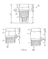
- Fig. 3 shows exemplary embodiments III and IV of the ceramic implant in partial schematics with the proximal part C and the intermediate region B having a Einwindgeometrie 5, an optional extension zone 4 and an optional spacer zone 24 and with an incomplete illustrated threaded portion A, of which a distal part of the thread and the distal end of the threaded portion A are not drawn.
- the proximal part C of the embodiments III and IV is configured identically and has a ball anchor, for example, a Lockball male part for a commercial matrix.
- the Einfgeometrie (5) adjacent to the distal end of the proximal part of both embodiments III and IV does not have the same rotationally symmetrical outer structure, here for example an equal thickness with the same outer radii r 1 and the same inner radii r 2 .
- the two exemplary embodiments of the ceramic implant III and IV have a different double outer radius r A of the thread 1 and thus a different implant diameter at the proximal end of the thread.
- This difference is, for example, less than 1 mm, in particular 0.1 mm to 0.8 mm or 0.2 to 0.6 mm or 0.3 to 0.5, for example 0.4 mm.
- the outer radii r 1 of Einfilgeometrien 5 of the embodiments shown by way of example III and IV are the same size as the radius r T of the extension zone 4 at its proximal end.
- the inner radii r 2 of the non-rotationally symmetrical outer structure of Einfilgeometrien 5 of the exemplary embodiments III and IV are, for example, 0.025 mm to 0.3 mm smaller than the outer radii r 1 in particular 0.05 mm to 0.15 mm or 0.07 to 0.1 mm smaller than the outer radii r 1 and as the radius r T at the proximal end of the extension zone 4.
- the outer radius r 1 of the outer structure of Eincoolgeometrie measures for example 1.5 mm to 2.5 mm, in particular 1.8 mm to 2.2 mm.
- a diameter d 5 of the Eincardgeometrie measures for example 3.5 to 5 mm, in particular 3.8 mm to 4.7 mm or 4 mm to 4.5 mm.
- the two in Fig. 3 illustrated embodiments of the ceramic implant are included in an exemplary ceramic implant system in which the different configuration of the extension zones 4 is tuned to the different thread diameter, that the extension zone of both embodiments III and IV at its distal end has an implant diameter which is the same size as the respective Implant diameter at the proximal End of the threaded portion or as the double outer radius r A of the thread and that the extension zone has at its proximal end an implant diameter which is equal to the same double outer radius r 1 of the same outer structure of Eincardgeometrie. 5
- Exemplary embodiments III and IV of the exemplary ceramic implant system include, in addition to the extension zone 4 in the intermediate region B, an optional clearance zone 24 disposed between the proximal end of the threaded region A and the distal end of the extension zone 4.
- the implant diameter does not expand in comparison to the implant diameter at the proximal end of the threaded region and, in particular, as in the embodiments III and IV, it is the same size as twice the outer radius r A of the thread.
- Fig. 4 shows schematic partial views of three further exemplary ceramic implants V, which have a locator male in the proximal region.
- Such and optionally further embodiments of the ceramic implant are contained, for example, in a ceramic implant system.
- Some embodiments of the ceramic implant with a locator male have an axial length of the threaded portion A of, for example, 8 to 12 mm, in particular 8.5 mm, 9.0 mm, 9.5 mm or 10.0 mm to 10.5 mm, 11.0 mm or 11.5 mm, an axial length of Intermediate area B for different gingiva heights of, for example, 2 mm to 5 mm, in particular 2.5 mm, 3.0 mm or 3.5 mm to 3.5 mm, 4.0 mm or 4.5 mm and the proximal region of for example 2.5 to 4.5, in particular 3.0 to 4.0 mm.
- the implant diameter of these embodiments in the proximal threaded area measures, for example, between 3 mm and 4.5 mm, in particular from 3.5 mm to 4.0 mm.
- the intermediate region B is in some embodiments, such as ceramic implants V, VI and VII in FIG Fig. 4 designed without expansion zone and without a clearance zone over its entire axial length as non-rotationally symmetrical Einwindgeometrie.
- the axial lengths of Eincoolgeometrien 5 are between 2 and 5 mm, those of the drawn implants V, VI and VII measure, for example, 2.5 mm, 3.5 mm and 4.5 mm.
- the intermediate region is not designed over the entire axial length as Einfilgeometrie and additionally has a clearance zone and or an extension zone.
- the outer radius of Einfilgeometrie 5 is greater than the outer radius of the thread.
- Fig. 5 shows a cross section through the Einfgeometrie 5 in the FIGS. 1 to 4 Exemplary embodiments of the ceramic implant
- This Einfgeometrie 5 is formed as a non-rotationally symmetrical outer structure, for example in the form of a constant thickness 13.
- a constant thickness 13 which is a regular uniform thickness, based on a regular pentagon with an angle ⁇ of 72 °, with a width 14 which is defined to be constant.
- the measure of the constant width 14 is, for example, in one range with a lower limit of 3, 3.25, 3.5, 3.75 4, 4.25, 4.5, 4.75 or 5.0 mm and an upper limit in a range of 4.5, 4.75, 5.0, 5.5, 5.75 or 6 mm and is in particular in the range from 3.5 to 5.5 mm.
- Einwindgeometrie 5 in the intermediate region B is the non-rotationally symmetrical outer structure, for example, an irregular uniform thickness or an outer edge.
- the implant diameter of the insertion geometry measures, for example, 3.5 to 6 mm, in particular 4 to 5 mm.
- FIGS. 1a . 1b . 2 and 3 show that the Einfgeometrie 5 is set back in the exemplary embodiments Ia, Ib and II to IV compared to the distal adjacent extension zone 4, that is, the outer radius r 1 of the non-rotationally symmetrical Eindeckgeometrie is smaller or in particular the same size as the outer radius r T the distally adjacent extension zone 4, and the inner radius r 2 of Einfgeometrie 5 is smaller than the outer radius r T of the distal adjacent extension zone 4.
- the implant diameter d 5 of the recessed insertion geometry 5 is smaller than the implant diameter of the implant region adjoining the insertion geometry 5 distally, such as, for example, a distal one adjacent extension zone 4, a distally adjacent spacer zone 24 or a distally adjacent threaded section A.
- the insertion geometry 5 protrudes from an implant region distally adjacent to the insertion geometry 5, such as against a distally adjacent extension zone 4, a distally adjacent spacer zone 24 or a distally adjacent threaded section A.
- the implant diameter d 5 of Einwindgeometrie 5 larger and in particular the outer radius r 1 of the outer structure of Eincardgeometrie 5 greater than the diameter or the largest radius in a sectional surface perpendicular to the axis through the ceramic implant immediately distal Einfilgeometrie at the proximal end, for example, the optional extension zone 4 or the optional distance zone 24 or threaded portion A.
- Embodiments V, VI and VII of the ceramic implant shown in FIG Fig. 4 have such opposite to the distally adjacent spacing zone projecting Eincardgeometrie 5.
- Fig. 6 shows a cross-section through an exemplary embodiment of a part 15 of a multi-part structural element of a dental implant system.
- the part 15 is a retaining element which can be fastened in the proximal region C of the ceramic implant and which can be connected to at least one further part of the structural element and, for example, holds a dental prosthesis such as a bridge, prosthesis or tooth crown.
- Exemplary holding element 15 is designed as a die and has a hemispherical cavity 16 for receiving the head 8 of the Ball anchor 7, wherein the diameter d 16 of the cavity 16 is adapted to the head diameter d 8 .
- the holding element 15 embodied as a die has a recess 17 for a snap element 18, for example for a snap ring, which is inserted into the depression 17 between the surface of the ceramic implant and the inner wall of the matrix, in particular in the region of the constriction 9 of the ceramic implant.
Landscapes
- Health & Medical Sciences (AREA)
- Oral & Maxillofacial Surgery (AREA)
- Veterinary Medicine (AREA)
- Epidemiology (AREA)
- Life Sciences & Earth Sciences (AREA)
- Animal Behavior & Ethology (AREA)
- General Health & Medical Sciences (AREA)
- Public Health (AREA)
- Dentistry (AREA)
- Orthopedic Medicine & Surgery (AREA)
- Ceramic Engineering (AREA)
- Engineering & Computer Science (AREA)
- Chemical & Material Sciences (AREA)
- Plastic & Reconstructive Surgery (AREA)
- Dental Prosthetics (AREA)
Applications Claiming Priority (1)
| Application Number | Priority Date | Filing Date | Title |
|---|---|---|---|
| CH00868/12A CH707052B1 (de) | 2012-06-20 | 2012-06-20 | Einstückiges keramisches Zahnimplantat, Keramikimplantatsystem, Zahnimplantatsystem und Set mit einen Zahnimplantats und einem Eindrehwerkzeug. |
Publications (1)
| Publication Number | Publication Date |
|---|---|
| EP2676632A1 true EP2676632A1 (fr) | 2013-12-25 |
Family
ID=48703390
Family Applications (1)
| Application Number | Title | Priority Date | Filing Date |
|---|---|---|---|
| EP13405073.1A Withdrawn EP2676632A1 (fr) | 2012-06-20 | 2013-06-18 | Implant céramique |
Country Status (3)
| Country | Link |
|---|---|
| US (1) | US9339444B2 (fr) |
| EP (1) | EP2676632A1 (fr) |
| CH (1) | CH707052B1 (fr) |
Families Citing this family (3)
| Publication number | Priority date | Publication date | Assignee | Title |
|---|---|---|---|---|
| US8747112B2 (en) | 2011-12-30 | 2014-06-10 | Nobel Biocare Services Ag | Abutment position locator |
| DE102013021934B4 (de) * | 2013-12-20 | 2017-09-14 | Hürzeler Zuhr Gmbh | Dentales Implantat |
| US20160015483A1 (en) | 2014-04-30 | 2016-01-21 | Osseodyne Surgical Solutions, LLC. | Osseointegrative surgical implant |
Citations (3)
| Publication number | Priority date | Publication date | Assignee | Title |
|---|---|---|---|---|
| EP0092209A2 (fr) * | 1982-04-19 | 1983-10-26 | Feldmühle Aktiengesellschaft | Pivot buccal implanté enrobé et procédé de fabrication |
| FR2571607A1 (fr) * | 1984-10-11 | 1986-04-18 | Texier Jean | Implant endo-osseux concu pour servir de pilier en bouche |
| US20060078847A1 (en) * | 2000-09-29 | 2006-04-13 | Kwan Norman H | Dental implant system and additional methods of attachment |
Family Cites Families (11)
| Publication number | Priority date | Publication date | Assignee | Title |
|---|---|---|---|---|
| US5246370A (en) * | 1992-11-27 | 1993-09-21 | Coatoam Gary W | Dental implant method |
| US5785525A (en) * | 1996-05-17 | 1998-07-28 | Weissman; Bernard | Dental implant system |
| US5759034A (en) * | 1996-11-29 | 1998-06-02 | Daftary; Fereidoun | Anatomical restoration dental implant system for posterior and anterior teeth |
| US6039568A (en) * | 1998-06-02 | 2000-03-21 | Hinds; Kenneth F. | Tooth shaped dental implants |
| US6312258B1 (en) * | 1999-08-19 | 2001-11-06 | Arthur Ashman | Kit for immediate post-extraction implantation |
| US6854972B1 (en) * | 2000-01-11 | 2005-02-15 | Nicholas Elian | Dental implants and dental implant/prosthetic tooth systems |
| JP2006512179A (ja) * | 2002-12-27 | 2006-04-13 | ワイスマン バーナード | 取り外し自在であり且つ調節自在の永久的義歯及びブリッジ用の構成要素の改良 |
| US7179088B2 (en) * | 2003-03-18 | 2007-02-20 | Cagenix, Inc. | Lobed dental implant |
| ATE380518T1 (de) * | 2004-05-19 | 2007-12-15 | Straumann Holding Ag | Einstückiges dentalimplantat und verfahren zu dessen herstellung |
| US7758344B2 (en) * | 2005-11-18 | 2010-07-20 | Form And Function Dental Services, P.C. | Asymmetrical dental implant and method of insertion |
| DE102008054186A1 (de) * | 2008-10-31 | 2010-05-12 | Böhm-van Diggelen, Bernd, Dr.med.dent. | Dentalimplantat sowie Verfahren zum Einbringen einer Ausnehmung in einen Kieferknochen, zur Insertion eines Implantats und zum Anbringen eines Zahnersatzes |
-
2012
- 2012-06-20 CH CH00868/12A patent/CH707052B1/de unknown
-
2013
- 2013-06-18 US US13/920,646 patent/US9339444B2/en active Active
- 2013-06-18 EP EP13405073.1A patent/EP2676632A1/fr not_active Withdrawn
Patent Citations (3)
| Publication number | Priority date | Publication date | Assignee | Title |
|---|---|---|---|---|
| EP0092209A2 (fr) * | 1982-04-19 | 1983-10-26 | Feldmühle Aktiengesellschaft | Pivot buccal implanté enrobé et procédé de fabrication |
| FR2571607A1 (fr) * | 1984-10-11 | 1986-04-18 | Texier Jean | Implant endo-osseux concu pour servir de pilier en bouche |
| US20060078847A1 (en) * | 2000-09-29 | 2006-04-13 | Kwan Norman H | Dental implant system and additional methods of attachment |
Also Published As
| Publication number | Publication date |
|---|---|
| CH707052B1 (de) | 2020-06-30 |
| US20140030676A1 (en) | 2014-01-30 |
| US9339444B2 (en) | 2016-05-17 |
| CH707052A2 (en) | 2014-03-31 |
Similar Documents
| Publication | Publication Date | Title |
|---|---|---|
| EP0984737B1 (fr) | Support pour maintenir et/ou former une prothese dentaire | |
| EP2667820B1 (fr) | Système de prothèse dentaire | |
| DE102005006979A1 (de) | Keramisches enossales Zahnimplantat | |
| EP1617783B1 (fr) | Implant dentaire | |
| EP2874564B1 (fr) | Système de construction d'implant dentaire | |
| EP1522271A2 (fr) | Dispositif pour maintenir et/ou former une prothèse dentaire | |
| EP2607722A1 (fr) | Vis de liaison pour un implant dentaire | |
| EP2674127B1 (fr) | Implant | |
| WO2018172265A1 (fr) | Système d'implant | |
| EP2328507B1 (fr) | Implant dentaire | |
| DE4326841A1 (de) | Implantat-Bausatz | |
| DE202008016218U1 (de) | Dentalimplantat mit koronaler Spannungsentlastung | |
| EP3386426B1 (fr) | Système d'implant dentaire | |
| EP2676632A1 (fr) | Implant céramique | |
| WO1996012451A1 (fr) | Systeme d'implant pour applications extra-orales et l'orthodontie | |
| WO2014091346A9 (fr) | Implant céramique en deux parties | |
| EP2811934B1 (fr) | Implant, notamment implant dentaire | |
| EP3914188B1 (fr) | Vis occlusale, système d'implant dentaire et ensemble | |
| CH703012A1 (de) | Dentalimplantat. | |
| EP2767254A2 (fr) | Système d'implant céramique | |
| EP3542751A1 (fr) | Système d'implant dentaire | |
| EP2856966A1 (fr) | Implant dentaire élastique | |
| WO2008155136A1 (fr) | Partie formant montant à insérer dans un os | |
| WO2014203225A1 (fr) | Implant dentaire pourvu d'un pilier court |
Legal Events
| Date | Code | Title | Description |
|---|---|---|---|
| PUAI | Public reference made under article 153(3) epc to a published international application that has entered the european phase |
Free format text: ORIGINAL CODE: 0009012 |
|
| AK | Designated contracting states |
Kind code of ref document: A1 Designated state(s): AL AT BE BG CH CY CZ DE DK EE ES FI FR GB GR HR HU IE IS IT LI LT LU LV MC MK MT NL NO PL PT RO RS SE SI SK SM TR |
|
| AX | Request for extension of the european patent |
Extension state: BA ME |
|
| RBV | Designated contracting states (corrected) |
Designated state(s): AL AT BE BG CH CY CZ DE DK EE ES FI FR GB GR HR HU IE IS IT LI LT LU LV MC MK MT NL NO PL PT RO RS SE SI SK SM TR |
|
| 17P | Request for examination filed |
Effective date: 20140617 |
|
| 17Q | First examination report despatched |
Effective date: 20160906 |
|
| STAA | Information on the status of an ep patent application or granted ep patent |
Free format text: STATUS: EXAMINATION IS IN PROGRESS |
|
| STAA | Information on the status of an ep patent application or granted ep patent |
Free format text: STATUS: THE APPLICATION IS DEEMED TO BE WITHDRAWN |
|
| 18D | Application deemed to be withdrawn |
Effective date: 20170317 |