EP2162173B1 - Seringue rétractable préremplie, piston et ensemble aiguille pour ladite seringue - Google Patents
Seringue rétractable préremplie, piston et ensemble aiguille pour ladite seringue Download PDFInfo
- Publication number
- EP2162173B1 EP2162173B1 EP08757038.8A EP08757038A EP2162173B1 EP 2162173 B1 EP2162173 B1 EP 2162173B1 EP 08757038 A EP08757038 A EP 08757038A EP 2162173 B1 EP2162173 B1 EP 2162173B1
- Authority
- EP
- European Patent Office
- Prior art keywords
- needle
- plunger
- retractable
- syringe
- barrel
- Prior art date
- Legal status (The legal status is an assumption and is not a legal conclusion. Google has not performed a legal analysis and makes no representation as to the accuracy of the status listed.)
- Active
Links
Images


Classifications
-
- A—HUMAN NECESSITIES
- A61—MEDICAL OR VETERINARY SCIENCE; HYGIENE
- A61M—DEVICES FOR INTRODUCING MEDIA INTO, OR ONTO, THE BODY; DEVICES FOR TRANSDUCING BODY MEDIA OR FOR TAKING MEDIA FROM THE BODY; DEVICES FOR PRODUCING OR ENDING SLEEP OR STUPOR
- A61M5/00—Devices for bringing media into the body in a subcutaneous, intra-vascular or intramuscular way; Accessories therefor, e.g. filling or cleaning devices, arm-rests
- A61M5/50—Devices for bringing media into the body in a subcutaneous, intra-vascular or intramuscular way; Accessories therefor, e.g. filling or cleaning devices, arm-rests having means for preventing re-use, or for indicating if defective, used, tampered with or unsterile
-
- A—HUMAN NECESSITIES
- A61—MEDICAL OR VETERINARY SCIENCE; HYGIENE
- A61M—DEVICES FOR INTRODUCING MEDIA INTO, OR ONTO, THE BODY; DEVICES FOR TRANSDUCING BODY MEDIA OR FOR TAKING MEDIA FROM THE BODY; DEVICES FOR PRODUCING OR ENDING SLEEP OR STUPOR
- A61M5/00—Devices for bringing media into the body in a subcutaneous, intra-vascular or intramuscular way; Accessories therefor, e.g. filling or cleaning devices, arm-rests
- A61M5/178—Syringes
- A61M5/31—Details
- A61M5/32—Needles; Details of needles pertaining to their connection with syringe or hub; Accessories for bringing the needle into, or holding the needle on, the body; Devices for protection of needles
- A61M5/3205—Apparatus for removing or disposing of used needles or syringes, e.g. containers; Means for protection against accidental injuries from used needles
- A61M5/321—Means for protection against accidental injuries by used needles
- A61M5/322—Retractable needles, i.e. disconnected from and withdrawn into the syringe barrel by the piston
- A61M5/3232—Semi-automatic needle retraction, i.e. in which triggering of the needle retraction requires a deliberate action by the user, e.g. manual release of spring-biased retraction means
-
- A—HUMAN NECESSITIES
- A61—MEDICAL OR VETERINARY SCIENCE; HYGIENE
- A61M—DEVICES FOR INTRODUCING MEDIA INTO, OR ONTO, THE BODY; DEVICES FOR TRANSDUCING BODY MEDIA OR FOR TAKING MEDIA FROM THE BODY; DEVICES FOR PRODUCING OR ENDING SLEEP OR STUPOR
- A61M5/00—Devices for bringing media into the body in a subcutaneous, intra-vascular or intramuscular way; Accessories therefor, e.g. filling or cleaning devices, arm-rests
- A61M5/178—Syringes
- A61M5/31—Details
- A61M5/32—Needles; Details of needles pertaining to their connection with syringe or hub; Accessories for bringing the needle into, or holding the needle on, the body; Devices for protection of needles
- A61M5/3205—Apparatus for removing or disposing of used needles or syringes, e.g. containers; Means for protection against accidental injuries from used needles
- A61M5/321—Means for protection against accidental injuries by used needles
- A61M5/322—Retractable needles, i.e. disconnected from and withdrawn into the syringe barrel by the piston
- A61M5/3234—Fully automatic needle retraction, i.e. in which triggering of the needle does not require a deliberate action by the user
-
- A—HUMAN NECESSITIES
- A61—MEDICAL OR VETERINARY SCIENCE; HYGIENE
- A61M—DEVICES FOR INTRODUCING MEDIA INTO, OR ONTO, THE BODY; DEVICES FOR TRANSDUCING BODY MEDIA OR FOR TAKING MEDIA FROM THE BODY; DEVICES FOR PRODUCING OR ENDING SLEEP OR STUPOR
- A61M5/00—Devices for bringing media into the body in a subcutaneous, intra-vascular or intramuscular way; Accessories therefor, e.g. filling or cleaning devices, arm-rests
- A61M5/178—Syringes
- A61M5/24—Ampoule syringes, i.e. syringes with needle for use in combination with replaceable ampoules or carpules, e.g. automatic
-
- A—HUMAN NECESSITIES
- A61—MEDICAL OR VETERINARY SCIENCE; HYGIENE
- A61M—DEVICES FOR INTRODUCING MEDIA INTO, OR ONTO, THE BODY; DEVICES FOR TRANSDUCING BODY MEDIA OR FOR TAKING MEDIA FROM THE BODY; DEVICES FOR PRODUCING OR ENDING SLEEP OR STUPOR
- A61M5/00—Devices for bringing media into the body in a subcutaneous, intra-vascular or intramuscular way; Accessories therefor, e.g. filling or cleaning devices, arm-rests
- A61M5/178—Syringes
- A61M5/31—Details
- A61M5/315—Pistons; Piston-rods; Guiding, blocking or restricting the movement of the rod or piston; Appliances on the rod for facilitating dosing ; Dosing mechanisms
-
- A—HUMAN NECESSITIES
- A61—MEDICAL OR VETERINARY SCIENCE; HYGIENE
- A61M—DEVICES FOR INTRODUCING MEDIA INTO, OR ONTO, THE BODY; DEVICES FOR TRANSDUCING BODY MEDIA OR FOR TAKING MEDIA FROM THE BODY; DEVICES FOR PRODUCING OR ENDING SLEEP OR STUPOR
- A61M5/00—Devices for bringing media into the body in a subcutaneous, intra-vascular or intramuscular way; Accessories therefor, e.g. filling or cleaning devices, arm-rests
- A61M5/178—Syringes
- A61M5/31—Details
- A61M5/32—Needles; Details of needles pertaining to their connection with syringe or hub; Accessories for bringing the needle into, or holding the needle on, the body; Devices for protection of needles
-
- A—HUMAN NECESSITIES
- A61—MEDICAL OR VETERINARY SCIENCE; HYGIENE
- A61M—DEVICES FOR INTRODUCING MEDIA INTO, OR ONTO, THE BODY; DEVICES FOR TRANSDUCING BODY MEDIA OR FOR TAKING MEDIA FROM THE BODY; DEVICES FOR PRODUCING OR ENDING SLEEP OR STUPOR
- A61M5/00—Devices for bringing media into the body in a subcutaneous, intra-vascular or intramuscular way; Accessories therefor, e.g. filling or cleaning devices, arm-rests
- A61M5/178—Syringes
- A61M5/31—Details
- A61M2005/3103—Leak prevention means for distal end of syringes, i.e. syringe end for mounting a needle
-
- A—HUMAN NECESSITIES
- A61—MEDICAL OR VETERINARY SCIENCE; HYGIENE
- A61M—DEVICES FOR INTRODUCING MEDIA INTO, OR ONTO, THE BODY; DEVICES FOR TRANSDUCING BODY MEDIA OR FOR TAKING MEDIA FROM THE BODY; DEVICES FOR PRODUCING OR ENDING SLEEP OR STUPOR
- A61M5/00—Devices for bringing media into the body in a subcutaneous, intra-vascular or intramuscular way; Accessories therefor, e.g. filling or cleaning devices, arm-rests
- A61M5/178—Syringes
- A61M5/31—Details
- A61M5/32—Needles; Details of needles pertaining to their connection with syringe or hub; Accessories for bringing the needle into, or holding the needle on, the body; Devices for protection of needles
- A61M5/3205—Apparatus for removing or disposing of used needles or syringes, e.g. containers; Means for protection against accidental injuries from used needles
- A61M5/321—Means for protection against accidental injuries by used needles
- A61M5/322—Retractable needles, i.e. disconnected from and withdrawn into the syringe barrel by the piston
- A61M5/3221—Constructional features thereof, e.g. to improve manipulation or functioning
- A61M2005/323—Connection between plunger distal end and needle hub proximal end, e.g. stud protruding from the plunger
-
- A—HUMAN NECESSITIES
- A61—MEDICAL OR VETERINARY SCIENCE; HYGIENE
- A61M—DEVICES FOR INTRODUCING MEDIA INTO, OR ONTO, THE BODY; DEVICES FOR TRANSDUCING BODY MEDIA OR FOR TAKING MEDIA FROM THE BODY; DEVICES FOR PRODUCING OR ENDING SLEEP OR STUPOR
- A61M5/00—Devices for bringing media into the body in a subcutaneous, intra-vascular or intramuscular way; Accessories therefor, e.g. filling or cleaning devices, arm-rests
- A61M5/178—Syringes
- A61M5/31—Details
- A61M5/32—Needles; Details of needles pertaining to their connection with syringe or hub; Accessories for bringing the needle into, or holding the needle on, the body; Devices for protection of needles
- A61M5/3205—Apparatus for removing or disposing of used needles or syringes, e.g. containers; Means for protection against accidental injuries from used needles
- A61M5/321—Means for protection against accidental injuries by used needles
- A61M5/322—Retractable needles, i.e. disconnected from and withdrawn into the syringe barrel by the piston
- A61M5/3221—Constructional features thereof, e.g. to improve manipulation or functioning
- A61M2005/3231—Proximal end of needle captured or embedded inside piston head, e.g. by friction or hooks
-
- A—HUMAN NECESSITIES
- A61—MEDICAL OR VETERINARY SCIENCE; HYGIENE
- A61M—DEVICES FOR INTRODUCING MEDIA INTO, OR ONTO, THE BODY; DEVICES FOR TRANSDUCING BODY MEDIA OR FOR TAKING MEDIA FROM THE BODY; DEVICES FOR PRODUCING OR ENDING SLEEP OR STUPOR
- A61M5/00—Devices for bringing media into the body in a subcutaneous, intra-vascular or intramuscular way; Accessories therefor, e.g. filling or cleaning devices, arm-rests
- A61M5/178—Syringes
- A61M5/31—Details
- A61M5/32—Needles; Details of needles pertaining to their connection with syringe or hub; Accessories for bringing the needle into, or holding the needle on, the body; Devices for protection of needles
- A61M5/3205—Apparatus for removing or disposing of used needles or syringes, e.g. containers; Means for protection against accidental injuries from used needles
- A61M5/321—Means for protection against accidental injuries by used needles
- A61M5/322—Retractable needles, i.e. disconnected from and withdrawn into the syringe barrel by the piston
- A61M5/3234—Fully automatic needle retraction, i.e. in which triggering of the needle does not require a deliberate action by the user
- A61M2005/3235—Fully automatic needle retraction, i.e. in which triggering of the needle does not require a deliberate action by the user triggered by radial deflection of the anchoring parts between needle mount and syringe barrel or needle housing, e.g. spreading of needle mount retaining hooks having slanted surfaces by engagement with correspondingly shaped surfaces on the piston at the end of an injection stroke
- A61M2005/3238—Trigger provided at the proximal end, i.e. syringe end opposite to needle mounting end
-
- A—HUMAN NECESSITIES
- A61—MEDICAL OR VETERINARY SCIENCE; HYGIENE
- A61M—DEVICES FOR INTRODUCING MEDIA INTO, OR ONTO, THE BODY; DEVICES FOR TRANSDUCING BODY MEDIA OR FOR TAKING MEDIA FROM THE BODY; DEVICES FOR PRODUCING OR ENDING SLEEP OR STUPOR
- A61M5/00—Devices for bringing media into the body in a subcutaneous, intra-vascular or intramuscular way; Accessories therefor, e.g. filling or cleaning devices, arm-rests
- A61M5/50—Devices for bringing media into the body in a subcutaneous, intra-vascular or intramuscular way; Accessories therefor, e.g. filling or cleaning devices, arm-rests having means for preventing re-use, or for indicating if defective, used, tampered with or unsterile
- A61M5/5066—Means for preventing re-use by disconnection of piston and piston-rod
- A61M2005/5073—Means for preventing re-use by disconnection of piston and piston-rod by breaking or rupturing the connection parts
-
- A—HUMAN NECESSITIES
- A61—MEDICAL OR VETERINARY SCIENCE; HYGIENE
- A61M—DEVICES FOR INTRODUCING MEDIA INTO, OR ONTO, THE BODY; DEVICES FOR TRANSDUCING BODY MEDIA OR FOR TAKING MEDIA FROM THE BODY; DEVICES FOR PRODUCING OR ENDING SLEEP OR STUPOR
- A61M2205/00—General characteristics of the apparatus
- A61M2205/58—Means for facilitating use, e.g. by people with impaired vision
- A61M2205/581—Means for facilitating use, e.g. by people with impaired vision by audible feedback
-
- A—HUMAN NECESSITIES
- A61—MEDICAL OR VETERINARY SCIENCE; HYGIENE
- A61M—DEVICES FOR INTRODUCING MEDIA INTO, OR ONTO, THE BODY; DEVICES FOR TRANSDUCING BODY MEDIA OR FOR TAKING MEDIA FROM THE BODY; DEVICES FOR PRODUCING OR ENDING SLEEP OR STUPOR
- A61M2205/00—General characteristics of the apparatus
- A61M2205/58—Means for facilitating use, e.g. by people with impaired vision
- A61M2205/582—Means for facilitating use, e.g. by people with impaired vision by tactile feedback
-
- A—HUMAN NECESSITIES
- A61—MEDICAL OR VETERINARY SCIENCE; HYGIENE
- A61M—DEVICES FOR INTRODUCING MEDIA INTO, OR ONTO, THE BODY; DEVICES FOR TRANSDUCING BODY MEDIA OR FOR TAKING MEDIA FROM THE BODY; DEVICES FOR PRODUCING OR ENDING SLEEP OR STUPOR
- A61M5/00—Devices for bringing media into the body in a subcutaneous, intra-vascular or intramuscular way; Accessories therefor, e.g. filling or cleaning devices, arm-rests
- A61M5/178—Syringes
- A61M5/31—Details
- A61M5/315—Pistons; Piston-rods; Guiding, blocking or restricting the movement of the rod or piston; Appliances on the rod for facilitating dosing ; Dosing mechanisms
- A61M5/31511—Piston or piston-rod constructions, e.g. connection of piston with piston-rod
-
- A—HUMAN NECESSITIES
- A61—MEDICAL OR VETERINARY SCIENCE; HYGIENE
- A61M—DEVICES FOR INTRODUCING MEDIA INTO, OR ONTO, THE BODY; DEVICES FOR TRANSDUCING BODY MEDIA OR FOR TAKING MEDIA FROM THE BODY; DEVICES FOR PRODUCING OR ENDING SLEEP OR STUPOR
- A61M5/00—Devices for bringing media into the body in a subcutaneous, intra-vascular or intramuscular way; Accessories therefor, e.g. filling or cleaning devices, arm-rests
- A61M5/178—Syringes
- A61M5/31—Details
- A61M5/32—Needles; Details of needles pertaining to their connection with syringe or hub; Accessories for bringing the needle into, or holding the needle on, the body; Devices for protection of needles
- A61M5/3202—Devices for protection of the needle before use, e.g. caps
-
- A—HUMAN NECESSITIES
- A61—MEDICAL OR VETERINARY SCIENCE; HYGIENE
- A61M—DEVICES FOR INTRODUCING MEDIA INTO, OR ONTO, THE BODY; DEVICES FOR TRANSDUCING BODY MEDIA OR FOR TAKING MEDIA FROM THE BODY; DEVICES FOR PRODUCING OR ENDING SLEEP OR STUPOR
- A61M5/00—Devices for bringing media into the body in a subcutaneous, intra-vascular or intramuscular way; Accessories therefor, e.g. filling or cleaning devices, arm-rests
- A61M5/178—Syringes
- A61M5/31—Details
- A61M5/32—Needles; Details of needles pertaining to their connection with syringe or hub; Accessories for bringing the needle into, or holding the needle on, the body; Devices for protection of needles
- A61M5/34—Constructions for connecting the needle, e.g. to syringe nozzle or needle hub
- A61M5/344—Constructions for connecting the needle, e.g. to syringe nozzle or needle hub using additional parts, e.g. clamping rings or collets
- A61M5/345—Adaptors positioned between needle hub and syringe nozzle
-
- Y—GENERAL TAGGING OF NEW TECHNOLOGICAL DEVELOPMENTS; GENERAL TAGGING OF CROSS-SECTIONAL TECHNOLOGIES SPANNING OVER SEVERAL SECTIONS OF THE IPC; TECHNICAL SUBJECTS COVERED BY FORMER USPC CROSS-REFERENCE ART COLLECTIONS [XRACs] AND DIGESTS
- Y10—TECHNICAL SUBJECTS COVERED BY FORMER USPC
- Y10T—TECHNICAL SUBJECTS COVERED BY FORMER US CLASSIFICATION
- Y10T29/00—Metal working
- Y10T29/49—Method of mechanical manufacture
- Y10T29/49826—Assembling or joining
Definitions
- THIS INVENTION relates to syringes. More particularly, this invention relates to a retractable syringe that includes a needle retraction mechanism to prevent re-use of the syringe and/or needle stick injury, wherein the needle retraction mechanism acts in a controlled manner.
- HIV Human Immunodeficiency Virus
- retractable syringes have been developed with the aim of preventing syringe re-use and/or needlestick injury by used syringes.
- an objective is to reduce manufacturing costs and/or maintain ease of use and/or syringe safety. These are important factors if safety syringes are to be available for mass consumption, particularly in third world countries with low health budgets.
- a preferred object of the invention is to provide a user friendly and safe retractable syringe while keeping manufacturing costs to a minimum, thereby facilitating mass distribution of retractable syringes.
- the invention provides a plunger for a retractable syringe, said plunger comprising a plunger rod, a plunger outer, a controlling member and a biasing member, wherein the plunger rod, plunger outer and the controlling member co-operate to releasably maintain said biasing member in an initially energized state.
- the invention provides a retractable syringe comprising a barrel; a retractable needle; and a plunger engageable with said retractable needle, said plunger comprising a plunger rod, a plunger outer, a controlling member and a biasing member, wherein the plunger rod, plunger outer and the controlling member co-operate to releasably maintain said biasing member in an initially energized state.
- the invention provides a releasable needle retaining system comprising: a retractable needle and a retaining member mounted to an interior wall of a syringe barrel, or formed inttegrally therewith, said retaining member capable of initially retaining said retractable needle at a needle end of said barrel until said retractable needle is engaged by a plunger to facilitate retraction of said retractable needle.
- the invention provides a retractable syringe comprising a barrel; a releasable needle retaining system that comprises a retractable needle and a retaining member mounted to an interior wall of a syringe barrel, or formed inttegrally therewith; and a plunger engageable with said retractable needle; said retaining member capable of initially retaining said retractable needle at a needle end of said barrel until said retractable needle is engaged by said plunger to facilitate retraction of said retractable needle.
- the syringe according to the aforementioned aspects is a prefilled syringe.
- the plunger further comprises a plunger seal which is capable of engaging said retractable needle.
- the plunger seal is a unitary plunger seal.
- the controlling member facilitates control of the rate of retraction of said retractable needle when engaged with said plunger and is removable from said plunger following needle retraction.
- said controlling member comprises one or more mating portions that initially engage said plunger outer to facilitate maintaining said biasing member in an initially energized state.
- said controlling member comprises one or more arm members that initially engage said plunger outer to facilitate maintaining said biasing member in an initially energized state.
- said controlling member comprises one or more cutaways, notches or recesses that initially engage said plunger outer to facilitate maintaining said biasing member in an initially energized state.
- said biasing member such as a spring, elastic or other device for storing energy.
- the biasing member is a spring.
- the spring is initially compressed so that decompression of said spring facilitates retraction of said retractable needle.
- the retaining member comprises a mating surface complementary to a mating surface of the interior wall of the syringe barrel.
- the releasable needle retaining system further comprises a needle seal.
- the retractable needle comprises a retractable needle body and a cannula.
- the releasable needle retaining system further comprises an ejector member which facilitates release of the retractable needle from the retaining member to facilitate retraction of said retractable needle when engaged by said plunger.
- the barrel is formed of glass.
- said barrel further comprises a collar having one or more releasing members that facilitate release of said controlling member from said plunger outer.
- said syringe or said plunger comprises at least one locking system which prevents re-use of the syringe at the end of needle retraction.
- one said locking system comprises respective elements of said barrel and said plunger outer.
- the locking system comprises elements of said collar and said plunger outer.
- another said locking system comprises elements of said plunger rod and said plunger outer.
- said syringe comprises both said locking systems.
- the invention provides a prefilled retractable syringe comprising:
- the invention also relates to a method of assembly of the aforementioned plunger, releasable needle retaining assembly and/or syringe and to a method of use of the aforementioned syringe.
- the method of assembly of the syringe includes the sequential steps of:
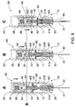
- retractable syringe 10 comprises barrel 11 and plunger 20 having plunger seal 80 mounted to plunger 20.
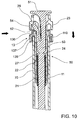
- Barrel 11 is formed of glass and comprises plunger end 14 at which is located collar 13, and needle end 15 in which is mounted releasable needle retaining system 90 comprising retractable needle 40 that comprises cannula 41 and retractable needle body 42, needle seal 43, ejector member 60 and retaining member 30.
- releasable needle retaining system 90 comprising retractable needle 40 that comprises cannula 41 and retractable needle body 42, needle seal 43, ejector member 60 and retaining member 30.
- At needle end 15 is also protective cover 12 for cannula 41.
- Collar 13 may be mounted or otherwise fitted to barrel 11, or co-moulded with barrel 11.
- Barrel 11 further comprises inside wall 18 which, together with needle seal 43 and plunger seal 80 define fluid space 105 inside barrel 11.
- Retaining member 30 has a relatively smooth ouside diameter (OD) comprising a mating surface which fits flush with complementary mating surface of internal wall 18 of barrel.
- OD ouside diameter
- retaining member 30 is glued or otherwise adhered to glass barrel 11. This arrangement obviates the need to include complementary grooves, ribs or comoulding (for example) to hold retaining member 30 in barrel 11, thereby improving the ease with which retractable syringe 10 is manufactured and assembled.
- plunger 20 is movable axially into fluid space 105 to facilitate delivery of fluid contents of retractable syringe 10.
- fluid space 105 is prefilled with the fluid contents to be delivered by retractable syringe 10.
- a non-limiting example of fluid contents is a low molecular weight heparin such as enoxaparin sodium (e.g. Lovenox®).
- plunger 20 comprises plunger rod 21 and plunger outer 22 having cap member 23. Releasably engaged with plunger 20 is controlling member 50 comprising button 51, arm 52 and shaft 53. Plunger 20 further comprises compressed spring 70 which is mounted between plunger rod 21 and plunger outer 22, held in a compressed state between annular ledge 27 of plunger rod 21 and base 28 of plunger outer 22.
- Plunger rod 21 further comprises seal engaging member 26, which in this embodiment is a screw threaded projection, which engages complementary recess 82 of plunger seal 80.
- seal engaging member 26 may be in the form of a snap lock projection that engages a complementary recess in plunger seal 80.
- controlling member 50 is releasably coupled to plunger rod 21 by way of shaft 53 which comprises frangible junction 24 with plunger rod 21.
- shaft 53 which comprises frangible junction 24 with plunger rod 21.
- the frangible engagement between controlling member 50 and plunger rod 21 applies minimal stress to frangible junction 24.
- Controlling member 50 also releasably engages plunger outer 22, which engagement retains spring 70 in an initially compressed state held between annular ledge 27 of plunger rod 21 and base 28 of plunger outer 22.
- Initially ledge 54 of arm 52 abuts rim 29 of cap member 23 of plunger outer 22 to thereby retain controlling member 50 and prevent axial movement of controlling member relative to plunger outer 22.
- arm 52 of controlling member 50 is resiliently flexible and movable in the direction of the solid arrow shown in FIG. 3 , which will allow disengagement of controlling member 50 from plunger outer 22 to facilitate decompression of spring 70, as will be described in detail hereinafter.
- plunger seal 80 is of unitary construction and is mounted to plunger 20 to thereby provide a fluid seal between plunger 20 and inside wall 18 of barrel 11.
- Plunger seal 80 comprises seal body 84 and circumferential ribs 85A, B, C that effect a fluid-tight seal between plunger 20 and inside wall 18 of barrel 11.
- Plunger seal 80 further comprises recessed seat 81 that receives base 405 of retractable needle body 42 and also needle recess 86 that receives cannula end 141 towards the end of plunger 20 depression, prior to retraction of retractable needle 40, as will be described hereinafter.
- releasable needle retaining system 90 comprising retractable needle 40 having cannula 41 and retractable needle body 42 and needle seal 43. End 141 of cannula 41 communicates with fluid contents in fluid space 105 of barrel 11.
- needle seal 43 comprises complementary steps 46 forming bore 44, that respectively receive steps 45 of retractable needle body 42, so that base 405 of retractable needle body 42 initially sits inside bore 44.
- retractable needle body 42 it is advantageous for retractable needle body 42 to have a tapered cross section, tapering toward cannula 41, and comprise plurality of steps 45.
- This stepped configuration means that the amount of movement required to dislodge retractable needle 40 from needle seal 43 is minimized.
- the taper may assist centering of retractable needle 40 when withdrawn from needle seal 43 in that resistance to withdrawal of retractable needle 40 effectively reduces as cross-sectionally tapered retractable needle body 42 is withdrawn through bore 44 of needle seal 43.
- Needle seal 43 also has annular rib 47 and annular base 48 that co-operate with inside wall 18 of barrel 11 to facilitate improved sealing performance and prevent inadvertent leakage of fluid contents.
- retaining member 30 is mounted inside needle end 15 of barrel 11, which as best seen in FIG. 6 , has a "smooth"mating surface to facilitate adhesion into the "smooth" mating surface of inside wall 18 of needle end 15 of barrel 11.
- retractable syringe 10 is made of glass.
- retaining member 30 is mounted by a circumferential rib (not shown) on inside wall 18 of barrel 11 engaging a circumferential groove (not shown) on retaining member 30.
- retaining member 30 could be co-moulded into needle end 15 of barrel 11.
- ejector member 60 which comprises ejector ring 61 and base 62.
- Ejector member 60 engages circumferential recess 420 on retractable needle body 42 via annular detent 63.
- Ejector member 60 is not fixed or positively mounted or engaged with needle seal 43, but simply bears against needle seal 43, unlike the corresponding arrangement in International Publication WO 2006/108243 .
- needle seal 43 and ejector member 60 may be co-moulded as a unitary structure.
- Retaining member 30 comprises cylindrical body 35 and fingers 31A, 31B, 31C that respectively comprise angled faces 32A, 32B, 32C (visible in FIG. 8 ) that abut ledge 491 of head 49 of retractable needle body 42 to releasably hold retractable needle 40 in position during operation of retractable syringe 10.
- Cylindrical body 35 of retaining member 30 further comprises internal tapered bosses 34A, 34B and 34C that engage head 49 of retractable needle body 42 to prevent retractable needle body 42 pushing out of barrel 11.
- FIG. 9 A-C The sequence of events whereby retractable needle 40 is disengaged from retaining member 30 to facilitate retraction of retractable needle 40 is shown in FIG. 9 A-C .
- retractable syringe 10 is provided prefilled with fluid contents for delivery. Therefore, plunger 20 is provided in an initial position ready for depression to deliver the fluid contents of the retractable syringe 10.
- plunger 20 moves plunger seal 80 coupled thereto against needle seal 43 at needle end 15 of barrel 11. This moves ejector member 60 so that it engages retaining member 30. Plunger 20 continues to move in the direction of the solid arrow so that recessed seat 81 receives base 405 of retractable needle body 42 and needle recess 86 receives cannula end 141. This effectively couples retractable needle body 42 to plunger 20.
- plunger seal 80 "squeezes out” the last of the delivered fluid as base 405 of retractable needle body 42 engages recessed seat 81. Testing has shown that deadspace (amount of fluid left in retractable syringe 10 after injection) averages less than 0.001g, which is more than acceptable for drug delivery.
- Release ring 136 forces arm 52 to move laterally in the direction of the horizontal solid arrow and out of engagement with rim 29 of cap member 23 of plunger outer 22.
- This disengagement allows compressed spring 70 to decompress and push against ledge 27 of plunger rod 21 to thereby retract plunger rod 21 with controlling member 50 coupled thereto.
- This disengagement may also be accompanied by an audible and/or tactile signal (e.g. a "click") which indicates to the user that retraction will occur.
- retractable needle 40 is coupled to plunger seal 80 and so retracts with plunger rod 21 in the direction of the arrow in FIG. 11 inside barrel 11, thereby being completely enveloped by, and contained within, barrel 11. While retraction of needle 40 is "automatically' driven by decompression of spring 70, the rate of retraction can be controlled by a user relaxing pressure (such as by way of thumb pressure) against button 51 of controlling member 50.
- controlling member 50 can be broken from plunger rod 21 at frangible junction 24 and manually removed from retractable syringe 10 and discarded as "clean" waste.
- plunger 20 One advantage of this embodiment of plunger 20 is that when controlling member 50 is broken away from plunger rod 21, it constitutes a relatively short piece of material for subsequent "clean" waste disposal.
- plunger 20 Another advantage of this embodiment of plunger 20 is that once controlling member 50 is broken away from plunger rod 21, there is little if any plunger 20 protruding externally from barrel 11 with which to attempt to force plunger 20 back into barrel 11 and re-engage the needle (not shown).
- Retractable syringe 10 may further comprise first locking system 95A and second locking system 95B to prevent re-use of retractable syringe 10.
- FIG. 12 An embodiment of locking system 95A is shown in FIG. 12 , where plunger outer 22 is locked into collar 13 to prevent withdrawal of plunger 20 from barrel 11 to extract retracted needle 40 and thereby prevents re-use of retractable syringe 10.
- complementary circumferential groove 137 of collar accommodates barrel lip 119.
- Adhesive or glue is applied to junction 138 between barrel 11 and collar 13.
- Plunger outer 22 comprises locking arms 299A, 299B that respectively engage locking rim 139 in collar 13. Locking arms 299A, 299B are oriented at approximately 150 degrees to each other to maximize strength of plunger outer 22.
- FIGS. 13 and 14 An embodiment of locking system 95B is shown in FIGS. 13 and 14 .
- plunger 20 of retractable syringe 10 comprises plunger rod 21, controlling member 50 and plunger outer 22.
- Controlling member 50 further comprises recess 57 that initially engages flexible tab 25 of plunger outer 22.
- Plunger rod 21 and controlling member 50 are releasably connected by way of frangible junction 24.
- recess 57 and flexible tab 25 are moulded into controlling member 50 and plunger outer 22, respectively.
- Depression of plunger 20 to expel the fluid contents of retractable syringe 10 is essentially as hereinbefore described.
- Decompression of spring 70 along with the angled face and the height of the angled face of flexible tab 25 i.e to prevent engaging in frangible junction 24
- flexible tab 25 to pass over retracting controlling member 50 and plunger rod 21 until flexible tab 25 of plunger outer 22 engages notch 27 on plunger rod 21 to thereby form second locking system, as shown in FIGS 13 and 14 .
- Second locking system is arranged so that plunger rod 21 and controlling member 50 coupled thereto cannot move back towards the inside of plunger outer 22 in the direction of the solid arrows shown in FIG. 14 . This prevents the retracted needle (not shown) from being re-exposed.
- retractable syringe 10 there are a number of manufacturing and design advantages provided by retractable syringe 10 and also variations that are contemplated within the broad scope of the present invention, primarily to assist manufacturing and design.
- barrel 11 is formed of glass with lip 119 at plunger end 14 instead of finger grips.
- Collar 13 may have finger grips 139A, 139B incorporated therein and is glued or otherwise adhered to glass barrel 11 as previously decribed (as seen in FIGS 10 and 12 ).
- An advantage is the underside of collar 13 will be a smooth continuous surface (no clips protruding below the glass finger grip) which is important in the fluid filling line where the syringes are guided and located through processing by the underside of finger grips 139A, 139B.
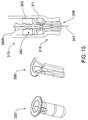
- FIGS. 15 and 16 Alternative embodiments of retaining member 30 are shown in FIGS. 15 and 16 , although these require more complicated tooling (sliders) the designs do provide a saving in overall length.
- FIG. 15 shows needle retaining member 330 which is self locking and assembled at needle end 315 of syringe 310. This may provide a potentially stronger resistance to inadvertently pushing retractable needle 340 into barrel 311 during injection.
- FIG. 16 shows another smaller retaining member 430 which is self locking but assembled distally to needle end 415 of syringe 410.
- Releasable needle retaining system 90 may also be varied.
- retractable needle 40 particularly retractable needle body 42
- retractable needle body 42 may be varied as shown in FIGS 17A , B & C where base 530 of retractable needle body 542 protrudes through needle seal 543 into the barrel fluid space 5105. This may stagger system forces and/or reduce overall plunger travel and/or provide a reduced force for plunger seal (not shown) to engage retractable needle body 542 as previously described.
- releasable needle retaining system 690 comprises needle seal 643 and ejector member 660 which holds retractable needle body 642 in place and retaining member 630 which serves to hold the retractable needle body 642 from moving forward.
- ejector member 660 is pushed off detent 6409 around retractable needle body 642 allowing it to be free to be retracted (rather than opening fingers 31A, 31B, 31C on retaining member 30 as previously described) to allow retraction of needle 640.
- shaft 753 may comprise a connector that releasably engages a recess in plunger rod 721, while otherwise being arranged as described in FIGS. 2 and 3 .
- controlling member 750 comprises a recess (not shown) which receives snap ring connector 729 on plunger rod 721.
- a preferred mode of assembly of a prefilled retractable syringe 10 is as follows. Retaining member 30 and collar 13 are both glued to barrel 11 which is then siliconised. Retractable needle 40, ejector member 60 and needle seal 43 of releasable needle retaining assembly 90 are fitted into needle end 15 of barrel 11. These three components are held together as an assembly by head 405 of retractable needle 40 being retained by needle seal 43 and ejector member 60 engaging circumferential recess 420 on retractable needle body 42 via annular detent 63. Retractable needle body 42 also clips into fingers 31A-C of retaining member 30. Protective cover 12 is then fitted to barrel 11 at needle end 15.
- Barrel 11 is then filled with fluid contents and plunger seal 80 is subsequently inserted inside barrel 11 to a position adjacent the fluid contents without pressurising the fluid contents.
- a nitrogen gas gap is located between the fluid contents and plunger seal 80.
- the fitting of plunger seal 80 thereby provides a sterile container for the fluid contents.
- Plunger outer 22, plunger rod 21 with controlling member 50 and spring 70 are preassembled into a plunger 20 assembly which is subsequently screw-fitted into plunger seal 80.
- Components of retractable syringe 10 have been designed to provide ease of manufacture to the extent that plastic components require only open-shut tooling (e.g. no sliders are required) which not only makes tooling less expensive and less complicated, but open/shut tools are much more reliable for high volume production.
- retractable syringe 10 considers the broader manufacturing tolerances of glass barrels (compared to plastic moulding tolerances) which have a length tolerance of +/- 0.5mm.
- retractable syringe 10 has been designed to allow the retaining member 30 to be glued into position at needle end 15 of barrel 11 with reference to collar 13 at plunger end 14 of barrel 11 to a tolerance of ⁇ 0.05mm. This reduces the tolerance effect of the glass barrel 11 to provide a tighter activation of the retractable needle 40 retraction mechanism that is activated by release ring 136 triggering spring 70 release whilst retractable needle 40 is being released from retaining member 30.
- ejector member 60 simply sits on needle seal 43 and also engages retractable needle body 42 via annular detent 63, which effectively locks the assembly of needle seal 43, ejector member 60 and retractable needle 40 together for assembly into glass barrel 11 as a unit.
- Retaining member 30 will already have been glued into place (at a set distance from collar 13) for location of retractable needle 40 as the assembly is moved into position in barrel 11.
- plunger 20 as hereinbefore described comprises plunger rod 21 and controlling member 50 as a single part, with controlling member 50 being snapped off at frangible junction 24 after retraction. This reduces the number of components and eliminates connection detail between these two components.
- the present invention provides a relatively simple, robust and inexpensive syringe that is automatically disabled with little or no assistance from the user to thereby prevent, or at least minimize the likelihood of, re-use of the syringe and/or needlestick injury by a used syringe.
- the likelihood of blood splattering is reduced thereby improving the "user-friendliness" and commercial appeal of the retractable syringe.
- the retractable syringe components are all designed to ensure the uniquely correct timing and efficient delivery of fluid contents, plunger engagement with the retractable needle and needle retraction as a particular feature of the syringe as herein described. Depression of the plunger rod "squeezes" the plunger seal lengthways against the needle seal which bears against the ejector member to ensure the ejector member has sufficiently spread the fingers of the retaining member to allow the retractable needle to be free to retract, but not before the last of the fluid contents have been delivered and the retractable needle securely engaged.
- retractable syringe sub-assembly comprising a barrel fitted with a releasable needle retaining system together with a plunger and a separate plunger seal
- a retractable syringe sub-assembly comprising a barrel fitted with a releasable needle retaining system together with a plunger and a separate plunger seal
Claims (14)
- Système libérable (90) de rétention d'aiguille pouvant être monté sur le cylindre (11) d'une seringue (10) rétractable qui comprend un piston (20), le système libérable (90) de rétention d'aiguille comprenant : une aiguille rétractable (40) qui comprend une canule (41), un corps (42) d'aiguille rétractable comprenant des pas (46) et une base (405) ; un joint d'étanchéité (43) d'aiguille comprenant des pas (46) complémentaires constituant un alésage (44) qui est en prise de façon amovible avec les pas (46) de sorte que la base (405) du corps (42) d'aiguille est logée au départ à l'intérieur de l'alésage (44) avant que le piston (20) n'entre en prise avec la base (405) pour faciliter la rentrée de l'aiguille rétractable (40) ; un élément de rétention (30) qui comprend une surface d'ajustement complémentaire d'une surface d'ajustement de la paroi intérieure (18) dudit cylindre (11), ledit élément de rétention (30) pouvant retenir au départ ladite aiguille rétractable (40) au niveau d'une extrémité (15) d'aiguille dudit cylindre (11) jusqu'à ce que ladite base (405) de ladite aiguille rétractable (40) soit solidaire du piston (20) pour faciliter la rentrée de ladite aiguille (40) ; et au niveau d'une extrémité (15) d'aiguille du cylindre (11),
caractérisé par un élément d'éjecteur (60) qui entre en prise avec le corps (42) de l'aiguille rétractable et facilite la libération de l'aiguille rétractable (40) de l'élément de rétention (30) et qui porte contre le joint d'étanchéité (43) d'aiguille, mais n'est pas fixe ou monté positivement ou solidaire du joint d'étanchéité (43) d'aiguille. - Système libérable (90) de rétention d'aiguille selon la revendication 1, qui peut être monté sur un cylindre (11) en verre.
- Système libérable (90) de rétention d'aiguille selon la revendication 2, dans lequel l'élément d'éjecteur (60) est capable de déformer l'élément de rétention (30) pour empêcher plus facilement la réutilisation de la seringue (10) rétractable après que l'aiguille rétractable (40) ait été libérée de l'élément de rétention (30).
- Seringue (10) rétractable, comprenant un cylindre (11), un piston (20) et un système libérable (90) de rétention d'aiguille selon l'une quelconque des revendications 1 à 3.
- Seringue (10) rétractable selon la revendication 4, dans laquelle le piston (20) comprend une tige (21) de piston, un extérieur (22) de piston, un élément de commande (50) et un élément de sollicitation (70), dans laquelle la tige (21) de piston, l'extérieur (22) de piston et l'élément de commande (50) coopèrent pour maintenir de façon amovible ledit élément de sollicitation (70) dans un état initial de travail.
- Seringue (10) rétractable selon la revendication 5, dans laquelle la tige (21) de piston comprend un joint d'étanchéité (80) unitaire capable d'entrer en prise avec ladite aiguille rétractable (40).
- Seringue (10) rétractable selon la revendication 5 ou 6, dans laquelle ledit élément de commande (50) comprend une ou plusieurs parties d'accouplement (52, 54) qui au départ sont en prise avec ledit extérieur (22) de piston pour faciliter le maintien dudit élément de sollicitation (70) dans un état initial de travail.
- Seringue (10) rétractable selon l'une quelconque des revendications 4 à 7, dans laquelle l'élément de sollicitation (70) est un ressort (70).
- Seringue (10) rétractable selon l'une quelconque des revendications 4 à 8, dans laquelle la tige (21) de piston et l'élément de commande (50) sont raccordés amovibles.
- Seringue (10) rétractable selon la revendication 9, dans laquelle la tige (21) de piston et l'élément de commande (50) sont raccordés par une liaison frangible.
- Seringue (10) rétractable selon l'une quelconque des revendications 4 à 10, comprenant en outre un système de verrouillage (95B) comprenant des éléments (25, 27) de l'extérieur (22) de piston et de la tige (21) de piston.
- Seringue (10) rétractable selon l'une quelconque des revendications 4 à 11, qui est une seringue (10) pré-remplie.
- Seringue (10) rétractable selon la revendication 12, qui est pré-remplie avec une solution injectable d'une héparine de faible poids moléculaire.
- Seringue (10) rétractable selon la revendication 4, comprenant en outre un système de verrouillage (95A) comprenant des éléments (299A, 299B, 139) d'un collier (13) monté sur le cylindre (11) et l'extérieur (22) de piston.
Applications Claiming Priority (3)
| Application Number | Priority Date | Filing Date | Title |
|---|---|---|---|
| AU2007903565A AU2007903565A0 (en) | 2007-07-02 | Prefilled retractable syringe | |
| US1264307P | 2007-12-10 | 2007-12-10 | |
| PCT/AU2008/000971 WO2009003234A1 (fr) | 2007-07-02 | 2008-07-02 | Seringue rétractable préremplie, piston et ensemble aiguille pour ladite seringue |
Publications (3)
| Publication Number | Publication Date |
|---|---|
| EP2162173A1 EP2162173A1 (fr) | 2010-03-17 |
| EP2162173A4 EP2162173A4 (fr) | 2013-09-11 |
| EP2162173B1 true EP2162173B1 (fr) | 2016-02-24 |
Family
ID=40225648
Family Applications (1)
| Application Number | Title | Priority Date | Filing Date |
|---|---|---|---|
| EP08757038.8A Active EP2162173B1 (fr) | 2007-07-02 | 2008-07-02 | Seringue rétractable préremplie, piston et ensemble aiguille pour ladite seringue |
Country Status (19)
| Country | Link |
|---|---|
| US (2) | US8361035B2 (fr) |
| EP (1) | EP2162173B1 (fr) |
| JP (2) | JP5192543B2 (fr) |
| KR (2) | KR101230434B1 (fr) |
| CN (2) | CN101730558B (fr) |
| AU (1) | AU2008271920B2 (fr) |
| BR (1) | BRPI0812986A2 (fr) |
| CA (2) | CA2692968C (fr) |
| DK (1) | DK2162173T3 (fr) |
| ES (1) | ES2569481T3 (fr) |
| HK (2) | HK1143770A1 (fr) |
| IL (1) | IL202736A (fr) |
| MX (1) | MX347849B (fr) |
| MY (2) | MY157157A (fr) |
| NZ (2) | NZ595031A (fr) |
| RU (1) | RU2450834C2 (fr) |
| TW (1) | TWI415646B (fr) |
| WO (1) | WO2009003234A1 (fr) |
| ZA (1) | ZA200909165B (fr) |
Families Citing this family (48)
| Publication number | Priority date | Publication date | Assignee | Title |
|---|---|---|---|---|
| NL2001702C2 (nl) * | 2008-06-19 | 2009-12-22 | Addino B V | Injectiespuit met mogelijkheid tot naaldopslag. |
| WO2010100240A1 (fr) | 2009-03-05 | 2010-09-10 | Sanofi-Aventis Deutschland Gmbh | Ensemble aiguille |
| US8708975B2 (en) | 2009-03-06 | 2014-04-29 | Sanofi-Aventis Deutschland Gmbh | Syringe, auto-injector device and set of auto-injector devices and syringes |
| JP5619037B2 (ja) | 2009-03-06 | 2014-11-05 | サノフィ−アベンティス・ドイチュラント・ゲゼルシャフト・ミット・ベシュレンクテル・ハフツング | 後退可能な針を備えたシリンジ用のシール部材 |
| EP2403571A1 (fr) * | 2009-03-06 | 2012-01-11 | Sanofi-Aventis Deutschland GmbH | Dispositif de distribution de médicament muni d'une aiguille rétractable |
| NZ600456A (en) * | 2009-11-11 | 2014-06-27 | Unitract Syringe Pty Ltd | Vaccination syringe |
| EP2498843A4 (fr) * | 2009-11-11 | 2013-10-09 | Unitract Syringe Pty Ltd | Seringue clinique |
| AU2014218378B2 (en) * | 2009-12-22 | 2015-12-03 | Unitract Syringe Pty Ltd | Retractable syringe with improved delivery efficiency and locking system |
| GB2476459A (en) * | 2009-12-22 | 2011-06-29 | Stanley Brice Somers | Syringe with retractable needle assembly |
| CN102791312B (zh) * | 2009-12-22 | 2015-09-30 | 尤尼特拉克特注射器公司 | 具有改进的递送效率和锁定系统的缩回式注射器 |
| BR112012028038A2 (pt) * | 2010-05-04 | 2018-05-15 | Unitract Syringe Pty Ltd | conjunto de agulhas e adaptador de tubo de seringa |
| WO2012078696A2 (fr) | 2010-12-06 | 2012-06-14 | Aktivpak, Inc. | Cartouche aseptique et dispositif distributeur |
| EP3730171A1 (fr) | 2011-01-17 | 2020-10-28 | AktiVax, Inc. | Cartouche aseptique et agencement de distributeur |
| US8627816B2 (en) | 2011-02-28 | 2014-01-14 | Intelliject, Inc. | Medicament delivery device for administration of opioid antagonists including formulations for naloxone |
| US8939943B2 (en) | 2011-01-26 | 2015-01-27 | Kaleo, Inc. | Medicament delivery device for administration of opioid antagonists including formulations for naloxone |
| US9173999B2 (en) | 2011-01-26 | 2015-11-03 | Kaleo, Inc. | Devices and methods for delivering medicaments from a multi-chamber container |
| US9844629B2 (en) * | 2011-05-18 | 2017-12-19 | Becton, Dickinson And Company | Injection device |
| BR112014002802A2 (pt) | 2011-08-05 | 2017-03-01 | Unitract Syringe Pty Ltd | dispositivo de mistura de câmara dupla para uma seringa |
| AU2012298793B2 (en) | 2011-08-24 | 2016-07-07 | Unitract Syringe Pty Ltd | Auto-injector for retractable prefilled syringe |
| US9821118B2 (en) | 2011-09-02 | 2017-11-21 | Unl Holdings Llc | Automatic reconstitution for dual chamber syringe |
| KR101279823B1 (ko) * | 2011-10-27 | 2013-06-28 | 차명선 | 주사바늘폐기장치 |
| JP6273417B2 (ja) * | 2011-11-09 | 2018-02-07 | ユーエヌエル ホールディングス エルエルシーUNL Holdings LLC | 針アセンブリおよび同針アセンブリを備える格納式注射器 |
| WO2017204787A1 (fr) | 2011-12-08 | 2017-11-30 | Unitract Syringe Pty Ltd | Mécanismes précis de contrôle de dose et seringues d'administration de médicament |
| DK2788054T3 (en) | 2011-12-08 | 2018-08-06 | Unl Holdings Llc | ACCURATE DOSAGE CONTROL MECHANISMS AND SPRAYS FOR ADMINISTRATION OF MEDICINE |
| PT2812051T (pt) | 2012-02-06 | 2017-01-09 | Unitract Syringe Pty Ltd | Subconjuntos de êmbolo e auto-injetores que têm baixa força de ativação de retração |
| CN103372251B (zh) * | 2012-04-27 | 2015-09-02 | 张林锋 | 一种针座回拉式安全自锁式自毁注射器 |
| US9522235B2 (en) | 2012-05-22 | 2016-12-20 | Kaleo, Inc. | Devices and methods for delivering medicaments from a multi-chamber container |
| US20130317557A1 (en) * | 2012-05-26 | 2013-11-28 | Custom Spine, Inc. | Mis rod insertion device and method |
| CN104411350B (zh) | 2012-07-05 | 2017-06-13 | 尤尼特拉克特注射器控股有限公司 | 驱动控制机构及用于可注射匣的自动注射器 |
| RU2598809C1 (ru) * | 2012-10-05 | 2016-09-27 | Кэрбей Юроп Лтд | Устройство для доставки лекарственных средств |
| ITRM20120514A1 (it) * | 2012-10-26 | 2014-04-27 | Mauro Pepe | Siringa monouso con ago retrattile. |
| EP2916893A4 (fr) | 2012-11-09 | 2016-12-21 | Iinjec Tech Inc | Dispositif et procédé d'administration de fluide |
| PT2925391T (pt) | 2012-11-30 | 2017-08-10 | Unitract Syringe Pty Ltd | Dispositivo de combinação de êmbolos para uma seringa de mistura com duas câmaras |
| EP2978479A1 (fr) * | 2013-03-28 | 2016-02-03 | Unitract Syringe Pty Ltd | Seringues de sécurité de capture d'aiguille à aiguille rétractable |
| US9750885B2 (en) | 2013-05-01 | 2017-09-05 | Unl Holdings Llc | Plunger-driven auto-injectors |
| PT3003437T (pt) | 2013-06-04 | 2019-10-28 | Unl Holdings Llc | Mecanismos de acionamento para seringas de mistura de câmara dupla |
| USD764657S1 (en) | 2013-07-03 | 2016-08-23 | Unitract Syringe Pty Ltd | Automatic injector |
| CA2918482A1 (fr) | 2013-07-16 | 2015-01-22 | Unitract Syringe Pty Ltd | Seringue pour administration sequentielle de produits injectables |
| BR112016012677B1 (pt) | 2013-12-06 | 2022-01-11 | Genentech, Inc. | Encaixe para dispensador de fluido |
| EP3102261A4 (fr) * | 2014-02-03 | 2017-11-08 | UNL Holdings LLC | Seringue à aiguille sélectionnable avec piston de rétraction |
| US10799649B2 (en) | 2014-08-28 | 2020-10-13 | Unl Holdings Llc | Sensor systems for drug delivery devices |
| PT3185934T (pt) | 2014-08-28 | 2018-10-19 | Unl Holdings Llc | Sensores de pele para dispositivos de administração de medicamento |
| MY178361A (en) * | 2014-09-10 | 2020-10-09 | Sio2 Medical Products Inc | Three-position plungers, film coated plungers and related syringe assemblies |
| US10143625B2 (en) | 2015-03-17 | 2018-12-04 | Recon Therapeutics, Inc. | Pharmaceutical reconstitution |
| EP3274021B1 (fr) | 2015-03-24 | 2024-02-14 | Kaleo, Inc. | Dispositifs et procédés pour administrer un médicament lyophilisé |
| KR101696337B1 (ko) * | 2016-06-28 | 2017-01-13 | 주식회사 사라야코리아 | 자동 후퇴식 안전 주사기 |
| WO2019177725A1 (fr) | 2018-03-13 | 2019-09-19 | Nevakar Inc. | Seringue pré-remplie, compositions et procédés |
| IT201800020905A1 (it) * | 2018-12-21 | 2020-06-21 | Umberto Mariani | Stantuffo per una fiala tubolare, fiala tubolare e relativo corredo di iniezione |
Family Cites Families (36)
| Publication number | Priority date | Publication date | Assignee | Title |
|---|---|---|---|---|
| IT1273192B (it) * | 1994-05-10 | 1997-07-07 | Musetta Angela | Siringa monouso di sicurezza |
| FR2348708A1 (fr) * | 1976-04-23 | 1977-11-18 | Becton Dickinson France | Ampoule-seringue et son procede d'utilisation |
| FI90144C (fi) | 1986-02-04 | 1993-12-27 | Siemens Ag | Elektronisk elmaetare |
| NL8802106A (nl) * | 1988-08-26 | 1990-03-16 | Abraham Van Den Haak | Naaldbeveiliging voor een injectiespuit. |
| US5407431A (en) * | 1989-07-11 | 1995-04-18 | Med-Design Inc. | Intravenous catheter insertion device with retractable needle |
| US4994034A (en) * | 1989-07-11 | 1991-02-19 | Botich Michael J | Retractable needle hypodermic syringe system |
| US5211628A (en) | 1991-09-30 | 1993-05-18 | Marshall John M | Syringe with automatic retracting needle |
| US5201720A (en) * | 1992-04-21 | 1993-04-13 | Joseph Borgia | Syringe holding and ejecting assembly |
| US5395337A (en) * | 1993-08-31 | 1995-03-07 | Clemens; Anton H. | Needle retraction system |
| ATE214297T1 (de) * | 1993-10-28 | 2002-03-15 | Lok Tek Syringe Pty Ltd | Hypodermische spritze mit zurückziehbarer nadelmontage |
| US5431631A (en) * | 1994-10-21 | 1995-07-11 | Lu; Wen-Chin | Safety syringe with externally connectable and internally retractable self-biased needle |
| FR2757067B1 (fr) * | 1996-12-17 | 1999-07-16 | Sedat | Seringue d'injection a protecteur d'aiguille deplacable |
| US5885257A (en) * | 1997-03-18 | 1999-03-23 | Badger; Peter | Spring loaded automatic retractable needle syringe |
| FR2764195B1 (fr) * | 1997-06-10 | 1999-10-15 | Blue Star Corp | Seringue a aiguille auto-escamotable |
| FR2799975B1 (fr) * | 1999-10-26 | 2003-01-10 | Plastic Omnium Cie | Dispositif de securite a tete telecospique pour seringue |
| FR2799976B1 (fr) * | 1999-10-26 | 2002-06-21 | Plastic Omnium Cie | Dispositif de securite pour seringue d'injection |
| US6206857B1 (en) * | 2000-08-22 | 2001-03-27 | Marina Ling-Ko Chen | Syringe with needle retraction arrangement |
| EP1232763A1 (fr) * | 2001-02-14 | 2002-08-21 | Sergio Restelli | Seringue à usage unique |
| ES2305031T3 (es) * | 2001-04-13 | 2008-11-01 | Becton Dickinson And Company | Inyector intradermico pre-rellenable. |
| WO2003008025A1 (fr) * | 2001-07-20 | 2003-01-30 | Chinfu Liao | Seringue de securite a aiguille automatiquement retractable |
| US6863659B2 (en) * | 2001-12-10 | 2005-03-08 | Bruce George Sharpe | Sharp safe hydraulic retractable syringe |
| GB0211294D0 (en) * | 2002-05-17 | 2002-06-26 | Owen Mumford Ltd | Improvements relating to injection devices |
| GB0222167D0 (en) * | 2002-09-25 | 2002-10-30 | Nmt Group Plc | Prefilled fluid handling devices |
| CA2518360C (fr) * | 2003-03-20 | 2011-12-20 | Unitract Syringe Pty Ltd | Dispositif de retenue d'un ressort de seringue |
| WO2004084978A1 (fr) * | 2003-03-24 | 2004-10-07 | Safety Medical Products Limited | Seringue amelioree a aiguille retractable |
| TWI250878B (en) * | 2003-04-22 | 2006-03-11 | Ming-Jeng Shiu | Disposable syringe |
| US20050070854A1 (en) | 2003-09-25 | 2005-03-31 | Wright Alastair Douglas | Syringe |
| EP1725279B1 (fr) | 2004-03-16 | 2013-01-30 | Glenord Pty Ltd | Seringue retractable a un seul usage |
| US7288078B2 (en) * | 2004-04-12 | 2007-10-30 | P. Rowan Smith, Jr. | Spring loaded automatic retractable needle syringe |
| EP1791583A4 (fr) * | 2004-07-16 | 2016-08-17 | Unitract Syringe Pty Ltd | Protecteur d'aiguille de seringue |
| WO2006111806A2 (fr) | 2005-02-07 | 2006-10-26 | Indigo Orb, Inc. | Seringues de surete |
| TWM274961U (en) * | 2005-02-25 | 2005-09-11 | Wei-Shuei Wu | Injector with retractable needle head base |
| US20090240210A1 (en) * | 2005-03-14 | 2009-09-24 | Global Medisafe Holdings Limited | Auto retractable syringe |
| US8167837B2 (en) * | 2005-04-15 | 2012-05-01 | Unitract Syringe Pty Ltd. | Controlled retraction syringe and plunger therefor |
| EP1879635A4 (fr) * | 2005-05-12 | 2016-08-24 | Unitract Syringe Pty Ltd | Seringue a escamotage reglable amelioree et son plongeur |
| US7476215B2 (en) * | 2005-09-21 | 2009-01-13 | Choi Fat Lam | Automatic retractable safety syringe |
-
2007
- 2007-12-10 NZ NZ595031A patent/NZ595031A/en not_active IP Right Cessation
-
2008
- 2008-07-01 TW TW097124808A patent/TWI415646B/zh not_active IP Right Cessation
- 2008-07-02 JP JP2010513584A patent/JP5192543B2/ja not_active Expired - Fee Related
- 2008-07-02 DK DK08757038.8T patent/DK2162173T3/en active
- 2008-07-02 KR KR1020107000884A patent/KR101230434B1/ko active IP Right Grant
- 2008-07-02 BR BRPI0812986-0A2A patent/BRPI0812986A2/pt not_active Application Discontinuation
- 2008-07-02 CA CA2692968A patent/CA2692968C/fr not_active Expired - Fee Related
- 2008-07-02 NZ NZ582012A patent/NZ582012A/en not_active IP Right Cessation
- 2008-07-02 MY MYPI2012002672A patent/MY157157A/en unknown
- 2008-07-02 US US12/666,448 patent/US8361035B2/en active Active - Reinstated
- 2008-07-02 CA CA2838559A patent/CA2838559C/fr not_active Expired - Fee Related
- 2008-07-02 EP EP08757038.8A patent/EP2162173B1/fr active Active
- 2008-07-02 MX MX2012004434A patent/MX347849B/es unknown
- 2008-07-02 CN CN2008800213890A patent/CN101730558B/zh not_active Expired - Fee Related
- 2008-07-02 MY MYPI20095599 patent/MY152618A/en unknown
- 2008-07-02 KR KR1020127025746A patent/KR20120127738A/ko not_active Application Discontinuation
- 2008-07-02 ES ES08757038.8T patent/ES2569481T3/es active Active
- 2008-07-02 CN CN201310043623.2A patent/CN103182115B/zh not_active Expired - Fee Related
- 2008-07-02 AU AU2008271920A patent/AU2008271920B2/en not_active Ceased
- 2008-07-02 WO PCT/AU2008/000971 patent/WO2009003234A1/fr active Application Filing
- 2008-07-02 RU RU2010103265/14A patent/RU2450834C2/ru not_active IP Right Cessation
-
2009
- 2009-12-15 IL IL202736A patent/IL202736A/en active IP Right Grant
- 2009-12-22 ZA ZA2009/09165A patent/ZA200909165B/en unknown
-
2010
- 2010-11-10 HK HK10110473.3A patent/HK1143770A1/xx not_active IP Right Cessation
-
2012
- 2012-06-21 JP JP2012139803A patent/JP5627645B2/ja not_active Expired - Fee Related
- 2012-11-29 US US13/688,386 patent/US9636466B2/en active Active
-
2013
- 2013-12-23 HK HK13114176.2A patent/HK1186691A1/zh not_active IP Right Cessation
Also Published As
Similar Documents
| Publication | Publication Date | Title |
|---|---|---|
| EP2162173B1 (fr) | Seringue rétractable préremplie, piston et ensemble aiguille pour ladite seringue | |
| US10166336B2 (en) | Auto-injector for retractable prefilled syringe | |
| EP2776097B1 (fr) | Aiguille de seringue rétractable perfectionnée | |
| AU2011250720B2 (en) | Prefilled retractable syringe, plunger and needle assembly therefor | |
| NZ624467B2 (en) | Improved retractable syringe needle comprising a needle body aperture |
Legal Events
| Date | Code | Title | Description |
|---|---|---|---|
| PUAI | Public reference made under article 153(3) epc to a published international application that has entered the european phase |
Free format text: ORIGINAL CODE: 0009012 |
|
| 17P | Request for examination filed |
Effective date: 20090827 |
|
| AK | Designated contracting states |
Kind code of ref document: A1 Designated state(s): AT BE BG CH CY CZ DE DK EE ES FI FR GB GR HR HU IE IS IT LI LT LU LV MC MT NL NO PL PT RO SE SI SK TR |
|
| AX | Request for extension of the european patent |
Extension state: AL BA MK RS |
|
| A4 | Supplementary search report drawn up and despatched |
Effective date: 20130812 |
|
| RIC1 | Information provided on ipc code assigned before grant |
Ipc: A61M 5/50 20060101AFI20130806BHEP Ipc: A61M 5/31 20060101ALI20130806BHEP Ipc: A61M 5/32 20060101ALI20130806BHEP Ipc: A61M 5/34 20060101ALI20130806BHEP Ipc: A61M 5/315 20060101ALI20130806BHEP |
|
| 17Q | First examination report despatched |
Effective date: 20140612 |
|
| GRAP | Despatch of communication of intention to grant a patent |
Free format text: ORIGINAL CODE: EPIDOSNIGR1 |
|
| INTG | Intention to grant announced |
Effective date: 20150819 |
|
| GRAS | Grant fee paid |
Free format text: ORIGINAL CODE: EPIDOSNIGR3 |
|
| GRAA | (expected) grant |
Free format text: ORIGINAL CODE: 0009210 |
|
| AK | Designated contracting states |
Kind code of ref document: B1 Designated state(s): AT BE BG CH CY CZ DE DK EE ES FI FR GB GR HR HU IE IS IT LI LT LU LV MC MT NL NO PL PT RO SE SI SK TR |
|
| AX | Request for extension of the european patent |
Extension state: AL BA MK RS |
|
| REG | Reference to a national code |
Ref country code: GB Ref legal event code: FG4D |
|
| REG | Reference to a national code |
Ref country code: CH Ref legal event code: EP |
|
| REG | Reference to a national code |
Ref country code: AT Ref legal event code: REF Ref document number: 776342 Country of ref document: AT Kind code of ref document: T Effective date: 20160315 |
|
| REG | Reference to a national code |
Ref country code: IE Ref legal event code: FG4D |
|
| REG | Reference to a national code |
Ref country code: DE Ref legal event code: R096 Ref document number: 602008042504 Country of ref document: DE |
|
| REG | Reference to a national code |
Ref country code: PT Ref legal event code: SC4A Free format text: AVAILABILITY OF NATIONAL TRANSLATION Effective date: 20160331 |
|
| REG | Reference to a national code |
Ref country code: CH Ref legal event code: NV Representative=s name: ING. MARCO ZARDI C/O M. ZARDI AND CO. S.A., CH |
|
| REG | Reference to a national code |
Ref country code: ES Ref legal event code: FG2A Ref document number: 2569481 Country of ref document: ES Kind code of ref document: T3 Effective date: 20160511 |
|
| REG | Reference to a national code |
Ref country code: SE Ref legal event code: TRGR Ref country code: DK Ref legal event code: T3 Effective date: 20160512 |
|
| REG | Reference to a national code |
Ref country code: NL Ref legal event code: FP |
|
| REG | Reference to a national code |
Ref country code: FR Ref legal event code: PLFP Year of fee payment: 9 |
|
| REG | Reference to a national code |
Ref country code: LT Ref legal event code: MG4D |
|
| PG25 | Lapsed in a contracting state [announced via postgrant information from national office to epo] |
Ref country code: HR Free format text: LAPSE BECAUSE OF FAILURE TO SUBMIT A TRANSLATION OF THE DESCRIPTION OR TO PAY THE FEE WITHIN THE PRESCRIBED TIME-LIMIT Effective date: 20160224 Ref country code: NO Free format text: LAPSE BECAUSE OF FAILURE TO SUBMIT A TRANSLATION OF THE DESCRIPTION OR TO PAY THE FEE WITHIN THE PRESCRIBED TIME-LIMIT Effective date: 20160524 Ref country code: GR Free format text: LAPSE BECAUSE OF FAILURE TO SUBMIT A TRANSLATION OF THE DESCRIPTION OR TO PAY THE FEE WITHIN THE PRESCRIBED TIME-LIMIT Effective date: 20160525 |
|
| PG25 | Lapsed in a contracting state [announced via postgrant information from national office to epo] |
Ref country code: PL Free format text: LAPSE BECAUSE OF FAILURE TO SUBMIT A TRANSLATION OF THE DESCRIPTION OR TO PAY THE FEE WITHIN THE PRESCRIBED TIME-LIMIT Effective date: 20160224 Ref country code: LT Free format text: LAPSE BECAUSE OF FAILURE TO SUBMIT A TRANSLATION OF THE DESCRIPTION OR TO PAY THE FEE WITHIN THE PRESCRIBED TIME-LIMIT Effective date: 20160224 Ref country code: LV Free format text: LAPSE BECAUSE OF FAILURE TO SUBMIT A TRANSLATION OF THE DESCRIPTION OR TO PAY THE FEE WITHIN THE PRESCRIBED TIME-LIMIT Effective date: 20160224 |
|
| PG25 | Lapsed in a contracting state [announced via postgrant information from national office to epo] |
Ref country code: EE Free format text: LAPSE BECAUSE OF FAILURE TO SUBMIT A TRANSLATION OF THE DESCRIPTION OR TO PAY THE FEE WITHIN THE PRESCRIBED TIME-LIMIT Effective date: 20160224 |
|
| REG | Reference to a national code |
Ref country code: DE Ref legal event code: R097 Ref document number: 602008042504 Country of ref document: DE |
|
| PG25 | Lapsed in a contracting state [announced via postgrant information from national office to epo] |
Ref country code: CZ Free format text: LAPSE BECAUSE OF FAILURE TO SUBMIT A TRANSLATION OF THE DESCRIPTION OR TO PAY THE FEE WITHIN THE PRESCRIBED TIME-LIMIT Effective date: 20160224 Ref country code: SK Free format text: LAPSE BECAUSE OF FAILURE TO SUBMIT A TRANSLATION OF THE DESCRIPTION OR TO PAY THE FEE WITHIN THE PRESCRIBED TIME-LIMIT Effective date: 20160224 Ref country code: RO Free format text: LAPSE BECAUSE OF FAILURE TO SUBMIT A TRANSLATION OF THE DESCRIPTION OR TO PAY THE FEE WITHIN THE PRESCRIBED TIME-LIMIT Effective date: 20160224 |
|
| PLBE | No opposition filed within time limit |
Free format text: ORIGINAL CODE: 0009261 |
|
| STAA | Information on the status of an ep patent application or granted ep patent |
Free format text: STATUS: NO OPPOSITION FILED WITHIN TIME LIMIT |
|
| 26N | No opposition filed |
Effective date: 20161125 |
|
| PG25 | Lapsed in a contracting state [announced via postgrant information from national office to epo] |
Ref country code: SI Free format text: LAPSE BECAUSE OF FAILURE TO SUBMIT A TRANSLATION OF THE DESCRIPTION OR TO PAY THE FEE WITHIN THE PRESCRIBED TIME-LIMIT Effective date: 20160224 Ref country code: BG Free format text: LAPSE BECAUSE OF FAILURE TO SUBMIT A TRANSLATION OF THE DESCRIPTION OR TO PAY THE FEE WITHIN THE PRESCRIBED TIME-LIMIT Effective date: 20160524 |
|
| REG | Reference to a national code |
Ref country code: FR Ref legal event code: PLFP Year of fee payment: 10 |
|
| PG25 | Lapsed in a contracting state [announced via postgrant information from national office to epo] |
Ref country code: HU Free format text: LAPSE BECAUSE OF FAILURE TO SUBMIT A TRANSLATION OF THE DESCRIPTION OR TO PAY THE FEE WITHIN THE PRESCRIBED TIME-LIMIT; INVALID AB INITIO Effective date: 20080702 Ref country code: CY Free format text: LAPSE BECAUSE OF FAILURE TO SUBMIT A TRANSLATION OF THE DESCRIPTION OR TO PAY THE FEE WITHIN THE PRESCRIBED TIME-LIMIT Effective date: 20160224 |
|
| REG | Reference to a national code |
Ref country code: FR Ref legal event code: PLFP Year of fee payment: 11 |
|
| PG25 | Lapsed in a contracting state [announced via postgrant information from national office to epo] |
Ref country code: TR Free format text: LAPSE BECAUSE OF FAILURE TO SUBMIT A TRANSLATION OF THE DESCRIPTION OR TO PAY THE FEE WITHIN THE PRESCRIBED TIME-LIMIT Effective date: 20160224 Ref country code: MT Free format text: LAPSE BECAUSE OF NON-PAYMENT OF DUE FEES Effective date: 20160731 Ref country code: IS Free format text: LAPSE BECAUSE OF FAILURE TO SUBMIT A TRANSLATION OF THE DESCRIPTION OR TO PAY THE FEE WITHIN THE PRESCRIBED TIME-LIMIT Effective date: 20160224 |
|
| REG | Reference to a national code |
Ref country code: AT Ref legal event code: UEP Ref document number: 776342 Country of ref document: AT Kind code of ref document: T Effective date: 20160224 |
|
| PGFP | Annual fee paid to national office [announced via postgrant information from national office to epo] |
Ref country code: NL Payment date: 20190626 Year of fee payment: 12 Ref country code: MC Payment date: 20190626 Year of fee payment: 12 Ref country code: PT Payment date: 20190618 Year of fee payment: 12 Ref country code: LU Payment date: 20190624 Year of fee payment: 12 |
|
| PGFP | Annual fee paid to national office [announced via postgrant information from national office to epo] |
Ref country code: BE Payment date: 20190626 Year of fee payment: 12 Ref country code: FR Payment date: 20190627 Year of fee payment: 12 |
|
| PGFP | Annual fee paid to national office [announced via postgrant information from national office to epo] |
Ref country code: DE Payment date: 20190618 Year of fee payment: 12 Ref country code: IT Payment date: 20190719 Year of fee payment: 12 Ref country code: DK Payment date: 20190710 Year of fee payment: 12 Ref country code: IE Payment date: 20190710 Year of fee payment: 12 Ref country code: GB Payment date: 20190626 Year of fee payment: 12 Ref country code: SE Payment date: 20190710 Year of fee payment: 12 Ref country code: FI Payment date: 20190709 Year of fee payment: 12 Ref country code: ES Payment date: 20190801 Year of fee payment: 12 |
|
| PGFP | Annual fee paid to national office [announced via postgrant information from national office to epo] |
Ref country code: AT Payment date: 20190625 Year of fee payment: 12 |
|
| PGFP | Annual fee paid to national office [announced via postgrant information from national office to epo] |
Ref country code: CH Payment date: 20190718 Year of fee payment: 12 |
|
| REG | Reference to a national code |
Ref country code: DE Ref legal event code: R119 Ref document number: 602008042504 Country of ref document: DE |
|
| REG | Reference to a national code |
Ref country code: FI Ref legal event code: MAE |
|
| PG25 | Lapsed in a contracting state [announced via postgrant information from national office to epo] |
Ref country code: MC Free format text: LAPSE BECAUSE OF NON-PAYMENT OF DUE FEES Effective date: 20200731 |
|
| REG | Reference to a national code |
Ref country code: CH Ref legal event code: PL |
|
| REG | Reference to a national code |
Ref country code: DK Ref legal event code: EBP Effective date: 20200731 |
|
| REG | Reference to a national code |
Ref country code: SE Ref legal event code: EUG |
|
| REG | Reference to a national code |
Ref country code: NL Ref legal event code: MM Effective date: 20200801 |
|
| REG | Reference to a national code |
Ref country code: AT Ref legal event code: MM01 Ref document number: 776342 Country of ref document: AT Kind code of ref document: T Effective date: 20200702 |
|
| GBPC | Gb: european patent ceased through non-payment of renewal fee |
Effective date: 20200702 |
|
| REG | Reference to a national code |
Ref country code: BE Ref legal event code: MM Effective date: 20200731 |
|
| PG25 | Lapsed in a contracting state [announced via postgrant information from national office to epo] |
Ref country code: GB Free format text: LAPSE BECAUSE OF NON-PAYMENT OF DUE FEES Effective date: 20200702 Ref country code: FI Free format text: LAPSE BECAUSE OF NON-PAYMENT OF DUE FEES Effective date: 20200702 Ref country code: FR Free format text: LAPSE BECAUSE OF NON-PAYMENT OF DUE FEES Effective date: 20200731 Ref country code: PT Free format text: LAPSE BECAUSE OF NON-PAYMENT OF DUE FEES Effective date: 20210204 Ref country code: LU Free format text: LAPSE BECAUSE OF NON-PAYMENT OF DUE FEES Effective date: 20200702 Ref country code: NL Free format text: LAPSE BECAUSE OF NON-PAYMENT OF DUE FEES Effective date: 20200801 Ref country code: CH Free format text: LAPSE BECAUSE OF NON-PAYMENT OF DUE FEES Effective date: 20200731 Ref country code: LI Free format text: LAPSE BECAUSE OF NON-PAYMENT OF DUE FEES Effective date: 20200731 Ref country code: IE Free format text: LAPSE BECAUSE OF NON-PAYMENT OF DUE FEES Effective date: 20200702 |
|
| PG25 | Lapsed in a contracting state [announced via postgrant information from national office to epo] |
Ref country code: DE Free format text: LAPSE BECAUSE OF NON-PAYMENT OF DUE FEES Effective date: 20210202 Ref country code: AT Free format text: LAPSE BECAUSE OF NON-PAYMENT OF DUE FEES Effective date: 20200702 Ref country code: BE Free format text: LAPSE BECAUSE OF NON-PAYMENT OF DUE FEES Effective date: 20200731 Ref country code: SE Free format text: LAPSE BECAUSE OF NON-PAYMENT OF DUE FEES Effective date: 20200703 |
|
| PG25 | Lapsed in a contracting state [announced via postgrant information from national office to epo] |
Ref country code: DK Free format text: LAPSE BECAUSE OF NON-PAYMENT OF DUE FEES Effective date: 20200731 |
|
| PG25 | Lapsed in a contracting state [announced via postgrant information from national office to epo] |
Ref country code: IT Free format text: LAPSE BECAUSE OF NON-PAYMENT OF DUE FEES Effective date: 20200702 |
|
| REG | Reference to a national code |
Ref country code: ES Ref legal event code: FD2A Effective date: 20211228 |
|
| PG25 | Lapsed in a contracting state [announced via postgrant information from national office to epo] |
Ref country code: ES Free format text: LAPSE BECAUSE OF NON-PAYMENT OF DUE FEES Effective date: 20200703 |