EP2160708B1 - Shielding of portable consumer device - Google Patents
Shielding of portable consumer device Download PDFInfo
- Publication number
- EP2160708B1 EP2160708B1 EP08769787.6A EP08769787A EP2160708B1 EP 2160708 B1 EP2160708 B1 EP 2160708B1 EP 08769787 A EP08769787 A EP 08769787A EP 2160708 B1 EP2160708 B1 EP 2160708B1
- Authority
- EP
- European Patent Office
- Prior art keywords
- shield
- portable consumer
- antenna
- interrogation
- consumer device
- Prior art date
- Legal status (The legal status is an assumption and is not a legal conclusion. Google has not performed a legal analysis and makes no representation as to the accuracy of the status listed.)
- Active
Links
Images


Classifications
-
- H—ELECTRICITY
- H01—ELECTRIC ELEMENTS
- H01Q—ANTENNAS, i.e. RADIO AERIALS
- H01Q1/00—Details of, or arrangements associated with, antennas
- H01Q1/12—Supports; Mounting means
- H01Q1/22—Supports; Mounting means by structural association with other equipment or articles
- H01Q1/2208—Supports; Mounting means by structural association with other equipment or articles associated with components used in interrogation type services, i.e. in systems for information exchange between an interrogator/reader and a tag/transponder, e.g. in Radio Frequency Identification [RFID] systems
- H01Q1/2225—Supports; Mounting means by structural association with other equipment or articles associated with components used in interrogation type services, i.e. in systems for information exchange between an interrogator/reader and a tag/transponder, e.g. in Radio Frequency Identification [RFID] systems used in active tags, i.e. provided with its own power source or in passive tags, i.e. deriving power from RF signal
-
- G—PHYSICS
- G06—COMPUTING; CALCULATING OR COUNTING
- G06F—ELECTRIC DIGITAL DATA PROCESSING
- G06F1/00—Details not covered by groups G06F3/00 - G06F13/00 and G06F21/00
- G06F1/16—Constructional details or arrangements
- G06F1/1613—Constructional details or arrangements for portable computers
- G06F1/1615—Constructional details or arrangements for portable computers with several enclosures having relative motions, each enclosure supporting at least one I/O or computing function
- G06F1/1616—Constructional details or arrangements for portable computers with several enclosures having relative motions, each enclosure supporting at least one I/O or computing function with folding flat displays, e.g. laptop computers or notebooks having a clamshell configuration, with body parts pivoting to an open position around an axis parallel to the plane they define in closed position
-
- G—PHYSICS
- G06—COMPUTING; CALCULATING OR COUNTING
- G06F—ELECTRIC DIGITAL DATA PROCESSING
- G06F1/00—Details not covered by groups G06F3/00 - G06F13/00 and G06F21/00
- G06F1/16—Constructional details or arrangements
- G06F1/1613—Constructional details or arrangements for portable computers
- G06F1/1615—Constructional details or arrangements for portable computers with several enclosures having relative motions, each enclosure supporting at least one I/O or computing function
- G06F1/1624—Constructional details or arrangements for portable computers with several enclosures having relative motions, each enclosure supporting at least one I/O or computing function with sliding enclosures, e.g. sliding keyboard or display
-
- G—PHYSICS
- G06—COMPUTING; CALCULATING OR COUNTING
- G06F—ELECTRIC DIGITAL DATA PROCESSING
- G06F1/00—Details not covered by groups G06F3/00 - G06F13/00 and G06F21/00
- G06F1/16—Constructional details or arrangements
- G06F1/1613—Constructional details or arrangements for portable computers
- G06F1/1633—Constructional details or arrangements of portable computers not specific to the type of enclosures covered by groups G06F1/1615 - G06F1/1626
- G06F1/1656—Details related to functional adaptations of the enclosure, e.g. to provide protection against EMI, shock, water, or to host detachable peripherals like a mouse or removable expansions units like PCMCIA cards, or to provide access to internal components for maintenance or to removable storage supports like CDs or DVDs, or to mechanically mount accessories
-
- G—PHYSICS
- G06—COMPUTING; CALCULATING OR COUNTING
- G06F—ELECTRIC DIGITAL DATA PROCESSING
- G06F1/00—Details not covered by groups G06F3/00 - G06F13/00 and G06F21/00
- G06F1/16—Constructional details or arrangements
- G06F1/1613—Constructional details or arrangements for portable computers
- G06F1/1633—Constructional details or arrangements of portable computers not specific to the type of enclosures covered by groups G06F1/1615 - G06F1/1626
- G06F1/1684—Constructional details or arrangements related to integrated I/O peripherals not covered by groups G06F1/1635 - G06F1/1675
- G06F1/1698—Constructional details or arrangements related to integrated I/O peripherals not covered by groups G06F1/1635 - G06F1/1675 the I/O peripheral being a sending/receiving arrangement to establish a cordless communication link, e.g. radio or infrared link, integrated cellular phone
-
- G—PHYSICS
- G06—COMPUTING; CALCULATING OR COUNTING
- G06K—GRAPHICAL DATA READING; PRESENTATION OF DATA; RECORD CARRIERS; HANDLING RECORD CARRIERS
- G06K19/00—Record carriers for use with machines and with at least a part designed to carry digital markings
- G06K19/06—Record carriers for use with machines and with at least a part designed to carry digital markings characterised by the kind of the digital marking, e.g. shape, nature, code
- G06K19/067—Record carriers with conductive marks, printed circuits or semiconductor circuit elements, e.g. credit or identity cards also with resonating or responding marks without active components
- G06K19/07—Record carriers with conductive marks, printed circuits or semiconductor circuit elements, e.g. credit or identity cards also with resonating or responding marks without active components with integrated circuit chips
- G06K19/073—Special arrangements for circuits, e.g. for protecting identification code in memory
- G06K19/07309—Means for preventing undesired reading or writing from or onto record carriers
- G06K19/07318—Means for preventing undesired reading or writing from or onto record carriers by hindering electromagnetic reading or writing
- G06K19/07327—Passive means, e.g. Faraday cages
-
- H—ELECTRICITY
- H01—ELECTRIC ELEMENTS
- H01Q—ANTENNAS, i.e. RADIO AERIALS
- H01Q1/00—Details of, or arrangements associated with, antennas
- H01Q1/52—Means for reducing coupling between antennas; Means for reducing coupling between an antenna and another structure
- H01Q1/526—Electromagnetic shields
-
- H—ELECTRICITY
- H05—ELECTRIC TECHNIQUES NOT OTHERWISE PROVIDED FOR
- H05K—PRINTED CIRCUITS; CASINGS OR CONSTRUCTIONAL DETAILS OF ELECTRIC APPARATUS; MANUFACTURE OF ASSEMBLAGES OF ELECTRICAL COMPONENTS
- H05K5/00—Casings, cabinets or drawers for electric apparatus
- H05K5/02—Details
- H05K5/0208—Interlock mechanisms; Means for avoiding unauthorised use or function, e.g. tamperproof
-
- H—ELECTRICITY
- H05—ELECTRIC TECHNIQUES NOT OTHERWISE PROVIDED FOR
- H05K—PRINTED CIRCUITS; CASINGS OR CONSTRUCTIONAL DETAILS OF ELECTRIC APPARATUS; MANUFACTURE OF ASSEMBLAGES OF ELECTRICAL COMPONENTS
- H05K9/00—Screening of apparatus or components against electric or magnetic fields
- H05K9/0007—Casings
-
- H—ELECTRICITY
- H04—ELECTRIC COMMUNICATION TECHNIQUE
- H04Q—SELECTING
- H04Q2213/00—Indexing scheme relating to selecting arrangements in general and for multiplex systems
- H04Q2213/13095—PIN / Access code, authentication
Definitions
- Embodiments of the present invention relate to systems and methods for preventing portable consumer devices such as contactless smart cards from being wireless interrogated.
- US 2006/0017570 A1 relates to enabling an disabling a wireless RFID portable transponder and provides protection to wireless portable transponders from an unauthorized interrogation by employing a mechanical member.
- Transponders include: cards, fobs and RFID tags that a persons may carry. Such transponders generally have means for receiving and storing electronic and other information, commonly in binary form using memories as in electronic circuits, etc.
- the teaching of US 2006/0017570 A1 is designed to provide privacy of electronic information and yet permit the information to be queried at the users discretion. The cards and tags can be protected from receiving or providing unauthorized or unwanted information.
- the teaching of US 2006/0017570 A1 provides the mechanical member with means that permit the owner to decide when reception/interrogation of personal or other information is desirable by employing the provided mechanical enable/disable control means.
- contactless portable consumer devices such as smart cards, key fobs, radio frequency identification devices (RFID), cellular phones, etc. are designed to provide the consumer with a way to engage in wireless communication using radio frequency (RF) signals.
- RFID radio frequency identification devices
- RF radio frequency
- contactless portable consumer devices can operate without wires, such devices are expected to replace other types of devices that require physical contact or physical connections to communicate with other devices and systems.
- a major benefit of contactless portable consumer devices is that they do not have to be removed from a consumer's wallet, briefcase, backpack, or purse to be used.
- a contactless reader may be used for surreptitious interrogation (e.g., data skimming) of the contactless devices.
- Embodiments of the invention address these and other embodiments individually and collectively.
- Embodiments of the invention prevent a contactless portable consumer device from being wireless interrogated by an unauthorized interrogation device.
- an embodiment of the present invention relates to a portable consumer device configured as defined in claim 1.
- an embodiment of the present invention relates to a system that includes an interrogation device and a portable consumer device as defined in claim 9. Communication between the portable consumer device and the interrogation device is prevented when the shield is proximate to the antenna. When the shield is proximate to the antenna, it can load the antenna to inhibit reception of interrogation signals or transmission of data signals. The shield may prevent or otherwise inhibit interrogation via the antenna if the shield is between the antenna and the interrogation device or if the antenna is between the interrogation device and the shield.
- an embodiment of the invention relates to a method of providing secure wireless communication with an interrogation device as defined in claim 10.
- Embodiments of the present invention allow for secure wireless communication between a portable consumer device that includes stored information and an interrogation device.
- a consumer or other type of user can choose whether or not he or she wants allow an interrogation device to interrogate the portable consumer device.
- a shield that blocks, absorbs, attenuates, or otherwise inhibits coupling of electromagnetic radiation may be movably coupled to a base portion of the portable consumer device that includes at least an antenna. The shield controls whether the device can be interrogated for its stored information.
- a user such as a consumer may be required to move the shield to a distal (e.g., an open position).
- the portable consumer device cannot be interrogated with an interrogation device. Stated differently, when a majority of the shield is closer to the antenna, it cannot be interrogated by the interrogation device. When the shield is farther from the antenna, it can be interrogated by the interrogation device. Many of the specific examples described below refer to the shield being in an "open" or "closed" position, but are not limited thereto. For example, in a distal position, the shield may cover 10% of the lateral area of the antenna, while in the proximate position, the shield may be moved to cover 5% of the antenna. In the distal position, the memory can be interrogated via the antenna. In the proximate position, the memory cannot be interrogated via the antenna.
- a movable element such as a hinge, rails, etc.
- the shield which may be disposed in a shield portion and a base portion which may comprise the antenna to move relative to each other.
- the shield portion and the base portion may slide relative to each other, or may rotate relative to each other.
- the shield may prevent interrogation of the memory via the antenna in any suitable manner.
- the shield when it is in a proximate (e.g., closed) position, the shield may be between the interrogation device and the antenna.
- the antenna when it is in a proximate position, the antenna may be between the shield and the interrogation device. In both cases, the antenna is configured to absorb or reflect radiation from the interrogation device.
- the shield can absorb interrogation signals from the interrogation device, and can effectively ground such signals so that they do not reach the antenna, thus preventing interrogation of the memory via the antenna.
- the shield may optionally be coupled to a metal chassis or other grounding point in the portable consumer device.
- the lateral area of the shield may be larger than the lateral area of antenna to provide for this grounding effect.
- the shield may, but is not required to be coupled to a ground or voltage common reference within the portable consumer device.
- the shield may be electrically floating relative to the antenna ground potential.
- the shield may include multiple elements, and some portions may be coupled to distinct voltage potentials, including ground or voltage common, while other portions are floating.
- the shield may operate to load the antenna or otherwise de-tune the response of the antenna to the interrogation signal.
- the shield may, when positioned proximate the antenna, reduce the gain of the antenna in the frequency band of the interrogation signal.
- the antenna may then couple a substantially reduced interrogation signal to the portable consumer device such that the portable consumer device does not respond to the interrogation signal.
- the shield may, when positioned proximate the antenna, create an impedance mismatch between the antenna and the signal processing portion of the portable consumer device. The impedance mismatch can substantially reduce the power of the interrogation signal that is coupled to the signal processing portions and can substantially reduce any signals generated in the signal processing portions from being transmitted to an interrogation device.
- the portable consumer devices are capable of wireless or contactless communication with an interrogation device. They may include one or more antennas that transmit and receive signals and data through a wireless or contactless communication medium.
- An exemplary portable consumer device and an exemplary interrogation device preferably communicate using a Near Field Communication or NFC technology.
- NFC technology utilizes a very short range (e.g., usually less than 10 inches) two-way wireless connectivity, and is a short-range radio frequency (RF) technology that allows an interrogation device such as a reader to read small amounts of data when the portable consumer device is near the interrogation device.
- RF radio frequency
- a portable consumer device using NFC technology uses electromagnetic induction to cause the portable consumer device to transmit information stored in it.
- a typical portable consumer device using a typical NFC technology contains at least a small processor and a transmitting antenna which is typically in the form of a wire loop.
- an interrogation signal e.g., an RF signal
- the wire loop enters the terminal's field, causing induction in the wire loop.
- the voltage generated by the induction powers the processor.
- the processor transmits information stored in the memory in the portable consumer device and communicates with the terminal at a predetermined frequency (e.g., 13.56 MHz) using the wire loop.
- Instruction sets built into the processor may also encrypt the data during transmission.
- portable consumer device may be characterized as "batteryless" as no internal source of power is required to power the processor.
- This type of system can be characterized as a passive system since active powering of the processor is not present.
- portable consumer devices of the present invention may include an internal source of power, such as a battery, to enable active operation of a transmitting antenna that transmits the stored information to an interrogation device.
- the portable consumer devices include an electromagnetic shield that is movable between a closed position and an open position.
- the closed shield prevents electromagnetic radiation, such as an interrogation signal, from reaching a receiving or base portion of the device (e.g., the portion having the induction wire loop).
- the base portion may comprise a housing and the antenna.
- the closed shield further prevents electromagnetic radiation, such as a signal carrying the information stored on the processor, from being transmitted by the antenna of the device to the interrogation device. In the open position, the shield does not impede communication between the portable consumer device and the interrogation device.
- the shield may also act as a blocking mechanism.
- the electromagnetic shield can limit or block the flow of electromagnetic fields between two locations, by separating them with a barrier made of conductive material, such as a metal.
- a shield is used to separate electrical devices from the other devices that generate an electromagnetic field.
- Electromagnetic shielding used to block radio frequency electromagnetic radiation is also known as RF shielding.
- the shield can reduce the coupling of radio waves, electromagnetic fields and electrostatic fields. The amount of reduction depends upon the material used, its thickness, and the frequency of the fields of interest.
- the shield can be characterized as a radiation absorber, and may not physically shield the antenna from the interrogation device (i.e., is not disposed between the antenna and the interrogation device), n other embodiments, the shield operates as an electronic tuning element and de-tunes the antenna or otherwise desensitizes the antenna to the interrogation signal or to the frequency band of the interrogation signal.
- Typical materials used for electromagnetic shielding include sheet metal and metal mesh. Any holes in the shield or mesh are typically significantly smaller than the wavelength of the radiation that is being blocked, or the enclosure will not effectively approximate an unbroken conducting surface.
- Another commonly used shielding method is to coat the inside of the enclosure with a metallic ink or similar material.
- the ink consists of a carrier material loaded with a suitable metal, typically copper or nickel, in the form of very small particulates. It is sprayed on to the enclosure and, once dry, produces a continuous conductive layer of metal, which can be electrically connected to the chassis ground of the equipment, thus providing effective shielding.
- the portable consumer devices of the present invention may be of any suitable form.
- the portable consumer devices may be hand-held and compact so that they can fit into a consumer's wallet or pocket (e.g., pocket-sized). They may be used for the payment for goods or services, money transfers, or gaining access to places (e.g., access badges).
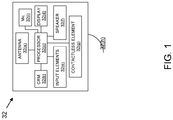
- the portable consumer device may comprise a computer readable medium and a body as shown in FIG. 1.
- FIG. 1 shows a number of components, and the portable consumer devices according to embodiments of the invention may comprise any suitable combination or subset of such components.
- the computer readable medium 32(b) may be present within the body 32(h), or may be detachable from it.
- the body 32(h) may be in the form a plastic substrate, housing, or other structure.
- the computer readable medium 32(b) may be a memory that stores data and may be in any suitable form including a magnetic stripe, a memory chip, etc.
- the memory preferably stores information such as financial information, transit information (e.g., as in a subway or train pass), access information (e.g., as in access badges), etc.
- Financial information may include information such as bank account information, bank identification number (BIN), credit or debit card number information, account balance information, expiration date, consumer information such as name, date of birth, etc. Any of this information may be transmitted by the portable consumer device.
- Information in the memory may also be in the form of data tracks that are traditionally associated with credits cards.
- Such tracks include Track 1 and Track 2.
- Track 1 International Air Transport Association
- Track 2 contains the cardholder's name as well as account number and other discretionary data. This track is sometimes used by the airlines when securing reservations with a credit card.
- Track 2 (“American Banking Association”) is currently most commonly used. This is the track that is read by ATMs and credit card checkers.
- the ABA American Banking Association designed the specifications of this track and all world banks must abide by it. It contains the cardholder's account, encrypted PIN, plus other discretionary data.
- the portable consumer device 32 may further include a contactless element 32(g), which is typically implemented in the form of a semiconductor chip (or other data storage element) with an associated wireless transfer (e.g., data transmission) element, such as an antenna.
- Contactless element 32(g) is associated with (e.g., embedded within) portable consumer device 32 and data or control instructions transmitted via a cellular network may be applied to contactless element 32(g) by means of a contactless element interface (not shown).
- the contactless element interface functions to permit the exchange of data and/or control instructions between the mobile device circuitry (and hence the cellular network) and an optional contactless element 32(g).
- Contactless element 32(g) is capable of transferring and receiving data using a near field communications (“NFC") capability (or near field communications medium) typically in accordance with a standardized protocol or data transfer mechanism (e.g., ISO 14443/NFC).
- NFC near field communications
- Near field communications capability is a short-range communications capability, such as RFID, BluetoothTM, infra-red, or other data transfer capability that can be used to exchange data between the portable consumer device 32 and an interrogation device.
- the portable consumer device 32 is capable of communicating and transferring data and/or control instructions via both cellular network and near field communications capability.
- the portable consumer device 32 may also include a processor 32(c) (e.g., a microprocessor) for processing the functions of the portable consumer device 32 and a display 32(d) to allow a consumer to see phone numbers and other information and messages.
- the portable consumer device 32 may further include input elements 32(e) to allow a consumer to input information into the device, a speaker 32(f) to allow the consumer to hear voice communication, music, etc., and a microphone 32(i) to allow the consumer to transmit her voice through the portable consumer device 32.
- the portable consumer device 32 may also include an antenna 32(a) for wireless data transfer (e.g., data transmission). The antenna 32(a) can be used to couple the wireless interrogation to the portable consumer device 32 as well as transmit a wireless signal from the portable consumer device 32 back to the interrogation device or some other device reader.
- the antenna 32(a) can be coupled to the processor 32(c) and other elements within the portable consumer device directly or via an RF front end (not shown).
- the RF front end can be configured, for example, to provide the air interface between the portable consumer device 32 and remote devices.
- the RF front end may be configured to receive an interrogation signal at RF and filter, downconvert, and demodulate the interrogation signal for further signal processing.
- the RF front end can be configured to receive a data transmission signal from the processor 32(c) and modulate and upconvert the signal or otherwise format the data transmission signal for wireless transmission.
- the portable consumer device 32 may also include one or more power sources or power supplies (not shown).
- a power supply may be coupled to the antenna 32(a) and can be configured to generate power from the interrogation signal received via the antenna 32(a).
- a power supply may be coupled to a battery or some other power source and may generate the power for the various elements of the portable consumer device 32 from the power source.
- the portable consumer device may also optionally have features such as magnetic strips. Such devices can operate in either a contact or contactless mode.
- the portable consumer device of the present invention may be used with authorized interrogation devices (e.g., authorized readers) that may also have antennas and signal generators.
- authorized interrogation devices may be present at point of sale (POS) terminals, ATM (automatic teller machines), and the like.
- POS point of sale
- ATM automated teller machines
- Such interrogation devices may be used to wirelessly read information stored on the portable consumer device memory or to write information onto the same.
- FIG. 2 shows a wireless communication system 100 that illustrates the security issues currently associated with contactless portable consumer devices.
- portable consumer device 32 may be interrogated by an authorized interrogation device 120.
- it can also unfortunately be interrogated by the unauthorized interrogation device 130.
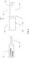
- FIG. 3 is a schematic representation of a contactless portable consumer device 200 in accordance with one embodiment of the present invention.
- a base portion 210 of portable consumer device 200 includes a housing, a processor 212 (e.g., a microprocessor and a memory storing financial information) and a transmitting antenna 214.
- the housing can simply be flat body with or without laminated sheets, or may be a molded plastic body.
- the transmitting antenna 214 may transmit electromagnetic signals to an interrogation device (e.g., contactless reader 120), and it may also receive electromagnetic interrogation signals from the interrogation device.
- an interrogation device e.g., contactless reader 120
- Shield portion 220 of portable consumer device 200 includes an electromagnetic shield 225, which may be formed of a sheet of metal, metal mesh, or a coat of metallic ink, or other suitable electromagnetic shielding material. It is preferred that shield 225 is capable of shielding RF electromagnetic signals or otherwise attenuating or inhibiting the receipt and transmission of signals. For example, the shield 225, when positioned proximate the antenna 214, may operate to electronically load, mismatch, or otherwise de-tune the antenna 214, such that the antenna 214 couples a substantially attenuated version of the interrogation signal to the portable consumer device 200 relative to the case when the shield 225 is positioned proximate to the antenna 214.
- FIG. 3 shows shield 225 in an open position about hinge 215, in which the portable consumer device 200 is capable of communicating with contactless reader 120 via communication link 150 to transmit the information stored in processor 212.
- contactless reader 120 may emit an electromagnetic interrogation field that, when coupled with movement of device 200 through the field, induces current in transmitting antenna 214 for reading processor 212 and transmitting a return signal containing the information stored within processor 212.
- a power source (not shown) of the portable consumer device 200 may power processor 212 and antenna 214 to transmit a signal to contactless reader 120 containing the stored information.
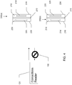
- FIG. 4 shows portable consumer device 200(a) when shield 225 is in a closed position, having swung closed about hinge 215, rendering the device incapable of communicating with contactless reader 120.
- Communication link 150 is broken when front face 226 of the device is disposed toward the contactless reader 120 because shield 225 is disposed between transmitting antenna 214 and the contactless reader 120. It should be understood that communication link 150 remains broken when rear face 216 of the device is disposed toward contactless reader 120 because base portion 210 is also electromagnetically shielded.
- rear face 216 can be electromagnetically shielded by a backing material of the chip.
- a metal sheet/mesh or metallic coating on a plastic body panel of base portion 210 can also be used to provide shielding.
- Shield 225 may be about the same size as or slightly larger than the transmitting antenna 214 and may entirely cover the antenna 214 when it is in the closed position. Alternatively, shield 225 may be sized to substantially cover the entire surface of shield portion 220. Shield 225 is to be formed of a material and in a size that effectively blocks transmitting antenna 214 from transmitting or receiving electromagnetic signals when the shield is in the closed position. Hinge 215 may be configured so as to be bias the shield portion 220 in a closed position and may also enable the shield portion 220 to be held in the open position.
- the antenna 214 may be disposed between the contactless reader 120 and the shield 225.
- the region between the antenna 214 and the reader 120 may be free of a shield.
- the shield 225 may be larger than the antenna 214 (or may be otherwise configured to achieve the same result), so that the shield can act as a ground effectively preventing interrogation via the antenna 214.
- interrogation of the portable consumer device via the antenna 214 can be prevented, regardless of the orientation of the portable consumer device.
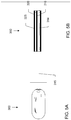
- FIG. 5A and 5B show a portable consumer device 300 in accordance with an example not forming part of the claimed invention in which the portable consumer device is implemented as a hinged key fob.
- Key fob 300 includes a hinge 315 about which the body portions 310 and 320 can be rotated to open or close the key fob.
- Base portion 310 includes a processor (not shown) and transmitting antenna 314 as previously described.
- Shield portion 320 includes or constitutes an electromagnetic shield 325 as previously described for blocking electromagnetic radiation from reaching antenna 314.
- FIG. 6 shows portable consumer device 400 in accordance with another embodiment of the present invention in which the portable consumer device is implemented as a flip-style cell phone.
- Transmitting antenna 414 may be disposed on a base portion 410 of the cell phone 400 and shield 425 may be disposed on a display portion 420 of the cell phone such that when the portions 410 and 420 are closed about hinge 415, the shield 225 effectively blocks antenna 414 from communicating with an interrogation device (not shown).
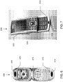
- FIG. 7 shows portable consumer device 500 in accordance with another embodiment of the present invention in which the portable consumer device is implemented as a sliding-style cell phone.
- Transmitting antenna 514 may be disposed on a base portion 510 of the cell phone 500 and shield 525 may be disposed within sliding display portion 520 of the cell phone such that when the portion 520 is slid closed over base 520, the shield 225 effectively blocks antenna 514 from communicating with an interrogation device (not shown).
- any suitable arrangement may be used to move the electromagnetic shield over a transmitting or receiving portion of the portable consumer device to prevent the device from communicating with an interrogation device.
- FIG. 8 is a flow diagram illustrating a method 1000 for providing secure wireless communication with an interrogation device.
- the method may be entered into at step 1010, at which an portable consumer device is provided that includes a memory for storing information, an antenna, and an electromagnetic shield configured to shield the antenna in a closed position.
- a credit card issuer may provide a consumer with a portable consumer device configured for secure contactless communication.
- a consumer is allowed to place the portable consumer device proximate to the interrogation device.
- a consumer may be allowed to place the portable consumer device proximate to an authorized interrogation device at a POS terminal, which may emit an interrogation signal for powering and communicating with the device.
- the portable consumer device is only able to communicate with the interrogation device when the shield is moved to an open position to uncover the antenna. For example, the consumer may flip the shield about a hinge to uncover the antenna.
- a portable consumer device can be made by first forming an antenna on a substrate.
- a memory may be coupled to the antenna.
- the memory may be present in the form of one or more chips which may be mounted (using standard chip mounting processes) on the substrate, so that the one or more chips are electrically coupled to the antenna.
- the substrate may be an insulating plastic substrate like those typically used in a payment card such as a credit card.
- Metal patterns can be formed on the substrate using conventional circuit printing processes.
- An electromagnetic shield material may be added to the substrate to prevent communication between the interrogation device and the antenna through the substrate.
- the movable shield may be attached to the substrate with a suitable mechanism, such as a hinge, for enabling the shield to be moved from a closed position covering the antenna and an open position that enables communication with the interrogation device.
- Embodiments of the invention have a number of advantages.
- a consumer opens the shield of the portable consumer device to expose the transmitting portion, the consumer makes a conscious decision to allow the portable consumer device to be interrogated.
- the portable consumer device cannot be successfully interrogated when the shield is in its default, closed position. Accordingly, information in the portable consumer device can be retrieved when the consumer wants it to be transmitted, but cannot be retrieved when the consumer does not want the information to be transmitted.
- embodiments of the invention are relatively easy to manufacture.
- embodiments of the invention are relatively inexpensive to manufacture and are effective in preventing unauthorized interrogation of a portable consumer device.
- embodiments of the invention are simple to use, making it more likely that a consumer will use it.
- embodiments of the invention can prevent wireless interrogation, regardless of the orientation of the portable consumer device. Embodiments of the invention may satisfy all or any suitable combination of such advantages.
Applications Claiming Priority (2)
| Application Number | Priority Date | Filing Date | Title |
|---|---|---|---|
| US11/811,875 US8604995B2 (en) | 2007-06-11 | 2007-06-11 | Shielding of portable consumer device |
| PCT/US2008/065081 WO2008154165A1 (en) | 2007-06-11 | 2008-05-29 | Shielding of portable consumer device |
Publications (3)
| Publication Number | Publication Date |
|---|---|
| EP2160708A1 EP2160708A1 (en) | 2010-03-10 |
| EP2160708A4 EP2160708A4 (en) | 2011-12-07 |
| EP2160708B1 true EP2160708B1 (en) | 2020-01-01 |
Family
ID=40095343
Family Applications (1)
| Application Number | Title | Priority Date | Filing Date |
|---|---|---|---|
| EP08769787.6A Active EP2160708B1 (en) | 2007-06-11 | 2008-05-29 | Shielding of portable consumer device |
Country Status (7)
| Country | Link |
|---|---|
| US (1) | US8604995B2 (ko) |
| EP (1) | EP2160708B1 (ko) |
| JP (2) | JP2010529576A (ko) |
| KR (1) | KR20100041759A (ko) |
| CN (1) | CN101743557B (ko) |
| CA (1) | CA2691142A1 (ko) |
| WO (1) | WO2008154165A1 (ko) |
Families Citing this family (48)
| Publication number | Priority date | Publication date | Assignee | Title |
|---|---|---|---|---|
| US7761374B2 (en) | 2003-08-18 | 2010-07-20 | Visa International Service Association | Method and system for generating a dynamic verification value |
| US7740168B2 (en) | 2003-08-18 | 2010-06-22 | Visa U.S.A. Inc. | Method and system for generating a dynamic verification value |
| US8102243B2 (en) | 2005-10-31 | 2012-01-24 | Curio Ltd. | RFID protection device, and related methods |
| US7889056B2 (en) * | 2005-10-31 | 2011-02-15 | Curio, Ltd. | RFID protection system, device, combination, and related methods |
| US9065643B2 (en) | 2006-04-05 | 2015-06-23 | Visa U.S.A. Inc. | System and method for account identifier obfuscation |
| US7818264B2 (en) | 2006-06-19 | 2010-10-19 | Visa U.S.A. Inc. | Track data encryption |
| US8505826B2 (en) | 2007-04-16 | 2013-08-13 | Visa U.S.A. | Anti-interrogation for portable device |
| US20090112767A1 (en) | 2007-10-25 | 2009-04-30 | Ayman Hammad | Escrow system and method |
| US8038068B2 (en) | 2007-11-28 | 2011-10-18 | Visa U.S.A. Inc. | Multifunction removable cover for portable payment device |
| US8707319B2 (en) * | 2008-06-26 | 2014-04-22 | Visa International Service Association | Resource location verification by comparing and updating resource location with a location of a consumer device after a threshold of location mismatches is exceeded |
| US8833664B2 (en) * | 2009-12-18 | 2014-09-16 | Yu Yung Choi | Enhanced performance and security RFID device |
| IT1401521B1 (it) * | 2010-08-11 | 2013-07-26 | St Microelectronics Srl | Sistema di sicurezza per almeno un circuito integrato ic, scheda a circuito integrato in sicurezza e metodo di comunicazione wireless in sicurezza. |
| US8469281B2 (en) * | 2010-09-07 | 2013-06-25 | Identive Group, Inc. | RFID label with shielding element |
| TWI446271B (zh) * | 2010-09-14 | 2014-07-21 | Icon Minsky Luo | 近場通訊可讀取裝置、使用此裝置的驗證系統及其方法 |
| GB2487927B (en) * | 2011-02-08 | 2016-05-04 | William Clarke Stephen | Indicator device |
| US20130013490A1 (en) * | 2011-07-08 | 2013-01-10 | Bank Of America Corporation | Mobile apparatus with back-up payment system |
| US20130080238A1 (en) * | 2011-09-22 | 2013-03-28 | Bryan Kelly | Method and System for Operating a Customer or Player Loyalty System Including a Portable Device Such as a Smartcard |
| JP2013073291A (ja) * | 2011-09-27 | 2013-04-22 | Nec Saitama Ltd | 非接触通信端末、非接触通信制限方法及びプログラム |
| US8763913B2 (en) * | 2011-10-25 | 2014-07-01 | International Business Machines Corporation | RFID tag integrated into an enclosure surface door |
| US9722460B2 (en) * | 2011-12-21 | 2017-08-01 | Intel Corporation | Coil and ferrite configuration to facilitate near field coupling |
| EP2717552A1 (en) * | 2012-10-04 | 2014-04-09 | Nagravision S.A. | A portable proximity wireless communication device |
| TWI528639B (zh) * | 2012-10-09 | 2016-04-01 | 啟碁科技股份有限公司 | 天線裝置及無線通訊裝置 |
| DE102012110532B4 (de) * | 2012-11-05 | 2019-04-04 | Infineon Technologies Ag | Chipkarte zum kontaktlosen Durchführen eines Autorisierungs- und/oder Bezahlvorgangs, Verfahren zum Betreiben einer Chipkarte und Verfahren zum Herstellen einer Chipkarte |
| US8948694B2 (en) | 2012-12-04 | 2015-02-03 | Blackberry Limited | Antenna shield for proximity-based communication devices |
| EP2741247B1 (en) * | 2012-12-04 | 2017-02-15 | BlackBerry Limited | Antenna shield for proximity-based communication devices |
| EP2987119A1 (en) | 2013-04-19 | 2016-02-24 | Curio, Ltd | Rfid disruption device and related methods |
| AT515401B1 (de) * | 2014-02-03 | 2016-04-15 | Seibersdorf Labor Gmbh | Abschirmelement zum Anbringen auf einem Gegenstand |
| US9345050B2 (en) * | 2014-02-21 | 2016-05-17 | Sony Corporation | NFC collision avoidance with controllable NFC transmission delay timing |
| US9312921B2 (en) | 2014-02-21 | 2016-04-12 | Sony Corporation | Retrieving/authorizing content on user equipment based on information from connectable accessory with NFC circuit |
| US9408238B2 (en) * | 2014-02-21 | 2016-08-02 | Sony Corporation | Removable conductive layer that shields and/or shorts nodes of an NFC circuit to control transmissions therefrom |
| KR20160002070A (ko) * | 2014-06-30 | 2016-01-07 | 엘지이노텍 주식회사 | 케이스 장치 |
| DE102014112287A1 (de) * | 2014-08-27 | 2016-03-03 | Bundesdruckerei Gmbh | Kommunikationsvorrichtung |
| US9633239B2 (en) * | 2015-09-24 | 2017-04-25 | Advanced Digital Broadcast S.A. | System and method for selective access to RFID functionality |
| US9990574B2 (en) * | 2015-11-27 | 2018-06-05 | Joseph James Strong | Holder for RFID enabled cards |
| WO2017146572A1 (en) * | 2016-02-23 | 2017-08-31 | R.J. Van Geer Beheer Bv | Holder for cards or keys having recharge means for onboard electronics |
| US10181652B2 (en) * | 2016-08-16 | 2019-01-15 | Think Wireless Inc. | Antenna desensitization system and design method thereof |
| US20180324986A1 (en) * | 2017-05-03 | 2018-11-08 | Tsvetana Yvanova | Hi Performance Security Folio for Digital Mobile Devices |
| CN108064076B (zh) * | 2017-12-07 | 2021-04-27 | Oppo广东移动通信有限公司 | 发射功率的控制方法、装置及存储介质和移动终端 |
| US10951414B2 (en) * | 2018-01-29 | 2021-03-16 | Hub data security Ltd. | Method for securing digital currency |
| US10878686B1 (en) * | 2018-03-26 | 2020-12-29 | Badge Messenger Inc. | Badge holder with one touch communication |
| FR3081243B1 (fr) * | 2018-05-18 | 2020-05-08 | Smart Packaging Solutions | Passeport electronique securise contre les lectures non autorisees |
| CN108537313A (zh) * | 2018-07-23 | 2018-09-14 | 无锡恒烨软件技术有限公司 | 一种仓库出库扫描系统 |
| CN109147071B (zh) * | 2018-09-18 | 2020-08-04 | 厦门安胜网络科技有限公司 | 一种用于保护etc的装置及方法 |
| US10949725B1 (en) | 2019-10-03 | 2021-03-16 | Popl Co. | Method and device for sharing social media profile |
| KR20210042202A (ko) * | 2019-10-08 | 2021-04-19 | 삼성디스플레이 주식회사 | 표시 장치 |
| US11403472B2 (en) * | 2019-11-04 | 2022-08-02 | Edgar Davin Salatandre | Apparatus for use with a NFC tag reader |
| CN111010470B (zh) * | 2019-12-10 | 2021-09-03 | 惠州Tcl移动通信有限公司 | 一种天线调谐方法、装置及存储介质 |
| US11208839B2 (en) * | 2020-03-03 | 2021-12-28 | Gmi Holdings, Inc. | Space venting upward acting door system and method |
Family Cites Families (120)
| Publication number | Priority date | Publication date | Assignee | Title |
|---|---|---|---|---|
| US4480250A (en) | 1981-11-27 | 1984-10-30 | Mcneely Charles D | Credit card carrier with alarm |
| KR920001502Y1 (ko) | 1989-11-22 | 1992-03-05 | 오광진 | 신용카드의 안전케이스 |
| US5090563A (en) | 1990-02-05 | 1992-02-25 | Conductive Containers, Inc. | Electro-static protective container for electrical components |
| GB9010778D0 (en) | 1990-05-14 | 1990-07-04 | Godfrey Richard L | Cardholders incorporating keepers |
| US5051724A (en) | 1990-05-31 | 1991-09-24 | Carl R. Morrow | Key security device |
| JPH0464176U (ko) * | 1990-10-11 | 1992-06-01 | ||
| US5090583A (en) | 1991-03-27 | 1992-02-25 | Magenta Corporation | Tamper-evident, tamper-resistant closure |
| JPH0572330A (ja) * | 1991-09-12 | 1993-03-26 | Fuji Electric Co Ltd | 個体識別装置 |
| JPH05254284A (ja) * | 1992-03-13 | 1993-10-05 | Fujitsu Ltd | 複合icカード |
| US6045652A (en) | 1992-06-17 | 2000-04-04 | Micron Communications, Inc. | Method of manufacturing an enclosed transceiver |
| US5275285A (en) | 1992-12-30 | 1994-01-04 | Clegg Industries | Business card holder with sound generating microchip |
| US5335366A (en) | 1993-02-01 | 1994-08-02 | Daniels John J | Radiation shielding apparatus for a radio transmitting device |
| US5477038A (en) | 1993-10-25 | 1995-12-19 | Visa International | Method and apparatus for distributing currency |
| US5465206B1 (en) | 1993-11-01 | 1998-04-21 | Visa Int Service Ass | Electronic bill pay system |
| US6457647B1 (en) | 1993-11-16 | 2002-10-01 | Canon Kabushiki Kaisha | Memory card adaptor to facilitate upgrades and the like |
| US5515031A (en) | 1994-03-28 | 1996-05-07 | Pereira; Neil H. | Credit card detector and validator |
| US5500513A (en) | 1994-05-11 | 1996-03-19 | Visa International | Automated purchasing control system |
| US5594200A (en) | 1995-06-09 | 1997-01-14 | Ramsey Electronics, Inc. | Electromagnetic isolation chamber |
| US5790677A (en) | 1995-06-29 | 1998-08-04 | Microsoft Corporation | System and method for secure electronic commerce transactions |
| EP0822513A3 (en) | 1996-08-01 | 1998-08-05 | Eastman Kodak Company | Magnetically encodable card having improved security features |
| US6247129B1 (en) | 1997-03-12 | 2001-06-12 | Visa International Service Association | Secure electronic commerce employing integrated circuit cards |
| JPH1125242A (ja) * | 1997-07-01 | 1999-01-29 | Dainippon Printing Co Ltd | 非接触icカード封入体及び非接触icカード |
| JPH1175329A (ja) * | 1997-08-29 | 1999-03-16 | Hitachi Ltd | 非接触icカードシステム |
| US5941375A (en) | 1997-12-22 | 1999-08-24 | Kamens, L.L.C. | Device for protecting magnetic cards and method of making same |
| US6121544A (en) * | 1998-01-15 | 2000-09-19 | Petsinger; Julie Ann | Electromagnetic shield to prevent surreptitious access to contactless smartcards |
| US6608561B2 (en) | 1998-05-19 | 2003-08-19 | Meat Processing Service Corp., Inc. | Method for making a radio frequency identification device |
| US6154137A (en) | 1998-06-08 | 2000-11-28 | 3M Innovative Properties Company | Identification tag with enhanced security |
| JP4541465B2 (ja) | 1998-09-10 | 2010-09-08 | ミルストーン トランスファー エージー、エル.エル.シー. | 電子タグ、電子タグ識別システム |
| US6502135B1 (en) | 1998-10-30 | 2002-12-31 | Science Applications International Corporation | Agile network protocol for secure communications with assured system availability |
| US7188180B2 (en) | 1998-10-30 | 2007-03-06 | Vimetx, Inc. | Method for establishing secure communication link between computers of virtual private network |
| US6079621A (en) | 1998-11-13 | 2000-06-27 | Chrysalis-Its Inc. | Secure card for E-commerce and identification |
| US6127938A (en) | 1999-02-12 | 2000-10-03 | Privacy Shield L.L.C. | Adjustable shield for vehicle mounted toll collection identifier |
| US6603981B1 (en) | 1999-07-06 | 2003-08-05 | Juan C. Carillo, Jr. | Device for radiation shielding of wireless transmit/receive electronic equipment such as cellular telephone from close proximity direct line-of-sight electromagnetic fields |
| US7340439B2 (en) | 1999-09-28 | 2008-03-04 | Chameleon Network Inc. | Portable electronic authorization system and method |
| US6859831B1 (en) | 1999-10-06 | 2005-02-22 | Sensoria Corporation | Method and apparatus for internetworked wireless integrated network sensor (WINS) nodes |
| TW502286B (en) | 1999-12-09 | 2002-09-11 | Koninkl Philips Electronics Nv | Semiconductor device comprising a security coating and smartcard provided with such a device |
| JP5095900B2 (ja) | 2000-04-26 | 2012-12-12 | バーネットエックス インコーポレーティッド | 保証されたシステム可用性を有する安全通信用のアジル・ネットワーク・プロトコルの改良 |
| US6359216B1 (en) | 2000-06-29 | 2002-03-19 | Chi-Yun Liu | Electromagnetic wave shield pad for mobile phone |
| CN101025778A (zh) | 2000-07-25 | 2007-08-29 | 有限会社信息安全 | 保密信息记录媒介、保护方法、保护存储方法及信息访问报警系统 |
| US6588660B1 (en) | 2000-09-29 | 2003-07-08 | Hewlett-Packard Development Company, L.P. | Passive contactless smartcard security system |
| US20020046351A1 (en) | 2000-09-29 | 2002-04-18 | Keisuke Takemori | Intrusion preventing system |
| US6400270B1 (en) | 2000-11-02 | 2002-06-04 | Robert Person | Wallet protection system |
| JP2002198850A (ja) | 2000-12-27 | 2002-07-12 | Sony Corp | 携帯電話機 |
| US7809650B2 (en) | 2003-07-01 | 2010-10-05 | Visa U.S.A. Inc. | Method and system for providing risk information in connection with transaction processing |
| US20020137473A1 (en) | 2001-03-12 | 2002-09-26 | Jenkins Deborah L. | Radiation shield for cellular telephones |
| EP1249888A3 (en) | 2001-04-11 | 2004-01-07 | Lg Electronics Inc. | Internal display-mounted antenna for mobile electronic equipment and mobile electronic equipment incorporating same |
| US6816058B2 (en) | 2001-04-26 | 2004-11-09 | Mcgregor Christopher M | Bio-metric smart card, bio-metric smart card reader and method of use |
| US7243853B1 (en) | 2001-12-04 | 2007-07-17 | Visa U.S.A. Inc. | Method and system for facilitating memory and application management on a secured token |
| JP2003324765A (ja) | 2002-05-08 | 2003-11-14 | Nec Infrontia Corp | 位置情報端末のオン/オフ制御装置 |
| JP4170981B2 (ja) | 2002-05-24 | 2008-10-22 | 株式会社エヌ・ティ・ティ・ドコモ | 下位互換性がある小型化されたチップカードおよび小型化されたチップカード用アダプタ |
| US7356516B2 (en) | 2002-06-13 | 2008-04-08 | Visa U.S.A. Inc. | Method and system for facilitating electronic dispute resolution |
| US20040019522A1 (en) | 2002-07-26 | 2004-01-29 | Visa U.S.A., Inc. | Multi-application smart card device software solution integrating sales tax, payment and discount rewards |
| US7784684B2 (en) | 2002-08-08 | 2010-08-31 | Fujitsu Limited | Wireless computer wallet for physical point of sale (POS) transactions |
| US7280981B2 (en) | 2002-08-27 | 2007-10-09 | Visa U.S.A. Inc. | Method and system for facilitating payment transactions using access devices |
| US8626577B2 (en) | 2002-09-13 | 2014-01-07 | Visa U.S.A | Network centric loyalty system |
| US6837425B2 (en) | 2002-09-13 | 2005-01-04 | Visa U.S.A. Inc. | Compact protocol and solution for substantially offline messaging between portable consumer device and based device |
| US7121456B2 (en) | 2002-09-13 | 2006-10-17 | Visa U.S.A. Inc. | Method and system for managing token image replacement |
| US8015060B2 (en) | 2002-09-13 | 2011-09-06 | Visa Usa, Inc. | Method and system for managing limited use coupon and coupon prioritization |
| US20040148224A1 (en) | 2002-09-13 | 2004-07-29 | Visa U.S.A. | Method and apparatus for electronic support and delivery of multiple lottery and sweepstake programs, in substantially off-line environments |
| US9852437B2 (en) | 2002-09-13 | 2017-12-26 | Visa U.S.A. Inc. | Opt-in/opt-out in loyalty system |
| EP1547030A2 (en) | 2002-10-02 | 2005-06-29 | Discover Financial Services, Inc. | Multi-function credit card and case |
| US20040139021A1 (en) | 2002-10-07 | 2004-07-15 | Visa International Service Association | Method and system for facilitating data access and management on a secure token |
| US6920611B1 (en) | 2002-11-25 | 2005-07-19 | Visa U.S.A., Inc. | Method and system for implementing a loyalty merchant component |
| JP2004227046A (ja) * | 2003-01-20 | 2004-08-12 | Hitachi Ltd | 携帯情報機器 |
| US7702916B2 (en) | 2003-03-31 | 2010-04-20 | Visa U.S.A. Inc. | Method and system for secure authentication |
| US6845863B1 (en) | 2003-04-22 | 2005-01-25 | Herman Riley | Card magnetic strip protector sleeve |
| WO2005006111A2 (en) | 2003-04-29 | 2005-01-20 | Visa U. S. A. Inc. | Method and system for facilitating switching of financial institution accounts |
| US7827077B2 (en) | 2003-05-02 | 2010-11-02 | Visa U.S.A. Inc. | Method and apparatus for management of electronic receipts on portable devices |
| US6970070B2 (en) | 2003-05-08 | 2005-11-29 | Rsa Security Inc. | Method and apparatus for selective blocking of radio frequency identification devices |
| EP1629419A1 (en) | 2003-05-20 | 2006-03-01 | Philips Intellectual Property & Standards GmbH | Electronic communications system |
| EP1644861A4 (en) | 2003-07-02 | 2009-05-13 | Visa Int Service Ass | MANAGEMENT OF CARD HOLDER ACTIVATION IN A SECURE AUTHENTICATION PROGRAM |
| KR100652620B1 (ko) | 2003-07-30 | 2006-12-06 | 엘지전자 주식회사 | 내장형 안테나가 구비된 휴대용 단말기 |
| US7104446B2 (en) | 2003-09-03 | 2006-09-12 | Visa U.S.A., Inc. | Method, system and portable consumer device using wildcard values |
| US7051923B2 (en) | 2003-09-12 | 2006-05-30 | Visa U.S.A., Inc. | Method and system for providing interactive cardholder rewards image replacement |
| TWI249875B (en) | 2003-09-19 | 2006-02-21 | Univ Nat Taiwan Science Tech | Method and apparatus for improving antenna radiation patterns |
| US8407083B2 (en) | 2003-09-30 | 2013-03-26 | Visa U.S.A., Inc. | Method and system for managing reward reversal after posting |
| US20050071226A1 (en) | 2003-09-30 | 2005-03-31 | Visa U.S.A. Inc. | Method and system for managing dynamic terms and conditions and user interaction |
| US8260661B2 (en) | 2003-09-30 | 2012-09-04 | Visa U.S.A. Inc. | System and apparatus for linking multiple rewards programs to promote the purchase of specific product mixes |
| US20050071227A1 (en) | 2003-09-30 | 2005-03-31 | Visa U.S.A. | Method and system for managing concurrent sku-based rewards program |
| US8005763B2 (en) | 2003-09-30 | 2011-08-23 | Visa U.S.A. Inc. | Method and system for providing a distributed adaptive rules based dynamic pricing system |
| US7039611B2 (en) | 2003-11-06 | 2006-05-02 | Visa U.S.A., Inc. | Managing attempts to initiate authentication of electronic commerce card transactions |
| US7653602B2 (en) | 2003-11-06 | 2010-01-26 | Visa U.S.A. Inc. | Centralized electronic commerce card transactions |
| US7762470B2 (en) | 2003-11-17 | 2010-07-27 | Dpd Patent Trust Ltd. | RFID token with multiple interface controller |
| US7187959B2 (en) | 2003-11-25 | 2007-03-06 | Motorola, Inc. | Antenna structure for devices with conductive chassis |
| JP2005293191A (ja) | 2004-03-31 | 2005-10-20 | Kyocera Corp | 電子機器 |
| US20060005050A1 (en) | 2004-06-10 | 2006-01-05 | Supercom Ltd. | Tamper-free and forgery-proof passport and methods for providing same |
| ES2373029T3 (es) | 2004-06-16 | 2012-01-30 | Gemalto Sa | Documento electrónico blindado sin contacto. |
| US8571978B2 (en) | 2004-06-17 | 2013-10-29 | Visa International Service Association | Method and system for providing assurance and financing services |
| US7375631B2 (en) * | 2004-07-26 | 2008-05-20 | Lenovo (Singapore) Pte. Ltd. | Enabling and disabling a wireless RFID portable transponder |
| US20060044206A1 (en) | 2004-08-27 | 2006-03-02 | Moskowitz Paul A | Shielding wireless transponders |
| US7958030B2 (en) | 2004-09-01 | 2011-06-07 | Visa U.S.A. Inc. | System and method for issuer originated payments for on-line banking bill payments |
| US7163152B2 (en) | 2004-12-15 | 2007-01-16 | Osborn Warren R | Protective container for readable cards |
| US7086587B2 (en) | 2004-12-16 | 2006-08-08 | International Business Machines Corporation | Anti-tracking system to ensure consumer privacy |
| US7711639B2 (en) | 2005-01-12 | 2010-05-04 | Visa International | Pre-funding system and method |
| US20060178957A1 (en) | 2005-01-18 | 2006-08-10 | Visa U.S.A. | Commercial market determination and forecasting system and method |
| US7124937B2 (en) | 2005-01-21 | 2006-10-24 | Visa U.S.A. Inc. | Wireless payment methods and systems |
| US20060187060A1 (en) * | 2005-02-07 | 2006-08-24 | Colby Steven M | Identity devices including radio frequency shielding |
| JP4374000B2 (ja) | 2005-02-23 | 2009-11-25 | 株式会社大洋 | Rfid用スキミング防止機能を備えたカードホルダ |
| US20060254815A1 (en) | 2005-04-26 | 2006-11-16 | Humphrey Thomas W | Radiofrequency identification shielding |
| JP3113025U (ja) | 2005-05-09 | 2005-09-02 | 綾乃 村上 | セキュリティー機能付icカード内蔵型携帯電話 |
| JP2006313482A (ja) | 2005-05-09 | 2006-11-16 | Toshiba Elevator Co Ltd | 電磁波遮蔽体及び電磁波遮蔽方法 |
| US7571752B1 (en) | 2005-06-20 | 2009-08-11 | Joseph Kudla | Security wallet insert for thwarting loss of credit cards |
| JP2007006029A (ja) * | 2005-06-22 | 2007-01-11 | Sony Corp | Rfid内蔵電子機器 |
| US7522905B2 (en) | 2005-06-24 | 2009-04-21 | Visa U.S.A. Inc. | Apparatus and method for preventing wireless interrogation of portable consumer devices |
| US7482925B2 (en) * | 2005-06-24 | 2009-01-27 | Visa U.S.A. | Apparatus and method to electromagnetically shield portable consumer devices |
| US7694287B2 (en) | 2005-06-29 | 2010-04-06 | Visa U.S.A. | Schema-based dynamic parse/build engine for parsing multi-format messages |
| US7774402B2 (en) | 2005-06-29 | 2010-08-10 | Visa U.S.A. | Adaptive gateway for switching transactions and data on unreliable networks using context-based rules |
| US8762263B2 (en) | 2005-09-06 | 2014-06-24 | Visa U.S.A. Inc. | System and method for secured account numbers in proximity devices |
| US20070055597A1 (en) | 2005-09-08 | 2007-03-08 | Visa U.S.A. | Method and system for manipulating purchase information |
| US20070083465A1 (en) | 2005-10-07 | 2007-04-12 | Visa U.S.A., Inc. | Method and system using bill payment reminders |
| JP2007108982A (ja) | 2005-10-13 | 2007-04-26 | Nec Corp | Icカードホルダー |
| US7844490B2 (en) | 2005-11-02 | 2010-11-30 | Visa U.S.A. Inc. | Method and system for conducting promotional programs |
| US20070109130A1 (en) * | 2005-11-17 | 2007-05-17 | Edenfield Benjamin W | Card cases and wallets with radio frequency shielding |
| US7886969B2 (en) | 2005-12-06 | 2011-02-15 | Visa U.S.A. Inc. | Method and system for loading and reloading portable consumer devices |
| JP3119493U (ja) * | 2005-12-06 | 2006-03-02 | 株式会社パコム | スキミング防止カード |
| DE102005061688A1 (de) | 2005-12-21 | 2007-07-05 | Stocko Contact Gmbh & Co. Kg | Kontaktiereinheit |
| US7635089B2 (en) * | 2006-07-03 | 2009-12-22 | Identity Stronghold, Llc | Device for shielding reading of a contactless smartcard |
| US20090069049A1 (en) | 2007-09-12 | 2009-03-12 | Devicefidelity, Inc. | Interfacing transaction cards with host devices |
| US20090134223A1 (en) | 2007-11-15 | 2009-05-28 | Richard Peter Matthews | Card Holder-Reader for Wallet Sized Cards |
| US20100219099A1 (en) | 2009-02-12 | 2010-09-02 | Schmitt Stephen E | Secure package for multiple transaction cards |
-
2007
- 2007-06-11 US US11/811,875 patent/US8604995B2/en active Active
-
2008
- 2008-05-29 JP JP2010512251A patent/JP2010529576A/ja active Pending
- 2008-05-29 CN CN200880024860.1A patent/CN101743557B/zh not_active Expired - Fee Related
- 2008-05-29 EP EP08769787.6A patent/EP2160708B1/en active Active
- 2008-05-29 KR KR1020107000387A patent/KR20100041759A/ko not_active Application Discontinuation
- 2008-05-29 CA CA2691142A patent/CA2691142A1/en not_active Abandoned
- 2008-05-29 WO PCT/US2008/065081 patent/WO2008154165A1/en active Application Filing
-
2014
- 2014-04-21 JP JP2014087332A patent/JP2014157618A/ja active Pending
Non-Patent Citations (1)
| Title |
|---|
| None * |
Also Published As
| Publication number | Publication date |
|---|---|
| CN101743557B (zh) | 2014-10-15 |
| JP2010529576A (ja) | 2010-08-26 |
| CN101743557A (zh) | 2010-06-16 |
| JP2014157618A (ja) | 2014-08-28 |
| US8604995B2 (en) | 2013-12-10 |
| KR20100041759A (ko) | 2010-04-22 |
| CA2691142A1 (en) | 2008-12-18 |
| US20080303632A1 (en) | 2008-12-11 |
| WO2008154165A1 (en) | 2008-12-18 |
| EP2160708A4 (en) | 2011-12-07 |
| EP2160708A1 (en) | 2010-03-10 |
Similar Documents
| Publication | Publication Date | Title |
|---|---|---|
| EP2160708B1 (en) | Shielding of portable consumer device | |
| CA2684625C (en) | Anti-interrogation for portable device | |
| US9704087B2 (en) | Apparatus and method to electromagnetically shield portable consumer devices | |
| JP4158483B2 (ja) | Icモジュール | |
| US20070040030A1 (en) | Contactless proximity communications apparatus and method | |
| CN101184410A (zh) | 射频代币的携带装置 | |
| US20150077229A1 (en) | Wireless Device Security System | |
| US11687741B1 (en) | Methods of using a cellular telephone | |
| JP2005032113A (ja) | カードホルダー | |
| US10755157B2 (en) | Advance alert system against copy of contact-less card information | |
| US20240160867A1 (en) | Cellular Telephone Including Biometric Control of Transactions | |
| US20240104329A1 (en) | Assembly for shielding at least one radio-frequency chip and method for making the same | |
| KR20180093309A (ko) | Rf카드 활성화 장치 | |
| JP2005346549A (ja) | 非接触icカード通信防止装置及び非接触icカードケース | |
| KR20090001892U (ko) | 스마트카드 해킹방지 지갑 | |
| JP2017520040A (ja) | 電磁波を通じた非接触データ送信中のデータ盗難、身元詐称、および詐欺を防止するための装置 |
Legal Events
| Date | Code | Title | Description |
|---|---|---|---|
| PUAI | Public reference made under article 153(3) epc to a published international application that has entered the european phase |
Free format text: ORIGINAL CODE: 0009012 |
|
| 17P | Request for examination filed |
Effective date: 20100111 |
|
| AK | Designated contracting states |
Kind code of ref document: A1 Designated state(s): AT BE BG CH CY CZ DE DK EE ES FI FR GB GR HR HU IE IS IT LI LT LU LV MC MT NL NO PL PT RO SE SI SK TR |
|
| AX | Request for extension of the european patent |
Extension state: AL BA MK RS |
|
| RIN1 | Information on inventor provided before grant (corrected) |
Inventor name: HAMMAD, AYMAN |
|
| DAX | Request for extension of the european patent (deleted) | ||
| A4 | Supplementary search report drawn up and despatched |
Effective date: 20111104 |
|
| RIC1 | Information provided on ipc code assigned before grant |
Ipc: G06K 19/07 20060101ALI20111028BHEP Ipc: G06K 17/00 20060101AFI20111028BHEP |
|
| 17Q | First examination report despatched |
Effective date: 20130222 |
|
| STAA | Information on the status of an ep patent application or granted ep patent |
Free format text: STATUS: EXAMINATION IS IN PROGRESS |
|
| GRAP | Despatch of communication of intention to grant a patent |
Free format text: ORIGINAL CODE: EPIDOSNIGR1 |
|
| STAA | Information on the status of an ep patent application or granted ep patent |
Free format text: STATUS: GRANT OF PATENT IS INTENDED |
|
| INTG | Intention to grant announced |
Effective date: 20190731 |
|
| GRAS | Grant fee paid |
Free format text: ORIGINAL CODE: EPIDOSNIGR3 |
|
| GRAA | (expected) grant |
Free format text: ORIGINAL CODE: 0009210 |
|
| STAA | Information on the status of an ep patent application or granted ep patent |
Free format text: STATUS: THE PATENT HAS BEEN GRANTED |
|
| AK | Designated contracting states |
Kind code of ref document: B1 Designated state(s): AT BE BG CH CY CZ DE DK EE ES FI FR GB GR HR HU IE IS IT LI LT LU LV MC MT NL NO PL PT RO SE SI SK TR |
|
| REG | Reference to a national code |
Ref country code: GB Ref legal event code: FG4D |
|
| REG | Reference to a national code |
Ref country code: AT Ref legal event code: REF Ref document number: 1220729 Country of ref document: AT Kind code of ref document: T Effective date: 20200115 Ref country code: CH Ref legal event code: EP |
|
| REG | Reference to a national code |
Ref country code: IE Ref legal event code: FG4D |
|
| REG | Reference to a national code |
Ref country code: DE Ref legal event code: R096 Ref document number: 602008061934 Country of ref document: DE |
|
| REG | Reference to a national code |
Ref country code: NL Ref legal event code: MP Effective date: 20200101 |
|
| REG | Reference to a national code |
Ref country code: LT Ref legal event code: MG4D |
|
| PG25 | Lapsed in a contracting state [announced via postgrant information from national office to epo] |
Ref country code: FI Free format text: LAPSE BECAUSE OF FAILURE TO SUBMIT A TRANSLATION OF THE DESCRIPTION OR TO PAY THE FEE WITHIN THE PRESCRIBED TIME-LIMIT Effective date: 20200101 Ref country code: NO Free format text: LAPSE BECAUSE OF FAILURE TO SUBMIT A TRANSLATION OF THE DESCRIPTION OR TO PAY THE FEE WITHIN THE PRESCRIBED TIME-LIMIT Effective date: 20200401 Ref country code: NL Free format text: LAPSE BECAUSE OF FAILURE TO SUBMIT A TRANSLATION OF THE DESCRIPTION OR TO PAY THE FEE WITHIN THE PRESCRIBED TIME-LIMIT Effective date: 20200101 Ref country code: CZ Free format text: LAPSE BECAUSE OF FAILURE TO SUBMIT A TRANSLATION OF THE DESCRIPTION OR TO PAY THE FEE WITHIN THE PRESCRIBED TIME-LIMIT Effective date: 20200101 Ref country code: LT Free format text: LAPSE BECAUSE OF FAILURE TO SUBMIT A TRANSLATION OF THE DESCRIPTION OR TO PAY THE FEE WITHIN THE PRESCRIBED TIME-LIMIT Effective date: 20200101 Ref country code: PT Free format text: LAPSE BECAUSE OF FAILURE TO SUBMIT A TRANSLATION OF THE DESCRIPTION OR TO PAY THE FEE WITHIN THE PRESCRIBED TIME-LIMIT Effective date: 20200527 |
|
| PGFP | Annual fee paid to national office [announced via postgrant information from national office to epo] |
Ref country code: FR Payment date: 20200422 Year of fee payment: 13 Ref country code: DE Payment date: 20200421 Year of fee payment: 13 |
|
| PG25 | Lapsed in a contracting state [announced via postgrant information from national office to epo] |
Ref country code: SE Free format text: LAPSE BECAUSE OF FAILURE TO SUBMIT A TRANSLATION OF THE DESCRIPTION OR TO PAY THE FEE WITHIN THE PRESCRIBED TIME-LIMIT Effective date: 20200101 Ref country code: IS Free format text: LAPSE BECAUSE OF FAILURE TO SUBMIT A TRANSLATION OF THE DESCRIPTION OR TO PAY THE FEE WITHIN THE PRESCRIBED TIME-LIMIT Effective date: 20200501 Ref country code: HR Free format text: LAPSE BECAUSE OF FAILURE TO SUBMIT A TRANSLATION OF THE DESCRIPTION OR TO PAY THE FEE WITHIN THE PRESCRIBED TIME-LIMIT Effective date: 20200101 Ref country code: LV Free format text: LAPSE BECAUSE OF FAILURE TO SUBMIT A TRANSLATION OF THE DESCRIPTION OR TO PAY THE FEE WITHIN THE PRESCRIBED TIME-LIMIT Effective date: 20200101 Ref country code: GR Free format text: LAPSE BECAUSE OF FAILURE TO SUBMIT A TRANSLATION OF THE DESCRIPTION OR TO PAY THE FEE WITHIN THE PRESCRIBED TIME-LIMIT Effective date: 20200402 Ref country code: BG Free format text: LAPSE BECAUSE OF FAILURE TO SUBMIT A TRANSLATION OF THE DESCRIPTION OR TO PAY THE FEE WITHIN THE PRESCRIBED TIME-LIMIT Effective date: 20200401 |
|
| PGFP | Annual fee paid to national office [announced via postgrant information from national office to epo] |
Ref country code: GB Payment date: 20200423 Year of fee payment: 13 |
|
| REG | Reference to a national code |
Ref country code: DE Ref legal event code: R097 Ref document number: 602008061934 Country of ref document: DE |
|
| PG25 | Lapsed in a contracting state [announced via postgrant information from national office to epo] |
Ref country code: RO Free format text: LAPSE BECAUSE OF FAILURE TO SUBMIT A TRANSLATION OF THE DESCRIPTION OR TO PAY THE FEE WITHIN THE PRESCRIBED TIME-LIMIT Effective date: 20200101 Ref country code: SK Free format text: LAPSE BECAUSE OF FAILURE TO SUBMIT A TRANSLATION OF THE DESCRIPTION OR TO PAY THE FEE WITHIN THE PRESCRIBED TIME-LIMIT Effective date: 20200101 Ref country code: EE Free format text: LAPSE BECAUSE OF FAILURE TO SUBMIT A TRANSLATION OF THE DESCRIPTION OR TO PAY THE FEE WITHIN THE PRESCRIBED TIME-LIMIT Effective date: 20200101 Ref country code: DK Free format text: LAPSE BECAUSE OF FAILURE TO SUBMIT A TRANSLATION OF THE DESCRIPTION OR TO PAY THE FEE WITHIN THE PRESCRIBED TIME-LIMIT Effective date: 20200101 Ref country code: ES Free format text: LAPSE BECAUSE OF FAILURE TO SUBMIT A TRANSLATION OF THE DESCRIPTION OR TO PAY THE FEE WITHIN THE PRESCRIBED TIME-LIMIT Effective date: 20200101 |
|
| PLBE | No opposition filed within time limit |
Free format text: ORIGINAL CODE: 0009261 |
|
| STAA | Information on the status of an ep patent application or granted ep patent |
Free format text: STATUS: NO OPPOSITION FILED WITHIN TIME LIMIT |
|
| REG | Reference to a national code |
Ref country code: AT Ref legal event code: MK05 Ref document number: 1220729 Country of ref document: AT Kind code of ref document: T Effective date: 20200101 |
|
| 26N | No opposition filed |
Effective date: 20201002 |
|
| PG25 | Lapsed in a contracting state [announced via postgrant information from national office to epo] |
Ref country code: MC Free format text: LAPSE BECAUSE OF FAILURE TO SUBMIT A TRANSLATION OF THE DESCRIPTION OR TO PAY THE FEE WITHIN THE PRESCRIBED TIME-LIMIT Effective date: 20200101 Ref country code: CH Free format text: LAPSE BECAUSE OF NON-PAYMENT OF DUE FEES Effective date: 20200531 Ref country code: AT Free format text: LAPSE BECAUSE OF FAILURE TO SUBMIT A TRANSLATION OF THE DESCRIPTION OR TO PAY THE FEE WITHIN THE PRESCRIBED TIME-LIMIT Effective date: 20200101 Ref country code: LI Free format text: LAPSE BECAUSE OF NON-PAYMENT OF DUE FEES Effective date: 20200531 Ref country code: IT Free format text: LAPSE BECAUSE OF FAILURE TO SUBMIT A TRANSLATION OF THE DESCRIPTION OR TO PAY THE FEE WITHIN THE PRESCRIBED TIME-LIMIT Effective date: 20200101 |
|
| PG25 | Lapsed in a contracting state [announced via postgrant information from national office to epo] |
Ref country code: SI Free format text: LAPSE BECAUSE OF FAILURE TO SUBMIT A TRANSLATION OF THE DESCRIPTION OR TO PAY THE FEE WITHIN THE PRESCRIBED TIME-LIMIT Effective date: 20200101 Ref country code: PL Free format text: LAPSE BECAUSE OF FAILURE TO SUBMIT A TRANSLATION OF THE DESCRIPTION OR TO PAY THE FEE WITHIN THE PRESCRIBED TIME-LIMIT Effective date: 20200101 |
|
| REG | Reference to a national code |
Ref country code: BE Ref legal event code: MM Effective date: 20200531 |
|
| PG25 | Lapsed in a contracting state [announced via postgrant information from national office to epo] |
Ref country code: LU Free format text: LAPSE BECAUSE OF NON-PAYMENT OF DUE FEES Effective date: 20200529 |
|
| PG25 | Lapsed in a contracting state [announced via postgrant information from national office to epo] |
Ref country code: IE Free format text: LAPSE BECAUSE OF NON-PAYMENT OF DUE FEES Effective date: 20200529 |
|
| PG25 | Lapsed in a contracting state [announced via postgrant information from national office to epo] |
Ref country code: BE Free format text: LAPSE BECAUSE OF NON-PAYMENT OF DUE FEES Effective date: 20200531 |
|
| REG | Reference to a national code |
Ref country code: DE Ref legal event code: R119 Ref document number: 602008061934 Country of ref document: DE |
|
| GBPC | Gb: european patent ceased through non-payment of renewal fee |
Effective date: 20210529 |
|
| PG25 | Lapsed in a contracting state [announced via postgrant information from national office to epo] |
Ref country code: GB Free format text: LAPSE BECAUSE OF NON-PAYMENT OF DUE FEES Effective date: 20210529 Ref country code: DE Free format text: LAPSE BECAUSE OF NON-PAYMENT OF DUE FEES Effective date: 20211201 |
|
| PG25 | Lapsed in a contracting state [announced via postgrant information from national office to epo] |
Ref country code: TR Free format text: LAPSE BECAUSE OF FAILURE TO SUBMIT A TRANSLATION OF THE DESCRIPTION OR TO PAY THE FEE WITHIN THE PRESCRIBED TIME-LIMIT Effective date: 20200101 Ref country code: MT Free format text: LAPSE BECAUSE OF FAILURE TO SUBMIT A TRANSLATION OF THE DESCRIPTION OR TO PAY THE FEE WITHIN THE PRESCRIBED TIME-LIMIT Effective date: 20200101 Ref country code: FR Free format text: LAPSE BECAUSE OF NON-PAYMENT OF DUE FEES Effective date: 20210531 Ref country code: CY Free format text: LAPSE BECAUSE OF FAILURE TO SUBMIT A TRANSLATION OF THE DESCRIPTION OR TO PAY THE FEE WITHIN THE PRESCRIBED TIME-LIMIT Effective date: 20200101 |