EP2153149B2 - Haushaltsgerät - Google Patents
Haushaltsgerät Download PDFInfo
- Publication number
- EP2153149B2 EP2153149B2 EP08759605.2A EP08759605A EP2153149B2 EP 2153149 B2 EP2153149 B2 EP 2153149B2 EP 08759605 A EP08759605 A EP 08759605A EP 2153149 B2 EP2153149 B2 EP 2153149B2
- Authority
- EP
- European Patent Office
- Prior art keywords
- wall
- door
- domestic appliance
- appliance according
- closing element
- Prior art date
- Legal status (The legal status is an assumption and is not a legal conclusion. Google has not performed a legal analysis and makes no representation as to the accuracy of the status listed.)
- Active
Links
Images


Classifications
-
- F—MECHANICAL ENGINEERING; LIGHTING; HEATING; WEAPONS; BLASTING
- F25—REFRIGERATION OR COOLING; COMBINED HEATING AND REFRIGERATION SYSTEMS; HEAT PUMP SYSTEMS; MANUFACTURE OR STORAGE OF ICE; LIQUEFACTION SOLIDIFICATION OF GASES
- F25D—REFRIGERATORS; COLD ROOMS; ICE-BOXES; COOLING OR FREEZING APPARATUS NOT OTHERWISE PROVIDED FOR
- F25D23/00—General constructional features
- F25D23/02—Doors; Covers
- F25D23/028—Details
-
- E—FIXED CONSTRUCTIONS
- E05—LOCKS; KEYS; WINDOW OR DOOR FITTINGS; SAFES
- E05Y—INDEXING SCHEME ASSOCIATED WITH SUBCLASSES E05D AND E05F, RELATING TO CONSTRUCTION ELEMENTS, ELECTRIC CONTROL, POWER SUPPLY, POWER SIGNAL OR TRANSMISSION, USER INTERFACES, MOUNTING OR COUPLING, DETAILS, ACCESSORIES, AUXILIARY OPERATIONS NOT OTHERWISE PROVIDED FOR, APPLICATION THEREOF
- E05Y2900/00—Application of doors, windows, wings or fittings thereof
- E05Y2900/30—Application of doors, windows, wings or fittings thereof for domestic appliances
- E05Y2900/31—Application of doors, windows, wings or fittings thereof for domestic appliances for refrigerators
-
- F—MECHANICAL ENGINEERING; LIGHTING; HEATING; WEAPONS; BLASTING
- F25—REFRIGERATION OR COOLING; COMBINED HEATING AND REFRIGERATION SYSTEMS; HEAT PUMP SYSTEMS; MANUFACTURE OR STORAGE OF ICE; LIQUEFACTION SOLIDIFICATION OF GASES
- F25D—REFRIGERATORS; COLD ROOMS; ICE-BOXES; COOLING OR FREEZING APPARATUS NOT OTHERWISE PROVIDED FOR
- F25D2201/00—Insulation
- F25D2201/10—Insulation with respect to heat
- F25D2201/12—Insulation with respect to heat using an insulating packing material
- F25D2201/126—Insulation with respect to heat using an insulating packing material of cellular type
-
- F—MECHANICAL ENGINEERING; LIGHTING; HEATING; WEAPONS; BLASTING
- F25—REFRIGERATION OR COOLING; COMBINED HEATING AND REFRIGERATION SYSTEMS; HEAT PUMP SYSTEMS; MANUFACTURE OR STORAGE OF ICE; LIQUEFACTION SOLIDIFICATION OF GASES
- F25D—REFRIGERATORS; COLD ROOMS; ICE-BOXES; COOLING OR FREEZING APPARATUS NOT OTHERWISE PROVIDED FOR
- F25D2323/00—General constructional features not provided for in other groups of this subclass
- F25D2323/02—Details of doors or covers not otherwise covered
- F25D2323/024—Door hinges
-
- F—MECHANICAL ENGINEERING; LIGHTING; HEATING; WEAPONS; BLASTING
- F25—REFRIGERATION OR COOLING; COMBINED HEATING AND REFRIGERATION SYSTEMS; HEAT PUMP SYSTEMS; MANUFACTURE OR STORAGE OF ICE; LIQUEFACTION SOLIDIFICATION OF GASES
- F25D—REFRIGERATORS; COLD ROOMS; ICE-BOXES; COOLING OR FREEZING APPARATUS NOT OTHERWISE PROVIDED FOR
- F25D2400/00—General features of, or devices for refrigerators, cold rooms, ice-boxes, or for cooling or freezing apparatus not covered by any other subclass
- F25D2400/18—Aesthetic features
-
- Y—GENERAL TAGGING OF NEW TECHNOLOGICAL DEVELOPMENTS; GENERAL TAGGING OF CROSS-SECTIONAL TECHNOLOGIES SPANNING OVER SEVERAL SECTIONS OF THE IPC; TECHNICAL SUBJECTS COVERED BY FORMER USPC CROSS-REFERENCE ART COLLECTIONS [XRACs] AND DIGESTS
- Y02—TECHNOLOGIES OR APPLICATIONS FOR MITIGATION OR ADAPTATION AGAINST CLIMATE CHANGE
- Y02B—CLIMATE CHANGE MITIGATION TECHNOLOGIES RELATED TO BUILDINGS, e.g. HOUSING, HOUSE APPLIANCES OR RELATED END-USER APPLICATIONS
- Y02B40/00—Technologies aiming at improving the efficiency of home appliances, e.g. induction cooking or efficient technologies for refrigerators, freezers or dish washers
Definitions
- the present invention relates to a door for a household appliance, in particular a refrigerator or freezer, with one of the door, which is equipped with an outer wall, an inner wall, an upper and a lower closing element, which define an inner cavity of the door.
- a household appliance is for example off DE 103 02 797 A1 and from DE 102 59 749 A1 known.
- the expanding foam material applies pressure to the walls and end members.
- the pressure must be absorbed at least until the foam has set.
- this is done by the upper and lower edges of the outer wall are respectively inserted into a groove of the closing elements, so that a rib of the closing element, which limits the groove to the outside, intercepts the pressure acting from the inside.
- a consequence of this design is that the rib always protrudes beyond the outer wall. The closing element is therefore clearly visible when the door is finished, and where the outer wall enters the groove of the closing element, the rib door forms a small step where dirt can accumulate.
- the Utility Model DE 29 916 169 U1 shows a vaulted door for refrigerators.
- the patent US 3,882,637 shows a refrigerator with a door, the door consists of an outer panel and a rear wall.
- the publication JP 08 121 946 shows a refrigerator door with side edges.
- the publication DE 10 208 061 A1 describes a household appliance according to the preamble of claim 1.
- the patent US 6,192,630 B1 shows a refrigerator with a door, which is formed of an outer panel with side edges and edge webs and an inner wall. At lateral progressions of the door pipes are provided, which engage in recesses of the four corners of the door, so that the individual walls of the door are connected to each other.
- This locking body carries at least a portion of the force acting on the outer wall during foaming and thus prevents a movement of the outer wall of the closing element to, even without a front rib of the closing element the edge of the outer wall surrounds
- an inner rib is provided on the end member extending along a horizontal edge of the outer wall.
- the outer wall is held clamped by the locking element, so that no foam between the outer wall and the rib can penetrate.
- rib and outer wall are cambered.
- An anchoring of the locking body is expediently realized by the fact that the locking body is positively plugged together in a direction parallel to the front panel with a contour of the end element. A force acting when foaming perpendicular to the front panel force can not then release the locking body from its positive connection with the end element.
- the positive connection can be brought about expediently by a - usually present at the end elements - door bearing bush engages in a sleeve of the locking body.
- Such a door bearing bush can simultaneously serve as an injection port for injecting insulation material into the inner cavity of the door, or it can receive a vent valve through which air can escape during the filling of the cavity.
- the locking body In order to secure the locking body in its position, especially if it is not yet held in its position during assembly of the door and before foaming by the insulating foam, the locking body can be conveniently locked to the end element.
- the outer wall along at least one of its horizontal edges may carry a web angled towards the inner wall, and the closing element may have an open towards the outside of the door groove into which the web engages.
- the groove is expediently wider than the web engaging therein, and the web is clamped to protruding from a side wall of the groove ribs.
- the side wall which carries the ribs which faces away from the foam under the two side walls of the groove, so that the web on the foam-side side wall is tight and there unfolds an additional sealing effect.
- the web forms an upper or lower end of the side wall, the possibility is created to let the closure element behind the front of the door to recede, whereby the closing element is largely hidden from the eyes of a view and a possibly collecting dirt collecting steps free front can.
- the closing element carries two lugs lying on the outside of the side flanks. These prevent the sidewalls from bending apart when the outer panel front panel is under tensile load.
- the side edge between the locking body and the tab is fixed so that it can not escape either to the outside or into the interior of the door.
- the outer wall between the side edge and edge web each forms a hollow rib and the locking body has an engaging in the cavity of the rib projection.
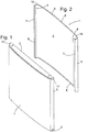
- Fig. 1 shows a perspective view of a door according to the invention, which can serve as a door of a refrigerator or freezer or as one of several doors of a combination refrigerator.
- the door comprises in known manner an outer wall 1, which is integrally formed from a sheet metal blank, an upper end element 2, a lower end element 3 and a in the view of Fig. 1 invisible inner wall.
- the outer wall 1 is in Fig. 2 to see in a perspective view, which essentially shows the hidden in the assembled state of the door inner surface of the outer wall 1.
- the outer wall is articulated in a slightly cambered front panel 4, two laterally adjoining the front panel 4 side edges 5 and two of the side edges 5 of the front panel 4 engaging behind edge webs 6.
- the edge webs 6 are each used to attach the rear wall, not shown. This is cut in a known per se and therefore not described in detail here manner of plastic sheet and formed by deep drawing.
- the outer wall 1 forms a respective hollow rib. 7
- a web 8 is angled in the horizontal direction in each case.
- the width of the web 8 is larger in each case in a central portion 9 than at its two ends 10.
- Fig. 3 shows in the perspective of Fig. 1 the upper end element 2 of the door.
- Fig. 4 is a section through the upper end element 2 along a in Fig. 3 level designated IV-IV.
- the injection-molded plastic end member 2 has a flat base plate 11 and a one-piece connected thereto and parallel to it second plate 12, which together defines a groove 13 open towards the front.
- the second plate 12 carries a plurality of in the groove thirteenth engaging, extending substantially in the depth direction of the groove 13 ribs 14.
- the second plate 12 is above a front edge 15 of the base plate 11 via. In a central region of the second plate 12 is at the front edge of a vertically downwardly extending, according to the crowning of the front plate 4 slightly curved web 16 is formed.
- the groove 13 takes in the finished assembled state of the door, the upper of the two webs 8 of the outer wall 1, wherein the web 8 between the ribs 14 and the base plate 11 is clamped. If the web 8 is properly inserted into the groove 13, the inside of the front plate 4 is supported on the web 16. Since the web 16 protrudes beyond the front edge 15 of the base plate 11, the front plate 4 resting against the web 16 also does so, so that a door-front which is free from scratches or steps and which is easy to clean is obtained.
- Two angled lugs 17 projecting at the longitudinal ends of the end element 2 are provided to be in the assembled condition as in FIG Fig. 1 shown outside abut the side edges 5 and to fix their position.
- a vertically oriented groove 19 extending along a rear edge 18 of the base plate 11 is provided to receive and fix an upper edge of the inner wall.
- bearing bushes 21 Two in the Fig. 3 visible openings 20 of the base plate belong to bearing bushes 21, which are provided to rotatably receive a bearing journal, not shown, fixed to a housing carrying the door.
- the bushings 21 are in a conventional manner at each end element in mirror-symmetrical arrangement twice available to allow mounting of the door to the housing optionally with left or right stop.
- Fig. 5 shows in perspective view one of two mutually mirror-symmetrical locking bodies 22, which are provided to be slipped over the bearing bushes 21 of the closing element 2 in each case after the joining of the closing element 2 with the outer wall 1, but before the assembly of the inner wall.
- the locking body 22 has a base 23, the shape of which is similar to a box open on one side, with an approximately quadrangular bottom plate 24 and the edges of the bottom plate 24 adjoining side walls 25 to 28.
- the bottom plate 24 contacts the base plate 11 of the end element 2
- the front side wall 25 nestles in extension of the web 16 from the inside to the front panel 4, wherein a recess 29 at the bottom of the side wall 25 receives the second plate 12 of the end element 2.
- the outer side wall 26 abuts against the inside of one of the side flanks 5, and a part of the side wall 27 contacts one of the edge webs 6.
- a rib-shaped projection 30 between the side walls 26, 27 engages in each case in one of the hollow ribs 7 of the outer wall 1.
- a sleeve 31 of the locking body 22 encloses the bearing bush 21 substantially free of play. In relation to the sleeve 31, radially oriented ribs 32 connect them to the side walls 26, 27, 28.
- the outer wall 1 and the end element 2 can be shaped so that the outer wall is put under tension and held pressed against the web 16 solely by the attachment of the locking body 22 at both ends of the end element 2. Due to the curvature of the web 16 then sets the outer wall 1 over the entire length of the web 16 away from tight against them and is not pushed away from the web 16 by the pressure acting on the inside of the front panel 4 during foaming from the inside. Such a tensile stress can be easily constructed, in particular, if the bearing bush 21 and the sleeve 31 receiving it are slightly conically shaped. As a result, the locking body 22 is driven further and outward against the side flanks 5, the farther it is pushed onto the bearing bush.
- Another advantage of the locking body 22 is that it reinforces the bushing 21, so that a resilient door hanger can be realized even with a relatively small wall thickness of the end element 2.
- the lower end element 3 can, as in Fig. 1 indicated, mirror image formed to the upper end element 2.
- one of the four bushings 21 of the end members 2, 3 is open at its tip projecting into the cavity of the door to serve as an injection port for a synthetic resin material which provides the foam expanding in the cavity.
- the other three bushings 21 located at the corners of the cavity farthest from the point of injection are then conveniently provided at their tips with a vent valve which allows the escape of air, but not foam, from the cavity.
- Fig. 6 shows a horizontal section through a part of the door, wherein one of the locking body 22 can be seen in plan view. It can be seen the sleeve 31, the outgoing therefrom ribs 32, the walls 25 to 28 and the tightly against the walls 25, 26, 27 and the protrusion 30 course of the outer wall. 1
- the tab 17 is in this embodiment, different from the illustration of Fig. 3 extended rearwardly around the hollow rib 7 and merges into a rib 33 forming an outer boundary of the groove 19, here denoted 34, of the inner wall of the door.
- Fig. 7 shows a section through the closing element 2 and the locking body 22 mounted thereon in a plane to the Fig. 4 parallel plane.
- the base plate 11, a the base plate 11 to the second plate 12 connecting vertical wall 35 and a groove 19 delimiting wall 45 of the end element 2 form a recess into which the base 23 of the locking body 22 engages positively.
- the locking body 22 is fixed in the recess by the insulating foam.
- An additional, even during assembly of the door effective fixation is formed by a recess or a window 36 in the wall 35 into which engages in the amount of the recess 29 formed on the locking body 22 locking projection 37.
- Fig. 8 shows a second embodiment of the closure element, denoted by 2 ', in one of Fig. 3 appropriate perspective;
- Fig. 9 shows the back of the end element 2 'in one of Fig. 2 appropriate perspective.
- Corresponding parts of this end element 2 'and the closure element 2 described above are provided with the same reference numerals.
- a base plate 11 and a second plate 12 define a forwardly open groove 13 into which ribs 14 protrude to clamp an angled web 8 of the outer wall 1 therein.
- a vertical rear wall 38 is integrally formed on the base plate 11.
- rearwardly and upwardly open recesses 39 are formed, which are provided to receive a not shown, protruding front body of the refrigerator arm, at its end in an opening 20 at the bottom of the recess 39 wearing bearing journals, and to hide the arm in front of the viewer in front of the device.
- the opening 20 belongs to a bearing bushing 21 projecting into the interior of the door.
- Fig. 10 shows a perspective view from below of a part of the closing element 2 ', each with one of the recesses 39 and the bearing bushes 21 and a part of the attached to the closing element 2' outer wall 1.
- the outer wall 1 at the End element 2 'anchored by the (in Fig. 10 covered) web 8 of the outer wall 1 in the groove 13 of the end element 2 ' engages.
- a wall 45 of the end element 2 ' which bounds the inner wall 34 (not shown) receiving groove 19, engages behind a short piece of the edge web 6 of the outer wall 1.
- a definitive anchorage is obtained by placing an in Fig. 10 separated from the outer wall 1 and the end element 2 'shown locking body 22' on the bearing bush 21 of the end element 2 'is pushed.
- the structure of the locking body 22 ' largely compensates for that of the locking body 22 Fig. 5 , with the difference that in the locking body 22 ', two tongues 41, 42 project beyond the bottom plate of the base 23 to each in the assembled state in a gap between the walls of the recess 39 and the side edge 5 and the front panel 4 of the outer wall 1 intervene.
- Fig. 11 shows a section through the tongue 42 engaging in a gap 43 between the recess 39 delimiting wall 44 and the front plate 4 supporting web 16.
- a latching projection 37 which engages in a recess of the web 16, the locking body 22 'with unsolvable connected to the end element 2 '.
Landscapes
- Engineering & Computer Science (AREA)
- Chemical & Material Sciences (AREA)
- Combustion & Propulsion (AREA)
- Physics & Mathematics (AREA)
- Mechanical Engineering (AREA)
- Thermal Sciences (AREA)
- General Engineering & Computer Science (AREA)
- Refrigerator Housings (AREA)
- Securing Of Glass Panes Or The Like (AREA)
Description
- Die vorliegende Erfindung betrifft eine Tür für ein Haushaltsgerät, insbesondere ein Kühl- oder Gefriergerät, mit einer der Tür, die mit einer Außenwand, einer Innenwand, einem oberen und einem unteren Abschlusselement ausgestattet ist, die einen inneren Hohlraum der Tür begrenzen. Ein solches Haushaltsgerät ist zum Beispiel aus
DE 103 02 797 A1 und ausDE 102 59 749 A1 bekannt. - Beim Ausschäumen des Hohlraums in der Tür übt das expandierende Schaummaterial Druck auf die Wände und die Abschlusselemente aus. Um zu verhindern, dass diese auseinandergetrieben werden und zwischen ihnen Schaum austritt, muss der Druck zumindest solange abgefangen werden, bis der Schaum abgebunden ist. Herkömmlicherweise geschieht dies, indem die oberen und unteren Ränder der Außenwand jeweils in eine Nut der Abschlusselemente eingesteckt werden, so dass eine Rippe des Abschlusselements, die die Nut nach außen begrenzt, den von innen her einwirkenden Druck abfängt. Eine Konsequenz dieser Bauweise ist, dass die Rippe stets über die Außenwand übersteht. Das Abschlusselement ist daher bei fertiger Tür deutlich sichtbar, und dort, wo die Außenwand in die Nut des Abschlusselements eintritt, bildet die Rippe Tür eine kleine Stufe, an der sich Schmutz sammeln kann.
- Es ist daher sowohl unter ästhetischen Gesichtspunkten als auch im Hinblick auf die Reinigungsfreundlichkeit wünschenswert, das eingangs beschriebene Haushaltsgerät mit der Tür so weiter zu entwickeln, dass ein Austreten von Schaum zwischen der Außenwand und dem Abschlusselement sicher vermieden werden kann, ohne dass hierfür eine über die Außenwand vorstehende Rippe am Abschlusselement erforderlich ist.
- Die Gebrauchsmusterschrift
DE 29 916 169 U1 zeigt eine gewölbte Tür für Kühlschränke. - Die Patentschrift
US 3,882,637 zeigt einen Kühlschrank mit einer Tür, wobei die Tür aus einem Außenpaneel und einer Rückwand besteht. - Die Offenlegungsschrift
JP 08 121 946 - Die Offenlegungsschrift
DE 10 208 061 A1 beschreibt ein Haushaltsgerät gemäß dem Oberbegriff des Anspruchs 1. - Die Patentschrift
US 6,192,630 B1 zeigt einen Kühlschrank mit einer Tür, welche aus einem äußeren Paneel mit Seitenflanken und Randstegen und einer Innenwand gebildet ist. An seitlichen Verläufen der Tür sind Rohre vorgesehen, welche in Aussparungen der vier Ekken der Tür eingreifen, so dass die einzelnen Wände der Tür miteinander verbunden sind. - Ferner is aus der
US 6,209,265 B1 eine Kühlschranktür mit einem Versteifungselement und einem abdeckelement bekannt. - Die Aufgabe wird erfindungsgemäß durch den Anspruch 1 gelöst Dieser Verriegelungskörper trägt wenigstens einen Teil der Kraft, die beim Ausschäumen auf die Außenwand einwirkt und verhindert so ein Abrücken der Außenwand von dem Abschlusselement nach vom, auch ohne dass eine vordere Rippe des Abschlusselements den Rand der Außenwand umgreift
- Anstelle der äußeren Rippe ist eine innere Rippe an dem Abschlusselement vorgesehen, die sich entlang eines horizontalen Randes der Außenwand erstreckt. Auf diese Rippe ist die Außenwand durch das Verriegelungselement aufgespannt gehalten, so dass kein Schaum zwischen die Außenwand und die Rippe eindringen kann. Um eine gleichmäßige Andrückkraft der Außenwand über die gesamte Länge der Rippe hinweg zu erreichen, ist es ferner zweckmäßig, wenn Rippe und Außenwand bombiert sind.
- Eine Verankerung des Verriegelungskörpers ist zweckmäßigerweise dadurch realisierbar, dass der Verriegelungskörper in einer zur Frontplatte parallelen Richtung mit einer Kontur des Abschlusselements formschlüssig zusammengesteckt ist. Eine beim Ausschäumen senkrecht zur Frontplatte wirkende Kraft kann den Verriegelungskörper dann nicht aus seinem Formschluss mit dem Abschlusselement lösen.
- Der Formschluss kann zweckmäßigerweise herbeigeführt werden, indem eine - herkömmlicherweise meist an den Abschlusselementen vorhandene - Türlagerbuchse in eine Hülse des Verriegelungskörpers eingreift.
- Eine solche Türlagerbuchse kann gleichzeitig als Einspritzöffnung zum Einspritzen von Isolationsmaterial in den inneren Hohlraum der Tür dienen, oder sie kann ein Entlüftungsventil aufnehmen, durch das beim Ausschäumen des Hohlraums Luft entweichen kann.
- Des Weiteren kann die Kontur des Abschlusselements an der Außenwand und der Innenwand anliegende Rippen umfassen, zwischen die der Verriegelungskörper eingreift.
- Um den Verriegelungskörper in seiner Position zu sichern, vor allem wenn er während des Zusammenbaus der Tür und vor dem Ausschäumen noch nicht durch den Isolierschaum in seiner Position gehalten ist, kann der Verriegelungskörper zweckmäßigerweise an dem Abschlusselement verrastet sein.
- Als eine weitere Maßnahme zur Absicherung gegen das Austreten von Schaum kann die Außenwand entlang wenigstens eines ihrer horizontalen Ränder einen zur Innenwand hin abgewinkelten Steg tragen, und das Abschlusselement kann eine zur Außenseite der Tür hin offene Nut aufweisen, in die der Steg eingreift.
- Um einerseits eine Klemmung des Stegs in der Nut zu gewährleisten und andererseits sicherzustellen, dass die zum Einschieben des Stegs in die Nut erforderliche Kraft nicht zu groß wird, ist zweckmäßigerweise die Nut breiter als der darin eingreifende Steg, und der Steg ist an von einer Seitenwand der Nut abstehenden Rippen geklemmt. Vorzugsweise ist die Seitenwand, die die Rippen trägt, die vom Schaum abgewandte unter den zwei Seitenwänden der Nut, so dass der Steg an der schaumseitigen Seitenwand eng anliegt und dort eine zusätzliche Dichtwirkung entfaltet.
- Indem der Steg einen oberen beziehungsweise unteren Abschluss der Seitenwand bildet, ist die Möglichkeit geschaffen, das Abschlusselement hinter die Frontseite der Tür zurücktreten zu lassen, wodurch das Abschlusselement vor den Augen eines Betrachtes weitgehend verborgen ist und eine von eventuell Schmutz sammelnden Stufen freie Frontseite erhalten werden kann.
- Für die Fixierung der Außenwand am Abschlusselement ist es zweckmäßig, wenn das Abschlusselement zwei außen an den Seitenflanken anliegende Laschen trägt. Diese hindern die Seitenflanken daran, sich auseinander zu biegen, wenn die Frontplatte der Außenwand unter Zugbelastung steht.
- Vorzugsweise ist die Seitenflanke zwischen dem Verriegelungskörper und der Lasche fixiert, so dass sie weder nach außen noch ins Innere der Tür hinein ausweichen kann.
- Um eine Zugspannung in der Außenwand aufzubauen und aufrecht zu erhalten, ist es nicht zuletzt vorteilhaft, wenn die Außenwand zwischen Seitenflanke und Randsteg jeweils eine hohle Rippe bildet und der Verriegelungskörper einen in den Hohlraum der Rippe eingreifenden Vorsprung aufweist.
- Weitere Vorteile der Erfindung ergeben sich aus der nachfolgenden Beschreibung von Ausführungsbeispielen unter Bezugnahme auf die beigefügten Figuren. Es zeigen:
- Fig. 1
- eine perspektivische Ansicht einer erfindungsgemäßen Tür;
- Fig. 2
- eine perspektivische Ansicht der Außenwand der Tür;
- Fig. 3
- ein Abschlusselement der Tür aus
Fig. 1 ; - Fig. 4
- einen Schnitt durch das Abschlusselement der
Fig. 3 ; - Fig. 5
- eine perspektivische Ansicht eines Verriegelungskörpers;
- Fig. 6
- einen horizontalen Schnitt durch die Tür, der den Verriegelungskörper in einer Draufsicht zeigt;
- Fig. 7
- einen Schnitt durch das Abschlusselement in einer Schnittebene parallel zu derjenigen der
Fig. 4 ; - Fig. 8
- eine perspektivische Ansicht von vorn eines Abschlusselementes gemäß einer zweiten Ausgestaltung;
- Fig. 9
- eine perspektivische Ansicht von hinten des Abschlusselements aus
Fig. 8 ; - Fig. 10
- eine fragmentarische perspektivische Ansicht des Abschlusselementes der
Fig. 8 , einer daran montierten Außenwand und eines daran zu montierenden Verriegelungskörpers, und - Fig. 11
- einen Teilschnitt durch das Abschlusselement, die Außenwand und den Verriegelungskörper der
Fig. 10 im zusammengefügten Zustand. -
Fig. 1 zeigt in perspektivischer Ansicht eine erfindungsgemäße Tür, die als Tür eines Kühl- oder Gefrierschrankes oder als eine von mehreren Türen eines Kombinations-Kältegerätes dienen kann. Die Tür umfasst in an sich bekannter Weise eine Außenwand 1, die aus einem Blechzuschnitt einstückig geformt ist, ein oberes Abschlusselement 2, ein unteres Abschlusselement 3 und eine in der Ansicht derFig. 1 nicht sichtbare Innenwand. - Die Außenwand 1 ist in
Fig. 2 in einer perspektivischen Ansicht zu sehen, die im Wesentlichen die im montierten Zustand der Tür verborgene Innenfläche der Außenwand 1 zeigt. Die Außenwand ist gegliedert in eine leicht bombierte Frontplatte 4, zwei jeweils seitlich an die Frontplatte 4 anschließende Seitenflanken 5 und zwei von den Seitenflanken 5 aus die Frontplatte 4 hintergreifende Randstege 6. Die Randstege 6 dienen jeweils zur Befestigung der nicht gezeigten Rückwand. Diese ist in an sich bekannter und daher hier nicht im Detail beschriebener Weise aus Kunststoff-Flachmaterial zugeschnitten und durch Tiefziehen geformt. - Zwischen den Seitenflanken 5 und den Randstegen 6 bildet die Außenwand 1 jeweils eine hohle Rippe 7.
- An den oberen und unteren Rändern der Außenwand 1 ist jeweils ein Steg 8 in horizontaler Richtung abgewinkelt. Die Breite des Steges 8 ist jeweils in einem mittleren Abschnitt 9 größer als an seinen beiden Enden 10.
-
Fig. 3 zeigt in der Perspektive derFig. 1 das obere Abschlusselement 2 der Tür.Fig. 4 ist ein Schnitt durch das obere Abschlusselement 2 entlang einer inFig. 3 mit IV-IV bezeichneten Ebene. Das aus Kunststoff spritzgeformte Abschlusselement 2 hat eine flache Grundplatte 11 und eine mit dieser einteilig zusammenhängende und zu ihr parallele zweite Platte 12, die zusammen eine nach vorn offene Nut 13 begrenzt. Die zweite Platte 12 trägt eine Mehrzahl von in die Nut 13 eingreifenden, sich im Wesentlichen in Tiefenrichtung der Nut 13 erstreckenden Rippen 14. Die zweite Platte 12 steht über einen vorderen Rand 15 der Grundplatte 11 über. In einem mittleren Bereich der zweiten Platte 12 ist an deren vorderen Rand ein sich vertikal nach unten erstreckender, entsprechend der Bombierung der Frontplatte 4 leicht gekrümmter Steg 16 angeformt. - Die Nut 13 nimmt im fertig montierten Zustand der Tür den oberen der beiden Stege 8 der Außenwand 1 auf, wobei der Steg 8 zwischen den Rippen 14 und der Grundplatte 11 geklemmt wird. Wenn der Steg 8 ordnungsgemäß in die Nut 13 eingeführt ist, ist die Innenseite der Frontplatte 4 an dem Steg 16 abgestützt. Da der Steg 16 über den vorderen Rand 15 der Grundplatte 11 übersteht, tut die an dem Steg 16 anliegende Frontplatte 4 dies auch, so dass eine reinigungsfreundliche, von Vorsprüngen oder Stufen freie Türvorderseite erhalten wird.
- Zwei an den Längsenden des Abschlusselementes 2 abstehende, gewinkelte Laschen 17 sind vorgesehen, um im zusammengebauten Zustand wie in
Fig. 1 gezeigt außen an den Seitenflanken 5 anzuliegen und deren Stellung zu fixieren. - Eine sich entlang eines rückwärtigen Randes 18 der Grundplatte 11 erstreckende vertikal orientierte Nut 19 ist vorgesehen, um einen oberen Rand der Innenwand aufzunehmen und zu fixieren.
- Zwei in der
Fig. 3 sichtbare Öffnungen 20 der Grundplatte gehören zu Lagerbuchsen 21, die vorgesehen sind, um einen nicht dargestellten, an einem die Tür tragenden Gehäuse festen Lagerzapfen drehbar aufzunehmen. Die Lagerbuchsen 21 sind in an sich bekannter Weise an jedem Abschlusselement in spiegelsymmetrischer Anordnung zweimal vorhanden, um eine Montage der Tür an dem Gehäuse wahlweise mit Links- oder mit Rechtsanschlag zu ermöglichen. -
Fig. 5 zeigt in perspektivischer Ansicht einen von zwei zueinander spiegelsymmetrischen Verriegelungskörpern 22, die vorgesehen sind, um jeweils nach dem Zusammenfügen des Abschlusselementes 2 mit der Außenwand 1, aber vor der Montage der Innenwand, über die Lagerbuchsen 21 des Abschlusselementes 2 gestülpt zu werden. Der Verriegelungskörper 22 hat eine Basis 23, deren Gestalt einem einseitig offenen Kasten ähnelt, mit einer in etwa viereckigen Bodenplatte 24 und an die Ränder der Bodenplatte 24 anschließenden Seitenwänden 25 bis 28. Im zusammengebauten Zustand berührt die Bodenplatte 24 die Grundplatte 11 des Abschlusselementes 2, die vordere Seitenwand 25 schmiegt sich in Verlängerung des Stegs 16 von innen an die Frontplatte 4 an, wobei eine Aussparung 29 am Fuß der Seitenwand 25 die zweite Platte 12 des Abschlusselementes 2 aufnimmt. Die äußere Seitenwand 26 liegt an der Innenseite einer der Seitenflanken 5 an, und ein Teil der Seitenwand 27 berührt einen der Randstege 6. Ein rippenförmiger Vorsprung 30 zwischen den Seitenwänden 26, 27 greift jeweils in eine der hohlen Rippen 7 der Außenwand 1 ein. Eine Hülse 31 des Verriegelungskörpers 22 umschließt im Wesentlichen spielfrei die Lagerbuchse 21. In Bezug auf die Hülse 31 radial orientierte Rippen 32 verbinden diese mit den Seitenwänden 26, 27, 28. - Die Außenwand 1 und das Abschlusselement 2 können so geformt sein, dass bereits allein durch die Anbringung der Verriegelungskörper 22 an beiden Enden des Abschlusselements 2 die Außenwand unter Spannung gesetzt und gegen den Steg 16 gedrückt gehalten wird. Aufgrund der Krümmung des Stegs 16 legt sich dann die Außenwand 1 über die gesamte Länge des Stegs 16 hinweg dicht an diesen an und wird auch durch den beim Ausschäumen von innen gegen die Frontplatte 4 wirkenden Druck nicht von dem Steg 16 fortgedrängt. Eine solche Zugspannung kann insbesondere dann leicht aufgebaut werden, wenn die Lagerbuchse 21 und die sie aufnehmende Hülse 31 leicht konisch geformt sind. Dadurch wird der Verriegelungskörper 22 umso weiter nach außen und gegen die Seitenflanken 5 getrieben, je weiter er auf die Lagerbuchse aufgeschoben wird.
- Es ist jedoch nicht zwingend notwendig, bereits bei der Anbringung des Verriegelungskörpers 22 die Außenwand unter Spannung zu setzen. Selbst wenn zu diesem Zeitpunkt die Außenwand 1 spannungslos bleibt, verhindert die Klemmung der Seitenflanken zwischen den Verriegelungskörpern 22 und den Laschen 17 sowie der Eingriff der Vorsprünge 30 in die hohlen Rippen 7, dass die Außenwand beim Ausschäumen dem von Innen einwirkenden Druck nachgibt. Falls dennoch Schaum zwischen die Frontplatte 4 und den Steg 16 gelangt, kann dieser nicht zwischen dem Steg 8 und der zweiten Platte 12 passieren, so dass die Schaumdichtigkeit dennoch gewährleistet ist.
- Ein weiterer Vorteil des Verriegelungskörpers 22 ist, dass er die Lagerbuchse 21 verstärkt, so dass eine belastbare Türaufhängung auch mit einer relativ geringen Wandstärke des Abschlusselementes 2 realisierbar ist.
- Das untere Abschlusselement 3 kann, wie in
Fig. 1 angedeutet, spiegelbildlich zu dem oberen Abschlusselement 2 ausgebildet sein. In diesem Fall ist vorzugsweise eine der vier Lagerbuchsen 21 der Abschlusselemente 2, 3 an ihrer in den Hohlraum der Tür hineinragenden Spitze offen, um als Einspritzöffnung für ein Kunstharzmaterial zu dienen, das den in dem Hohlraum expandierenden Schaum liefert. Die anderen drei Lagerbuchsen 21, die sich an den am weitesten von der Einspritzstelle entfernten Ecken des Hohlraums befinden, sind dann zweckmäßigerweise an ihrer Spitze jeweils mit einem Entlüftungsventil versehen, welches das Entweichen von Luft, nicht aber von Schaum, aus dem Hohlraum gestattet. -
Fig. 6 zeigt einen horizontalen Schnitt durch einen Teil der Tür, wobei einer der Verriegelungskörper 22 in Draufsicht zu sehen ist. Man erkennt die Hülse 31, die von ihr ausgehenden Rippen 32, die Wände 25 bis 28 sowie den eng an die Wände 25, 26, 27 und den Vorsprung 30 angeschmiegten Verlauf der Außenwand 1. Die Lasche 17 ist bei dieser Ausgestaltung, abweichend von der Darstellung derFig. 3 , nach hinten um die hohle Rippe 7 herum verlängert und geht über in eine Rippe 33, die eine äußere Begrenzung der die hier mit 34 bezeichnete Innenwand der Tür aufnehmenden Nut 19 bildet. -
Fig. 7 zeigt einen Schnitt durch das Abschlusselement 2 und den daran montierten Verriegelungskörper 22 in einer zur Ebene derFig. 4 parallelen Ebene. In dieser Ebene bilden die Grundplatte 11, eine die Grundplatte 11 mit der zweiten Platte 12 verbindende vertikale Wand 35 und eine die Nut 19 begrenzende Wand 45 des Abschlusselementes 2 eine Aussparung, in die die Basis 23 des Verriegelungskörpers 22 formschlüssig eingreift. Wenn die Tür fertig zusammengefügt und ausgeschäumt ist, ist der Verriegelungskörper 22 in der Aussparung durch den Isolierschaum fixiert. Eine zusätzliche, auch während des Zusammenbaus der Tür wirksame Fixierung wird durch eine Vertiefung oder ein Fenster 36 in der Wand 35 gebildet, in das ein in Höhe der Aussparung 29 an dem Verriegelungskörper 22 geformter Rastvorsprung 37 eingreift. Durch diesen Rastvorsprung 37 ist der Verriegelungskörper 22, wenn er einmal an dem Abschlusselement 2 montiert ist, unlösbar mit diesem verbunden. -
Fig. 8 zeigt eine zweite Ausgestaltung des Abschlusselementes, mit 2' bezeichnet, in einer derFig. 3 entsprechenden Perspektive;Fig. 9 zeigt die Rückseite des Abschlusselementes 2' in einer derFig. 2 entsprechenden Perspektive. Einander entsprechende Teile dieses Abschlusselements 2' und des oben beschriebenen Abschlusselementes 2 sind mit den gleichen Bezugszeichen versehen. Wie bei dem Abschlusselement 2 begrenzen eine Grundplatte 11 und eine zweite Platte 12 eine nach vorn offene Nut 13, in die Rippen 14 vorspringen, um darin einen abgewinkelten Steg 8 der Außenwand 1 zu klemmen. - An die Grundplatte 11 ist eine vertikale Rückwand 38 angeformt. In der Rückwand 38 und der Grundplatte 11 sind nach hinten und nach oben offene Ausnehmungen 39 gebildet, die vorgesehen sind, um einen nicht dargestellten, vorn Korpus des Kältegerätes abstehenden Arm aufzunehmen, der an seinem Ende einen in eine Öffnung 20 am Boden der Ausnehmung 39 eingreifenden Lagerzapfen trägt, und den Arm so vor den Blicken eines vor dem Gerät stehenden Betrachters zu verbergen. Wie beim Abschlusselement 2 gehört die Öffnung 20 zu einer ins Innere der Tür vorspringenden Lagerbuchse 21.
-
Fig. 10 zeigt eine perspektivische Ansicht von unten eines Teiles des Abschlusselementes 2' mit jeweils einer der Ausnehmungen 39 und der Lagerbuchsen 21 sowie eines Teiles der an dem Abschlusselement 2' befestigten Außenwand 1. Wie mit Bezug auf das Abschlusselement 2 beschrieben, ist die Außenwand 1 an dem Abschlusselement 2' verankert, indem der (inFig. 10 verdeckte) Steg 8 der Außenwand 1 in die Nut 13 des Abschlusselementes 2' eingreift. Im Gegensatz zum Abschlusselement 2 ist hier jedoch eine Wand 45 des Abschlusselementes 2', die die Innenwand 34 (nicht dargestellt) aufnehmende Nut 19 begrenzt, auf einem kurzen Stück von dem Randsteg 6 der Außenwand 1 hintergriffen. Es ist daher nicht möglich, das Abschlusselement 2' und die Außenwand 1 zusammenzufügen, indem lediglich beide horizontal gegeneinander geschoben und dabei der Steg 8 in die Nut 13 eingeführt wird; stattdessen muss beim Einschieben des Steges 8 in die Rippe 13 das Abschlusselement 2' etwas schräg gehalten sein, so dass der Randsteg 6 die Wand 45 passieren kann, und erst nach Passieren dieser Wand 45 wird das Abschlusselement 2' um eine horizontale Achse 40 (sieheFig. 8 ) geschwenkt, so dass ein Ende des Randsteges 6 an der Wand 45 zur Anlage kommt, wie inFig. 10 gezeigt. Auf diese Weise wird eine erste, provisorische Verankerung der Außenwand 1 an dem Abschlusselement 2' erhalten. - Eine definitive Verankerung wird erhalten, indem ein in
Fig. 10 getrennt von der Außenwand 1 und dem Abschlusselement 2' dargestellter Verriegelungskörper 22' auf die Lagerbuchse 21 des Abschlusselementes 2' aufgeschoben wird. Der Aufbau des Verriegelungskörpers 22' gleicht weitgehend dem des Verriegelungskörpers 22 ausFig. 5 , mit dem Unterschied, dass bei dem Verriegelungskörper 22' zwei Zungen 41, 42 über die Bodenplatte der Basis 23 hinaus überstehen, um im montierten Zustand jeweils in einen Spalt zwischen den Wänden der Ausnehmung 39 und der Seitenflanke 5 bzw. der Frontplatte 4 der Außenwand 1 einzugreifen. -
Fig. 11 zeigt einen Schnitt durch die Zunge 42 eingreifend in einen Spalt 43 zwischen einer die Aussparung 39 begrenzenden Wand 44 und dem die Frontplatte 4 abstützenden Steg 16. Durch einen Rastvorsprung 37, der in eine Aussparung des Stegs 16 eingreift, ist der Verriegelungskörper 22' unlösbar mit dem Abschlusselement 2' verbunden.
Claims (13)
- Haushaltsgerät, insbesondere Haushaltskältegerät mit einer Tür, die mit einer Außenwand (1), einer Innenwand (34) und einem oberen und einem unteren Abschlusselement (2, 3) ausgestattet ist, die einen inneren Hohlraum der Tür begrenzen, wobei die Außenwand (1) eine Frontplatte (4) und zwei an die Frontplatte (4) angrenzende Seitenflanken (5) der Tür bildet und die Seitenflanken (5) hinter die Frontplatte (4) greifende Randstege (6) tragen, wobei in eine von einer der Seitenflanken (5), einem der Randstege (6) und einem der Abschlusselemente (2, 3) gebildete Ecke des inneren Hohlraums ein Verriegelungskörper (22) eingefügt ist, durch welchen ein Austreten von Schaum zwischen der Außenwand und diesem Abschlusselement sicher vermieden wird, und das Abschlusselement (2, 3) einen Steg (16) trägt, der sich entlang eines horizontalen Randes der Außenwand (1) erstreckt, wobei die Außenwand (1) durch den Verriegelungskörper (22) auf den Steg (16) aufgespannt gehalten ist.
- Haushaltsgerät nach Anspruch 1, dadurch gekennzeichnet, dass der Verriegelungskörper (22) in einer zur Frontplatte (4) parallelen Richtung mit einer Kontur des Abschlusselements (2, 3) formschlüssig zusammengesteckt ist.
- Haushaltsgerät nach Anspruch 2, dadurch gekennzeichnet, dass die Kontur des Abschlusselements (2, 3) eine Türlagerbuchse (21) umfasst, die in eine Hülse (31) des Verriegelungskörpers (22) eingreift.
- Haushaltsgerät nach Anspruch 3, dadurch gekennzeichnet, dass die Türlagerbuchse (21) als Einspritzöffnung zum Einspritzen von Isolationsmaterial in den inneren Hohlraum der Tür dient.
- Haushaltsgerät nach Anspruch 3, dadurch gekennzeichnet, dass in der Türlagerbuchse (21) ein Entlüftungsventil zum Entlüften des inneren Hohlraums der Tür untergebracht ist.
- Haushaltsgerät nach einem der Ansprüche 2 bis 5, dadurch gekennzeichnet, dass die Kontur des Abschlusselements (2, 3; 2') an der Außenwand (1) und der Innenwand (34) anliegende Rippen (16, 35, 45) umfasst, zwischen die der Verriegelungskörper (22) eingreift.
- Haushaltsgerät nach einem der Ansprüche 2 bis 6, dadurch gekennzeichnet, dass der Verriegelungskörper (22) an dem Abschlusselement (2, 3; 2') verrastet ist.
- Haushaltsgerät nach einem der vorhergehenden Ansprüche, dadurch gekennzeichnet, dass die Außenwand (1) entlang wenigstens eines ihrer horizontalen Ränder einen zur Innenwand (34) hin abgewinkelten Steg (8) trägt, und dass das Abschlusselement (2; 2') eine zur Außenseite der Tür hin offene Nut (13) aufweist, in die der Steg (8) eingreift.
- Haushaltsgerät nach Anspruch 8, dadurch gekennzeichnet, dass die Nut (13) breiter ist als der darin eingreifende Steg (8) und dass der Steg (8) an von einer Seitenwand (12) der Nut abstehenden Rippen (14) geklemmt ist.
- Haushaltsgerät nach Anspruch 8 oder 9, dadurch gekennzeichnet, dass ein vorderer Rand (15) des Abschlusselements (2) hinter die Frontseite der Tür zurückspringt.
- Haushaltsgerät nach einem der vorhergehenden Ansprüche, dadurch gekennzeichnet, dass das Abschlusselement (2; 2') zwei außen an den Seitenflanken (5) anliegende Laschen (17) trägt.
- Haushaltsgerät nach Anspruch 11, dadurch gekennzeichnet, dass die Seitenflanke (5) zwischen dem Verriegelungskörper (22) und der Lasche (17) fixiert ist.
- Haushaltsgerät nach einem der vorhergehenden Ansprüche, dadurch gekennzeichnet, dass die Außenwand (1) zwischen Seitenflanke (5) und Randsteg (6) jeweils eine hohle Rippe (7) bildet und dass der Verriegelungskörper (22, 22') einen in den Hohlraum der Rippe (7) eingreifenden Vorsprung (30) aufweist.
Applications Claiming Priority (2)
| Application Number | Priority Date | Filing Date | Title |
|---|---|---|---|
| DE202007007321U DE202007007321U1 (de) | 2007-05-23 | 2007-05-23 | Haushaltsgerät |
| PCT/EP2008/055927 WO2008141995A2 (de) | 2007-05-23 | 2008-05-14 | Haushaltsgerät |
Publications (3)
| Publication Number | Publication Date |
|---|---|
| EP2153149A2 EP2153149A2 (de) | 2010-02-17 |
| EP2153149B1 EP2153149B1 (de) | 2011-07-20 |
| EP2153149B2 true EP2153149B2 (de) | 2018-11-28 |
Family
ID=38320463
Family Applications (1)
| Application Number | Title | Priority Date | Filing Date |
|---|---|---|---|
| EP08759605.2A Active EP2153149B2 (de) | 2007-05-23 | 2008-05-14 | Haushaltsgerät |
Country Status (8)
| Country | Link |
|---|---|
| US (1) | US20100170290A1 (de) |
| EP (1) | EP2153149B2 (de) |
| CN (1) | CN101680703B (de) |
| AT (1) | ATE517299T1 (de) |
| DE (1) | DE202007007321U1 (de) |
| ES (1) | ES2368970T3 (de) |
| RU (1) | RU2009145636A (de) |
| WO (1) | WO2008141995A2 (de) |
Families Citing this family (23)
| Publication number | Priority date | Publication date | Assignee | Title |
|---|---|---|---|---|
| DE102008021345A1 (de) * | 2008-04-29 | 2009-11-05 | BSH Bosch und Siemens Hausgeräte GmbH | Tür für ein Haushaltsgerät |
| DE102008041975A1 (de) * | 2008-09-10 | 2010-03-11 | BSH Bosch und Siemens Hausgeräte GmbH | Haushaltskältegerät mit zumindest einer Tür |
| DE102010005185A1 (de) * | 2009-12-16 | 2011-06-22 | Liebherr-Hausgeräte Lienz Gmbh | Tür oder Deckel für Kühl- und/oder Gefriergerät |
| DE102010027918A1 (de) | 2010-04-19 | 2011-10-20 | BSH Bosch und Siemens Hausgeräte GmbH | Türblatt, Verfahren zum Herstellen eines Türblatts und Kältegerät mit einem Türblatt |
| DE102010027922A1 (de) | 2010-04-19 | 2011-10-20 | BSH Bosch und Siemens Hausgeräte GmbH | Türblatt und Kältegerät mit einem Türblatt |
| DE102010027921A1 (de) | 2010-04-19 | 2011-10-20 | BSH Bosch und Siemens Hausgeräte GmbH | Türblatt, Verfahren zum Herstellen eines Türblatts und Kältegerät mit einem Türblatt |
| DE102011005738A1 (de) * | 2011-03-17 | 2012-09-20 | BSH Bosch und Siemens Hausgeräte GmbH | Kältegerättür |
| DE102012200813A1 (de) * | 2012-01-20 | 2013-07-25 | BSH Bosch und Siemens Hausgeräte GmbH | Wärmedämmende Tür für ein Kältegerät |
| CN102538354B (zh) * | 2012-03-16 | 2016-12-14 | 海尔集团公司 | 门壳角部结构及冰箱门体 |
| US9084527B2 (en) | 2013-06-24 | 2015-07-21 | Wolf Appliances, Inc. | Door for an appliance |
| USD710557S1 (en) | 2013-06-24 | 2014-08-05 | Wolf Appliance, Inc. | Dishwasher door |
| US9435579B1 (en) | 2015-04-10 | 2016-09-06 | Electrolux Home Products, Inc. | Insulated door assembly |
| USD952703S1 (en) * | 2019-08-08 | 2022-05-24 | Samsung Electronics Co., Ltd. | Panel for refrigerator |
| USD952706S1 (en) * | 2019-08-08 | 2022-05-24 | Samsung Electronics Co., Ltd. | Panel for refrigerator |
| USD951308S1 (en) * | 2019-08-08 | 2022-05-10 | Samsung Electronics Co., Ltd. | Panel for refrigerator |
| USD952704S1 (en) * | 2019-08-08 | 2022-05-24 | Samsung Electronics Co., Ltd. | Panel for refrigerator |
| USD952707S1 (en) * | 2019-08-08 | 2022-05-24 | Samsung Electronics Co., Ltd. | Panel for refrigerator |
| USD952709S1 (en) * | 2019-08-08 | 2022-05-24 | Samsung Electronics Co., Ltd. | Panel for refrigerator |
| USD952708S1 (en) * | 2019-08-08 | 2022-05-24 | Samsung Electronics Co., Ltd. | Panel for refrigerator |
| USD952705S1 (en) * | 2019-08-08 | 2022-05-24 | Samsung Electronics Co., Ltd. | Panel for refrigerator |
| DE102020116127A1 (de) | 2020-06-18 | 2021-12-23 | Rahrbach Gmbh | Verriegelungsvorrichtung mit Entlüftungskanal |
| JP7405719B2 (ja) * | 2020-09-14 | 2023-12-26 | 日立グローバルライフソリューションズ株式会社 | 冷蔵庫 |
| WO2022108083A1 (ko) * | 2020-11-18 | 2022-05-27 | 삼성전자주식회사 | 냉장고 |
Citations (9)
| Publication number | Priority date | Publication date | Assignee | Title |
|---|---|---|---|---|
| US3006708A (en) † | 1960-04-21 | 1961-10-31 | Gen Motors Corp | Refrigerator cabinet |
| DE1243846B (de) † | 1964-02-25 | 1967-07-06 | ||
| US3776143A (en) † | 1971-10-14 | 1973-12-04 | Pullman Inc | Railway passenger vehicle step and door construction |
| GB1508582A (en) † | 1975-02-07 | 1978-04-26 | Bridgewater M | Frames for windows or doors |
| US4486981A (en) † | 1981-06-30 | 1984-12-11 | Electrolux S.A.R.L. | Refrigerator door |
| US5987910A (en) † | 1996-12-02 | 1999-11-23 | Waggonbau Elze Gmbh & Co. Besitz Kg | Large-volume insulated shipping container |
| US6209265B1 (en) † | 1999-05-27 | 2001-04-03 | Camco Inc. | Refrigerator door corner construction |
| US20020190617A1 (en) † | 2001-06-14 | 2002-12-19 | Nedo Banicevic | Thermal and reinforced refrigerator door |
| US20060265960A1 (en) † | 2005-05-27 | 2006-11-30 | Maytag Corporation | Refrigerator door with end cap |
Family Cites Families (13)
| Publication number | Priority date | Publication date | Assignee | Title |
|---|---|---|---|---|
| US1630100A (en) * | 1926-01-11 | 1927-05-24 | Electric Refrigeration Corp | Refrigerator door |
| US3882637A (en) * | 1973-11-12 | 1975-05-13 | Whirlpool Co | Refrigerator door construction and method of forming the same |
| JP3677794B2 (ja) | 1994-10-25 | 2005-08-03 | 株式会社日立製作所 | 冷蔵庫の扉 |
| DE19747769C2 (de) * | 1997-10-29 | 1999-12-16 | Bsh Bosch Siemens Hausgeraete | Haushaltsgerät mit Frontblende |
| IT245325Y1 (it) | 1998-10-06 | 2002-03-20 | Electrolux Zanussi Grandi Impi | Porte bombate perfezionate per apparecchi frigoriferi |
| CA2252299C (en) * | 1998-10-30 | 2006-06-13 | Camco Inc. | Refrigerator door construction |
| CA2273475C (en) | 1999-05-27 | 2004-07-13 | Nedo Banicevic | Refrigerator door epaulet |
| CN1179179C (zh) * | 2002-01-31 | 2004-12-08 | 乐金电子(天津)电器有限公司 | 冰箱门气孔结构 |
| DE10208061B4 (de) | 2002-02-25 | 2015-01-22 | BSH Bosch und Siemens Hausgeräte GmbH | Kältegerätetür und damit ausgestattetes Kältegerät |
| DE10259749A1 (de) | 2002-12-19 | 2004-07-08 | BSH Bosch und Siemens Hausgeräte GmbH | Kältegerät und Tür für ein Kältegerät |
| DE10302797B4 (de) | 2003-01-24 | 2025-05-28 | BSH Hausgeräte GmbH | Tür für ein Kältegerät und Kältegerät, umfassend eine Tür |
| CN100473924C (zh) * | 2004-01-29 | 2009-04-01 | 乐金电子(天津)电器有限公司 | 冰箱门的装饰物 |
| JP4179244B2 (ja) * | 2004-08-06 | 2008-11-12 | 三菱電機株式会社 | 冷蔵庫 |
-
2007
- 2007-05-23 DE DE202007007321U patent/DE202007007321U1/de not_active Expired - Lifetime
-
2008
- 2008-05-14 ES ES08759605T patent/ES2368970T3/es active Active
- 2008-05-14 AT AT08759605T patent/ATE517299T1/de active
- 2008-05-14 WO PCT/EP2008/055927 patent/WO2008141995A2/de not_active Ceased
- 2008-05-14 RU RU2009145636/21A patent/RU2009145636A/ru not_active Application Discontinuation
- 2008-05-14 EP EP08759605.2A patent/EP2153149B2/de active Active
- 2008-05-14 CN CN2008800171417A patent/CN101680703B/zh active Active
- 2008-05-14 US US12/600,683 patent/US20100170290A1/en not_active Abandoned
Patent Citations (9)
| Publication number | Priority date | Publication date | Assignee | Title |
|---|---|---|---|---|
| US3006708A (en) † | 1960-04-21 | 1961-10-31 | Gen Motors Corp | Refrigerator cabinet |
| DE1243846B (de) † | 1964-02-25 | 1967-07-06 | ||
| US3776143A (en) † | 1971-10-14 | 1973-12-04 | Pullman Inc | Railway passenger vehicle step and door construction |
| GB1508582A (en) † | 1975-02-07 | 1978-04-26 | Bridgewater M | Frames for windows or doors |
| US4486981A (en) † | 1981-06-30 | 1984-12-11 | Electrolux S.A.R.L. | Refrigerator door |
| US5987910A (en) † | 1996-12-02 | 1999-11-23 | Waggonbau Elze Gmbh & Co. Besitz Kg | Large-volume insulated shipping container |
| US6209265B1 (en) † | 1999-05-27 | 2001-04-03 | Camco Inc. | Refrigerator door corner construction |
| US20020190617A1 (en) † | 2001-06-14 | 2002-12-19 | Nedo Banicevic | Thermal and reinforced refrigerator door |
| US20060265960A1 (en) † | 2005-05-27 | 2006-11-30 | Maytag Corporation | Refrigerator door with end cap |
Also Published As
| Publication number | Publication date |
|---|---|
| US20100170290A1 (en) | 2010-07-08 |
| WO2008141995A3 (de) | 2009-05-28 |
| ATE517299T1 (de) | 2011-08-15 |
| EP2153149A2 (de) | 2010-02-17 |
| DE202007007321U1 (de) | 2007-07-26 |
| CN101680703B (zh) | 2012-02-01 |
| ES2368970T3 (es) | 2011-11-24 |
| WO2008141995A2 (de) | 2008-11-27 |
| RU2009145636A (ru) | 2011-06-27 |
| CN101680703A (zh) | 2010-03-24 |
| EP2153149B1 (de) | 2011-07-20 |
Similar Documents
| Publication | Publication Date | Title |
|---|---|---|
| EP2153149B2 (de) | Haushaltsgerät | |
| EP2153147B1 (de) | Haushaltsgerät | |
| EP2153148B1 (de) | Haushaltsgerät | |
| EP2118596B1 (de) | Haushaltsgerät mit trägersystem | |
| DE9314021U1 (de) | Zerlegbarer Käfig | |
| DE69807805T3 (de) | Plastikdichtung mit verformbarem Unterteil für Kühlschränke | |
| DE10117763A1 (de) | Abstellbehälter für Kältegeräte | |
| EP0599161A1 (de) | Dichtungsanordnung, insbesondere für die Tür eines Kühl- oder Gefriergerätes | |
| WO2009000718A2 (de) | Haushalts-kältegerät mit einbauteil | |
| WO2006120069A1 (de) | Tür für ein kältegerät | |
| EP1882137A1 (de) | Tür für ein haushaltsgerät | |
| DE102009028428A1 (de) | Kältegerät mit einem Einbauteil | |
| WO2016165919A1 (de) | Tür für ein haushaltskältegerät mit verrasteter abschlussleiste, haushaltskältegerät und verfahren zum herstellen einer tür | |
| EP1926956B1 (de) | Kältegerät | |
| DE4304500A1 (de) | Dichtungsanordnung, insbesondere für die Tür eines Kühl- oder Gefriergerätes | |
| EP2107325A1 (de) | Gehäuse fur ein Haushaltsgerät | |
| EP2311347B1 (de) | Verschlusselement zum Verschließen eines Spaltes zwischen Einbaugerät und Möbelumbau | |
| EP2281159B1 (de) | Tür für ein haushaltsgerät | |
| EP1110045B1 (de) | Tür eines kühl- oder gefriergerätes mit einer dichtung | |
| DE29619300U1 (de) | Profil zur Dichtung einer Tür | |
| EP2561291A2 (de) | Türblatt, verfahren zum herstellen eines türblatts und kältegerät mit einem türblatt | |
| DE102019216193A1 (de) | Haushaltsgerät mit einem Scharnier und Scharnier für ein Haushaltsgerät | |
| DE102013210015B4 (de) | Führungsschiene für eine Geschirrspülmaschine | |
| DE102008028585A1 (de) | Eis-/Flüssigkeitsspendernische | |
| EP1934539A1 (de) | Tür für ein kältegerät |
Legal Events
| Date | Code | Title | Description |
|---|---|---|---|
| PUAI | Public reference made under article 153(3) epc to a published international application that has entered the european phase |
Free format text: ORIGINAL CODE: 0009012 |
|
| 17P | Request for examination filed |
Effective date: 20091223 |
|
| AK | Designated contracting states |
Kind code of ref document: A2 Designated state(s): AT BE BG CH CY CZ DE DK EE ES FI FR GB GR HR HU IE IS IT LI LT LU LV MC MT NL NO PL PT RO SE SI SK TR |
|
| AX | Request for extension of the european patent |
Extension state: AL BA MK RS |
|
| 17Q | First examination report despatched |
Effective date: 20100802 |
|
| GRAP | Despatch of communication of intention to grant a patent |
Free format text: ORIGINAL CODE: EPIDOSNIGR1 |
|
| DAX | Request for extension of the european patent (deleted) | ||
| GRAS | Grant fee paid |
Free format text: ORIGINAL CODE: EPIDOSNIGR3 |
|
| GRAA | (expected) grant |
Free format text: ORIGINAL CODE: 0009210 |
|
| AK | Designated contracting states |
Kind code of ref document: B1 Designated state(s): AT BE BG CH CY CZ DE DK EE ES FI FR GB GR HR HU IE IS IT LI LT LU LV MC MT NL NO PL PT RO SE SI SK TR |
|
| REG | Reference to a national code |
Ref country code: GB Ref legal event code: FG4D Free format text: NOT ENGLISH |
|
| REG | Reference to a national code |
Ref country code: CH Ref legal event code: EP |
|
| REG | Reference to a national code |
Ref country code: DE Ref legal event code: R096 Ref document number: 502008004262 Country of ref document: DE Effective date: 20110915 |
|
| REG | Reference to a national code |
Ref country code: NL Ref legal event code: VDEP Effective date: 20110720 |
|
| REG | Reference to a national code |
Ref country code: ES Ref legal event code: FG2A Ref document number: 2368970 Country of ref document: ES Kind code of ref document: T3 Effective date: 20111124 |
|
| PG25 | Lapsed in a contracting state [announced via postgrant information from national office to epo] |
Ref country code: NO Free format text: LAPSE BECAUSE OF FAILURE TO SUBMIT A TRANSLATION OF THE DESCRIPTION OR TO PAY THE FEE WITHIN THE PRESCRIBED TIME-LIMIT Effective date: 20111020 Ref country code: FI Free format text: LAPSE BECAUSE OF FAILURE TO SUBMIT A TRANSLATION OF THE DESCRIPTION OR TO PAY THE FEE WITHIN THE PRESCRIBED TIME-LIMIT Effective date: 20110720 Ref country code: HR Free format text: LAPSE BECAUSE OF FAILURE TO SUBMIT A TRANSLATION OF THE DESCRIPTION OR TO PAY THE FEE WITHIN THE PRESCRIBED TIME-LIMIT Effective date: 20110720 Ref country code: SE Free format text: LAPSE BECAUSE OF FAILURE TO SUBMIT A TRANSLATION OF THE DESCRIPTION OR TO PAY THE FEE WITHIN THE PRESCRIBED TIME-LIMIT Effective date: 20110720 Ref country code: PT Free format text: LAPSE BECAUSE OF FAILURE TO SUBMIT A TRANSLATION OF THE DESCRIPTION OR TO PAY THE FEE WITHIN THE PRESCRIBED TIME-LIMIT Effective date: 20111121 Ref country code: LT Free format text: LAPSE BECAUSE OF FAILURE TO SUBMIT A TRANSLATION OF THE DESCRIPTION OR TO PAY THE FEE WITHIN THE PRESCRIBED TIME-LIMIT Effective date: 20110720 Ref country code: IS Free format text: LAPSE BECAUSE OF FAILURE TO SUBMIT A TRANSLATION OF THE DESCRIPTION OR TO PAY THE FEE WITHIN THE PRESCRIBED TIME-LIMIT Effective date: 20111120 Ref country code: NL Free format text: LAPSE BECAUSE OF FAILURE TO SUBMIT A TRANSLATION OF THE DESCRIPTION OR TO PAY THE FEE WITHIN THE PRESCRIBED TIME-LIMIT Effective date: 20110720 |
|
| REG | Reference to a national code |
Ref country code: IE Ref legal event code: FD4D |
|
| PG25 | Lapsed in a contracting state [announced via postgrant information from national office to epo] |
Ref country code: PL Free format text: LAPSE BECAUSE OF FAILURE TO SUBMIT A TRANSLATION OF THE DESCRIPTION OR TO PAY THE FEE WITHIN THE PRESCRIBED TIME-LIMIT Effective date: 20110720 Ref country code: CY Free format text: LAPSE BECAUSE OF FAILURE TO SUBMIT A TRANSLATION OF THE DESCRIPTION OR TO PAY THE FEE WITHIN THE PRESCRIBED TIME-LIMIT Effective date: 20110720 Ref country code: SI Free format text: LAPSE BECAUSE OF FAILURE TO SUBMIT A TRANSLATION OF THE DESCRIPTION OR TO PAY THE FEE WITHIN THE PRESCRIBED TIME-LIMIT Effective date: 20110720 Ref country code: LV Free format text: LAPSE BECAUSE OF FAILURE TO SUBMIT A TRANSLATION OF THE DESCRIPTION OR TO PAY THE FEE WITHIN THE PRESCRIBED TIME-LIMIT Effective date: 20110720 |
|
| PLBI | Opposition filed |
Free format text: ORIGINAL CODE: 0009260 |
|
| PG25 | Lapsed in a contracting state [announced via postgrant information from national office to epo] |
Ref country code: IE Free format text: LAPSE BECAUSE OF FAILURE TO SUBMIT A TRANSLATION OF THE DESCRIPTION OR TO PAY THE FEE WITHIN THE PRESCRIBED TIME-LIMIT Effective date: 20110720 Ref country code: CZ Free format text: LAPSE BECAUSE OF FAILURE TO SUBMIT A TRANSLATION OF THE DESCRIPTION OR TO PAY THE FEE WITHIN THE PRESCRIBED TIME-LIMIT Effective date: 20110720 Ref country code: SK Free format text: LAPSE BECAUSE OF FAILURE TO SUBMIT A TRANSLATION OF THE DESCRIPTION OR TO PAY THE FEE WITHIN THE PRESCRIBED TIME-LIMIT Effective date: 20110720 |
|
| PLAX | Notice of opposition and request to file observation + time limit sent |
Free format text: ORIGINAL CODE: EPIDOSNOBS2 |
|
| 26 | Opposition filed |
Opponent name: INDESIT COMPANY S.P.A. Effective date: 20120420 |
|
| PG25 | Lapsed in a contracting state [announced via postgrant information from national office to epo] |
Ref country code: EE Free format text: LAPSE BECAUSE OF FAILURE TO SUBMIT A TRANSLATION OF THE DESCRIPTION OR TO PAY THE FEE WITHIN THE PRESCRIBED TIME-LIMIT Effective date: 20110720 Ref country code: RO Free format text: LAPSE BECAUSE OF FAILURE TO SUBMIT A TRANSLATION OF THE DESCRIPTION OR TO PAY THE FEE WITHIN THE PRESCRIBED TIME-LIMIT Effective date: 20110720 |
|
| PG25 | Lapsed in a contracting state [announced via postgrant information from national office to epo] |
Ref country code: DK Free format text: LAPSE BECAUSE OF FAILURE TO SUBMIT A TRANSLATION OF THE DESCRIPTION OR TO PAY THE FEE WITHIN THE PRESCRIBED TIME-LIMIT Effective date: 20110720 |
|
| REG | Reference to a national code |
Ref country code: DE Ref legal event code: R026 Ref document number: 502008004262 Country of ref document: DE Effective date: 20120420 |
|
| PLBB | Reply of patent proprietor to notice(s) of opposition received |
Free format text: ORIGINAL CODE: EPIDOSNOBS3 |
|
| BERE | Be: lapsed |
Owner name: BSH BOSCH UND SIEMENS HAUSGERATE G.M.B.H. Effective date: 20120531 |
|
| PG25 | Lapsed in a contracting state [announced via postgrant information from national office to epo] |
Ref country code: MC Free format text: LAPSE BECAUSE OF NON-PAYMENT OF DUE FEES Effective date: 20120531 |
|
| REG | Reference to a national code |
Ref country code: CH Ref legal event code: PL |
|
| PG25 | Lapsed in a contracting state [announced via postgrant information from national office to epo] |
Ref country code: LI Free format text: LAPSE BECAUSE OF NON-PAYMENT OF DUE FEES Effective date: 20120531 Ref country code: CH Free format text: LAPSE BECAUSE OF NON-PAYMENT OF DUE FEES Effective date: 20120531 |
|
| PG25 | Lapsed in a contracting state [announced via postgrant information from national office to epo] |
Ref country code: BE Free format text: LAPSE BECAUSE OF NON-PAYMENT OF DUE FEES Effective date: 20120531 |
|
| PG25 | Lapsed in a contracting state [announced via postgrant information from national office to epo] |
Ref country code: BG Free format text: LAPSE BECAUSE OF FAILURE TO SUBMIT A TRANSLATION OF THE DESCRIPTION OR TO PAY THE FEE WITHIN THE PRESCRIBED TIME-LIMIT Effective date: 20111020 |
|
| PG25 | Lapsed in a contracting state [announced via postgrant information from national office to epo] |
Ref country code: MT Free format text: LAPSE BECAUSE OF FAILURE TO SUBMIT A TRANSLATION OF THE DESCRIPTION OR TO PAY THE FEE WITHIN THE PRESCRIBED TIME-LIMIT Effective date: 20110720 |
|
| PG25 | Lapsed in a contracting state [announced via postgrant information from national office to epo] |
Ref country code: LU Free format text: LAPSE BECAUSE OF NON-PAYMENT OF DUE FEES Effective date: 20120514 |
|
| REG | Reference to a national code |
Ref country code: AT Ref legal event code: MM01 Ref document number: 517299 Country of ref document: AT Kind code of ref document: T Effective date: 20130514 |
|
| PG25 | Lapsed in a contracting state [announced via postgrant information from national office to epo] |
Ref country code: HU Free format text: LAPSE BECAUSE OF FAILURE TO SUBMIT A TRANSLATION OF THE DESCRIPTION OR TO PAY THE FEE WITHIN THE PRESCRIBED TIME-LIMIT Effective date: 20080514 |
|
| PG25 | Lapsed in a contracting state [announced via postgrant information from national office to epo] |
Ref country code: AT Free format text: LAPSE BECAUSE OF NON-PAYMENT OF DUE FEES Effective date: 20130514 Ref country code: GR Free format text: LAPSE BECAUSE OF FAILURE TO SUBMIT A TRANSLATION OF THE DESCRIPTION OR TO PAY THE FEE WITHIN THE PRESCRIBED TIME-LIMIT Effective date: 20110720 |
|
| RAP2 | Party data changed (patent owner data changed or rights of a patent transferred) |
Owner name: BSH HAUSGERAETE GMBH |
|
| REG | Reference to a national code |
Ref country code: DE Ref legal event code: R081 Ref document number: 502008004262 Country of ref document: DE Owner name: BSH HAUSGERAETE GMBH, DE Free format text: FORMER OWNER: BSH BOSCH UND SIEMENS HAUSGERAETE GMBH, 81739 MUENCHEN, DE Effective date: 20150408 |
|
| REG | Reference to a national code |
Ref country code: FR Ref legal event code: PLFP Year of fee payment: 8 |
|
| REG | Reference to a national code |
Ref country code: ES Ref legal event code: PC2A Owner name: BSH HAUSGERATE GMBH Effective date: 20150529 |
|
| PGFP | Annual fee paid to national office [announced via postgrant information from national office to epo] |
Ref country code: GB Payment date: 20150521 Year of fee payment: 8 Ref country code: ES Payment date: 20150520 Year of fee payment: 8 |
|
| PGFP | Annual fee paid to national office [announced via postgrant information from national office to epo] |
Ref country code: FR Payment date: 20150519 Year of fee payment: 8 |
|
| APBM | Appeal reference recorded |
Free format text: ORIGINAL CODE: EPIDOSNREFNO |
|
| APBP | Date of receipt of notice of appeal recorded |
Free format text: ORIGINAL CODE: EPIDOSNNOA2O |
|
| APAH | Appeal reference modified |
Free format text: ORIGINAL CODE: EPIDOSCREFNO |
|
| APAW | Appeal reference deleted |
Free format text: ORIGINAL CODE: EPIDOSDREFNO |
|
| APAY | Date of receipt of notice of appeal deleted |
Free format text: ORIGINAL CODE: EPIDOSDNOA2O |
|
| APBM | Appeal reference recorded |
Free format text: ORIGINAL CODE: EPIDOSNREFNO |
|
| APBP | Date of receipt of notice of appeal recorded |
Free format text: ORIGINAL CODE: EPIDOSNNOA2O |
|
| APBQ | Date of receipt of statement of grounds of appeal recorded |
Free format text: ORIGINAL CODE: EPIDOSNNOA3O |
|
| APBQ | Date of receipt of statement of grounds of appeal recorded |
Free format text: ORIGINAL CODE: EPIDOSNNOA3O |
|
| REG | Reference to a national code |
Ref country code: FR Ref legal event code: CD Owner name: BSH HAUSGERATE GMBH, DE Effective date: 20151022 |
|
| GBPC | Gb: european patent ceased through non-payment of renewal fee |
Effective date: 20160514 |
|
| REG | Reference to a national code |
Ref country code: FR Ref legal event code: ST Effective date: 20170131 |
|
| PLAB | Opposition data, opponent's data or that of the opponent's representative modified |
Free format text: ORIGINAL CODE: 0009299OPPO |
|
| R26 | Opposition filed (corrected) |
Opponent name: WHIRLPOOL EMEA S.P.A. Effective date: 20120420 |
|
| PG25 | Lapsed in a contracting state [announced via postgrant information from national office to epo] |
Ref country code: FR Free format text: LAPSE BECAUSE OF NON-PAYMENT OF DUE FEES Effective date: 20160531 |
|
| PG25 | Lapsed in a contracting state [announced via postgrant information from national office to epo] |
Ref country code: GB Free format text: LAPSE BECAUSE OF NON-PAYMENT OF DUE FEES Effective date: 20160514 |
|
| APBU | Appeal procedure closed |
Free format text: ORIGINAL CODE: EPIDOSNNOA9O |
|
| PG25 | Lapsed in a contracting state [announced via postgrant information from national office to epo] |
Ref country code: ES Free format text: LAPSE BECAUSE OF NON-PAYMENT OF DUE FEES Effective date: 20160515 |
|
| PUAH | Patent maintained in amended form |
Free format text: ORIGINAL CODE: 0009272 |
|
| STAA | Information on the status of an ep patent application or granted ep patent |
Free format text: STATUS: PATENT MAINTAINED AS AMENDED |
|
| 27A | Patent maintained in amended form |
Effective date: 20181128 |
|
| AK | Designated contracting states |
Kind code of ref document: B2 Designated state(s): AT BE BG CH CY CZ DE DK EE ES FI FR GB GR HR HU IE IS IT LI LT LU LV MC MT NL NO PL PT RO SE SI SK TR |
|
| REG | Reference to a national code |
Ref country code: DE Ref legal event code: R102 Ref document number: 502008004262 Country of ref document: DE |
|
| REG | Reference to a national code |
Ref country code: ES Ref legal event code: FD2A Effective date: 20181204 |
|
| PGFP | Annual fee paid to national office [announced via postgrant information from national office to epo] |
Ref country code: IT Payment date: 20220531 Year of fee payment: 15 |
|
| REG | Reference to a national code |
Ref country code: DE Ref legal event code: R084 Ref document number: 502008004262 Country of ref document: DE |
|
| PG25 | Lapsed in a contracting state [announced via postgrant information from national office to epo] |
Ref country code: IT Free format text: LAPSE BECAUSE OF NON-PAYMENT OF DUE FEES Effective date: 20230514 |
|
| PGFP | Annual fee paid to national office [announced via postgrant information from national office to epo] |
Ref country code: DE Payment date: 20250531 Year of fee payment: 18 |
|
| PGFP | Annual fee paid to national office [announced via postgrant information from national office to epo] |
Ref country code: TR Payment date: 20250507 Year of fee payment: 18 |