EP2153147B1 - Haushaltsgerät - Google Patents
Haushaltsgerät Download PDFInfo
- Publication number
- EP2153147B1 EP2153147B1 EP08759597.1A EP08759597A EP2153147B1 EP 2153147 B1 EP2153147 B1 EP 2153147B1 EP 08759597 A EP08759597 A EP 08759597A EP 2153147 B1 EP2153147 B1 EP 2153147B1
- Authority
- EP
- European Patent Office
- Prior art keywords
- wall
- domestic appliance
- door
- appliance according
- closing element
- Prior art date
- Legal status (The legal status is an assumption and is not a legal conclusion. Google has not performed a legal analysis and makes no representation as to the accuracy of the status listed.)
- Active
Links
Images

Classifications
-
- F—MECHANICAL ENGINEERING; LIGHTING; HEATING; WEAPONS; BLASTING
- F25—REFRIGERATION OR COOLING; COMBINED HEATING AND REFRIGERATION SYSTEMS; HEAT PUMP SYSTEMS; MANUFACTURE OR STORAGE OF ICE; LIQUEFACTION SOLIDIFICATION OF GASES
- F25D—REFRIGERATORS; COLD ROOMS; ICE-BOXES; COOLING OR FREEZING APPARATUS NOT OTHERWISE PROVIDED FOR
- F25D23/00—General constructional features
- F25D23/02—Doors; Covers
- F25D23/028—Details
-
- E—FIXED CONSTRUCTIONS
- E05—LOCKS; KEYS; WINDOW OR DOOR FITTINGS; SAFES
- E05Y—INDEXING SCHEME ASSOCIATED WITH SUBCLASSES E05D AND E05F, RELATING TO CONSTRUCTION ELEMENTS, ELECTRIC CONTROL, POWER SUPPLY, POWER SIGNAL OR TRANSMISSION, USER INTERFACES, MOUNTING OR COUPLING, DETAILS, ACCESSORIES, AUXILIARY OPERATIONS NOT OTHERWISE PROVIDED FOR, APPLICATION THEREOF
- E05Y2900/00—Application of doors, windows, wings or fittings thereof
- E05Y2900/30—Application of doors, windows, wings or fittings thereof for domestic appliances
- E05Y2900/31—Application of doors, windows, wings or fittings thereof for domestic appliances for refrigerators
-
- F—MECHANICAL ENGINEERING; LIGHTING; HEATING; WEAPONS; BLASTING
- F25—REFRIGERATION OR COOLING; COMBINED HEATING AND REFRIGERATION SYSTEMS; HEAT PUMP SYSTEMS; MANUFACTURE OR STORAGE OF ICE; LIQUEFACTION SOLIDIFICATION OF GASES
- F25D—REFRIGERATORS; COLD ROOMS; ICE-BOXES; COOLING OR FREEZING APPARATUS NOT OTHERWISE PROVIDED FOR
- F25D2323/00—General constructional features not provided for in other groups of this subclass
- F25D2323/02—Details of doors or covers not otherwise covered
- F25D2323/024—Door hinges
-
- F—MECHANICAL ENGINEERING; LIGHTING; HEATING; WEAPONS; BLASTING
- F25—REFRIGERATION OR COOLING; COMBINED HEATING AND REFRIGERATION SYSTEMS; HEAT PUMP SYSTEMS; MANUFACTURE OR STORAGE OF ICE; LIQUEFACTION SOLIDIFICATION OF GASES
- F25D—REFRIGERATORS; COLD ROOMS; ICE-BOXES; COOLING OR FREEZING APPARATUS NOT OTHERWISE PROVIDED FOR
- F25D2400/00—General features of, or devices for refrigerators, cold rooms, ice-boxes, or for cooling or freezing apparatus not covered by any other subclass
- F25D2400/18—Aesthetic features
Definitions
- the present invention relates to a household appliance, in particular a refrigerator or freezer, with a door which is equipped with an outer wall and an inner wall, which are interconnected along longitudinal edges, and at least one end element, each with a transverse edge of the outer wall or Interior wall is connected.
- a household appliance with such a door is off DE 103 02 797A1 and from DE 102 59 749A1 known.
- a household appliance according to the preamble of claim 1 is made US 6,209,265 B1 known.
- door bearing bushings are formed on the end elements, which are provided to receive fixedly connected to the body of the device bearing journals and so to connect the door rotatably connected to the carcass.
- These journals wear during operation the weight of the door and can be exposed during installation of the door considerable torques, so that the bushings must be correspondingly high load capacity.
- the wall thickness of the end elements must therefore not be too tight in the vicinity of the bearing bushes.
- the object of the present invention is to provide a household appliance with an assembled from the outer wall, inner wall and at least one closing element door in which the closure element can be made easy and save material and still a high load capacity of the door is achieved.
- the object is achieved by, in a household appliance having a door, which is provided with an outer wall and an inner wall, which are interconnected along longitudinal edges, and at least one end element, which is respectively connected to a transverse edge of the outer wall or the inner wall and has an opening for receiving a hinge pin, on a inside of the closing element, a sleeve is fixed, of which an inner cavity is located behind the opening.
- a door bearing bush is formed, which engages in the cavity of the sleeve. Due to the stabilization through the sleeve, it is possible to reduce the wall thickness of the closing element compared to a not stabilized by a sleeve end member and yet to achieve the same capacity.
- the door bearing bush may serve as an injection port for injecting insulation material into an inner cavity of the door.
- a vent valve can be housed in the door bearing bush, through which air can escape from the inner cavity, when expanded in this injected insulation material.
- this is preferably part of a stiffening element, of which a bottom plate rests against the closing element.
- bottom plate is bounded by a wall which rests against the outer wall or the inner wall of the door.
- the sleeve may also be part of a stiffening element, from which a base is inserted into a recess of the end element.
- the base is conveniently locked in the recess.
- the terminating elements project slightly beyond the outer wall so that transverse edges of the outer wall can each be inserted into grooves in the terminating elements. This does the End elements quite noticeable.
- the outer wall carries along at least one of its transverse edges an angled toward the inner wall web, and the closing element has an open towards the outside of the door groove into which engages the web.
- the groove is preferably wider than the web engaging therein, and the web is of a Side wall of the groove protruding ribs clamped.
- the outer wall forms a front panel and two adjacent to the front panel side edges of the door.
- the length of a wall of the end element supporting the front plate is preferably smaller than the spacing of the edge webs from each other so as not to introduce the angled web into the groove of the end element hinder.
- the closing element is further provided for fixing the outer wall, preferably with two adjacent to the side edges flaps.
- the aforementioned stiffening element can also contribute to the fixation of the outer wall.
- the side edge of the outer wall between the stiffening element and the tab can be fixed.
- the stiffening element may form a stop against which one of the side flanks abuts.
- the outer wall For fixing the outer wall, it is particularly preferred that it forms a hollow rib between the side flank and the edge web, and that the stiffening element has a projection engaging in the cavity of the rib.
- the stiffening element is preferably latched to the end element.
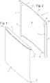
- Fig. 1 shows a perspective view of a door according to the invention, which can serve as a door of a refrigerator or freezer or as one of several doors of a combination refrigerator.
- the door comprises in known manner an outer wall 1, which is integrally formed from a sheet metal blank, an upper end element 2, a lower end element 3 and a in the view of Fig. 1 invisible inner wall.
- the outer wall 1 is in Fig. 2 to see in a perspective view, which essentially shows the hidden in the assembled state of the door inner surface of the outer wall 1.
- the outer wall is articulated in a slightly cambered front panel 4, two laterally adjoining the front panel 4 side edges 5 and two of the side edges 5 of the front panel 4 engaging behind edge webs 6.
- the edge webs 6 are each used to attach the rear wall, not shown. This is cut in a known per se and therefore not described in detail here manner of plastic sheet and formed by deep drawing.
- the outer wall 1 forms a respective hollow rib. 7
- a web 8 is angled in the horizontal direction in each case.
- the width of the web 8 is larger in each case in a central portion 9 than at its two ends 10.
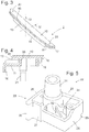
- Fig. 3 shows in the perspective of Fig. 1 the upper end element 2 of the door.
- Fig. 4 is a section through the upper end element 2 along a in Fig. 3 level designated IV-IV.
- the injection molded plastic end member 2 has a flat base plate 11 and one piece with this and related to her parallel second plate 12 which together defines a forwardly open groove 13.
- the second plate 12 carries a plurality of engaging in the groove 13, extending substantially in the depth direction of the groove 13 ribs 14.
- the second plate 12 is above a front edge 15 of the base plate 11 via.
- a vertically downwardly extending wall 16 is integrally formed on the front edge thereof.
- the groove 13 takes in the finished assembled state of the door, the upper of the two webs 8 of the outer wall 1, wherein the web 8 between the ribs 14 and the base plate 11 is clamped.
- the inside of the face plate 4 is supported on the wall 16. Since the wall 16 projects beyond the front edge 15 of the base plate 11, the front plate 4 resting against the wall 16 also does so, so that a door front which is easy to clean and free of protrusions or steps is obtained.
- Two angled lugs 17 projecting at the longitudinal ends of the end element 2 are provided to be in the assembled condition as in FIG Fig. 1 shown outside abut the side edges 5 and to fix their position.
- a vertically oriented groove 19 extending along a rear edge 18 of the base plate 11 is provided to receive and fix an upper edge of the inner wall.
- bearing bushes 21 Two in the Fig. 3 visible openings 20 of the base plate belong to bearing bushes 21, which are provided to rotatably receive a bearing journal, not shown, fixed to a housing carrying the door.
- the bushings 21 are in a conventional manner at each end element in mirror-symmetrical arrangement twice available to allow mounting of the door to the housing optionally with left or right stop.
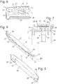
- Fig. 5 shows a perspective view of one of two mutually mirror-symmetrical stiffening elements 22, which are provided to be inverted in each case after the joining of the closing element 2 with the outer wall 1, but before the assembly of the inner wall, over the bearing bushes 21 of the closing element 2.
- the Stiffening element 22 has a base 23 whose shape is similar to a box open on one side, with an approximately quadrangular bottom plate 24 and adjoining the edges of the bottom plate 24 side walls 25 to 28.
- the bottom plate 24 contacts the base plate 11 of the end element 2
- the front side wall 25 nestles in extension of the wall 16 from the inside to the front panel 4, wherein a recess 29 at the foot of the side wall 25, the second plate 12 of the end element 2 receives.
- the outer side wall 26 abuts against the inside of one of the side flanks 5, and a part of the side wall 27 contacts one of the edge webs 6.
- a rib-shaped projection 30 between the side walls 26, 27 engages in each case in one of the hollow ribs 7 of the outer wall 1.
- a sleeve 31 of the stiffening element 22 encloses the bearing bush 21 essentially without play. In relation to the sleeve 31, radially oriented ribs 32 connect them to the side walls 26, 27, 28.
- the bearing bush 21 is reinforced, so that a resilient door suspension can be realized even with a relatively small wall thickness of the end element 2, the special benefit of the stiffening element 22, however, lies in the positive fixing of the front panel 4.
- the stiffening element 22nd positively engages between the front panel 4 and the edge webs 6, it prevents the front panel 4 from it to evade during foaming of the cavity formed by the outer wall 1, inner wall and end members 2, 3 while losing the grip in the groove 13.
- the lower end element 3 can, as in Fig. 1 indicated, mirror image formed to the upper end element 2.
- one of the four bushings 21 of the end members 2, 3 is open at its tip projecting into the cavity of the door to serve as an injection port for a synthetic resin material which is allowed to expand in the cavity to finally fill the cavity completely To get foam.
- the other three bushings 21, which are located at the furthest from the injection point corners of the interior, are then conveniently provided at their tip with a vent valve, which allows the escape of air, but not foam, from the cavity.
- Fig. 6 shows a horizontal section through a part of the door, wherein one of the stiffening elements 22 can be seen in plan view. It can be seen the sleeve 31, the outgoing from her ribs 32, the walls 25 to 28 and the closely to the walls 25, 26, 27 and the projection 30 fitted course of the outer wall 1.
- the tab 17 is in this embodiment, deviating from the presentation of the Fig. 3 extended rearwardly around the hollow rib 7 and merges into a rib 33 forming an outer boundary of the groove 19, here denoted 34, of the inner wall of the door.
- Fig. 7 shows a section through the closing element 2 and the stiffening element 22 mounted thereon in a plane to the Fig. 4 parallel plane.
- the base plate 11, a vertical wall 35 connecting the base plate 11 to the second plate 12 and a wall 45 of the closure element 2 delimiting the groove 19 form a recess into which the base 23 of the reinforcing element 22 engages in a form-fitting manner.
- the stiffening element 22 is fixed in the recess by the insulating foam.
- An additional, even during the assembly of the door effective fixation is formed by a recess or a window 36 in the wall 35 into which engages in the height of the recess 29 formed on the stiffening element 22 locking projection 37.
- Fig. 8 shows a second embodiment of the closure element, denoted by 2 ', in one of Fig. 3 appropriate perspective;
- Fig. 9 shows the back of the end element 2 'in one of Fig. 2 appropriate perspective.
- Corresponding parts of this end element 2 'and the closure element 2 described above are provided with the same reference numerals.
- a base plate 11 and a second plate 12 define a forwardly open groove 13 into which ribs 14 protrude to clamp an angled web 8 of the outer wall 1 therein.
- a vertical rear wall 38 is integrally formed on the base plate 11.
- a vertical rear wall 38 is integrally formed in the rear wall 38 and the base plate 11 to the rear and upwardly open recesses 39 , which are provided to a not shown, from the body of the refrigerator to receive projecting arm, which carries at its end a bearing in an opening 20 at the bottom of the recess 39 bearing journal, and to hide the arm in front of the eyes of an observer in front of the device.
- the opening 20 belongs to a bearing bushing 21 projecting into the interior of the door.
- Fig. 10 shows a perspective view from below of a part of the closing element 2 ', each with one of the recesses 39 and the bearing bushes 21 and a part of the attached to the closing element 2' outer wall 1.
- the outer wall 1 at the End element 2 'anchored by the (in Fig. 10 covered) web 8 of the outer wall 1 in the groove 13 of the end element 2 ' engages.
- a wall 45 of the end element 2 ' which bounds the inner wall 34 (not shown) receiving groove 19, engages behind a short piece of the edge web 6 of the outer wall 1.
- a definitive anchorage is obtained by placing an in Fig. 10 separated from the outer wall 1 and the end element 2 'shown stiffening element 22' on the bearing bush 21 of the end element 2 'is pushed.
- the structure of the stiffening element 22 ' largely compensates for the stiffening element 22 Fig. 5 , with the difference that in the stiffening element 22 two tongues 41, 42 protrude beyond the bottom plate of the base 23 to each in the assembled state in a gap between the walls of the recess 39 and the side edge 5 and the front plate 4 of the outer wall. 1 intervene.
- Fig. 11 shows a section through the tongue 42 engaging in a gap 43 between a recess 39 delimiting wall 44 and the front plate 4 supporting Wall 16.
- a latching projection 37 which engages in a recess of the wall 16, the stiffening element 22 'is inextricably connected to the end element 2'.
Landscapes
- Engineering & Computer Science (AREA)
- Chemical & Material Sciences (AREA)
- Combustion & Propulsion (AREA)
- Physics & Mathematics (AREA)
- Mechanical Engineering (AREA)
- Thermal Sciences (AREA)
- General Engineering & Computer Science (AREA)
- Refrigerator Housings (AREA)
- Hinges (AREA)
- Devices That Are Associated With Refrigeration Equipment (AREA)
Description
- Die vorliegende Erfindung betrifft ein Haushaltsgerät, insbesondere ein Kühl- oder Gefriergerät, mit einer Tür die mit einer Außenwand und einer Innenwand ausgestattet ist, die entlang von Längsrändern miteinander verbunden sind, und wenigstens einem Abschlusselement, das jeweils mit einem Querrand der Außenwand bzw. der Innenwand verbunden ist. Ein Haushaltsgerät mit einer solchen Tür ist zum Beispiel aus
DE 103 02 797A1 und ausDE 102 59 749A1 bekannt. Ein Haushaltsgerät gemäß dem Oberbegriff des Anspruchs 1 ist ausUS 6,209,265 B1 bekannt. - Üblicherweise sind an den Abschlusselementen Türlagerbuchsen ausgeformt, die vorgesehen sind, um fest mit dem Korpus des Gerätes verbundene Lagerzapfen aufzunehmen und so die Tür drehbar mit dem Korpus zu verbinden. Diese Lagerzapfen tragen im Betrieb das Gewicht der Tür und können bei der Montage der Tür erheblichen Drehmomenten ausgesetzt sein, so dass auch die Lagerbuchsen dementsprechend hoch belastbar sein müssen. Die Wandstärke der Abschlusselemente darf daher in der Umgebung der Lagerbuchsen nicht zu knapp bemessen sein. Um zu verhindern, dass sich die zumeist aus Kunststoff spritzgeformten Abschlusselemente beim Entformen verziehen, ist es andererseits wünschenswert, dass die Wandstärke der Abschlusselemente von Ort zu Ort möglichst wenig variiert. Dies macht die Fertigung der Abschlusselemente materialaufwändig und dementsprechend teuer.
- Die Aufgabe der vorliegenden Erfindung ist, ein Haushaltsgerät mit einer aus Außenwand, Innenwand und wenigstens einem Abschlusselement zusammengefügten Tür anzugeben, bei der das Abschlusselement leicht und materialsparend ausgeführt sein kann und dennoch eine hohe Belastbarkeit der Tür erreicht wird.
- Die Aufgabe wird gelöst, indem bei einem Haushaltsgerät mit einer Tür, die mit einer Außenwand und einer Innenwand versehen ist, die entlang von Längsrändern miteinander verbunden sind, und wenigstens einem Abschlusselement, das jeweils mit einem Querrand der Außenwand bzw. der Innenwand verbunden ist und eine Öffnung zur Aufnahme eines Scharnierzapfens aufweist, an einer Innenseite des Abschlusselementes eine Hülse befestigt ist, von der ein innerer Hohlraum hinter der Öffnung liegt.
- An dem Abschlusselement ist eine Türlagerbuchse angeformt, die in den Hohlraum der Hülse eingreift. Aufgrund der Stabilisierung durch die Hülse ist es möglich, die Wandstärke des Abschlusselementes im Vergleich zu einem nicht durch eine Hülse stabilisierten Abschlusselement zu verringern und dennoch die gleiche Belastbarkeit zu erreichen.
- Die Türlagerbuchse kann als Einspritzöffnung zum Einspritzen von Isolationsmaterial in einen inneren Hohlraum der Tür dienen.
- Alternativ kann in der Türlagerbuchse ein Entlüftungsventil untergebracht sein, durch das Luft aus dem inneren Hohlraum entweichen kann, wenn in diesem eingespritztes Isolationsmaterial expandiert.
- In der Praxis sind im Allgemeinen mehrere Türlagerbuchsen an einer Tür vorhanden, so dass zweckmäßigerweise eine als Einspritzöffnung dienen kann und die übrigen mit einem Entlüftungsventil versehen sind.
- Um die Versteifungswirkung der Hülse zu verbessern, ist diese vorzugsweise Teil eines Versteifungselementes, von dem eine Bodenplatte an dem Abschlusselement anliegt.
- Eine zusätzliche Versteifung kann dadurch erzielt werden, dass die Bodenplatte durch eine Wand berandet ist, die an der Außenwand oder der Innenwand der Tür anliegt.
- Die Hülse kann auch Teil eines Versteifungselementes sein, von dem eine Basis in eine Aussparung des Abschlusselementes eingesteckt ist.
- Um die Hülse in ihrer Position zu sichern, ist die Basis zweckmäßigerweise in der Aussparung verrastet.
- Bei den eingangs genannten herkömmlichen Türen stehen die Abschlusselemente geringfügig über die Außenwand über, so dass jeweils Querränder der Außenwand in Nuten der Abschlusselemente eingesteckt werden können. Dies macht die Abschlusselemente recht auffällig. Um sie unauffälliger zu machen, trägt die Außenwand entlang wenigstens eines ihrer Querränder einen zur Innenwand hin abgewinkelten Steg, und das Abschlusselement weist eine zur Außenseite der Tür hin offene Nut auf, in die der Steg eingreift. Während also bei den herkömmlichen Türen ein in die Nut des Abschlusselementes eingreifender Randbereich der Außenwand mit dem Rest der Außenwand bündig ist, und eine den Randbereich aufnehmende Nut zwangsläufig eine Seitenwand haben muss, die über die Außenwand übersteht, wird erfindungsgemäß dadurch, dass der abgewinkelte Steg den in die Nut eingreifenden Randbereich bildet, die Möglichkeit geschaffen, das Abschlusselement hinter die Frontseite zurücktreten zu lassen, wodurch das Abschlusselement vor den Augen eines Betrachters weitgehend verborgen ist und eine von eventuell Schmutz sammelnden Stufen freie Frontseite erhalten werden kann.
- Um einerseits den Steg in der Nut festklemmen zu können, andererseits aber zu verhindern, dass eine allzu hohe Kraft erforderlich wird, um den Steg in die Nut einzuführen, ist die Nut vorzugsweise breiter als der darin eingreifende Steg, und der Steg ist an von einer Seitenwand der Nut abstehenden Rippen geklemmt.
- In an sich bekannter Weise bildet vorzugsweise die Außenwand eine Frontplatte und zwei an die Frontplatte angrenzende Seitenflanken der Tür.
- Wenn darüber hinaus die Außenwand ferner zwei von den Seitenflanken aus die Frontplatte hintergreifende Randstege umfasst, so ist die Länge einer die Frontplatte abstützenden Wand des Abschlusselementes vorzugsweise kleiner als der Abstand der Randstege voneinander, um das Einführen des abgewinkelten Steges in die Nut des Abschlusselementes nicht zu behindern.
- Das Abschlusselement ist zur Fixierung der Außenwand ferner vorzugsweise mit zwei außen an den Seitenflanken anliegenden Laschen versehen.
- Das bereits erwähnte Versteifungselement kann auch zur Fixierung der Außenwand beitragen. So kann zum einen die Seitenflanke der Außenwand zwischen dem Versteifungselement und der Lasche fixiert sein. Zum anderen kann das Versteifungselement einen Anschlag bilden, an dem jeweils eine der Seitenflanken anliegt.
- Besonders bevorzugt ist zur Fixierung der Außenwand, dass diese zwischen Seitenflanke und Randsteg jeweils eine hohle Rippe bildet und dass das Versteifungselement einen in den Hohlraum der Rippe eingreifenden Vorsprung aufweist.
- Um den Zusammenbau der Tür zu vereinfachen, ist das Versteifungselement vorzugsweise an dem Abschlusselement verrastet.
- Weitere Merkmale und Vorteile der Erfindung ergeben sich aus der nachfolgenden Beschreibung von Ausführungsbeispielen unter Bezugnahme auf die beigefügten Figuren. Es zeigen:
- Fig. 1
- eine perspektivische Ansicht einer erfindungsgemäßen Tür;
- Fig. 2
- eine perspektivische Ansicht der Außenwand der Tür;
- Fig. 3
- ein Abschlusselement der Tür aus
Fig. 1 ; - Fig. 4
- einen Schnitt durch das Abschlusselement der
Fig. 3 ; - Fig. 5
- eine perspektivische Ansicht eines Versteifungselementes;
- Fig. 6
- einen horizontalen Schnitt durch die Tür, der das Versteifungselement in einer Draufsicht zeigt;
- Fig. 7
- einen Schnitt durch das Abschlusselement in einer Schnittebene parallel zu derjenigen der
Fig. 4 ; - Fig. 8
- eine perspektivische Ansicht von vorn eines Abschlusselementes gemäß einer zweiten Ausgestaltung;
- Fig. 9
- eine perspektivische Ansicht von hinten des Abschlusselements aus
Fig. 8 ; - Fig. 10
- eine fragmentarische perspektivische Ansicht des Abschlusselementes der
Fig. 8 , einer daran montierten Außenwand und eines daran zu montierenden Versteifungselementes, und - Fig. 11
- einen Teilschnitt durch das Abschlusselement, die Außenwand und das Versteifungselement der
Fig. 10 im zusammengefügten Zustand. -
Fig. 1 zeigt in perspektivischer Ansicht eine erfindungsgemäße Tür, die als Tür eines Kühl- oder Gefrierschrankes oder als eine von mehreren Türen eines Kombinations-Kältegerätes dienen kann. Die Tür umfasst in an sich bekannter Weise eine Außenwand 1, die aus einem Blechzuschnitt einstückig geformt ist, ein oberes Abschlusselement 2, ein unteres Abschlusselement 3 und eine in der Ansicht derFig. 1 nicht sichtbare Innenwand. - Die Außenwand 1 ist in
Fig. 2 in einer perspektivischen Ansicht zu sehen, die im Wesentlichen die im montierten Zustand der Tür verborgene Innenfläche der Außenwand 1 zeigt. Die Außenwand ist gegliedert in eine leicht bombierte Frontplatte 4, zwei jeweils seitlich an die Frontplatte 4 anschließende Seitenflanken 5 und zwei von den Seitenflanken 5 aus die Frontplatte 4 hintergreifende Randstege 6. Die Randstege 6 dienen jeweils zur Befestigung der nicht gezeigten Rückwand. Diese ist in an sich bekannter und daher hier nicht im Detail beschriebener Weise aus Kunststoff-Flachmaterial zugeschnitten und durch Tiefziehen geformt. - Zwischen den Seitenflanken 5 und den Randstegen 6 bildet die Außenwand 1 jeweils eine hohle Rippe 7.
- An den oberen und unteren Rändern der Außenwand 1 ist jeweils ein Steg 8 in horizontaler Richtung abgewinkelt. Die Breite des Steges 8 ist jeweils in einem mittleren Abschnitt 9 größer als an seinen beiden Enden 10.
-
Fig. 3 zeigt in der Perspektive derFig. 1 das obere Abschlusselement 2 der Tür.Fig. 4 ist ein Schnitt durch das obere Abschlusselement 2 entlang einer inFig. 3 mit IV-IV bezeichneten Ebene. Das aus Kunststoff spritzgeformte Abschlusselement 2 hat eine flache Grundplatte 11 und eine mit dieser einteilig zusammenhängende und zu ihr parallele zweite Platte 12, die zusammen eine nach vorn offene Nut 13 begrenzt. Die zweite Platte 12 trägt eine Mehrzahl von in die Nut 13 eingreifenden, sich im Wesentlichen in Tiefenrichtung der Nut 13 erstreckenden Rippen 14. Die zweite Platte 12 steht über einen vorderen Rand 15 der Grundplatte 11 über. In einem mittleren Bereich der zweiten Platte 12 ist an deren vorderen Rand eine sich vertikal nach unten erstreckende Wand 16 angeformt. - Die Nut 13 nimmt im fertig montierten Zustand der Tür den oberen der beiden Stege 8 der Außenwand 1 auf, wobei der Steg 8 zwischen den Rippen 14 und der Grundplatte 11 geklemmt wird. Wenn der Steg 8 ordnungsgemäß in die Nut 13 eingeführt ist, ist die Innenseite der Frontplatte 4 an der Wand 16 abgestützt. Da die Wand 16 über den vorderen Rand 15 der Grundplatte 11 übersteht, tut die an der Wand 16 anliegende Frontplatte 4 dies auch, so dass eine reinigungsfreundliche, von Vorsprüngen oder Stufen freie Türvorderseite erhalten wird.
- Zwei an den Längsenden des Abschlusselementes 2 abstehende, gewinkelte Laschen 17 sind vorgesehen, um im zusammengebauten Zustand wie in
Fig. 1 gezeigt außen an den Seitenflanken 5 anzuliegen und deren Stellung zu fixieren. - Eine sich entlang eines rückwärtigen Randes 18 der Grundplatte 11 erstreckende vertikal orientierte Nut 19 ist vorgesehen, um einen oberen Rand der Innenwand aufzunehmen und zu fixieren.
- Zwei in der
Fig. 3 sichtbare Öffnungen 20 der Grundplatte gehören zu Lagerbuchsen 21, die vorgesehen sind, um einen nicht dargestellten, an einem die Tür tragenden Gehäuse festen Lagerzapfen drehbar aufzunehmen. Die Lagerbuchsen 21 sind in an sich bekannter Weise an jedem Abschlusselement in spiegelsymmetrischer Anordnung zweimal vorhanden, um eine Montage der Tür an dem Gehäuse wahlweise mit Links- oder mit Rechtsanschlag zu ermöglichen. -
Fig. 5 zeigt in perspektivischer Ansicht eines von zwei zueinander spiegelsymmetrischen Versteifungselementen 22, die vorgesehen sind, um jeweils nach dem Zusammenfügen des Abschlusselementes 2 mit der Außenwand 1, aber vor der Montage der Innenwand, über die Lagerbuchsen 21 des Abschlusselementes 2 gestülpt zu werden. Das Versteifungselement 22 hat eine Basis 23, deren Gestalt einem einseitig offenen Kasten ähnelt, mit einer in etwa viereckigen Bodenplatte 24 und an die Ränder der Bodenplatte 24 anschließenden Seitenwänden 25 bis 28. Im zusammengebauten Zustand berührt die Bodenplatte 24 die Grundplatte 11 des Abschlusselementes 2, die vordere Seitenwand 25 schmiegt sich in Verlängerung der Wand 16 von innen an die Frontplatte 4 an, wobei eine Aussparung 29 am Fuß der Seitenwand 25 die zweite Platte 12 des Abschlusselementes 2 aufnimmt. Die äußere Seitenwand 26 liegt an der Innenseite einer der Seitenflanken 5 an, und ein Teil der Seitenwand 27 berührt einen der Randstege 6. Ein rippenförmiger Vorsprung 30 zwischen den Seitenwänden 26, 27 greift jeweils in eine der hohlen Rippen 7 der Außenwand 1 ein. Eine Hülse 31 des Versteifungselementes 22 umschließt im Wesentlichen spielfrei die Lagerbuchse 21. In Bezug auf die Hülse 31 radial orientierte Rippen 32 verbinden diese mit den Seitenwänden 26, 27, 28. - Durch die Anbringung des Versteifungselementes 22 ist einerseits die Lagerbuchse 21 verstärkt, so dass eine belastbare Türaufhängung auch mit einer relativ geringen Wandstärke des Abschlusselementes 2 realisierbar ist, der besondere Nutzen des Versteifungselementes 22 liegt allerdings in der formschlüssigen Fixierung der Frontplatte 4. Indem das Versteifungselement 22 formschlüssig zwischen die Frontplatte 4 und die Randstege 6 eingreift, hindert es die Frontplatte 4 daran, beim Ausschäumen des von Außenwand 1, Innenwand und Abschlusselementen 2, 3 gebildeten Hohlraumes nach vorn auszuweichen und dabei den Halt in der Nut 13 zu verlieren.
- Das untere Abschlusselement 3 kann, wie in
Fig. 1 angedeutet, spiegelbildlich zu dem oberen Abschlusselement 2 ausgebildet sein. In diesem Fall ist vorzugsweise eine der vier Lagerbuchsen 21 der Abschlusselemente 2, 3 an ihrer in den Hohlraum der Tür hineinragenden Spitze offen, um als Einspritzöffnung für ein Kunstharzmaterial zu dienen, das in dem Hohlraum expandieren gelassen wird, um schließlich einen den Hohlraum vollständig ausfüllenden Schaum zu erhalten. Die anderen drei Lagerbuchsen 21, die sich an den am weitesten von der Einspritzstelle entfernten Ecken des Innenraumes befinden, sind dann zweckmäßigerweise an ihrer Spitze jeweils mit einem Entlüftungsventil versehen, welches das Entweichen von Luft, nicht aber von Schaum, aus dem Hohlraum gestattet. -
Fig. 6 zeigt einen horizontalen Schnitt durch einen Teil der Tür, wobei eines der Versteifungselemente 22 in Draufsicht zu sehen ist. Man erkennt die Hülse 31, die von ihr ausgehenden Rippen 32, die Wände 25 bis 28 sowie den eng an die Wände 25, 26, 27 und den Vorsprung 30 angeschmiegten Verlauf der Außenwand 1. Die Lasche 17 ist bei dieser Ausgestaltung, abweichend von der Darstellung derFig. 3 , nach hinten um die hohle Rippe 7 herum verlängert und geht über in eine Rippe 33, die eine äußere Begrenzung der die hier mit 34 bezeichnete Innenwand der Tür aufnehmenden Nut 19 bildet. -
Fig. 7 zeigt einen Schnitt durch das Abschlusselement 2 und das daran montierte Versteifungselement 22 in einer zur Ebene derFig. 4 parallelen Ebene. In dieser Ebene bilden die Grundplatte 11, eine die Grundplatte 11 mit der zweiten Platte 12 verbindende vertikale Wand 35 und eine die Nut 19 begrenzende Wand 45 des Abschlusselementes 2 eine Aussparung, in die die Basis 23 des Versteifungselements 22 formschlüssig eingreift. Wenn die Tür fertig zusammengefügt und ausgeschäumt ist, ist das Versteifungselement 22 in der Aussparung durch den Isolierschaum fixiert. Eine zusätzliche, auch während des Zusammenbaus der Tür wirksame Fixierung wird durch eine Vertiefung oder ein Fenster 36 in der Wand 35 gebildet, in das ein in Höhe der Aussparung 29 an dem Versteifungselement 22 geformter Rastvorsprung 37 eingreift. Durch diesen Rastvorsprung 37 ist das Versteifungselement 22, wenn es einmal an dem Abschlusselement 2 montiert ist, unlösbar mit diesem verbunden. -
Fig. 8 zeigt eine zweite Ausgestaltung des Abschlusselementes, mit 2' bezeichnet, in einer derFig. 3 entsprechenden Perspektive;Fig. 9 zeigt die Rückseite des Abschlusselementes 2' in einer derFig. 2 entsprechenden Perspektive. Einander entsprechende Teile dieses Abschlusselements 2' und des oben beschriebenen Abschlusselementes 2 sind mit den gleichen Bezugszeichen versehen. Wie bei dem Abschlusselement 2 begrenzen eine Grundplatte 11 und eine zweite Platte 12 eine nach vorn offene Nut 13, in die Rippen 14 vorspringen, um darin einen abgewinkelten Steg 8 der Außenwand 1 zu klemmen. - An die Grundplatte 11 ist eine vertikale Rückwand 38 angeformt. In der Rückwand 38 und der Grundplatte 11 sind nach hinten und nach oben offene Ausnehmungen 39 gebildet, die vorgesehen sind, um einen nicht dargestellten, vom Korpus des Kältegerätes abstehenden Arm aufzunehmen, der an seinem Ende einen in eine Öffnung 20 am Boden der Ausnehmung 39 eingreifenden Lagerzapfen trägt, und den Arm so vor den Blicken eines vor dem Gerät stehenden Betrachters zu verbergen. Wie beim Abschlusselement 2 gehört die Öffnung 20 zu einer ins Innere der Tür vorspringenden Lagerbuchse 21.
-
Fig. 10 zeigt eine perspektivische Ansicht von unten eines Teiles des Abschlusselementes 2' mit jeweils einer der Ausnehmungen 39 und der Lagerbuchsen 21 sowie eines Teiles der an dem Abschlusselement 2' befestigten Außenwand 1. Wie mit Bezug auf das Abschlusselement 2 beschrieben, ist die Außenwand 1 an dem Abschlusselement 2' verankert, indem der (inFig. 10 verdeckte) Steg 8 der Außenwand 1 in die Nut 13 des Abschlusselementes 2' eingreift. Im Gegensatz zum Abschlusselement 2 ist hier jedoch eine Wand 45 des Abschlusselementes 2', die die Innenwand 34 (nicht dargestellt) aufnehmende Nut 19 begrenzt, auf einem kurzen Stück von dem Randsteg 6 der Außenwand 1 hintergriffen. Es ist daher nicht möglich, das Abschlusselement 2' und die Außenwand 1 zusammenzufügen, indem lediglich beide horizontal gegeneinander geschoben und dabei der Steg 8 in die Nut 13 eingeführt wird; stattdessen muss beim Einschieben des Steges 8 in die Rippe 13 das Abschlusselement 2' etwas schräg gehalten sein, so dass der Randsteg 6 die Wand 45 passieren kann, und erst nach Passieren dieser Wand 45 wird das Abschlusselement 2' um eine horizontale Achse 40 (sieheFig. 8 ) geschwenkt, so dass ein Ende des Randsteges 6 an der Wand 45 zur Anlage kommt, wie inFig. 10 gezeigt. Auf diese Weise wird eine erste, provisorische Verankerung der Außenwand 1 an dem Abschlusselement 2' erhalten. - Eine definitive Verankerung wird erhalten, indem ein in
Fig. 10 getrennt von der Außenwand 1 und dem Abschlusselement 2' dargestelltes Versteifungselement 22' auf die Lagerbuchse 21 des Abschlusselementes 2' aufgeschoben wird. Der Aufbau des Versteifungselementes 22' gleicht weitgehend dem des Versteifungselementes 22 ausFig. 5 , mit dem Unterschied, dass bei dem Versteifungselement 22 zwei Zungen 41, 42 über die Bodenplatte der Basis 23 hinaus überstehen, um im montierten Zustand jeweils in einen Spalt zwischen den Wänden der Ausnehmung 39 und der Seitenflanke 5 bzw. der Frontplatte 4 der Außenwand 1 einzugreifen. -
Fig. 11 zeigt einen Schnitt durch die Zunge 42 eingreifend in einen Spalt 43 zwischen einer die Aussparung 39 begrenzenden Wand 44 und der die Frontplatte 4 abstützenden Wand 16. Durch einen Rastvorsprung 37, der in eine Aussparung der Wand 16 eingreift, ist das Versteifungselement 22' unlösbar mit dem Abschlusselement 2' verbunden.
Claims (16)
- Haushaltsgerät, insbesondere Haushaltskältegerät mit einer wärmeisolierten Tür, die eine Außenwand (1) und eine Innenwand (34) aufweist, die entlang von Längsrändern miteinander verbunden sind und einen zur Wärmeisolation der Tür dienenden Zwischenraum begrenzen, und wenigstens ein Abschlusselement (2, 3; 2'), das jeweils mit einem Querrand der Außenwand (1) bzw. der Innenwand (34) verbunden ist und eine Öffnung (20) zur Aufnahme eines Scharnierzapfens aufweist, wobei an einer Innenseite des Abschlusselements (2, 3; 2') eine Hülse (31) befestigt ist, von der ein innerer Hohlraum zum Zwischenraum hin der Öffnung (20) nachgelagert ist, dadurch gekennzeichnet, dass die Öffnung (20) Eingang einer an das Abschlusselement (2, 3; 2') angeformten, in den Hohlraum der Hülse (31) eingreifenden Türlagerbuchse (21) ist und die Außenwand (1) entlang wenigstens eines der Querränder einen zur Innenwand (34) hin abgewinkelten Steg (8) trägt, und dass das Abschlusselement (2; 2') eine zur Außenseite der Tür hin offene Nut (13) aufweist, in die der Steg (8) eingreift.
- Haushaltsgerät nach Anspruch 1, dadurch gekennzeichnet, dass die Türlagerbuchse (21) als Einspritzöffnung zum Einspritzen von Isolationsmaterial in einen inneren Hohlraum der Tür dient.
- Haushaltsgerät nach Anspruch 1, dadurch gekennzeichnet, dass in der Türlagerbuchse (21) ein Entlüftungsventil zum Entlüften eines inneren Hohlraums der Tür untergebracht ist.
- Haushaltsgerät nach einem der vorhergehenden Ansprüche, dadurch gekennzeichnet, dass die Hülse (31) Teil eines Versteifungselements (22, 22') mit einer Bodenplatte (24) ist, wobei die Bodenplatte (24) an dem Abschlusselement (2) anliegt.
- Haushaltsgerät nach Anspruch 4, dadurch gekennzeichnet, dass die Bodenplatte (24) durch eine an der Außenwand (1) und/oder der Innenwand (34) anliegende Wand (25, 26, 27) berandet ist.
- Haushaltsgerät nach einem der Ansprüche 1 bis 3, dadurch gekennzeichnet, dass die Hülse (31) Teil eines Versteifungselements (22, 22') mit einer Basis (23) ist, wobei die Basis (23) in einer Aussparung des Abschlusselements eingesteckt ist.
- Haushaltsgerät nach Anspruch 6, dadurch gekennzeichnet, dass die Basis (23) in der Aussparung verrastet ist.
- Haushaltsgerät nach einem der vorhergehenden Ansprüche, dadurch gekennzeichnet, dass die Nut (13) breiter ist als der darin eingreifende Steg (8) und dass der Steg (8) an von einer Seitenwand (12) der Nut abstehenden Rippen (14) geklemmt ist.
- Haushaltsgerät nach einem der vorhergehenden Ansprüche, dadurch gekennzeichnet, dass die Außenwand (1) eine Frontplatte (4) und zwei an die Frontplatte (4) angrenzende Seitenflanken (5) der Tür bildet.
- Haushaltsgerät nach Anspruch 9, dadurch gekennzeichnet, dass die Außenwand (1) ferner zwei von den Seitenflanken (5) aus die Frontplatte (4) hintergreifende Randstege (6) umfasst.
- Haushaltsgerät nach Anspruch 10, dadurch gekennzeichnet, dass das Abschlusselement (2; 2') eine die Frontplatte (4) abstützende Wand (16) trägt, deren Länge kleiner ist als der Abstand der Randstege (6) voneinander.
- Haushaltsgerät nach Anspruch 9, 10 oder 11, dadurch gekennzeichnet, dass ein vorderer Rand (15) des Abschlusselements (2) hinter die Frontseite der Tür zurückspringt.
- Haushaltsgerät nach einem der Ansprüche 9 bis 12, dadurch gekennzeichnet, dass das Abschlusselement (2; 2') zwei außen an den Seitenflanken (5) anliegende Laschen (17) trägt.
- Haushaltsgerät nach Anspruch 13, dadurch gekennzeichnet, dass die Hülse (31) Teil eines Versteifungselements (22) ist und dass die Seitenflanke (5) zwischen dem Versteifungselement (22) und der Lasche (17) fixiert ist.
- Haushaltsgerät nach Anspruch 10 und Anspruch 14, dadurch gekennzeichnet, dass das Versteifungselement (22) einen Anschlag für einen der Randstege (6) bildet.
- Haushaltsgerät nach Anspruch 10 und Anspruch 14, dadurch gekennzeichnet, dass die Außenwand (1) zwischen Seitenflanke (5) und Randsteg (6) jeweils eine hohle Rippe (7) bildet und dass das Versteifungselement (22) einen in den Hohlraum der Rippe (7) eingreifenden Vorsprung (30) aufweist.
Priority Applications (1)
| Application Number | Priority Date | Filing Date | Title |
|---|---|---|---|
| PL08759597T PL2153147T3 (pl) | 2007-05-23 | 2008-05-14 | Urządzenie gospodarstwa domowego |
Applications Claiming Priority (2)
| Application Number | Priority Date | Filing Date | Title |
|---|---|---|---|
| DE202007007320U DE202007007320U1 (de) | 2007-05-23 | 2007-05-23 | Haushaltsgerät |
| PCT/EP2008/055917 WO2008141993A2 (de) | 2007-05-23 | 2008-05-14 | Haushaltsgerät |
Publications (2)
| Publication Number | Publication Date |
|---|---|
| EP2153147A2 EP2153147A2 (de) | 2010-02-17 |
| EP2153147B1 true EP2153147B1 (de) | 2019-03-06 |
Family
ID=38320462
Family Applications (1)
| Application Number | Title | Priority Date | Filing Date |
|---|---|---|---|
| EP08759597.1A Active EP2153147B1 (de) | 2007-05-23 | 2008-05-14 | Haushaltsgerät |
Country Status (8)
| Country | Link |
|---|---|
| US (1) | US20100156260A1 (de) |
| EP (1) | EP2153147B1 (de) |
| CN (1) | CN101680704B (de) |
| DE (1) | DE202007007320U1 (de) |
| PL (1) | PL2153147T3 (de) |
| RU (1) | RU2009144904A (de) |
| TR (1) | TR201904447T4 (de) |
| WO (1) | WO2008141993A2 (de) |
Families Citing this family (21)
| Publication number | Priority date | Publication date | Assignee | Title |
|---|---|---|---|---|
| DE102007052081B4 (de) * | 2007-10-31 | 2016-07-21 | BSH Hausgeräte GmbH | Haushaltsgerät |
| DE102008041479A1 (de) * | 2008-08-22 | 2010-02-25 | BSH Bosch und Siemens Hausgeräte GmbH | Tür für ein Haushaltsgerät |
| BRPI0902918A2 (pt) * | 2009-08-17 | 2011-05-10 | Whirlpool Sa | capa de extremidade para porta de refrigerador |
| KR101897275B1 (ko) * | 2011-05-04 | 2018-09-11 | 엘지전자 주식회사 | 냉장고 및 냉장고 도어 |
| KR20120140392A (ko) * | 2011-06-21 | 2012-12-31 | 삼성전자주식회사 | 냉장고 |
| US10808993B2 (en) * | 2014-01-07 | 2020-10-20 | Samsung Electronics Co., Ltd. | Refrigerator |
| KR20160057105A (ko) * | 2014-11-13 | 2016-05-23 | 동부대우전자 주식회사 | 냉장고 및 냉장고 도어의 제조방법 |
| KR101586588B1 (ko) * | 2014-11-14 | 2016-02-02 | 동부대우전자 주식회사 | 냉장고 및 그 제조방법 |
| US9435579B1 (en) | 2015-04-10 | 2016-09-06 | Electrolux Home Products, Inc. | Insulated door assembly |
| JP6265950B2 (ja) * | 2015-07-31 | 2018-01-24 | 三菱電機エンジニアリング株式会社 | 保存庫 |
| KR101728730B1 (ko) | 2015-09-23 | 2017-04-20 | 엘지전자 주식회사 | 냉장고 |
| KR101858236B1 (ko) * | 2016-05-31 | 2018-05-16 | 주식회사 대우전자 | 냉장고 및 이를 제조하는 방법 |
| USD952703S1 (en) * | 2019-08-08 | 2022-05-24 | Samsung Electronics Co., Ltd. | Panel for refrigerator |
| USD952706S1 (en) * | 2019-08-08 | 2022-05-24 | Samsung Electronics Co., Ltd. | Panel for refrigerator |
| USD952705S1 (en) * | 2019-08-08 | 2022-05-24 | Samsung Electronics Co., Ltd. | Panel for refrigerator |
| USD952708S1 (en) * | 2019-08-08 | 2022-05-24 | Samsung Electronics Co., Ltd. | Panel for refrigerator |
| USD952707S1 (en) * | 2019-08-08 | 2022-05-24 | Samsung Electronics Co., Ltd. | Panel for refrigerator |
| USD952709S1 (en) * | 2019-08-08 | 2022-05-24 | Samsung Electronics Co., Ltd. | Panel for refrigerator |
| USD952704S1 (en) * | 2019-08-08 | 2022-05-24 | Samsung Electronics Co., Ltd. | Panel for refrigerator |
| USD951308S1 (en) * | 2019-08-08 | 2022-05-10 | Samsung Electronics Co., Ltd. | Panel for refrigerator |
| DE102021203158A1 (de) * | 2021-03-30 | 2022-10-06 | BSH Hausgeräte GmbH | Tür für ein Haushaltskältegerät mit spezifischer oberer Abschlussleiste, sowie Haushaltskältegerät |
Citations (2)
| Publication number | Priority date | Publication date | Assignee | Title |
|---|---|---|---|---|
| US6209265B1 (en) * | 1999-05-27 | 2001-04-03 | Camco Inc. | Refrigerator door corner construction |
| US20050194874A1 (en) * | 2004-03-05 | 2005-09-08 | Samsung Electronics, Co., Ltd. | Refrigerator |
Family Cites Families (24)
| Publication number | Priority date | Publication date | Assignee | Title |
|---|---|---|---|---|
| US3132382A (en) * | 1962-09-13 | 1964-05-12 | Gen Electric | Resin foam insulated cabinet |
| SE426873B (sv) * | 1981-06-30 | 1983-02-14 | Electrolux Sarl | Kylskapsdorr med en ram av hopfogade delar |
| JPS5976981U (ja) * | 1982-11-15 | 1984-05-24 | 株式会社東芝 | 冷蔵庫の断熱扉 |
| JPH02115680A (ja) * | 1988-10-21 | 1990-04-27 | Mitsubishi Electric Corp | 冷蔵庫 |
| US4955675A (en) * | 1989-04-17 | 1990-09-11 | White Consolidated Industries, Inc. | Hinged panels with foamed-in-place insulation |
| IT219351Z2 (it) * | 1990-03-28 | 1993-02-22 | Eurodomestici Ind Riunite | Dispositivo atto a definire una sede per cerniera in un mobile o portello di un frigorifero, di un congelatore o similare |
| CN2097987U (zh) * | 1991-06-01 | 1992-03-04 | 甘振兴 | 双向式冰箱门 |
| KR970007468B1 (ko) * | 1993-11-30 | 1997-05-09 | 아남산업 주식회사 | 반도체 리이드 프레임 |
| JP3461021B2 (ja) * | 1994-02-03 | 2003-10-27 | 株式会社日立製作所 | 冷蔵庫 |
| JP3188126B2 (ja) * | 1995-02-10 | 2001-07-16 | 三洋電機株式会社 | 冷蔵庫の扉キャップ |
| US5568712A (en) * | 1995-03-21 | 1996-10-29 | General Electric Company | Refrigerator door construction |
| JPH10160332A (ja) * | 1996-11-26 | 1998-06-19 | Sanyo Electric Co Ltd | 冷蔵庫等の扉体 |
| US6272793B1 (en) * | 2000-01-04 | 2001-08-14 | George N. Davlantes | Height adjustable assembly for pet door |
| JP4045078B2 (ja) * | 2001-05-15 | 2008-02-13 | 日立アプライアンス株式会社 | 冷蔵庫の扉 |
| CA2350419C (en) * | 2001-06-14 | 2006-12-12 | Camco Inc. | Thermal and reinforced refrigerator door |
| DE20212002U1 (de) * | 2002-08-05 | 2002-09-26 | BSH Bosch und Siemens Hausgeräte GmbH, 81669 München | Kältegerätetür |
| DE10259749A1 (de) * | 2002-12-19 | 2004-07-08 | BSH Bosch und Siemens Hausgeräte GmbH | Kältegerät und Tür für ein Kältegerät |
| DE10302797B4 (de) * | 2003-01-24 | 2025-05-28 | BSH Hausgeräte GmbH | Tür für ein Kältegerät und Kältegerät, umfassend eine Tür |
| CN1598449A (zh) * | 2003-09-17 | 2005-03-23 | 沈仲山 | 门扉开关装置 |
| KR20050096335A (ko) * | 2004-03-30 | 2005-10-06 | 삼성전자주식회사 | 도어핸들이 구비된 냉장고 |
| US7886500B2 (en) * | 2005-05-27 | 2011-02-15 | Maytag Corporation | Refrigerator door with ratcheting end cap |
| US7770985B2 (en) * | 2006-02-15 | 2010-08-10 | Maytag Corporation | Kitchen appliance having floating glass panel |
| US20080174218A1 (en) * | 2007-01-19 | 2008-07-24 | Whirlpool Corporation | Method and apparatus for clinched door design |
| KR101424554B1 (ko) * | 2007-01-23 | 2014-07-31 | 삼성전자 주식회사 | 양방향 개폐 가능한 도어유닛 및 이를 포함하는 냉장고 |
-
2007
- 2007-05-23 DE DE202007007320U patent/DE202007007320U1/de not_active Expired - Lifetime
-
2008
- 2008-05-14 PL PL08759597T patent/PL2153147T3/pl unknown
- 2008-05-14 WO PCT/EP2008/055917 patent/WO2008141993A2/de not_active Ceased
- 2008-05-14 EP EP08759597.1A patent/EP2153147B1/de active Active
- 2008-05-14 CN CN200880017160XA patent/CN101680704B/zh active Active
- 2008-05-14 US US12/600,681 patent/US20100156260A1/en not_active Abandoned
- 2008-05-14 TR TR2019/04447T patent/TR201904447T4/tr unknown
- 2008-05-14 RU RU2009144904/21A patent/RU2009144904A/ru not_active Application Discontinuation
Patent Citations (2)
| Publication number | Priority date | Publication date | Assignee | Title |
|---|---|---|---|---|
| US6209265B1 (en) * | 1999-05-27 | 2001-04-03 | Camco Inc. | Refrigerator door corner construction |
| US20050194874A1 (en) * | 2004-03-05 | 2005-09-08 | Samsung Electronics, Co., Ltd. | Refrigerator |
Also Published As
| Publication number | Publication date |
|---|---|
| CN101680704A (zh) | 2010-03-24 |
| DE202007007320U1 (de) | 2007-07-26 |
| CN101680704B (zh) | 2013-02-06 |
| EP2153147A2 (de) | 2010-02-17 |
| WO2008141993A2 (de) | 2008-11-27 |
| PL2153147T3 (pl) | 2019-08-30 |
| US20100156260A1 (en) | 2010-06-24 |
| TR201904447T4 (tr) | 2019-05-21 |
| WO2008141993A3 (de) | 2009-03-05 |
| RU2009144904A (ru) | 2011-06-27 |
Similar Documents
| Publication | Publication Date | Title |
|---|---|---|
| EP2153147B1 (de) | Haushaltsgerät | |
| EP2153149B2 (de) | Haushaltsgerät | |
| EP2153148B1 (de) | Haushaltsgerät | |
| EP2274561B1 (de) | Haushaltsgerät | |
| WO2002081991A1 (de) | Abstellbehälter für kältegeräte | |
| EP1846709B1 (de) | Tür für ein kältegerät | |
| EP2746706B1 (de) | Kältegerät mit veränderbarem Türanschlag | |
| EP2281095A1 (de) | Scharnierelement und gehäuse für ein haushaltsgerät | |
| EP2163840B1 (de) | Haushaltskältegerät mit zumindest einer Tür | |
| DE102009028428A1 (de) | Kältegerät mit einem Einbauteil | |
| EP1926949B1 (de) | Gehäuse für ein haushaltsgerät | |
| EP1926953A1 (de) | Tür für ein haushaltsgerät | |
| EP1926956B1 (de) | Kältegerät | |
| EP2281159B1 (de) | Tür für ein haushaltsgerät | |
| EP4067792B1 (de) | Haushaltsgrossgerät in form eines kältegerätes | |
| EP2283195A1 (de) | Scharnierelement und gehäuse für ein haushaltsgerät | |
| DE19825979A1 (de) | Hausgerät, insbesondere Kühlgerät | |
| EP1529188B1 (de) | Kältegerät mit unterteiltem innenraum | |
| WO2011018342A2 (de) | Kältegerät | |
| DE102019216193A1 (de) | Haushaltsgerät mit einem Scharnier und Scharnier für ein Haushaltsgerät | |
| EP2561291A2 (de) | Türblatt, verfahren zum herstellen eines türblatts und kältegerät mit einem türblatt | |
| DE102008028585A1 (de) | Eis-/Flüssigkeitsspendernische | |
| DE102013216804A1 (de) | Haushaltsgerät mit einer Türblattlagerung | |
| DE102014206583A1 (de) | Haushaltsgerät mit einer an einer Außenseite einer Tür ausgebildeten Vertiefung zur Aufnahme eines Bauteils |
Legal Events
| Date | Code | Title | Description |
|---|---|---|---|
| PUAI | Public reference made under article 153(3) epc to a published international application that has entered the european phase |
Free format text: ORIGINAL CODE: 0009012 |
|
| 17P | Request for examination filed |
Effective date: 20091223 |
|
| AK | Designated contracting states |
Kind code of ref document: A2 Designated state(s): AT BE BG CH CY CZ DE DK EE ES FI FR GB GR HR HU IE IS IT LI LT LU LV MC MT NL NO PL PT RO SE SI SK TR |
|
| AX | Request for extension of the european patent |
Extension state: AL BA MK RS |
|
| DAX | Request for extension of the european patent (deleted) | ||
| RAP1 | Party data changed (applicant data changed or rights of an application transferred) |
Owner name: BSH HAUSGERAETE GMBH |
|
| 17Q | First examination report despatched |
Effective date: 20160419 |
|
| STAA | Information on the status of an ep patent application or granted ep patent |
Free format text: STATUS: EXAMINATION IS IN PROGRESS |
|
| GRAP | Despatch of communication of intention to grant a patent |
Free format text: ORIGINAL CODE: EPIDOSNIGR1 |
|
| STAA | Information on the status of an ep patent application or granted ep patent |
Free format text: STATUS: GRANT OF PATENT IS INTENDED |
|
| INTG | Intention to grant announced |
Effective date: 20181008 |
|
| GRAS | Grant fee paid |
Free format text: ORIGINAL CODE: EPIDOSNIGR3 |
|
| GRAA | (expected) grant |
Free format text: ORIGINAL CODE: 0009210 |
|
| STAA | Information on the status of an ep patent application or granted ep patent |
Free format text: STATUS: THE PATENT HAS BEEN GRANTED |
|
| AK | Designated contracting states |
Kind code of ref document: B1 Designated state(s): AT BE BG CH CY CZ DE DK EE ES FI FR GB GR HR HU IE IS IT LI LT LU LV MC MT NL NO PL PT RO SE SI SK TR |
|
| REG | Reference to a national code |
Ref country code: GB Ref legal event code: FG4D Free format text: NOT ENGLISH |
|
| REG | Reference to a national code |
Ref country code: CH Ref legal event code: EP Ref country code: AT Ref legal event code: REF Ref document number: 1105107 Country of ref document: AT Kind code of ref document: T Effective date: 20190315 |
|
| REG | Reference to a national code |
Ref country code: DE Ref legal event code: R096 Ref document number: 502008016634 Country of ref document: DE |
|
| REG | Reference to a national code |
Ref country code: IE Ref legal event code: FG4D Free format text: LANGUAGE OF EP DOCUMENT: GERMAN |
|
| REG | Reference to a national code |
Ref country code: NL Ref legal event code: MP Effective date: 20190306 |
|
| REG | Reference to a national code |
Ref country code: LT Ref legal event code: MG4D |
|
| PG25 | Lapsed in a contracting state [announced via postgrant information from national office to epo] |
Ref country code: NO Free format text: LAPSE BECAUSE OF FAILURE TO SUBMIT A TRANSLATION OF THE DESCRIPTION OR TO PAY THE FEE WITHIN THE PRESCRIBED TIME-LIMIT Effective date: 20190606 Ref country code: FI Free format text: LAPSE BECAUSE OF FAILURE TO SUBMIT A TRANSLATION OF THE DESCRIPTION OR TO PAY THE FEE WITHIN THE PRESCRIBED TIME-LIMIT Effective date: 20190306 Ref country code: LT Free format text: LAPSE BECAUSE OF FAILURE TO SUBMIT A TRANSLATION OF THE DESCRIPTION OR TO PAY THE FEE WITHIN THE PRESCRIBED TIME-LIMIT Effective date: 20190306 Ref country code: SE Free format text: LAPSE BECAUSE OF FAILURE TO SUBMIT A TRANSLATION OF THE DESCRIPTION OR TO PAY THE FEE WITHIN THE PRESCRIBED TIME-LIMIT Effective date: 20190306 |
|
| PG25 | Lapsed in a contracting state [announced via postgrant information from national office to epo] |
Ref country code: LV Free format text: LAPSE BECAUSE OF FAILURE TO SUBMIT A TRANSLATION OF THE DESCRIPTION OR TO PAY THE FEE WITHIN THE PRESCRIBED TIME-LIMIT Effective date: 20190306 Ref country code: NL Free format text: LAPSE BECAUSE OF FAILURE TO SUBMIT A TRANSLATION OF THE DESCRIPTION OR TO PAY THE FEE WITHIN THE PRESCRIBED TIME-LIMIT Effective date: 20190306 Ref country code: BG Free format text: LAPSE BECAUSE OF FAILURE TO SUBMIT A TRANSLATION OF THE DESCRIPTION OR TO PAY THE FEE WITHIN THE PRESCRIBED TIME-LIMIT Effective date: 20190606 Ref country code: HR Free format text: LAPSE BECAUSE OF FAILURE TO SUBMIT A TRANSLATION OF THE DESCRIPTION OR TO PAY THE FEE WITHIN THE PRESCRIBED TIME-LIMIT Effective date: 20190306 |
|
| PG25 | Lapsed in a contracting state [announced via postgrant information from national office to epo] |
Ref country code: EE Free format text: LAPSE BECAUSE OF FAILURE TO SUBMIT A TRANSLATION OF THE DESCRIPTION OR TO PAY THE FEE WITHIN THE PRESCRIBED TIME-LIMIT Effective date: 20190306 Ref country code: PT Free format text: LAPSE BECAUSE OF FAILURE TO SUBMIT A TRANSLATION OF THE DESCRIPTION OR TO PAY THE FEE WITHIN THE PRESCRIBED TIME-LIMIT Effective date: 20190706 Ref country code: SK Free format text: LAPSE BECAUSE OF FAILURE TO SUBMIT A TRANSLATION OF THE DESCRIPTION OR TO PAY THE FEE WITHIN THE PRESCRIBED TIME-LIMIT Effective date: 20190306 Ref country code: CZ Free format text: LAPSE BECAUSE OF FAILURE TO SUBMIT A TRANSLATION OF THE DESCRIPTION OR TO PAY THE FEE WITHIN THE PRESCRIBED TIME-LIMIT Effective date: 20190306 Ref country code: IT Free format text: LAPSE BECAUSE OF FAILURE TO SUBMIT A TRANSLATION OF THE DESCRIPTION OR TO PAY THE FEE WITHIN THE PRESCRIBED TIME-LIMIT Effective date: 20190306 Ref country code: ES Free format text: LAPSE BECAUSE OF FAILURE TO SUBMIT A TRANSLATION OF THE DESCRIPTION OR TO PAY THE FEE WITHIN THE PRESCRIBED TIME-LIMIT Effective date: 20190306 Ref country code: RO Free format text: LAPSE BECAUSE OF FAILURE TO SUBMIT A TRANSLATION OF THE DESCRIPTION OR TO PAY THE FEE WITHIN THE PRESCRIBED TIME-LIMIT Effective date: 20190306 |
|
| REG | Reference to a national code |
Ref country code: DE Ref legal event code: R097 Ref document number: 502008016634 Country of ref document: DE |
|
| REG | Reference to a national code |
Ref country code: CH Ref legal event code: PL |
|
| PG25 | Lapsed in a contracting state [announced via postgrant information from national office to epo] |
Ref country code: IS Free format text: LAPSE BECAUSE OF FAILURE TO SUBMIT A TRANSLATION OF THE DESCRIPTION OR TO PAY THE FEE WITHIN THE PRESCRIBED TIME-LIMIT Effective date: 20190706 |
|
| PLBE | No opposition filed within time limit |
Free format text: ORIGINAL CODE: 0009261 |
|
| STAA | Information on the status of an ep patent application or granted ep patent |
Free format text: STATUS: NO OPPOSITION FILED WITHIN TIME LIMIT |
|
| PG25 | Lapsed in a contracting state [announced via postgrant information from national office to epo] |
Ref country code: DK Free format text: LAPSE BECAUSE OF FAILURE TO SUBMIT A TRANSLATION OF THE DESCRIPTION OR TO PAY THE FEE WITHIN THE PRESCRIBED TIME-LIMIT Effective date: 20190306 Ref country code: CH Free format text: LAPSE BECAUSE OF NON-PAYMENT OF DUE FEES Effective date: 20190531 Ref country code: MC Free format text: LAPSE BECAUSE OF FAILURE TO SUBMIT A TRANSLATION OF THE DESCRIPTION OR TO PAY THE FEE WITHIN THE PRESCRIBED TIME-LIMIT Effective date: 20190306 Ref country code: LI Free format text: LAPSE BECAUSE OF NON-PAYMENT OF DUE FEES Effective date: 20190531 |
|
| REG | Reference to a national code |
Ref country code: BE Ref legal event code: MM Effective date: 20190531 |
|
| 26N | No opposition filed |
Effective date: 20191209 |
|
| GBPC | Gb: european patent ceased through non-payment of renewal fee |
Effective date: 20190606 |
|
| PG25 | Lapsed in a contracting state [announced via postgrant information from national office to epo] |
Ref country code: LU Free format text: LAPSE BECAUSE OF NON-PAYMENT OF DUE FEES Effective date: 20190514 Ref country code: SI Free format text: LAPSE BECAUSE OF FAILURE TO SUBMIT A TRANSLATION OF THE DESCRIPTION OR TO PAY THE FEE WITHIN THE PRESCRIBED TIME-LIMIT Effective date: 20190306 |
|
| PG25 | Lapsed in a contracting state [announced via postgrant information from national office to epo] |
Ref country code: IE Free format text: LAPSE BECAUSE OF NON-PAYMENT OF DUE FEES Effective date: 20190514 Ref country code: GB Free format text: LAPSE BECAUSE OF NON-PAYMENT OF DUE FEES Effective date: 20190606 |
|
| PG25 | Lapsed in a contracting state [announced via postgrant information from national office to epo] |
Ref country code: BE Free format text: LAPSE BECAUSE OF NON-PAYMENT OF DUE FEES Effective date: 20190531 |
|
| PG25 | Lapsed in a contracting state [announced via postgrant information from national office to epo] |
Ref country code: FR Free format text: LAPSE BECAUSE OF NON-PAYMENT OF DUE FEES Effective date: 20190531 |
|
| REG | Reference to a national code |
Ref country code: AT Ref legal event code: MM01 Ref document number: 1105107 Country of ref document: AT Kind code of ref document: T Effective date: 20190514 |
|
| PG25 | Lapsed in a contracting state [announced via postgrant information from national office to epo] |
Ref country code: AT Free format text: LAPSE BECAUSE OF NON-PAYMENT OF DUE FEES Effective date: 20190514 |
|
| PG25 | Lapsed in a contracting state [announced via postgrant information from national office to epo] |
Ref country code: CY Free format text: LAPSE BECAUSE OF FAILURE TO SUBMIT A TRANSLATION OF THE DESCRIPTION OR TO PAY THE FEE WITHIN THE PRESCRIBED TIME-LIMIT Effective date: 20190306 |
|
| PG25 | Lapsed in a contracting state [announced via postgrant information from national office to epo] |
Ref country code: GR Free format text: LAPSE BECAUSE OF FAILURE TO SUBMIT A TRANSLATION OF THE DESCRIPTION OR TO PAY THE FEE WITHIN THE PRESCRIBED TIME-LIMIT Effective date: 20190306 |
|
| PG25 | Lapsed in a contracting state [announced via postgrant information from national office to epo] |
Ref country code: HU Free format text: LAPSE BECAUSE OF FAILURE TO SUBMIT A TRANSLATION OF THE DESCRIPTION OR TO PAY THE FEE WITHIN THE PRESCRIBED TIME-LIMIT; INVALID AB INITIO Effective date: 20080514 Ref country code: MT Free format text: LAPSE BECAUSE OF FAILURE TO SUBMIT A TRANSLATION OF THE DESCRIPTION OR TO PAY THE FEE WITHIN THE PRESCRIBED TIME-LIMIT Effective date: 20190306 |
|
| REG | Reference to a national code |
Ref country code: DE Ref legal event code: R084 Ref document number: 502008016634 Country of ref document: DE |
|
| PGFP | Annual fee paid to national office [announced via postgrant information from national office to epo] |
Ref country code: PL Payment date: 20250430 Year of fee payment: 18 Ref country code: DE Payment date: 20250531 Year of fee payment: 18 |
|
| PGFP | Annual fee paid to national office [announced via postgrant information from national office to epo] |
Ref country code: TR Payment date: 20250507 Year of fee payment: 18 |