EP2151537A2 - Beschlagteil eines Treibstangenbeschlages - Google Patents
Beschlagteil eines Treibstangenbeschlages Download PDFInfo
- Publication number
- EP2151537A2 EP2151537A2 EP09164855A EP09164855A EP2151537A2 EP 2151537 A2 EP2151537 A2 EP 2151537A2 EP 09164855 A EP09164855 A EP 09164855A EP 09164855 A EP09164855 A EP 09164855A EP 2151537 A2 EP2151537 A2 EP 2151537A2
- Authority
- EP
- European Patent Office
- Prior art keywords
- fitting
- legs
- fitting part
- radially projecting
- drive rod
- Prior art date
- Legal status (The legal status is an assumption and is not a legal conclusion. Google has not performed a legal analysis and makes no representation as to the accuracy of the status listed.)
- Granted
Links
Images

Classifications
-
- E—FIXED CONSTRUCTIONS
- E05—LOCKS; KEYS; WINDOW OR DOOR FITTINGS; SAFES
- E05C—BOLTS OR FASTENING DEVICES FOR WINGS, SPECIALLY FOR DOORS OR WINDOWS
- E05C9/00—Arrangements of simultaneously actuated bolts or other securing devices at well-separated positions on the same wing
- E05C9/004—Faceplates ; Fixing the faceplates to the wing
Definitions
- the invention relates to a fitting part of an espagnolette fitting of a window or a door with a displaceable relative to a fixed faceplate drive rod, with a support member for supporting the faceplate in a fitting groove of the window or door, with a central, attached to the faceplate, a slot of the drive rod penetrating support of the retaining element and with resilient and radially projecting legs of the retaining element for supporting on side walls of the fitting groove, wherein the radially projecting legs project beyond the fitting groove in a position located outside of the fitting groove.
- Such a fitting part is for example from the DE 197 30 600 A1 known.
- the support is designed as a rivet and secured with one end in the face-plate.
- the radially projecting legs which are supported on the side wall of the fitting groove, are arranged on the end of the support facing away from the face-plate. Because the radially projecting legs project beyond the fitting groove in the position located outside the fitting groove, the legs are pressed together during assembly of the fitting part on the window.
- the radially projecting legs support the fitting in the fitting groove and produce a mounting aid for aligning the fitting before screwing the face-plate to the window.
- a center fixing for a fitting part in which a centering pin is arranged on the support of the holding element.
- This centering pin penetrates into a corresponding recess of the drive rod and holds it initially immovable to the holding element and thus to the faceplate. After installation of the window can be aborted defined by the holding element by first pressing the espagnolette of the centering pin at an intended breaking point.
- this design of the centering pin leads to a limited choice of material of the support, since the centering pin must break off. A joint production of the centering pin and supporting in a fitting groove legs made of spring steel is not possible.
- an espagnolette fitting has a plurality of fitting parts, such as edge gears, corner deflections and the like, which are each equipped with center fixings. This results in the first actuation of the espagnolette fitting to a high expenditure of force. Furthermore, the broken centering pin can interfere with the operation of the espagnolette fitting.
- the invention is based on the problem of designing a fitting part of the type mentioned above so that it is particularly easy to install in the intended position and avoids high forces and breaking components in the first actuation of the fitted with the fitting espagnolette fitting.
- the slot in a longitudinal side at a designated position of the espagnolette fitting has a short broadening in relation to the length of the slot that at least one of the radially projecting legs of the holding element with a centering element in combination is and that the centering element in the located outside of the fitting groove position of the radially projecting legs penetrates into the broadening and is located within the fitting located befindaji position of the radially projecting leg outside the widening.
- the movement of the centering element is controlled during assembly of the fitting part in the fitting groove.
- the centering element penetrating into the broadening can hold the drive rod in its intended position relative to the face-plate rail and thus produce the so-called center fixation.
- the fitting part according to the invention can be mounted particularly easily in the intended position, for example a middle position, in the fitting groove.
- the centering element is moved by the movement of the at least one radially projecting leg out of the widening out and thus released the movement of the drive rod.
- the movement of the centering element is also reversible when the fitting is removed from the fitting groove.
- the centering element comes against the long side of the slot of the drive rod. After a displacement of the drive rod in the intended position, the centering engages in the broadening. The middle fixation is restored.
- Another advantage of the fitting part according to the invention is that the mounting of the retaining element on the faceplate and the drive rod designed particularly simple, because this is an exact alignment of the drive rod to the faceplate is not required.
- the retaining element can first be performed in any position of the drive rod to the faceplate through the slot of the drive rod and attach to the faceplate. After attachment of the retaining element on the face plate, the drive rod can be moved until the centering engages in the broadening of the slot. Thus, the center fixation of the drive rod is produced to the faceplate in the intended position.
- the fitting part according to the invention may be, for example, a so-called corner deflection, an edge gear, a closure or the like.
- the centering element could be formed, for example, as a pin attached to the at least one leg of the holding element.
- the holding element designed according to another advantageous embodiment of the invention structurally particularly simple when the centering is made in one piece with at least one of the radially projecting legs and hook-shaped projecting from this leg.
- the centering element and the at least one leg can in this case be made simply from a bent and stamped spring steel.
- the entire holding element can be simply produced by stamping when the radially projecting legs are each connected to an inner leg penetrating the slot of the drive rod and when the inner legs are connected to the face-plate.
- the inner legs form part of the elongated hole of the drive rod penetrating support.
- the holding element also has a particularly high stability and large spring travel.
- the holding member has according to another advantageous embodiment of the invention, a large support surface on the faceplate, when a compound of the two inner legs has a voltage applied to the faceplate retaining web and when the inner legs are angled from the retaining web.
- the fortified on the faceplate support is structurally particularly simple design. Furthermore, the inner leg contribute to the bias of the other leg against the fitting.
- a disability of the movement of the centering element by the retaining element can be according to another advantageous embodiment of the invention easily avoided if at least one of the inner legs has a recess for the centering.
- Hale pensions designed structurally particularly simple if the holding element is constructed symmetrically in cross-section and each having a centering on each of the radially projecting legs. By this design, the retaining element is always mounted in the correct position.
- the holding element is able to support in the disassembled from the fitting groove state with symmetrically constructed holding element high holding forces of the drive rod when the broadening extends over both longitudinal sides of the slot of the drive rod.
- the holding element has, according to another advantageous embodiment of the invention, a high stability, when the connection of the inner legs with the radially projecting legs each having a parallel to the holding web arranged transverse web.
- the holding element is made in one piece from spring steel.
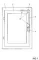
- FIG. 1 shows a window with a pivotable against a frame 1 wings 2 and with a drive rod fitting 3.
- the espagnolette fitting 3 has a longitudinally displaceable, driven by a handle 4 drive rod 5 and has a plurality of interconnected via the drive rod 5 fitting parts 6.
- the fitting parts 6 are exemplified as an edge gear, corner deflection or closure of the espagnolette fitting 3 and one or more holding elements 7, one of which by way of example in FIG. 2 is shown held in a fitting groove 8 of the window.
- FIG. 2 shows a sectional view through one of the fitting parts 6 on one of the holding elements 7 with adjacent areas of the fitting groove 6 of the wing 2 prior to assembly.
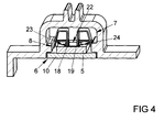
- the holding element 7 has a support 9 with a riveted to the faceplate 10 holding web 11 and radially projecting legs 12, 13.
- the radially projecting legs 12, 13 project beyond the fitting groove in the position shown 8.
- From the holding web 11 are inner legs 14, 15th angled, which are connected via transverse webs 16, 17 with the radially projecting legs 12, 13.
- the transverse webs 16, 17 are arranged parallel to the retaining web 11.
- a centering element 18, 19 projects inwardly toward the inner legs 14, 15.
- the inner legs 14, 15 each have a recess 20, 21 for the centering elements 18, 19.
- the radially projecting legs 12, 13 are compressed during insertion of the fitting part 6 in the fitting groove 8.
- the holding element 7 is made in one piece from spring steel.
- FIG. 3 shows the fitting 6 FIG. 2
- the support 9 of the holding element 7 penetrates a slot 22 of the drive rod 5.
- the drive rod 5 has at its two longitudinal sides in a designated position, here a middle position, each a widening 23, 24 , In these spacers 23, 24 penetrate the two centering elements 18, 19 a. Since the support 9 of the holding element 7 as to FIG. 2 is riveted described with the faceplate 10, the drive rod is the fifth held immovably by the retaining element 7 on the face-plate 10.
- the holding member 7 and the slot 22 of the drive rod 5s are symmetrical.
- the holding element 7 may also have only a single centering element or the broadening of the drive rod 5 may be arranged on only one of the longitudinal sides.
- a holding element at both ends of the fitting parts FIG. 1 arranged.
Landscapes
- Engineering & Computer Science (AREA)
- Mechanical Engineering (AREA)
- Snaps, Bayonet Connections, Set Pins, And Snap Rings (AREA)
- Automatic Assembly (AREA)
- Clamps And Clips (AREA)
Abstract
Description
- Die Erfindung betrifft ein Beschlagteil eines Treibstangenbeschlages eines Fensters oder einer Tür mit einer gegenüber einer feststehenden Stulpschiene verschiebbaren Treibstange, mit einem Halteelement zur Abstützung der Stulpschiene in einer Beschlagnut des Fensters oder der Tür, mit einer zentralen, an der Stulpschiene befestigten, ein Langloch der Treibstange durchdringenden Stütze des Halteelements und mit federnden und radial abstehenden Schenkeln des Halteelements zur Abstützung an Seitenwandungen der Beschlagnut, wobei die radial abstehenden Schenkel in einer außerhalb der Beschlagnut befindlichen Position die Beschlagnut überragen.
- Ein solches Beschlagteil ist beispielsweise aus der
DE 197 30 600 A1 bekannt. Bei diesem Beschlagteil ist die Stütze als Niet ausgebildet und mit einem Ende in der Stulpschiene befestigt. Die sich an der Seitenwand der Beschlagnut abstützenden, radial abstehenden Schenkel sind an dem der Stulpschiene abgewandten Ende der Stütze angeordnet. Weil die radial abstehenden Schenkel in der außerhalb der Beschlagnut befindlichen Position die Beschlagnut überragen, werden die Schenkel bei der Montage des Beschlagteils an dem Fenster zusammengedrückt. Damit stützen die radial abstehenden Schenkel das Beschlagteil in der Beschlagnut ab und erzeugen eine Montagehilfe zur Ausrichtung des Beschlagteils vor einer Verschraubung der Stulpschiene an dem Fenster. - Weiterhin ist aus der
DE 196 46 988 A1 eine Mittenfixierung für ein Beschlagteil bekannt geworden, bei dem an der Stütze des Halteelementes ein Zentrierzapfen angeordnet ist. Dieser Zentrierzapfen dringt in eine entsprechende Aussparung der Treibstange ein und hält diese zunächst unverschiebbar zum Halteelement und damit zur Stulpschiene. Nach dem Einbau des Fensters kann durch erstmaliges Betätigen des Treibstangenbeschlags der Zentrierzapfen an einer vorgesehenen Sollbruchstelle definiert vom Halteelement abgebrochen werden. Diese Gestaltung des Zentrierzapfens führt jedoch zu einer eingeschränkten Materialwahl der Stütze, da der Zentrierzapfen abbrechen muss. Eine gemeinsame Fertigung des Zentrierzapfens und der in einer Beschlagnut abstützenden Schenkel aus Federstahl ist hierdurch nicht möglich. Weiterhin weist ein Treibstangenbeschlag eine Vielzahl von Beschlagteilen, wie Kantengetriebe, Eckumlenkungen und dergleichen auf, welche jeweils mit Mittenfixierungen ausgestattet werden. Dies führt bei der ersten Betätigung des Treibstangenbeschlages zu einem hohen Kraftaufwand. Weiterhin können die abgebrochenen Zentrierzapfen den Betrieb des Treibstangenbeschlages stören. - Der Erfindung liegt das Problem zugrunde, ein Beschlagteil der eingangs genannten Art so zu gestalten, dass es besonders einfach in der vorgesehenen Position montierbar ist und hohe Kräfte sowie abbrechende Bauteile bei der ersten Betätigung des mit dem Beschlagteil ausgestatteten Treibstangenbeschlages vermeidet.
- Dieses Problem wird erfindungsgemäß dadurch gelöst, dass das Langloch in einer Längsseite an einer vorgesehenen Position des Treibstangenbeschlages eine im Verhältnis zu der Länge des Langlochs kurze Verbreiterung aufweist, dass zumindest einer der radial abstehenden Schenkel des Halteelements mit einem Zentrierelement in Verbindung steht und dass das Zentrierelement in der außerhalb der Beschlagnut befindlichen Stellung der radial abstehenden Schenkel in die Verbreiterung eindringt und bei innerhalb der Beschlagnut befindlicher Stellung der radial abstehenden Schenkel außerhalb der Verbreiterung angeordnet ist.
- Durch diese Gestaltung wird die Bewegung des Zentrierelementes bei der Montage des Beschlagteils in der Beschlagnut gesteuert. Außerhalb der Beschlagnut vermag das in die Verbreiterung eindringende Zentrierelement die Treibstange in ihrer vorgesehenen Lage zu der Stulpschiene zu halten und damit die so genannte Mittenfixierung zu erzeugen. Hierdurch lässt sich das erfindungsgemäße Beschlagteil besonders einfach in der vorgesehenen Position, beispielsweise einer Mittelstellung, in der Beschlagnut montieren. Bei der Montage des erfindungsgemäßen Beschlagteils in der Beschlagnut wird das Zentrierelement durch die Bewegung des zumindest einen radial abstehenden Schenkels aus der Verbreiterung heraus bewegt und damit die Bewegung der Treibstange freigegeben. Damit sind bei der ersten Betätigung des mit dem erfindungsgemäßen Beschlagteil ausgestatteten Treibstangenbeschlages keine hohen Kräfte erforderlich. Abbrechende Bauteile oder dergleichen werden ebenfalls vermieden. Die Bewegung des Zentrierelementes ist zudem umkehrbar, wenn das Beschlagteil aus der Beschlagnut demontiert wird. Dabei gelangt das Zentrierelement gegen die Längsseite des Langlochs der Treibstange. Nach einer Verschiebung der Treibstange in die vorgesehene Position rastet das Zentrierelement in der Verbreiterung ein. Die Mittenfixierung ist damit wieder hergestellt. Ein weiterer Vorteil des erfindungsgemäßen Beschlagteils besteht darin, dass sich die Montage des Halteelementes an der Stulpschiene und der Treibstange besonders einfach gestaltet, weil hierbei eine exakte Ausrichtung der Treibstange zu der Stulpschiene nicht erforderlich ist. Das Halteelement lässt sich zunächst in einer beliebigen Stellung der Treibstange zur Stulpschiene durch das Langloch der Treibstange führen und an der Stulpschiene befestigen. Nach der Befestigung des Halteelementes an der Stulpschiene kann die Treibstange verschoben werden, bis das Zentrierelement in der Verbreiterung des Langlochs einrastet. Damit wird die Mittenfixierung der Treibstange zu der Stulpschiene in der vorgesehenen Position erzeugt. Bei dem erfindungsgemäßen Beschlagteil kann es sich beispielsweise um eine so genannte Eckumlenkung, ein Kantengetriebe, einen Verschluss oder dergleichen handeln.
- Das Zentrierelement könnte beispielsweise als an dem zumindest einen Schenkel des Halteelementes befestigter Zapfen ausgebildet sein. Das Halteelement gestaltet sich jedoch gemäß einer anderen vorteilhaften Weiterbildung der Erfindung konstruktiv besonders einfach, wenn das Zentrierelement einstückig mit zumindest einem der radial abstehenden Schenkel gefertigt ist und hakenförmig von diesem Schenkel absteht. Das Zentrierelement und der zumindest eine Schenkel können hierbei einfach aus einem gebogenen und gestanzten Federstahl gefertigt sein.
- Das gesamte Halteelement lässt sich gemäß einer anderen vorteilhaften Weiterbildung der Erfindung einfach im Stanzverfahren fertigen, wenn die radial abstehenden Schenkel jeweils mit einem inneren, das Langloch der Treibstange durchdringenden Schenkel verbunden sind und wenn die inneren Schenkel mit der Stulpschiene verbunden sind. Durch diese Gestaltung bilden die inneren Schenkel einen Teil der das Langloch der Treibstange durchdringenden Stütze. Durch diese Gestaltung weist das Halteelement zudem eine besonders hohe Stabilität und große Federwege auf.
- Das Halteelement weist gemäß einer anderen vorteilhaften Weiterbildung der Erfindung eine große Abstützfläche an der Stulpschiene auf, wenn eine Verbindung der beiden inneren Schenkel einen an der Stulpschiene anliegenden Haltesteg aufweist und wenn die inneren Schenkel von dem Haltesteg abgewinkelt sind. Die an der Stulpschiene befestigte Stütze ist hierdurch konstruktiv besonders einfach aufgebaut. Weiterhin tragen die inneren Schenkel zur Vorspannung der anderen Schenkel gegen die Beschlagnut bei.
- Eine Behinderung der Bewegung des Zentrierelementes durch das Halteelement lässt sich gemäß einer anderen vorteilhaften Weiterbildung der Erfindung einfach vermeiden, wenn zumindest einer der inneren Schenkel eine Ausnehmung für das Zentrierelement aufweist.
- Die Montage des Haleelementes gestaltet sich konstruktiv besonders einfach, wenn das Halteelement im Querschnitt symmetrisch aufgebaut ist und an jedem der radial abstehenden Schenkel jeweils ein Zentrierelement hat. Durch diese Gestaltung ist das Halteelement stets lagerichtig montiert.
- Das Haltelement vermag im von der Beschlagnut demontierten Zustand bei symmetrisch aufgebautem Halteelement hohe Haltekräfte der Treibstange abzustützen, wenn sich die Verbreiterung über beide Längsseiten des Langlochs der Treibstange erstreckt.
- Das Halteelement weist gemäß einer anderen vorteilhaften Weiterbildung der Erfindung eine hohe Stabilität auf, wenn die Verbindung der inneren Schenkel mit den radial abstehenden Schenkeln jeweils einen parallel zum Haltesteg angeordneten Quersteg aufweist.
- Zur Verringerung der Fertigungskosten des Halteelementes trägt es gemäß einer anderen vorteilhaften Weiterbildung der Erfindung bei, wenn das Halteelement einstückig aus Federstahl gefertigt ist.
- Die Erfindung lässt zahlreiche Ausführungsformen zu. Zur weiteren Verdeutlichung ihres Grundprinzips ist eine davon in der Zeichnung dargestellt und wird nachfolgend beschrieben. Diese zeigt in
- Fig. 1
- ein Fenster mit mehreren erfindungsgemäßen Beschlagteilen,
- Fig. 2
- vergrößert eine Schnittdarstellung durch ein Halteelement eines der Beschlagteile aus
Figur 1 mit angrenzenden Bereichen einer Beschlagnut des Fensters und einer Stulpschiene, - Fig. 3
- vergrößert eines der Beschlagteile aus
Figur 1 vor der Montage in einer Beschlagnut, - Fig. 4
- vergrößert das Beschlagteil aus
Figur 3 nach der Montage in der Beschlagnut. -
Figur 1 zeigt ein Fenster mit einem gegen einen Rahmen 1 schwenkbaren Flügel 2 und mit einem Treibstangenbeschlag 3. Der Treibstangenbeschlag 3 weist eine längsverschiebliche, von einer Handhabe 4 antreibbare Treibstange 5 auf und hat mehrere, über die Treibstange 5 miteinander verbundene Beschlagteile 6. Die Beschlagteile 6 sind beispielhaft als Kantengetriebe, Eckumlenkung oder Verschluss des Treibstangenbeschlages 3 ausgebildet und über ein oder mehrere Halteelemente 7, von denen eines beispielhaft inFigur 2 dargestellt ist, in einer Beschlagnut 8 des Fensters gehalten. -
Figur 2 zeigt eine Schnittdarstellung durch eines der Beschlagteile 6 an einem der Halteelemente 7 mit angrenzenden Bereichen der Beschlagnut 6 des Flügels 2 vor der Montage. Zur Vereinfachung der Zeichnung ist die Treibstange 5 inFigur 2 nicht dargestellt. Das Halteelement 7 hat eine Stütze 9 mit einem mit der Stulpschiene 10 vernieteten Haltesteg 11 und radial abstehende Schenkel 12, 13. Die radial abstehenden Schenkel 12, 13 überragen in der dargestellten Stellung die Beschlagnut 8. Von dem Haltesteg 11 sind innere Schenkel 14, 15 abgewinkelt, welche über Querstege 16, 17 mit den radial abstehenden Schenkeln 12, 13 verbunden sind. Die Querstege 16, 17 sind parallel zu dem Haltesteg 11 angeordnet. Von den radial abstehenden Schenkeln 12, 13 ragt jeweils ein Zentrierelement 18, 19 nach innen auf die inneren Schenkel 14, 15 zu. Die inneren Schenkel 14, 15 weisen jeweils eine Ausnehmung 20, 21 für die Zentrierelemente 18, 19 auf. Damit können die radial abstehenden Schenkel 12, 13 beim Einführen des Beschlagteils 6 in die Beschlagnut 8 zusammengedrückt werden. Dabei werden die Zentrierelemente 18, 19 aufeinander zu und gegebenenfalls durch die Ausnehmungen 20, 21 der inneren Schenkel 14, 15 geführt. Das Halteelement 7 ist einstückig aus Federstahl gefertigt. -
Figur 3 zeigt das Beschlagteil 6 ausFigur 2 mit der Treibstange 5 im ungeschnittenen Zustand des Halteelementes 7. Die Stütze 9 des Halteelementes 7 durchdringt ein Langloch 22 der Treibstange 5. Die Treibstange 5 weist an ihren beiden Längsseiten in einer vorgesehenen Position, hier einer mittleren Position, jeweils eine Verbreiterung 23, 24 auf. In diese Verbreiterungen 23, 24 dringen die beiden Zentrierelemente 18, 19 ein. Da die Stütze 9 des Halteelementes 7 wie zuFigur 2 beschrieben mit der Stulpschiene 10 vernietet ist, ist die Treibstange 5 durch das Halteelement 7 unverschiebbar an der Stulpschiene 10 gehalten. - Drückt man das Beschlagteil 6 mit dem Halteelement 7 in die Beschlagnut 8, wie es in
Figur 4 dargestellt ist, werden die radial abstehenden Schenkel 12, 13 zusammengedrückt. Da die Zentrierelemente 18, 19 mit den radial abstehenden Schenkeln 12, 13 verbunden sind, werden diese ebenfalls zusammengedrückt und damit aus den Verbreiterungen 23, 24 des Langlochs 22 der Treibstange 5 herausbewegt. In diesem Zustand lässt sich die Treibstange 5 axial gegenüber der Stulpschiene 10 verschieben. - Das Halteelement 7 und das Langloch 22 der Treibstange 5sind symmetrisch aufgebaut. In alternativen, nicht dargestellten Ausführungsformen kann das Halteelement 7 auch nur ein einziges Zentrierelement aufweisen oder die Verbreiterung der Treibstange 5 an nur einer der Längsseiten angeordnet sein. Vorzugsweise sind jeweils ein Halteelement an beiden Enden der Beschlagteile aus
Figur 1 angeordnet.
Claims (9)
- Beschlagteil eines Treibstangenbeschlages eines Fensters oder einer Tür mit einer gegenüber einer feststehenden Stulpschiene verschiebbaren Treibstange, mit einem Halteelement zur Abstützung der Stulpschiene in einer Beschlagnut des Fensters oder der Tür, mit einer zentralen, an der Stulpschiene befestigten, ein Langloch der Treibstange durchdringenden Stütze des Halteelements und mit federnden und radial abstehenden Schenkeln des Halteelements zur Abstützung an Seitenwandungen der Beschlagnut, wobei die radial abstehenden Schenkel in einer außerhalb der Beschlagnut befindlichen Position die Beschlagnut überragen, dadurch gekennzeichnet, dass das Langloch (22) in einer Längsseite an einer vorgesehenen Position des Treibstangenbeschlages (3) eine im Verhältnis zu der Länge des Langlochs (22) kurze Verbreiterung (23, 24) aufweist, dass zumindest einer der radial abstehenden Schenkel (12, 13) des Halteelements (7) mit einem Zentrierelement (18, 19) in Verbindung steht und dass das Zentrierelement (18, 19) in der außerhalb der Beschlagnut (8) befindlichen Stellung der Schenkel (12, 13) in die Verbreiterung (23, 24) eindringt und bei innerhalb der Beschlagnut (8) befindlicher Stellung der radial abstehenden Schenkel (14, 15) außerhalb der Verbreiterung (23, 24) angeordnet ist.
- Beschlagteil nach Anspruch 1, dadurch gekennzeichnet, dass das Zentrierelement (18, 19) einstückig mit zumindest einem der radial abstehenden Schenkel (12, 13) gefertigt ist und hakenförmig von diesem Schenkel (12, 13) absteht.
- Beschlagteil nach Anspruch 1 oder 2, dadurch gekennzeichnet, dass die radial abstehenden Schenkel (12, 13) jeweils mit einem inneren, das Langloch (22) der Treibstange (5) durchdringenden Schenkel (14, 15) verbunden sind und dass die inneren Schenkel (14, 15) mit der Stulpschiene (10) verbunden sind.
- Beschlagteil nach Anspruch 3, dadurch gekennzeichnet, dass eine Verbindung der beiden inneren Schenkel (14, 15) einen an der Stulpschiene (10) anliegenden Haltesteg (11) aufweist und dass die inneren Schenkel (14, 15) von dem Haltesteg (11) abgewinkelt sind.
- Beschlagteil nach Anspruch 3 oder 4, dadurch gekennzeichnet, dass zumindest einer der inneren Schenkel (14, 15) eine Ausnehmung (20, 21) für das Zentrierelement (18, 19) aufweist.
- Beschlagteil nach einem der vorhergehenden Ansprüche, dadurch gekennzeichnet, dass das Halteelement (7) im Querschnitt symmetrisch aufgebaut ist und an jedem der radial abstehenden Schenkeln (12, 13) jeweils ein Zentrierelement (18, 19) hat.
- Beschlagteil nach einem der vorhergehenden Ansprüche, dadurch gekennzeichnet, dass sich die Verbreiterung (23, 24) über beide Längsseiten des Langlochs (22) der Treibstange (5) erstreckt.
- Beschlagteil nach Anspruch 4, dadurch gekennzeichnet, dass die Verbindung der inneren Schenkel (14, 15) mit den radial abstehenden Schenkeln (12, 13) jeweils einen parallel zum Haltesteg (11) angeordneten Quersteg (16, 17) aufweist.
- Beschlagteil nach einem der vorhergehenden Ansprüche, dadurch gekennzeichnet, dass das Halteelement (7) einstückig aus Federstahl gefertigt ist.
Priority Applications (1)
| Application Number | Priority Date | Filing Date | Title |
|---|---|---|---|
| PL09164855T PL2151537T3 (pl) | 2008-08-07 | 2009-07-08 | Część okucia z drążkiem napędowym |
Applications Claiming Priority (1)
| Application Number | Priority Date | Filing Date | Title |
|---|---|---|---|
| DE102008041083A DE102008041083A1 (de) | 2008-08-07 | 2008-08-07 | Beschlagteil eines Treibstangenbeschlages |
Publications (3)
| Publication Number | Publication Date |
|---|---|
| EP2151537A2 true EP2151537A2 (de) | 2010-02-10 |
| EP2151537A3 EP2151537A3 (de) | 2011-07-27 |
| EP2151537B1 EP2151537B1 (de) | 2014-05-07 |
Family
ID=41050375
Family Applications (1)
| Application Number | Title | Priority Date | Filing Date |
|---|---|---|---|
| EP09164855.0A Active EP2151537B1 (de) | 2008-08-07 | 2009-07-08 | Beschlagteil eines Treibstangenbeschlages |
Country Status (4)
| Country | Link |
|---|---|
| EP (1) | EP2151537B1 (de) |
| DE (1) | DE102008041083A1 (de) |
| ES (1) | ES2471144T3 (de) |
| PL (1) | PL2151537T3 (de) |
Cited By (3)
| Publication number | Priority date | Publication date | Assignee | Title |
|---|---|---|---|---|
| EP2581532A3 (de) * | 2011-10-13 | 2017-07-19 | Aug. Winkhaus GmbH & Co. KG | Eckumlenkung für einen Treibstangenbeschlag eines Fensters |
| EP2607583A3 (de) * | 2011-12-20 | 2017-11-15 | Aug. Winkhaus GmbH & Co. KG | Beschlagteil für einen Treibstangenbeschlag |
| DE102019200158A1 (de) | 2019-01-09 | 2020-07-09 | Aug. Winkhaus Gmbh & Co. Kg | Halteelement eines beschlagteils eines treibstangenbeschlages |
Families Citing this family (1)
| Publication number | Priority date | Publication date | Assignee | Title |
|---|---|---|---|---|
| DE202010004012U1 (de) | 2010-03-22 | 2010-06-17 | Roto Frank Ag | Befestigungselement für Stulpschienenbeschläge für Fenster und Türen |
Citations (2)
| Publication number | Priority date | Publication date | Assignee | Title |
|---|---|---|---|---|
| DE19646988A1 (de) | 1996-11-14 | 1998-05-20 | Roto Frank Ag | Beschlag für ein Fenster |
| DE19730600A1 (de) | 1997-07-17 | 1999-01-21 | Siegenia Frank Kg | Stulpschienenbeschlag |
Family Cites Families (7)
| Publication number | Priority date | Publication date | Assignee | Title |
|---|---|---|---|---|
| DE2658465C3 (de) * | 1976-12-23 | 1982-06-16 | Siegenia-Frank Kg, 5900 Siegen | Vorrichtung zum Befestigen der Stulpschienen von Treibstangenbeschlägen für Fenster und Türen aus Holz oder Kunststoff |
| DE29514640U1 (de) * | 1995-09-12 | 1995-11-23 | Aug. Winkhaus GmbH & Co. KG, 48291 Telgte | Treibstangenbeschlag für Türen, Fenster o.dgl. |
| DE19709283C2 (de) * | 1997-03-07 | 1999-02-25 | Siegenia Frank Kg | Kantengetriebe |
| DE19820742A1 (de) * | 1998-05-08 | 1999-11-11 | Winkhaus Fa August | Beschlagteil eines an einem Rahmen anzubringenden Beschlagsystems, beispielsweise eines Fenster- oder Türbeschlags |
| DE19934842A1 (de) * | 1999-07-24 | 2001-02-01 | Wicona Bausysteme Gmbh | Beschlag für die Verriegelung von Fenstern oder Türen |
| DE19948862A1 (de) * | 1999-10-08 | 2001-04-12 | Schueco Int Kg | Schließeinrichtung für einen Beschlag zur Verriegelung eines beweglichen Rahmenteils eines Fensters oder einer Tür |
| DE20105984U1 (de) * | 2001-03-26 | 2001-07-05 | Gretsch-Unitas GmbH Baubeschläge, 71254 Ditzingen | Stulpschiene für einen Treibstangenbeschlag für Fenster, Türen o.dgl. sowie Treibstangenbeschlag mit einer solchen Stulpschiene |
-
2008
- 2008-08-07 DE DE102008041083A patent/DE102008041083A1/de not_active Withdrawn
-
2009
- 2009-07-08 EP EP09164855.0A patent/EP2151537B1/de active Active
- 2009-07-08 ES ES09164855.0T patent/ES2471144T3/es active Active
- 2009-07-08 PL PL09164855T patent/PL2151537T3/pl unknown
Patent Citations (2)
| Publication number | Priority date | Publication date | Assignee | Title |
|---|---|---|---|---|
| DE19646988A1 (de) | 1996-11-14 | 1998-05-20 | Roto Frank Ag | Beschlag für ein Fenster |
| DE19730600A1 (de) | 1997-07-17 | 1999-01-21 | Siegenia Frank Kg | Stulpschienenbeschlag |
Cited By (4)
| Publication number | Priority date | Publication date | Assignee | Title |
|---|---|---|---|---|
| EP2581532A3 (de) * | 2011-10-13 | 2017-07-19 | Aug. Winkhaus GmbH & Co. KG | Eckumlenkung für einen Treibstangenbeschlag eines Fensters |
| EP2607583A3 (de) * | 2011-12-20 | 2017-11-15 | Aug. Winkhaus GmbH & Co. KG | Beschlagteil für einen Treibstangenbeschlag |
| DE102019200158A1 (de) | 2019-01-09 | 2020-07-09 | Aug. Winkhaus Gmbh & Co. Kg | Halteelement eines beschlagteils eines treibstangenbeschlages |
| EP3683387A1 (de) | 2019-01-09 | 2020-07-22 | Aug. Winkhaus GmbH & Co. KG | Halteelement eines beschlagteils eines treibstangenbeschlages |
Also Published As
| Publication number | Publication date |
|---|---|
| PL2151537T3 (pl) | 2014-08-29 |
| EP2151537B1 (de) | 2014-05-07 |
| EP2151537A3 (de) | 2011-07-27 |
| ES2471144T3 (es) | 2014-06-25 |
| DE102008041083A1 (de) | 2010-02-11 |
Similar Documents
| Publication | Publication Date | Title |
|---|---|---|
| DE102009024983A1 (de) | Verbindungsbaugruppe | |
| EP0843062A2 (de) | Halteelement für Fensterbeschlag | |
| EP2498643B1 (de) | Vorrichtung zur koppelung eines schubkastens mit einer laufschiene einer auszugsführung | |
| EP2151537B1 (de) | Beschlagteil eines Treibstangenbeschlages | |
| EP1984590A1 (de) | Verspannbare befestigungseinrichtung | |
| EP2228503A1 (de) | Paneele | |
| EP2592965B1 (de) | Schubkasten mit zwei seitenzargen und einer rückwand | |
| DE10361445B4 (de) | Kraftfahrzeugtürschloss | |
| EP2754805B1 (de) | Riegelstange für einen Riegelstangenbeschlag | |
| EP2246508A2 (de) | Treibstangenschloss mit Falle und Schubriegel | |
| EP2252751B1 (de) | Treibstangenbeschlag für fenster oder tür | |
| DE19646982A1 (de) | Beschlag für ein Fenster | |
| EP3173556B1 (de) | Montageelement zur befestigung von türbändern | |
| AT508129A4 (de) | Befestigungsvorrichtung für einen möbelbeschlag | |
| EP1863990B1 (de) | Treibstangenantrieb | |
| EP1577465B1 (de) | Schlosselement mit Befestigung für Betätigungselement | |
| EP3235984B1 (de) | Beschlag für ein fenster, verfahren zum herstellen des beschlags sowie entsprechendes fenster | |
| EP1724417A2 (de) | Schlosselement | |
| EP1580371B1 (de) | Beschlaganordnung | |
| EP2155998B1 (de) | Treibstangenanordnung sowie verfahren zur montage einer treibstangenanordnung | |
| DE102013000256A1 (de) | Befestigung fûr einen Drücker | |
| DE102012100654A1 (de) | Gleitstück, Gleitschiene und damit versehene Gleitschienenanordnung für Gleitschienengestänge sowie Türbetätiger | |
| EP1884612B1 (de) | Beschlagteil für einen Treibstangenbeschlag | |
| EP2543803B1 (de) | Treibstange für einen Treibstangenbeschlag | |
| DE202022105395U1 (de) | Verriegelungsvorrichtung und Türanordnung mit einer solchen Verriegelungsvorrichtung |
Legal Events
| Date | Code | Title | Description |
|---|---|---|---|
| PUAI | Public reference made under article 153(3) epc to a published international application that has entered the european phase |
Free format text: ORIGINAL CODE: 0009012 |
|
| AK | Designated contracting states |
Kind code of ref document: A2 Designated state(s): AT BE BG CH CY CZ DE DK EE ES FI FR GB GR HR HU IE IS IT LI LT LU LV MC MK MT NL NO PL PT RO SE SI SK SM TR |
|
| AX | Request for extension of the european patent |
Extension state: AL BA RS |
|
| PUAL | Search report despatched |
Free format text: ORIGINAL CODE: 0009013 |
|
| AK | Designated contracting states |
Kind code of ref document: A3 Designated state(s): AT BE BG CH CY CZ DE DK EE ES FI FR GB GR HR HU IE IS IT LI LT LU LV MC MK MT NL NO PL PT RO SE SI SK SM TR |
|
| AX | Request for extension of the european patent |
Extension state: AL BA RS |
|
| 17P | Request for examination filed |
Effective date: 20111208 |
|
| GRAP | Despatch of communication of intention to grant a patent |
Free format text: ORIGINAL CODE: EPIDOSNIGR1 |
|
| INTG | Intention to grant announced |
Effective date: 20140116 |
|
| GRAS | Grant fee paid |
Free format text: ORIGINAL CODE: EPIDOSNIGR3 |
|
| GRAA | (expected) grant |
Free format text: ORIGINAL CODE: 0009210 |
|
| AK | Designated contracting states |
Kind code of ref document: B1 Designated state(s): AT BE BG CH CY CZ DE DK EE ES FI FR GB GR HR HU IE IS IT LI LT LU LV MC MK MT NL NO PL PT RO SE SI SK SM TR |
|
| REG | Reference to a national code |
Ref country code: GB Ref legal event code: FG4D Free format text: NOT ENGLISH |
|
| REG | Reference to a national code |
Ref country code: AT Ref legal event code: REF Ref document number: 666856 Country of ref document: AT Kind code of ref document: T Effective date: 20140515 |
|
| REG | Reference to a national code |
Ref country code: IE Ref legal event code: FG4D Free format text: LANGUAGE OF EP DOCUMENT: GERMAN |
|
| REG | Reference to a national code |
Ref country code: DE Ref legal event code: R096 Ref document number: 502009009340 Country of ref document: DE Effective date: 20140618 |
|
| REG | Reference to a national code |
Ref country code: ES Ref legal event code: FG2A Ref document number: 2471144 Country of ref document: ES Kind code of ref document: T3 Effective date: 20140625 |
|
| REG | Reference to a national code |
Ref country code: RO Ref legal event code: EPE |
|
| REG | Reference to a national code |
Ref country code: PL Ref legal event code: T3 |
|
| REG | Reference to a national code |
Ref country code: NL Ref legal event code: VDEP Effective date: 20140507 |
|
| REG | Reference to a national code |
Ref country code: LT Ref legal event code: MG4D |
|
| PG25 | Lapsed in a contracting state [announced via postgrant information from national office to epo] |
Ref country code: NO Free format text: LAPSE BECAUSE OF FAILURE TO SUBMIT A TRANSLATION OF THE DESCRIPTION OR TO PAY THE FEE WITHIN THE PRESCRIBED TIME-LIMIT Effective date: 20140807 Ref country code: GR Free format text: LAPSE BECAUSE OF FAILURE TO SUBMIT A TRANSLATION OF THE DESCRIPTION OR TO PAY THE FEE WITHIN THE PRESCRIBED TIME-LIMIT Effective date: 20140808 Ref country code: CY Free format text: LAPSE BECAUSE OF FAILURE TO SUBMIT A TRANSLATION OF THE DESCRIPTION OR TO PAY THE FEE WITHIN THE PRESCRIBED TIME-LIMIT Effective date: 20140507 Ref country code: FI Free format text: LAPSE BECAUSE OF FAILURE TO SUBMIT A TRANSLATION OF THE DESCRIPTION OR TO PAY THE FEE WITHIN THE PRESCRIBED TIME-LIMIT Effective date: 20140507 Ref country code: LT Free format text: LAPSE BECAUSE OF FAILURE TO SUBMIT A TRANSLATION OF THE DESCRIPTION OR TO PAY THE FEE WITHIN THE PRESCRIBED TIME-LIMIT Effective date: 20140507 Ref country code: IS Free format text: LAPSE BECAUSE OF FAILURE TO SUBMIT A TRANSLATION OF THE DESCRIPTION OR TO PAY THE FEE WITHIN THE PRESCRIBED TIME-LIMIT Effective date: 20140907 |
|
| PG25 | Lapsed in a contracting state [announced via postgrant information from national office to epo] |
Ref country code: SE Free format text: LAPSE BECAUSE OF FAILURE TO SUBMIT A TRANSLATION OF THE DESCRIPTION OR TO PAY THE FEE WITHIN THE PRESCRIBED TIME-LIMIT Effective date: 20140507 Ref country code: HR Free format text: LAPSE BECAUSE OF FAILURE TO SUBMIT A TRANSLATION OF THE DESCRIPTION OR TO PAY THE FEE WITHIN THE PRESCRIBED TIME-LIMIT Effective date: 20140507 Ref country code: LV Free format text: LAPSE BECAUSE OF FAILURE TO SUBMIT A TRANSLATION OF THE DESCRIPTION OR TO PAY THE FEE WITHIN THE PRESCRIBED TIME-LIMIT Effective date: 20140507 |
|
| PG25 | Lapsed in a contracting state [announced via postgrant information from national office to epo] |
Ref country code: PT Free format text: LAPSE BECAUSE OF FAILURE TO SUBMIT A TRANSLATION OF THE DESCRIPTION OR TO PAY THE FEE WITHIN THE PRESCRIBED TIME-LIMIT Effective date: 20140908 |
|
| PG25 | Lapsed in a contracting state [announced via postgrant information from national office to epo] |
Ref country code: DK Free format text: LAPSE BECAUSE OF FAILURE TO SUBMIT A TRANSLATION OF THE DESCRIPTION OR TO PAY THE FEE WITHIN THE PRESCRIBED TIME-LIMIT Effective date: 20140507 Ref country code: EE Free format text: LAPSE BECAUSE OF FAILURE TO SUBMIT A TRANSLATION OF THE DESCRIPTION OR TO PAY THE FEE WITHIN THE PRESCRIBED TIME-LIMIT Effective date: 20140507 Ref country code: SK Free format text: LAPSE BECAUSE OF FAILURE TO SUBMIT A TRANSLATION OF THE DESCRIPTION OR TO PAY THE FEE WITHIN THE PRESCRIBED TIME-LIMIT Effective date: 20140507 Ref country code: CZ Free format text: LAPSE BECAUSE OF FAILURE TO SUBMIT A TRANSLATION OF THE DESCRIPTION OR TO PAY THE FEE WITHIN THE PRESCRIBED TIME-LIMIT Effective date: 20140507 |
|
| REG | Reference to a national code |
Ref country code: DE Ref legal event code: R097 Ref document number: 502009009340 Country of ref document: DE |
|
| PG25 | Lapsed in a contracting state [announced via postgrant information from national office to epo] |
Ref country code: NL Free format text: LAPSE BECAUSE OF FAILURE TO SUBMIT A TRANSLATION OF THE DESCRIPTION OR TO PAY THE FEE WITHIN THE PRESCRIBED TIME-LIMIT Effective date: 20140507 Ref country code: LU Free format text: LAPSE BECAUSE OF FAILURE TO SUBMIT A TRANSLATION OF THE DESCRIPTION OR TO PAY THE FEE WITHIN THE PRESCRIBED TIME-LIMIT Effective date: 20140708 |
|
| REG | Reference to a national code |
Ref country code: CH Ref legal event code: PL |
|
| PLBE | No opposition filed within time limit |
Free format text: ORIGINAL CODE: 0009261 |
|
| STAA | Information on the status of an ep patent application or granted ep patent |
Free format text: STATUS: NO OPPOSITION FILED WITHIN TIME LIMIT |
|
| 26N | No opposition filed |
Effective date: 20150210 |
|
| PG25 | Lapsed in a contracting state [announced via postgrant information from national office to epo] |
Ref country code: LI Free format text: LAPSE BECAUSE OF NON-PAYMENT OF DUE FEES Effective date: 20140731 Ref country code: CH Free format text: LAPSE BECAUSE OF NON-PAYMENT OF DUE FEES Effective date: 20140731 |
|
| REG | Reference to a national code |
Ref country code: DE Ref legal event code: R097 Ref document number: 502009009340 Country of ref document: DE Effective date: 20150210 |
|
| PG25 | Lapsed in a contracting state [announced via postgrant information from national office to epo] |
Ref country code: SI Free format text: LAPSE BECAUSE OF FAILURE TO SUBMIT A TRANSLATION OF THE DESCRIPTION OR TO PAY THE FEE WITHIN THE PRESCRIBED TIME-LIMIT Effective date: 20140507 |
|
| PG25 | Lapsed in a contracting state [announced via postgrant information from national office to epo] |
Ref country code: MC Free format text: LAPSE BECAUSE OF FAILURE TO SUBMIT A TRANSLATION OF THE DESCRIPTION OR TO PAY THE FEE WITHIN THE PRESCRIBED TIME-LIMIT Effective date: 20140507 Ref country code: SM Free format text: LAPSE BECAUSE OF FAILURE TO SUBMIT A TRANSLATION OF THE DESCRIPTION OR TO PAY THE FEE WITHIN THE PRESCRIBED TIME-LIMIT Effective date: 20140507 |
|
| PG25 | Lapsed in a contracting state [announced via postgrant information from national office to epo] |
Ref country code: MT Free format text: LAPSE BECAUSE OF FAILURE TO SUBMIT A TRANSLATION OF THE DESCRIPTION OR TO PAY THE FEE WITHIN THE PRESCRIBED TIME-LIMIT Effective date: 20140507 Ref country code: BG Free format text: LAPSE BECAUSE OF FAILURE TO SUBMIT A TRANSLATION OF THE DESCRIPTION OR TO PAY THE FEE WITHIN THE PRESCRIBED TIME-LIMIT Effective date: 20140507 |
|
| REG | Reference to a national code |
Ref country code: FR Ref legal event code: PLFP Year of fee payment: 8 |
|
| PG25 | Lapsed in a contracting state [announced via postgrant information from national office to epo] |
Ref country code: HU Free format text: LAPSE BECAUSE OF FAILURE TO SUBMIT A TRANSLATION OF THE DESCRIPTION OR TO PAY THE FEE WITHIN THE PRESCRIBED TIME-LIMIT; INVALID AB INITIO Effective date: 20090708 |
|
| REG | Reference to a national code |
Ref country code: FR Ref legal event code: PLFP Year of fee payment: 9 |
|
| PGFP | Annual fee paid to national office [announced via postgrant information from national office to epo] |
Ref country code: GR Payment date: 20170919 Year of fee payment: 9 |
|
| PGFP | Annual fee paid to national office [announced via postgrant information from national office to epo] |
Ref country code: PL Payment date: 20170706 Year of fee payment: 9 Ref country code: IE Payment date: 20170726 Year of fee payment: 9 |
|
| PG25 | Lapsed in a contracting state [announced via postgrant information from national office to epo] |
Ref country code: MK Free format text: LAPSE BECAUSE OF FAILURE TO SUBMIT A TRANSLATION OF THE DESCRIPTION OR TO PAY THE FEE WITHIN THE PRESCRIBED TIME-LIMIT Effective date: 20140507 |
|
| REG | Reference to a national code |
Ref country code: FR Ref legal event code: PLFP Year of fee payment: 10 |
|
| REG | Reference to a national code |
Ref country code: IE Ref legal event code: MM4A |
|
| PG25 | Lapsed in a contracting state [announced via postgrant information from national office to epo] |
Ref country code: IE Free format text: LAPSE BECAUSE OF NON-PAYMENT OF DUE FEES Effective date: 20180708 Ref country code: RO Free format text: LAPSE BECAUSE OF NON-PAYMENT OF DUE FEES Effective date: 20180708 |
|
| PGFP | Annual fee paid to national office [announced via postgrant information from national office to epo] |
Ref country code: ES Payment date: 20190826 Year of fee payment: 11 |
|
| PGFP | Annual fee paid to national office [announced via postgrant information from national office to epo] |
Ref country code: AT Payment date: 20190722 Year of fee payment: 11 |
|
| GBPC | Gb: european patent ceased through non-payment of renewal fee |
Effective date: 20190708 |
|
| PG25 | Lapsed in a contracting state [announced via postgrant information from national office to epo] |
Ref country code: GB Free format text: LAPSE BECAUSE OF NON-PAYMENT OF DUE FEES Effective date: 20190708 Ref country code: PL Free format text: LAPSE BECAUSE OF NON-PAYMENT OF DUE FEES Effective date: 20180708 |
|
| PGFP | Annual fee paid to national office [announced via postgrant information from national office to epo] |
Ref country code: TR Payment date: 20200624 Year of fee payment: 12 |
|
| PG25 | Lapsed in a contracting state [announced via postgrant information from national office to epo] |
Ref country code: IT Free format text: LAPSE BECAUSE OF NON-PAYMENT OF DUE FEES Effective date: 20190708 |
|
| PGFP | Annual fee paid to national office [announced via postgrant information from national office to epo] |
Ref country code: BE Payment date: 20200727 Year of fee payment: 12 |
|
| REG | Reference to a national code |
Ref country code: AT Ref legal event code: MM01 Ref document number: 666856 Country of ref document: AT Kind code of ref document: T Effective date: 20200708 |
|
| PG25 | Lapsed in a contracting state [announced via postgrant information from national office to epo] |
Ref country code: AT Free format text: LAPSE BECAUSE OF NON-PAYMENT OF DUE FEES Effective date: 20200708 |
|
| PGFP | Annual fee paid to national office [announced via postgrant information from national office to epo] |
Ref country code: FR Payment date: 20210726 Year of fee payment: 13 |
|
| REG | Reference to a national code |
Ref country code: ES Ref legal event code: FD2A Effective date: 20211229 |
|
| PG25 | Lapsed in a contracting state [announced via postgrant information from national office to epo] |
Ref country code: ES Free format text: LAPSE BECAUSE OF NON-PAYMENT OF DUE FEES Effective date: 20200709 |
|
| REG | Reference to a national code |
Ref country code: BE Ref legal event code: MM Effective date: 20210731 |
|
| PG25 | Lapsed in a contracting state [announced via postgrant information from national office to epo] |
Ref country code: TR Free format text: LAPSE BECAUSE OF NON-PAYMENT OF DUE FEES Effective date: 20210708 |
|
| PG25 | Lapsed in a contracting state [announced via postgrant information from national office to epo] |
Ref country code: BE Free format text: LAPSE BECAUSE OF NON-PAYMENT OF DUE FEES Effective date: 20210731 |
|
| PG25 | Lapsed in a contracting state [announced via postgrant information from national office to epo] |
Ref country code: FR Free format text: LAPSE BECAUSE OF NON-PAYMENT OF DUE FEES Effective date: 20220731 |
|
| P01 | Opt-out of the competence of the unified patent court (upc) registered |
Effective date: 20230515 |
|
| REG | Reference to a national code |
Ref country code: DE Ref legal event code: R081 Ref document number: 502009009340 Country of ref document: DE Owner name: AUG. WINKHAUS SE & CO. KG, DE Free format text: FORMER OWNER: AUG. WINKHAUS GMBH & CO. KG, 48291 TELGTE, DE Ref country code: DE Ref legal event code: R081 Ref document number: 502009009340 Country of ref document: DE Owner name: AUG. WINKHAUS SE, DE Free format text: FORMER OWNER: AUG. WINKHAUS GMBH & CO. KG, 48291 TELGTE, DE |
|
| REG | Reference to a national code |
Ref country code: DE Ref legal event code: R081 Ref document number: 502009009340 Country of ref document: DE Owner name: AUG. WINKHAUS SE, DE Free format text: FORMER OWNER: AUG. WINKHAUS SE & CO. KG, 48291 TELGTE, DE |
|
| PGFP | Annual fee paid to national office [announced via postgrant information from national office to epo] |
Ref country code: DE Payment date: 20250722 Year of fee payment: 17 |