EP2150092A2 - Vorrichtung zur Erwärmung von Formteilen, insbesondere dentalkeramischen Formteilen - Google Patents
Vorrichtung zur Erwärmung von Formteilen, insbesondere dentalkeramischen Formteilen Download PDFInfo
- Publication number
- EP2150092A2 EP2150092A2 EP09164746A EP09164746A EP2150092A2 EP 2150092 A2 EP2150092 A2 EP 2150092A2 EP 09164746 A EP09164746 A EP 09164746A EP 09164746 A EP09164746 A EP 09164746A EP 2150092 A2 EP2150092 A2 EP 2150092A2
- Authority
- EP
- European Patent Office
- Prior art keywords
- susceptor
- outer ring
- inner ring
- microwave
- microwave radiation
- Prior art date
- Legal status (The legal status is an assumption and is not a legal conclusion. Google has not performed a legal analysis and makes no representation as to the accuracy of the status listed.)
- Granted
Links
- 238000010438 heat treatment Methods 0.000 title claims description 19
- 239000000919 ceramic Substances 0.000 title 1
- 230000005855 radiation Effects 0.000 claims abstract description 41
- 238000000465 moulding Methods 0.000 claims abstract description 29
- VYPSYNLAJGMNEJ-UHFFFAOYSA-N Silicium dioxide Chemical compound O=[Si]=O VYPSYNLAJGMNEJ-UHFFFAOYSA-N 0.000 claims abstract description 8
- MCMNRKCIXSYSNV-UHFFFAOYSA-N ZrO2 Inorganic materials O=[Zr]=O MCMNRKCIXSYSNV-UHFFFAOYSA-N 0.000 claims abstract description 8
- 239000004065 semiconductor Substances 0.000 claims abstract description 8
- 235000012239 silicon dioxide Nutrition 0.000 claims abstract description 4
- 239000000377 silicon dioxide Substances 0.000 claims abstract description 4
- 239000011241 protective layer Substances 0.000 claims abstract description 3
- 239000011351 dental ceramic Substances 0.000 claims description 7
- 125000006850 spacer group Chemical group 0.000 claims description 3
- 239000000843 powder Substances 0.000 claims description 2
- 229910018072 Al 2 O 3 Inorganic materials 0.000 claims 1
- RVTZCBVAJQQJTK-UHFFFAOYSA-N oxygen(2-);zirconium(4+) Chemical compound [O-2].[O-2].[Zr+4] RVTZCBVAJQQJTK-UHFFFAOYSA-N 0.000 abstract description 2
- TWNQGVIAIRXVLR-UHFFFAOYSA-N oxo(oxoalumanyloxy)alumane Chemical compound O=[Al]O[Al]=O TWNQGVIAIRXVLR-UHFFFAOYSA-N 0.000 abstract 1
- 239000000463 material Substances 0.000 description 7
- HBMJWWWQQXIZIP-UHFFFAOYSA-N silicon carbide Chemical compound [Si+]#[C-] HBMJWWWQQXIZIP-UHFFFAOYSA-N 0.000 description 7
- 229910010271 silicon carbide Inorganic materials 0.000 description 7
- 230000002349 favourable effect Effects 0.000 description 5
- 229910052581 Si3N4 Inorganic materials 0.000 description 3
- PNEYBMLMFCGWSK-UHFFFAOYSA-N aluminium oxide Inorganic materials [O-2].[O-2].[O-2].[Al+3].[Al+3] PNEYBMLMFCGWSK-UHFFFAOYSA-N 0.000 description 3
- 229910052593 corundum Inorganic materials 0.000 description 3
- 238000010304 firing Methods 0.000 description 3
- 229910001845 yogo sapphire Inorganic materials 0.000 description 3
- 230000000694 effects Effects 0.000 description 2
- 238000000265 homogenisation Methods 0.000 description 2
- INZDTEICWPZYJM-UHFFFAOYSA-N 1-(chloromethyl)-4-[4-(chloromethyl)phenyl]benzene Chemical compound C1=CC(CCl)=CC=C1C1=CC=C(CCl)C=C1 INZDTEICWPZYJM-UHFFFAOYSA-N 0.000 description 1
- QIJNJJZPYXGIQM-UHFFFAOYSA-N 1lambda4,2lambda4-dimolybdacyclopropa-1,2,3-triene Chemical compound [Mo]=C=[Mo] QIJNJJZPYXGIQM-UHFFFAOYSA-N 0.000 description 1
- OYPRJOBELJOOCE-UHFFFAOYSA-N Calcium Chemical compound [Ca] OYPRJOBELJOOCE-UHFFFAOYSA-N 0.000 description 1
- 229910039444 MoC Inorganic materials 0.000 description 1
- XUIMIQQOPSSXEZ-UHFFFAOYSA-N Silicon Chemical compound [Si] XUIMIQQOPSSXEZ-UHFFFAOYSA-N 0.000 description 1
- QCWXUUIWCKQGHC-UHFFFAOYSA-N Zirconium Chemical compound [Zr] QCWXUUIWCKQGHC-UHFFFAOYSA-N 0.000 description 1
- -1 Zirkoniumnitird Chemical compound 0.000 description 1
- 229910026551 ZrC Inorganic materials 0.000 description 1
- LRTTZMZPZHBOPO-UHFFFAOYSA-N [B].[B].[Hf] Chemical compound [B].[B].[Hf] LRTTZMZPZHBOPO-UHFFFAOYSA-N 0.000 description 1
- OTCHGXYCWNXDOA-UHFFFAOYSA-N [C].[Zr] Chemical compound [C].[Zr] OTCHGXYCWNXDOA-UHFFFAOYSA-N 0.000 description 1
- 238000010521 absorption reaction Methods 0.000 description 1
- 229910002113 barium titanate Inorganic materials 0.000 description 1
- 229910052791 calcium Inorganic materials 0.000 description 1
- 239000011575 calcium Substances 0.000 description 1
- 230000002301 combined effect Effects 0.000 description 1
- 238000001816 cooling Methods 0.000 description 1
- 230000008878 coupling Effects 0.000 description 1
- 238000010168 coupling process Methods 0.000 description 1
- 238000005859 coupling reaction Methods 0.000 description 1
- 239000013078 crystal Substances 0.000 description 1
- 238000011161 development Methods 0.000 description 1
- 230000018109 developmental process Effects 0.000 description 1
- 238000002474 experimental method Methods 0.000 description 1
- 239000007789 gas Substances 0.000 description 1
- WHJFNYXPKGDKBB-UHFFFAOYSA-N hafnium;methane Chemical compound C.[Hf] WHJFNYXPKGDKBB-UHFFFAOYSA-N 0.000 description 1
- 230000006698 induction Effects 0.000 description 1
- 238000009413 insulation Methods 0.000 description 1
- 239000012774 insulation material Substances 0.000 description 1
- UNASZPQZIFZUSI-UHFFFAOYSA-N methylidyneniobium Chemical compound [Nb]#C UNASZPQZIFZUSI-UHFFFAOYSA-N 0.000 description 1
- NFFIWVVINABMKP-UHFFFAOYSA-N methylidynetantalum Chemical compound [Ta]#C NFFIWVVINABMKP-UHFFFAOYSA-N 0.000 description 1
- 239000000203 mixture Substances 0.000 description 1
- 229910052710 silicon Inorganic materials 0.000 description 1
- 239000010703 silicon Substances 0.000 description 1
- HQVNEWCFYHHQES-UHFFFAOYSA-N silicon nitride Chemical compound N12[Si]34N5[Si]62N3[Si]51N64 HQVNEWCFYHHQES-UHFFFAOYSA-N 0.000 description 1
- 238000005245 sintering Methods 0.000 description 1
- 229910003468 tantalcarbide Inorganic materials 0.000 description 1
- 238000007669 thermal treatment Methods 0.000 description 1
- MTPVUVINMAGMJL-UHFFFAOYSA-N trimethyl(1,1,2,2,2-pentafluoroethyl)silane Chemical compound C[Si](C)(C)C(F)(F)C(F)(F)F MTPVUVINMAGMJL-UHFFFAOYSA-N 0.000 description 1
- 229910052726 zirconium Inorganic materials 0.000 description 1
Images

Classifications
-
- H—ELECTRICITY
- H05—ELECTRIC TECHNIQUES NOT OTHERWISE PROVIDED FOR
- H05B—ELECTRIC HEATING; ELECTRIC LIGHT SOURCES NOT OTHERWISE PROVIDED FOR; CIRCUIT ARRANGEMENTS FOR ELECTRIC LIGHT SOURCES, IN GENERAL
- H05B6/00—Heating by electric, magnetic or electromagnetic fields
- H05B6/64—Heating using microwaves
- H05B6/80—Apparatus for specific applications
-
- A—HUMAN NECESSITIES
- A61—MEDICAL OR VETERINARY SCIENCE; HYGIENE
- A61C—DENTISTRY; APPARATUS OR METHODS FOR ORAL OR DENTAL HYGIENE
- A61C13/00—Dental prostheses; Making same
- A61C13/20—Methods or devices for soldering, casting, moulding or melting
- A61C13/203—Methods or devices for soldering, casting, moulding or melting using microwave energy
-
- H—ELECTRICITY
- H05—ELECTRIC TECHNIQUES NOT OTHERWISE PROVIDED FOR
- H05B—ELECTRIC HEATING; ELECTRIC LIGHT SOURCES NOT OTHERWISE PROVIDED FOR; CIRCUIT ARRANGEMENTS FOR ELECTRIC LIGHT SOURCES, IN GENERAL
- H05B2206/00—Aspects relating to heating by electric, magnetic, or electromagnetic fields covered by group H05B6/00
- H05B2206/04—Heating using microwaves
- H05B2206/046—Microwave drying of wood, ink, food, ceramic, sintering of ceramic, clothes, hair
Definitions
- the invention relates to a device for heating molded parts, in particular dental ceramic molded parts, in a microwave oven, according to the preamble of claim 1.
- Such a furnace is for example from the EP 1 060 713 A1 known.
- dental ceramics are exposed to microwave radiation, whereby susceptors can be used which receive the microwave radiation and thereby heat up, whereby the dental molding is also heated.
- dental ceramics imparted to a conventional infrared heater typically sinter from the outside to the inside after the heat given off by heat radiation or convection is supplied to the dental molding from the outside
- microwaves have the advantage that they are also basically suitable for molding a dental molding from the inside heat.
- the invention has for its object to provide a device for heating moldings, in particular dental ceramic moldings, according to the preamble of claim 1, which allows an improved restoration result, without an extension of the cycle time would be required, preferably the cycle time can be shortened.
- an inner ring and an outer ring of susceptors around the molded part, wherein the molded part is received in the annular space thus formed.
- this measure results in a more uniform heating, which is due to the fact that a large proportion of the microwave radiation penetrates into the annulus through the large-area, but comparatively thin-walled susceptors, and thus an equilibrium is generated from the heat radiation and microwave radiation emitted by the susceptors.
- This balance leads to the uniform heating of the molding both from the inside and from the outside, so that the temperature gradient is greatly reduced with proper design of inner ring and outer ring, even when working with a comparatively high performance and thus a rapid heating.
- both inner ring and outer ring are formed as upstanding rings, between which the annular space extends, wherein neither of the two rings must be completely closed. In this case, neither in the inner ring nor in the outer ring flow appreciable currents, and both rings act as passive susceptors.
- the rings closed and build from a temperature-resistant semiconductor which is also susceptor for microwave radiation.
- a temperature-resistant semiconductor which is also susceptor for microwave radiation.
- microwave radiation induced and the induced currents are power consuming and thus put microwave radiation in addition to heat.
- the semiconductor basically acts as an ohmic resistor at the same time, which gives off heat loss.
- the microwave radiation - even without a turntable - can be absorbed to a great extent by the comparatively large wall surfaces of the space for receiving the moldings, which is the annular susceptor for the microwave radiation, whereby it is fundamentally possible to use a microwave oven.
- Hybrid oven to use although this is not absolutely necessary due to the good absorption properties. Due to the partial transparency of the susceptors for microwave radiation still occurs microwave exposure of the moldings, which serves to ensure the desired thermal equilibrium.
- the wavelength 1 of the microwave radiation used can be 120 mm, and the height of both the inner ring and the outer ring can then be 120 mm, 60 mm or 30 mm.
- both the wavelength and, accordingly, the generator frequency of the microwave generator is adaptable to the requirements in a wide range, for reasons of cost it is preferred to use standard microwave generators with an emission frequency of 2.45 GHz.
- the rings are arranged concentrically with each other and extending between them mold space, so the annulus for receiving the moldings, has an annular bottom, which also serves the spatial location of the rings to each other, or there are individual spacers for determining the position of Rings attached.
- any suitable materials may be used which already act microwave radiation-absorbing at low temperatures.
- the susceptors are partially absorbing for microwave radiation, including their comparatively small Wall thickness of at most a few millimeters contributes.
- the susceptors can accordingly surround the shaped parts in the manner of a vessel, ie in a closed form, wherein nevertheless the microwave radiation is supplied in the desired manner to the relevant molded part.
- annular susceptor may also be designed in the manner of a two-part container with lid.
- materials for the rings may be used: silicon carbide, titanium carbide, zirconium carbide, hafnium carbide, vanadium carbide, tantalum carbide, molybdenum carbide, niobium carbide, silicon boride, hafnium boride, zirconium boride, silicon nitride, Zirkoniumnitird, calcium boride or mixtures thereof, but also for example in combination with Al2O3, Si3N4 and / or BaTi03.
- the rings are each in thermal connection with the ground.
- the molded parts can be heated up more quickly by the combined supply of both thermal energy and microwave energy.
- the susceptor spans an annular space between the inner ring and the outer ring, whose radial extent is substantially constant and in particular between 0.5 times and 2 times the diameter of the height of the rings ,
- the inner ring and / or the outer ring of the susceptor is elliptical or circular.
- both the inner ring and the outer ring each have a cross section of an upright rectangle, wherein the height is between 20 and 120% of the diameter of the ring, preferably between 50 and 85% and in particular between 65 and 75% of the diameter.
- the inner ring and the outer ring span a particular closed vessel as a heat treatment chamber with a homogeneous temperature field in which or are to be heated moldings, the vessel is particularly at least partially permeable to microwave radiation.
- the inner ring and outer ring absorb microwave radiation as a susceptor and emit heat radiation in a uniform manner.
- the inner ring and / or the outer ring each form a closed circuit and are in particular designed as semiconductors.
- the susceptor is formed as a semiconductor, and on its surface has a protective layer of silicon dioxide, which also acts electrically insulating.
- annular susceptor elements of the susceptor are electrically insulated from each other and in particular are arranged on an electrically insulating surface.
- each susceptor element has a substantially uniform height and / or wall thickness, which exceeds in particular the height of the molded part by a multiple.
- At least one susceptor element is formed circular symmetrical and in particular is rotatably mounted about its axis.
- the wall thickness of a susceptor element is one seventieth to one fortieth of the wavelength I of the microwave radiation generated by the microwave generator, and in particular between 1.8 mm and 2.5 mm thick.
- each susceptor element is divergent to the wavelength I of the microwave generator, in particular I-half or I-quarter.
- the susceptor elements are arranged concentrically to each other and in particular are integrally connected to each other.
- the susceptor elements are connected to each other via an annular base or spacers.
- annular space is formed, which is provided with a ball bed, the balls of the ball bed in particular made of densely sintered zirconia and / or Al2O3, and / or that the space hollow , Bruchkugeln, powder or so-called flakes.
- Fig. 1 shows a schematic view of an embodiment of the invention a detail of the device for heating dental ceramic moldings, wherein a mold cavity 10 is shown.
- the mold space 10 takes as a substantially annular space moldings 12 and 14. It is understood that instead of any other number and arrangement of moldings used in the invention.
- the mold space 10 also has at least one inner ring 16 and an outer ring 18. It is arranged in a furnace, not shown, which is instructed by a microwave generator with microwave radiation.
- the inner ring 16 and the outer ring 18 extend in the manner of flat cylinders concentric with each other, wherein in the illustrated embodiment, the diameter of the inner ring 16 is about one third of the diameter of the outer ring 18.
- the height of the outer ring is about half of its diameter, while in the illustrated embodiment, the height of the inner ring 16 is slightly lower, as explained below.
- the inner ring 16 and the outer ring 18 are formed in the preferred embodiment of silicon carbide and act insofar as susceptors.
- both the inner ring and the outer ring are cylindrical. It is understood that it is instead readily possible to give the inner ring and / or the outer ring a frustoconical shape, or, for example, a hemisphere approximated shape.
- Fig. 1 This is schematically in Fig. 1 represented, wherein the microwaves radiation from the microwave generator to the mold space 10 is indicated by the arrow 20.
- the arrow 22 shows the microwave radiation emitted by the outer ring 18 as a susceptor, while the arrow 24 shows the heat radiation emitted by the susceptor 18 to the molded part 14.
- the susceptors 16 and 18 act as microwave receptors in a manner known per se, whereas a molded part 14 consisting of zirconium dioxide, for example, only couples at temperatures above about 700 ° C. and then absorbs incidental microwaves.
- the material used for the outer ring 18 and inner ring 16 be such that it is partially transparent to microwaves.
- the porosity is preferably between 5 and 15%, in particular about 10%, and the density around 90%, whereby also values between 85 and 95% TD have the desired effect.
- silicon carbide is chemically inert and on the other hand has a high dielectric loss factor. According to the invention, however, the fact is also preferably exploited that silicon carbide is also a semiconductor. The induced currents thus generate an electrical power loss in the material-specific internal resistance of the susceptor.
- the inner ring but also the outer ring, a very small wall thickness, for example by 2mm. With such a wall thickness, the mechanical strength is still given sufficiently.
- the transmissivity for the microwave radiation is also given in the desired manner, and in particular the electrical resistance is higher than for larger wall thicknesses.
- both the molded part 12 and the molded part 14 are arranged in the annular space, which is spanned between the inner ring 16 and the outer ring 18.
- This arrangement surprisingly significantly increases the uniformity of the temperature distribution during the heating in the dental kiln, which is primarily operated with microwave radiation.
- the moldings can optimally provide with thermal energy, which acts balancing in the heating of the moldings.
- two mold parts 12 and 14 are received in the annular space 26 between the inner ring 16 and the outer ring 18.
- the dimensions are selected so that even the largest occurring dental replacement parts can be accommodated in the annular space 26. It is particularly advantageous if once a very large, following the human jaw trained, so far substantially U-shaped molded part is to be fired, this can be inserted so that it extends on both sides of the inner ring 16.
- the annulus 26 is preferably provided with a bottom made of the same material as the rings 16 and 18.
- silicon carbide When silicon carbide is used, the fact can be exploited here that the surface of silicon carbide is typically oxidized to silicon dioxide, which is electrically non-conductive, so that between the inner ring 16 and the bottom 28 on the one hand and the bottom 28 and the outer ring 18 on the other Insulation yields.
- the mold parts 12 and 14 are accommodated on a ball bed, which can either consist of zirconia balls, or of a microwave-transparent insulation material, wherein also Al2O3 or, for example Si3N4 can be used.
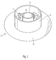
- Fig. 1 The embodiment according to Fig. 1 is in Fig. 2 visible in perspective.
- the inner ring 16 extends according to Fig. 2 about a slightly lower height than the outer ring 18.
- a lid can fit fit over the inner ring 16 in the outer ring 18, so that in conjunction with the bottom 28, a closed annular space 26 results.
- the cross-section of the annulus 26 is substantially square or slightly tall-rectangular with a height-to-width ratio of 1.5 to 1. It should be understood that the dimensions of the inventive molding space 10 are widely adaptable to the requirements. It is also possible to mount the inventive mold space 10 on a turntable 30, which allows a further improved homogenization of the microwave exposure.
- the heating time can be greatly shortened, whereby in experiments a reduction to a little less than half compared to a microwave oven according to the prior art could be realized.
Landscapes
- Physics & Mathematics (AREA)
- Electromagnetism (AREA)
- Dental Prosthetics (AREA)
- Dental Tools And Instruments Or Auxiliary Dental Instruments (AREA)
- Constitution Of High-Frequency Heating (AREA)
Abstract
Description
- Die Erfindung betrifft eine Vorrichtung zur Erwärmung von Formteilen, insbesondere dentalkeramischen Formteilen, in einem Mikrowellenofen, gemäß dem Oberbegriff von Anspruch 1.
- Ein derartiger Ofen ist beispielsweise aus der
EP 1 060 713 A1 bekannt. Bei einem derartigen Ofen werden Dentalkeramiken Mikrowellenstrahlung ausgesetzt, wobei auch Suszeptoren eingesetzt werden können, die die Mikrowellenstrahlung aufnehmen und sich hierdurch aufheizen, wodurch das dentale Formteil ebenfalls aufgeheizt wird. - Die Festigkeit einerseits und die Elastizität andererseits von Dentalkeramiken hängt in starkem Maße von der thermischen Behandlung, insbesondere von der Brenn- bzw. Sinterkurve ab. Während mit einer üblichen Infrarotheizung beaufschlagte Dentalkeramiken typischerweise von außen nach innen sintern, nachdem die abgegebene Wärme durch Wärmestrahlung oder Konvektion dem dentalen Formteil von außen zugeleitet wird, haben Mikrowellen den Vorteil, dass sie dem Grunde nach auch geeignet sind, ein dentales Formteil von innen her aufzuheizen.
- Andererseits besteht bei einem handelsüblichen Mikrowellenofen typischerweise der Nachteil, dass ein starker lokaler Temperaturgradient besteht, weswegen auch bei recht einfachen Mikrowellenöfen Drehteller eingesetzt werden, die entweder das zu erwärmende Gut oder die abgegebene Mikrowellenstrahlung rotieren lassen, um so eine gewisse Vergleichmäßigung zu erzielen.
- Es sind verschiedene Versuche unternommen worden, die Mikrowellenstrahlen in Dentalbrennöfen zu vergleichmäßigen. So sind auch für den Dentalbereich rotierende Drehteller vorgeschlagen worden, wobei die Überprüfungen ergeben haben, dass dennoch die Materialeigenschaften der gesinterten Formteile nicht ganz befriedigend sind.
- Daher ist man bestrebt, die Gleichmäßigkeit der Erwärmung weiter zu verbessern. Hierzu ist es beispielsweise bereits vorgeschlagen worden, besonders dickwandige Suszeptoren einzusetzen, um eine insofern einen höheren Vergleichmäßigungseffekt zu erzielen. Hierdurch wird die Mikrowellenstrahlung in thermische Energie umgewandelt, die ihrerseits das Formteil oder die Formteile von deren Außenseite beaufschlagt, so dass diese Lösung eher einem Brennofen ähnelt, der in klassischer Weise thermisch betrieben wird, aber die Formteile je stets von außen nach innen erwärmt.
- Bei einer derartigen Erwärmung entstehen jedoch zwangsläufig Temperaturgradienten, insbesondere da regelmäßig angestrebt wird, die Zykluszeit beim Brennen gering zu halten, also eine rasche Aufheizung und eine vergleichsweise rasche Abkühlung zu ermöglichen.
- Demgegenüber liegt der Erfindung die Aufgabe zugrunde, eine Vorrichtung zur Erwärmung von Formteilen, insbesondere dentalkeramischen Formteilen, gemäß dem Oberbegriff von Anspruch 1 zu schaffen, die ein verbessertes Restaurationsergebnis ermöglicht, ohne dass eine Verlängerung der Zykluszeit erforderlich wäre, vorzugsweise die Zykluszeit verkürzt werden kann.
- Diese Aufgabe wird erfindungsgemäß durch Anspruch 1 gelöst. Vorteilhafte Weiterbildungen ergeben sich aus den Unteransprüchen.
- Erfindungsgemäß ist es vorgesehen, einen Innenring und einen Außenring aus Suszeptoren um das Formteil herum aufzubauen, wobei das Formteil in dem so gebildeten Ringraum aufgenommen ist. Überraschend ergibt sich durch diese Maßnahme eine gleichmäßigere Erwärmung, was daran liegt, dass durch die großflächigen, aber vergleichsweise dünnwandigen Suszeptoren ein gewisser Anteil der Mikrowellenstrahlung in den Ringraum eindringt und insofern ein Gleichgewicht aus der durch die Suszeptoren abgegebenen Wärmestrahlung und Mikrowellenstrahlung erzeugt wird. Dieses Gleichgewicht führt zur gleichmäßigen Erwärmung des Formteils sowohl von innen als auch von außen, so dass der Temperaturgradient bei richtiger Auslegung von Innenring und Außenring stark reduziert ist, auch wenn mit einer vergleichsweise hohen Leistung und damit einer raschen Aufheizung gearbeitet wird.
- In einer einfachen Ausführungsform sind sowohl Innenring als auch Außenring als hochkant stehende Ringe ausgebildet, zwischen denen sich der Ringraum erstreckt, wobei keiner der beiden Ringe vollständig geschlossen sein muss. In diesem Fall fließen weder im Innenring noch im Außenring nennenswerte Ströme, und beide Ringe wirken als passive Suszeptoren.
- In vorteilhafter Ausgestaltung ist es jedoch auch möglich, die Ringe geschlossen auszubilden und aus einem temperaturfesten Halbleiter aufzubauen, der zugleich Suszeptor für Mikrowellenstrahlung ist. Bei dieser geschlossenen Ringform wird dann Mikrowellenstrahlung induziert und die induzierten Ströme wirken leistungsverbrauchend und setzten insofern Mikrowellenstrahlung zusätzlich in Wärme um. Hierbei wirkt der Halbleiter im Grunde zugleich als Ohm'scher Widerstand, der Verlustwärme abgibt.
- Aufgrund des Ringraums ist es möglich, auch beim gleichzeitigen Brennen zahlreicher Formteile die Suszeptoren recht nahe an den Formteilen anzubringen, so dass die thermische Ankopplung besonders gut ist. Dies führt zu der erwünschten Vergleichmäßigung der Erwärmung aufgrund der kombinierten Wirkung der Wärmestrahlung und der Mikrowellenstrahlung, die je gegenläufige lokale Aufheizprofile haben.
- Erfindungsgemäß besonders günstig ist es, dass die Mikrowellenstrahlung - auch ohne Drehteller - durch die vergleichsweise großen Wandflächen des sich für die Mikrowellenstrahlung als ringförmiger Suszeptor darstellenden Raums für die Aufnahme der Formteile in starkem Maße absorbiert werden kann, wobei es grundsätzlich möglich ist, einen Mikrowellen-Hybridofen zu verwenden, auch wenn dies aufgrund der guten Absorptioseigenschaften nicht unbedingt erforderlich ist. Aufgrund der Teiltransparenz der Suszeptoren für Mikrowellenstrahlung erfolgt dennoch eine Mikrowellenbeaufschlagung auch der Formteile, die dazu dient, das erwünschte thermische Gleichgewicht sicherzustellen.
- In besonders günstiger Ausgestaltung sind die Höhe, aber auch die Durchmesser der Ringe, also des Innenrings und des Außenrings, Vielfache oder Teiler der Wellenlänge der Mikrowellenstrahlung, die von dem Mikrowellengenerator emittiert wird. Beispielsweise kann die Wellenlänge 1 der verwendeten Mikrowellenstrahlung 120mm betragen, und die Höhe sowohl des Innenrings als auch des Außenrings kann dann 120mm, 60mm oder 30mm betragen.
- Es versteht sich, dass sowohl die Wellenlänge als auch dementsprechend die Generatorfrequenz des Mikrowellengenerators in weiten Bereichen an die Erfordernisse anpassbar ist, wobei es aus Kostengründen bevorzugt ist, Standard-Mikrowellengeneratoren mit einer Emissionsfrequenz von 2,45 GHz zu verwenden.
- Bevorzugt sind die Ringe zueinander konzentrisch angeordnet und der sich zwischen ihnen erstreckende Formraum, also der Ringraum für die Aufnahme der Formteile, weist einen kreisringförmigen Boden auf, der zugleich der räumlichen Festlegung der Ringe zueinander dient, oder es sind einzelne Distanzhalter zur Festlegung der Lage der Ringe angebracht.
- Als Suszeptoren können beliebige geeignete Materialien verwendet werden, die bereits bei niedrigen Temperaturen mikrowellenstrahlung-absorbierend wirken. Bevorzugt sind die Suszeptoren teil-absorbierend für Mikrowellenstrahlung, wozu ihre vergleichsweise geringe Wandstärke von höchstens wenigen Millimetern beiträgt. Die Suszeptoren können die Formteile dementsprechend nach der Art eines Gefäßes, also in geschlossener Form umgeben, wobei dennoch die Mikrowellenstrahlung in der gewünschten Weise dem betreffenden Formteil zugeleitet wird.
- Anstelle dessen ist es aber auch möglich, Anschlüsse beispielsweise für die Zu- und Ableitung von Gasen in dem Suszeptor vorzusehen, wobei der kreisringförmige Suszeptor auch nach der Art eines zweiteiligen Gefäßes mit Deckel ausgebildet sein kann.
- Als Materialien für die Ringe können verwendet werden: Siliziumkarbid, Titankarbid, Zirkonkarbid, Hafniumkarbid, Vanadiumkarbid, Tantalkarbid, Molybdänkarbid, Niobkarbid, Siliziumborid, Hafniumborid, Zirkoniumborid, Siliziumnitrid, Zirkoniumnitird, Calciumborid oder Mischungen dieser, aber auch beispielsweise in Kombination mit Al2O3, Si3N4 und/oder BaTi03.
- Erfindungsgemäß besonders günstig ist es, wenn über den Boden des Suszeptors, der sich zwischen dem Innenring und dem Außenring erstreckt, eine gute Wärmeleitung sichergestellt ist, die gewährleistet, dass die von den Ringen absorbierte und in Wärmestrahlung umgewandelte Mikrowellenstrahlung den Formteilen zugeleitet wird. Hierzu ist es günstig, wenn die Ringe je mit dem Boden in thermischer Verbindung stehen.
- Erfindungsgemäß ist es auch günstig, dass sich durch die kombinierte Zuleitung sowohl von thermischer Energie als auch von Mikrowellenenergie die Formteile rascher aufheizen lassen.
- In einer weiteren vorteilhaften Ausgestaltung ist es vorgesehen, dass der Suszeptor einen Ringraum zwischen dem Innenring und dem Außenring aufspannt, dessen radiale Erstreckung im Wesentlichen gleichbleibend ist und insbesondere zwischen dem 0,5-fachen und dem 2-fachen des Durchmessers der Höhe der Ringe beträgt.
- In einer weiteren vorteilhaften Ausgestaltung ist es vorgesehen, dass der Innenring und/oder der Außenring des Suszeptors elliptisch oder kreisförmig ausgebildet ist.
- In einer weiteren vorteilhaften Ausgestaltung ist es vorgesehen, dass sowohl der Innenring als auch der Außenring je einen Querschnitt eines hochkant stehenden Rechtecks aufweisen, wobei die Höhe zwischen 20 und 120% des Durchmessers des Rings beträgt, bevorzugt zwischen 50 und 85% und insbesondere zwischen 65 und 75% des Durchmessers.
- In einer weiteren vorteilhaften Ausgestaltung ist es vorgesehen, dass der Innenring und der Außenring ein insbesondere geschlossenes Gefäß als Wärmebehandlungskammer mit homogenen Temperaturfeld aufspannen, in welchem sich das oder die zu erwärmenden Formteile befinden, wobei das Gefäß insbesondere mindestens teilweise für Mikrowellenstrahlung durchlässig ist.
- In einer weiteren vorteilhaften Ausgestaltung ist es vorgesehen, dass Innenring und Außenring als Suszeptor Mikrowellenstrahlung absorbieren und Wärmestrahlung vergleichmäßigt emittieren.
- In einer weiteren vorteilhaften Ausgestaltung ist es vorgesehen, dass der Innenring und/oder der Außenring je einen geschlossenen Stromkreis bilden und insbesondere als Halbleiter ausgebildet sind.
- In einer weiteren vorteilhaften Ausgestaltung ist es vorgesehen, dass der Suszeptor als Halbleiter ausgebildet ist, und an seiner Oberfläche eine Schutzschicht aus Siliziumdioxid aufweist, die auch elektrisch isolierend wirkt.
- In einer weiteren vorteilhaften Ausgestaltung ist es vorgesehen, dass die ringförmigen Suszeptorelemente des Suszeptors gegeneinander elektrisch isoliert sind und insbesondere auf einer elektrisch isolierenden Oberfläche angeordnet sind.
- In einer weiteren vorteilhaften Ausgestaltung ist es vorgesehen, dass jedes Suszeptorelement eine im Wesentlichen gleichmäßige Höhe und/oder Wandstärke aufweist, die insbesondere die Höhe des Formteils um ein Mehrfaches übersteigt.
- In einer weiteren vorteilhaften Ausgestaltung ist es vorgesehen, dass mindestens ein Suszeptorelement kreissymmetrisch ausgebildet ist und insbesondere um seine Achse drehbar gelagert ist.
- In einer weiteren vorteilhaften Ausgestaltung ist es vorgesehen, dass die Wanddicke eines Suszeptorelements ein Siebzigstel bis ein Vierzigstel der Wellenlänge I der Mikrowellenstrahlung beträgt, die der Mikrowellengenerator erzeugt, und insbesondere zwischen 1,8mm und 2,5mm dick ist.
- In einer weiteren vorteilhaften Ausgestaltung ist es vorgesehen, dass die Höhe jedes Suszeptorelements teilergleich mit der Wellenlänge I des Mikrowellengenerators ist, insbesondere I-Halbe oder I-Viertel beträgt.
- In einer weiteren vorteilhaften Ausgestaltung ist es vorgesehen, dass die Suszeptorelemente konzentrisch zueinander angeordnet sind und insbesondere einstückig miteinander verbunden sind.
- In einer weiteren vorteilhaften Ausgestaltung ist es vorgesehen, dass die Suszeptorelemente über einen kreisringförmigen Boden oder über Distanzhalter miteinander verbunden sind.
- In einer weiteren vorteilhaften Ausgestaltung ist es vorgesehen, dass zwischen den Suszeptorelementen ein kreisringförmiger Raum gebildet ist, der mit einem Kugelbett versehen ist, wobei die Kugeln des Kugelbetts insbesondere aus dichtgesintertem Zirkondioxid und/oder aus Al2O3 bestehen, und/oder dass der Raum Hohl-, Bruchkugeln, Pulver oder sog. Flakes aufweist.
- Weitere Vorteile, Einzelheiten und Merkmale ergeben sich aus der nachfolgenden Beschreibung eines Ausführungsbeispiels der Erfindung anhand der Zeichnungen.
- Es zeigen:
- Fig. 1
- eine schematische Ansicht eines Details einer erfindungsgemäßen Vorrichtung zur Erwärmung von Formteilen in einer ersten Ausführungsform; und
- Fig. 2
- eine perspektivische Ansicht des Details gemäß
Fig. 1 . -
Fig. 1 zeigt eine schematische Ansicht einer erfindungsgemäßen Ausführungsform eines Details der Vorrichtung zur Erwärmung von dentalkeramischen Formteilen, wobei ein Formraum 10 dargestellt ist. Der Formraum 10 nimmt als im Wesentlichen ringförmiger Raum Formteile 12 und 14 auf. Es versteht sich, dass anstelle dessen auch eine beliebige andere Anzahl und Anordnung von Formteilen erfindungsgemäß verwendbar ist. - Der Formraum 10 weist zudem mindestens einen Innenring 16 und einen Außenring 18 auf. Er ist in einem nicht dargestellten Brennofen angeordnet, der von einem Mikrowellengenerator mit Mikrowellenstrahlung beauftragt wird.
- Der Innenring 16 und der Außenring 18 erstrecken sich nach der Art von flachen Zylindern konzentrisch zueinander, wobei bei dem dargestellten Ausführungsbeispiel der Durchmesser des Innenrings 16 etwa ein Drittel des Durchmessers des Außenrings 18 beträgt. Die Höhe des Außenrings beträgt etwa die Hälfte seines Durchmessers, während in dem dargestellten Ausführungsbeispiel die Höhe des Innenrings 16 etwas geringer ist, wie es weiter unten erläutert ist.
- Der Innenring 16 und der Außenring 18 sind bei dem bevorzugten Ausführungsbeispiel aus Siliziumkarbid ausgebildet und wirken insofern als Suszeptoren.
- In dem dargestellten Ausführungsbeispiel sind sowohl der Innenring als auch der Außenring zylindrisch ausgebildet. Es versteht sich, dass es anstelle dessen ohne Weiteres möglich ist, dem Innenring und/oder dem Außenring eine kegelstumpfförmige Gestalt zu geben, oder beispielsweise eine einer Halbkugel angenäherte Form.
- Auch ist es nicht erforderlich, dass die Ringe je in sich vollständig geschlossen sind. Dies gilt insbesondere, wenn vergleichsweise große Wandstärken für die Ringe verwendet werden, wobei durch eine oder mehrere entsprechende Ausnehmungen oder durch die Realisierung von Segmenten der Zutritt von Mikrowellenstrahlung zum Formteil erleichtert ist, wobei es sich versteht, dass eine geschlossene Ausgestaltung die Realisierung einer Induktionsspule ermöglicht.
- Besonders günstig ist es andererseits, wenn durch jeden der Ringe je ein Stromkreis gebildet ist, denn die aufgebrachte Mikrowellenstrahlung induziert dann dort Ströme, die zusätzlich dazu beitragen, thermische Energie zu den Formteilen abzustrahlen.
- Dies ist schematisch in
Fig. 1 dargestellt, wobei die vom Mikrowellengenerator dem Formraum 10 zugeleitete Mikrowellenstrahlung durch den Pfeil 20 angedeutet ist. Der Pfeil 22 zeigt die von dem Außenring 18 als Suszeptor abgegebene Mikrowellenstrahlung, während der Pfeil 24 die von dem Suszeptor 18 an das Formteil 14 abgegebene Wärmestrahlung zeigt. - Beim Aufheizen des Dentalbrennofens wirken die Suszeptoren 16 und 18 in an sich bekannter Weise als Mikrowellenrezeptoren, während ein beispielsweise aus Zirkondioxid bestehendes Formteil 14 erst bei Temperaturen oberhalb von etwa 700°C ankoppelt und dann einfallende Mikrowellen absorbiert.
- Bevorzugt ist, dass das Material, das für den Außenring 18 und den Innenring 16 verwendet wird, so beschaffen ist, dass es teiltransparent für Mikrowellen ist. Bevorzugt wird hierzu ein offenporiges Siliziumkarbid verwendet, das auch rekristallisiert sein kann und eine vergleichsweise grobe Kristallstruktur und eine raue Oberfläche aufweist. Die Porosität beträgt bevorzugt zwischen 5 und 15%, insbesondere etwa 10%, und die Dichte um 90%, wobei auch Werte zwischen 85 und 95% TD die erwünschten Wirkung zeitigen.
- Es versteht sich, dass in einer modifizierten Augestaltung der erfindungsgemäßen Suszeptoren auch eine Porosität von bis zu 25% erfolgreich eingesetzt werden kann.
- Siliziumkarbid ist einerseits chemisch inert und besitzt andererseits einen hohen dielektrischen Verlustfaktor. Erfindungsgemäß wird jedoch ebenfalls bevorzugt die Tatsache ausgenutzt, dass Siliziumkarbid auch ein Halbleiter ist. Die induzierten Ströme generieren damit eine elektrische Verlustleistung in dem materialspezifisch bestehenden Innenwiderstand des Suszeptors.
- Bevorzugt weist der Innenring, aber auch der Außenring, eine ausgesprochen geringe Wandstärke auf, beispielsweise um 2mm. Bei einer derartigen Wandstärke ist die mechanische Festigkeit noch in ausreichendem Maße gegeben. Die Durchlässigkeit für die Mikrowellenstrahlung ist jedoch ebenfalls in der erwünschten Weise gegeben, und insbesondere ist der elektrische Widerstand höher als bei größeren Wandstärken.
- Erfindungsgemäß besonders günstig ist sowohl das Formteil 12 als auch das Formteil 14 in dem Ringraum angeordnet, der zwischen dem Innenring 16 und dem Außenring 18 aufgespannt ist. Diese Anordnung erhöht überraschend signifikant die Gleichmäßigkeit der Temperaturverteilung bei der Erwärmung im Dentalbrennofen, der primär mit Mikrowellenstrahlung betrieben wird. Trotz der runden und insofern gleichmäßig beaufschlagbaren Gesamtausgestaltung des Formraums lassen sich die Formteile optimal auch mit thermischer Energie versorgen, die ausgleichend bei der Erwärmung der Formteile wirkt.
- In der Ausführungsform gemäß
Fig. 1 sind zwei Formteile 12 und 14 in dem Ringraum 26 zwischen dem Innenring 16 und dem Außenring 18 aufgenommen. Die Abmessungen sind so gewählt, dass auch die größten vorkommenden Dentalersatzteile in den Ringraum 26 aufgenommen werden können. Hierbei ist es besonders günstig, wenn einmal ein sehr großes, dem menschlichen Kiefer folgend ausgebildetes, also insofern im Wesentlichen U-förmiges Formteil gebrannt werden soll, dieses so eingelegt werden kann, dass es sich beidseitig des Innenrings 16 erstreckt. - Der Ringraum 26 ist bevorzugt mit einem Boden versehen, der aus dem gleichen Material wie die Ringe 16 und 18 besteht. Wenn Siliziumkarbid verwendet wird, lässt sich hierbei die Tatsache ausnutzen, dass die Oberfläche von Siliziumkarbid typischerweise zu Siliziumdioxid oxidiert, das elektrisch nicht leitend ist, so dass sich zwischen dem Innenring 16 und dem Boden 28 einerseits und dem Boden 28 und dem Außenring 18 andererseits eine Isolierung ergibt.
- In der Ausführungsform gemäß
Fig. 1 sind die Formteile 12 und 14 auf einem Kugelbett aufgenommen, das entweder aus Zirkondioxid-Kugeln bestehen kann, oder aus einem mikrowellen-transparenten Isolationsmaterial, wobei auch auch Al2O3 oder beispielsweise Si3N4 eingesetzt werden können. - Die Ausführungsform gemäß
Fig. 1 ist inFig. 2 in perspektivischer Darstellung ersichtlich. Der Innenring 16 erstreckt sich gemäßFig. 2 über eine etwas geringere Höhe als der Außenring 18. Ein hier nicht dargestellter Deckel lässt sich passgenau über dem Innenring 16 in den Außenring 18 einfügen, so dass sich in Verbindung mit dem Boden 28 ein geschlossener Ringraum 26 ergibt. - Der Querschnitt des Ringraums 26 ist im Wesentlichen quadratisch oder etwas hoch-rechteckig mit einem Höhen-Breiten-Verhältnis von 1,5 zu 1. Es versteht sich, dass die Abmessungen des erfindungsgemäßen Formraums 10 in weiten Bereichen an die Erfordernisse anpassbar sind. Auch ist es möglich, den erfindungsgemäßen Formraum 10 auf einem Drehteller 30 zu lagern, der eine noch verbesserte Vergleichmäßigung der Mikrowellenbeaufschlagung ermöglicht.
- Durch die enge Anbindung des Dentalgerüsts an als Suszeptoren wirkenden Ringe 16 und 18 lässt sich die Aufheizzeit stark verkürzen, wobei in Versuchen eine Reduktion auf etwas weniger als die Hälfte gegenüber einem Mikrowellenofen gemäß dem Stand der Technik realisiert werden konnte.
Claims (15)
- Vorrichtung zur Erwärmung von Formteilen, insbesondere dentalkeramischen Formteilen, mit einem Mikrowellengenerator, der einen Suszeptor mit Mikrowellenstrahlung beaufschlagt, welcher Suszeptor zwischen dem Formteil und dem Mikrowellengenerator angeordnet ist, dadurch gekennzeichnet, dass der Suszeptor mindestens teilweise sowohl einen Innenring (16) als auch einen Außenring (18) bildet und dass das Formteil (12, 14) zwischen Innenring (16) und Außenring (18) angeordnet ist.
- Vorrichtung nach einem der vorhergehenden Ansprüche, dadurch gekennzeichnet, dass der Suszeptor einen Ringraum (26) zwischen dem Innenring (16) und dem Außenring (18) aufspannt, dessen radiale Erstreckung im Wesentlichen gleichbleibend ist und insbesondere zwischen dem 0,5-fachen und dem 2-fachen des Durchmessers der Höhe der Ringe beträgt.
- Vorrichtung nach einem der vorhergehenden Ansprüche, dadurch gekennzeichnet, dass der Innenring (16) und/oder der Außenring (18) des Suszeptors elliptisch oder kreisförmig ausgebildet ist.
- Vorrichtung nach einem der vorhergehenden Ansprüche, dadurch gekennzeichnet, dass sowohl der Innenring (16) als auch der Außenring (18) je einen Querschnitt eines hochkant stehenden Rechtecks aufweisen, wobei die Höhe zwischen 20 und 120% des Durchmessers des Rings beträgt, bevorzugt zwischen 50 und 85% und insbesondere zwischen 65 und 75% des Durchmessers.
- Vorrichtung nach einem der vorhergehenden Ansprüche, dadurch gekennzeichnet, dass der Innenring (16) und der Außenring (18) ein insbesondere geschlossenes Gefäß als Wärmebehandlungskammer mit homogenen Temperaturfeld aufspannen, in welchem sich das oder die zu erwärmenden Formteile (12, 14) befinden, wobei das Gefäß insbesondere mindestens teilweise für Mikrowellenstrahlung durchlässig ist.
- Vorrichtung nach einem der vorhergehenden Ansprüche, dadurch gekennzeichnet, dass Innenring (16) und Außenring (18) als Suszeptor Mikrowellenstrahlung absorbieren und Wärmestrahlung vergleichmäßigt emittieren.
- Vorrichtung nach einem der vorhergehenden Ansprüche, dadurch gekennzeichnet, dass der Innenring (16) und/oder der Außenring (18) je einen geschlossenen Stromkreis bilden und insbesondere als Halbleiter ausgebildet sind.
- Vorrichtung nach Anspruch 7, dadurch gekennzeichnet, dass der Suszeptor als Halbleiter ausgebildet ist, und an seiner Oberfläche eine Schutzschicht aus Siliziumdioxid aufweist, die auch elektrisch isolierend wirkt.
- Vorrichtung nach einem der vorhergehenden Ansprüche, dadurch gekennzeichnet, dass die ringförmigen Suszeptorelemente des Suszeptors gegeneinander elektrisch isoliert sind und insbesondere auf einer elektrisch isolierenden Oberfläche angeordnet sind.
- Vorrichtung nach einem der vorhergehenden Ansprüche, dadurch gekennzeichnet, dass jedes Suszeptorelement eine im Wesentlichen gleichmäßige Höhe und/oder Wandstärke aufweist, die insbesondere die Höhe des Formteils (12, 14) um ein Mehrfaches übersteigt.
- Vorrichtung nach einem der vorhergehenden Ansprüche, dadurch gekennzeichnet, dass mindestens ein Suszeptorelement kreissymmetrisch ausgebildet ist und insbesondere um seine Achse drehbar gelagert ist.
- Vorrichtung nach einem der vorhergehenden Ansprüche, dadurch gekennzeichnet, dass die Wanddicke eines Suszeptorelements (16, 18) ein Siebzigstel bis ein Vierzigstel der Wellenlänge I der Mikrowellenstrahlung beträgt, die der Mikrowellengenerator erzeugt, und insbesondere zwischen 1,8mm und 2,5mm dick ist.
- Vorrichtung nach einem der vorhergehenden Ansprüche, dadurch gekennzeichnet, dass die Höhe jedes Suszeptorelements (16, 18) teilergleich mit der Wellenlänge I des Mikrowellengenerators ist, insbesondere I-Halbe oder I-Viertel beträgt.
- Vorrichtung nach einem der vorhergehenden Ansprüche, dadurch gekennzeichnet, dass die Suszeptorelemente (16, 18) konzentrisch zueinander angeordnet sind und insbesondere einstückig miteinander verbunden sind.
- Vorrichtung nach einem der vorhergehenden Ansprüche, dadurch gekennzeichnet, dass die Suszeptorelemente (16, 18) über einen kreisringförmigen Boden (30) oder über Distanzhalter miteinander verbunden sind und/oder dass zwischen den Suszeptorelementen (16, 18) ein kreisringförmiger Raum (26) gebildet ist, der mit einem Kugelbett versehen ist, wobei die Kugeln des Kugelbetts insbesondere aus dichtgesintertem Zirkondioxid und/oder aus Al2O3 bestehen, und/oder dass der Raum (26) Hohl-, Bruchkugeln, Pulver oder sog. Flakes aufweist.
Applications Claiming Priority (1)
| Application Number | Priority Date | Filing Date | Title |
|---|---|---|---|
| DE102008035235.7A DE102008035235B4 (de) | 2008-07-29 | 2008-07-29 | Vorrichtung zur Erwärmung von Formteilen, insbesondere dentalkeramischen Formteilen |
Publications (3)
| Publication Number | Publication Date |
|---|---|
| EP2150092A2 true EP2150092A2 (de) | 2010-02-03 |
| EP2150092A3 EP2150092A3 (de) | 2011-01-26 |
| EP2150092B1 EP2150092B1 (de) | 2012-11-21 |
Family
ID=41226714
Family Applications (1)
| Application Number | Title | Priority Date | Filing Date |
|---|---|---|---|
| EP09164746A Not-in-force EP2150092B1 (de) | 2008-07-29 | 2009-07-07 | Vorrichtung zur Erwärmung von Formteilen, insbesondere dentalkeramischen Formteilen |
Country Status (4)
| Country | Link |
|---|---|
| US (1) | US20100025395A1 (de) |
| EP (1) | EP2150092B1 (de) |
| JP (1) | JP5162057B2 (de) |
| DE (1) | DE102008035235B4 (de) |
Cited By (2)
| Publication number | Priority date | Publication date | Assignee | Title |
|---|---|---|---|---|
| US20120012577A1 (en) * | 2010-07-16 | 2012-01-19 | Ivoclar Vivadent, Ag | Microwave Oven Comprising A Rotary Table |
| EP2437020A1 (de) | 2010-10-01 | 2012-04-04 | Ivoclar Vivadent AG | Mikrowellenofen |
Families Citing this family (8)
| Publication number | Priority date | Publication date | Assignee | Title |
|---|---|---|---|---|
| DE102008035240B4 (de) * | 2008-07-29 | 2017-07-06 | Ivoclar Vivadent Ag | Vorrichtung zur Erwärmung von Formteilen, insbesondere dentalkeramischen Formteilen |
| CN103261824A (zh) * | 2010-10-07 | 2013-08-21 | 米尔特·D·马蒂斯 | 微波回转窑 |
| EP2452651A1 (de) * | 2010-11-15 | 2012-05-16 | Ivoclar Vivadent AG | Dentalofen mit Suszeptor-Behälter |
| US9759487B2 (en) | 2011-03-02 | 2017-09-12 | Ivoclar Vivadent Ag | Dental firing or press furnace |
| ES2528005T3 (es) * | 2011-03-02 | 2015-02-03 | Ivoclar Vivadent Ag | Horno dental de cocción o de prensado |
| US10882071B2 (en) * | 2015-03-27 | 2021-01-05 | Centre National De La Recherche Scientifique | Method for thermal treatment of a surface coating on a metal part by microwaves |
| US11435142B2 (en) * | 2015-12-16 | 2022-09-06 | 3M Innovative Properties Company | Microwave furnace and a method of sintering |
| DE102017118660A1 (de) * | 2017-08-16 | 2019-02-21 | Homag Gmbh | Applikator zum thermischen Aktivieren einer Funktionsschicht eines Beschichtungsmaterials |
Citations (3)
| Publication number | Priority date | Publication date | Assignee | Title |
|---|---|---|---|---|
| EP1060713A1 (de) | 1999-06-17 | 2000-12-20 | Wieland Edelmetalle GmbH & Co. | Verfahren zur Herstellung von Dentalkeramiken sowie Ofen zur Wärmebehandlung von Dentalkeramiken |
| US20020168283A1 (en) | 2001-05-14 | 2002-11-14 | Morrow Marvin S. | Microwave processing of pressed boron powders for use as cathodes in vacuum arc sources |
| US20070023971A1 (en) | 2004-09-01 | 2007-02-01 | Subrata Saha | Method of microwave processing ceramics and microwave hybrid heating system for same |
Family Cites Families (93)
| Publication number | Priority date | Publication date | Assignee | Title |
|---|---|---|---|---|
| US3049432A (en) * | 1959-03-04 | 1962-08-14 | Berthold C Weber | Crucible and refractory material therefor |
| GB1032297A (en) * | 1962-06-12 | 1966-06-08 | Gen Dynamics Corp | Improvements in or relating to refractory carbides |
| US3520656A (en) * | 1966-03-30 | 1970-07-14 | Du Pont | Silicon carbide compositions |
| US3477872A (en) * | 1966-09-21 | 1969-11-11 | Rca Corp | Method of depositing refractory metals |
| US3519504A (en) * | 1967-01-13 | 1970-07-07 | Ibm | Method for etching silicon nitride films with sharp edge definition |
| US3574014A (en) * | 1967-07-24 | 1971-04-06 | Frances Hugle | Masking technique for selective etching |
| US3658586A (en) * | 1969-04-11 | 1972-04-25 | Rca Corp | Epitaxial silicon on hydrogen magnesium aluminate spinel single crystals |
| US3597269A (en) * | 1969-09-30 | 1971-08-03 | Westinghouse Electric Corp | Surfce stabilization of semiconductor power devices and article |
| SE368269B (de) * | 1970-08-18 | 1974-06-24 | Hirst Microwave Ind Ltd | |
| US3702786A (en) * | 1970-10-28 | 1972-11-14 | Rca Corp | Mos transistor with aluminum oxide gate dielectric |
| US3785862A (en) * | 1970-12-14 | 1974-01-15 | Rca Corp | Method for depositing refractory metals |
| US3697343A (en) * | 1970-12-16 | 1972-10-10 | Ibm | Method of selective chemical vapor deposition |
| US3972704A (en) * | 1971-04-19 | 1976-08-03 | Sherwood Refractories, Inc. | Apparatus for making vitreous silica receptacles |
| GB1384319A (en) * | 1971-04-19 | 1975-02-19 | Sherwood Refractories | Vitreous silica and process and apparatus for making same |
| GB1359896A (en) * | 1972-01-19 | 1974-07-17 | Rolls Royce | Method and apparatus for manufacturing bladed members from powder material |
| US3766637A (en) * | 1972-05-04 | 1973-10-23 | Rca Corp | Method of making mos transistors |
| US3853612A (en) * | 1973-09-10 | 1974-12-10 | Owens Illinois Inc | Method for making coated receptacle for microwave cooking of food |
| US4190439A (en) * | 1973-12-28 | 1980-02-26 | Union Carbide Corporation | Process for the preparation of fine grain metal carbide powders and sintered articles therefrom |
| US3932594A (en) * | 1973-12-28 | 1976-01-13 | Union Carbide Corporation | Process for the preparation of fine grain metal carbide powders |
| US4006045A (en) * | 1974-10-21 | 1977-02-01 | International Business Machines Corporation | Method for producing high power semiconductor device using anodic treatment and enhanced diffusion |
| US4190757A (en) * | 1976-10-08 | 1980-02-26 | The Pillsbury Company | Microwave heating package and method |
| US4362917A (en) * | 1980-12-29 | 1982-12-07 | Raytheon Company | Ferrite heating apparatus |
| US4697330A (en) * | 1983-02-23 | 1987-10-06 | Texas Instruments Incorporated | Floating gate memory process with improved dielectric |
| US4529621A (en) * | 1983-10-05 | 1985-07-16 | Utah Computer Industries, Inc. | Process for depositing a thin-film layer of magnetic material onto an insulative dielectric layer of a semiconductor substrate |
| EP0248048B1 (de) * | 1985-11-27 | 1990-09-19 | Cbl Ceramics Limited | Beryllium Oxid Keramik |
| US5603983A (en) * | 1986-03-24 | 1997-02-18 | Ensci Inc | Process for the production of conductive and magnetic transitin metal oxide coated three dimensional substrates |
| US5352517A (en) * | 1986-03-24 | 1994-10-04 | Ensci, Inc. | Iron oxide coated substrates |
| US5290589A (en) * | 1986-03-24 | 1994-03-01 | Ensci, Inc. | Process for coating a substrate with iron oxide and uses for coated substrates |
| JPS632330A (ja) * | 1986-06-23 | 1988-01-07 | Fujitsu Ltd | 化学気相成長方法 |
| US4689458A (en) * | 1986-07-21 | 1987-08-25 | Aluminum Co. Of America | Container system for microwave cooking |
| US4968865A (en) * | 1987-06-01 | 1990-11-06 | General Mills, Inc. | Ceramic gels with salt for microwave heating susceptor |
| US4806718A (en) * | 1987-06-01 | 1989-02-21 | General Mills, Inc. | Ceramic gels with salt for microwave heating susceptor |
| US4927991A (en) * | 1987-11-10 | 1990-05-22 | The Pillsbury Company | Susceptor in combination with grid for microwave oven package |
| US5006684A (en) * | 1987-11-10 | 1991-04-09 | The Pillsbury Company | Apparatus for heating a food item in a microwave oven having heater regions in combination with a reflective lattice structure |
| CA1313231C (en) * | 1987-11-18 | 1993-01-26 | Richard M. Keefer | Microwave heating |
| US4933193A (en) * | 1987-12-11 | 1990-06-12 | E. I. Du Pont De Nemours And Company | Microwave cooking package |
| US4972059A (en) * | 1988-02-29 | 1990-11-20 | The Pillsbury Company | Method and apparatus for adjusting the temperature profile of food products during microwave heating |
| KR0145302B1 (ko) * | 1988-04-28 | 1998-08-17 | 카자마 젠쥬 | 얇은 막의 형성방법 |
| US5194408A (en) * | 1989-02-22 | 1993-03-16 | General Mills, Inc. | Sintered ceramic microwave heating susceptor |
| JPH02275777A (ja) * | 1989-04-17 | 1990-11-09 | Sumitomo Cement Co Ltd | 陶磁器等のセラミックス体とその製造方法および焼成炉 |
| US4959120A (en) * | 1989-06-21 | 1990-09-25 | Golden Valley Microwave Foods, Inc. | Demetallization of metal films |
| US5692635A (en) * | 1990-06-06 | 1997-12-02 | American National Can Company | Easy open closure |
| US5247149A (en) * | 1991-08-28 | 1993-09-21 | The Stouffer Corporation | Method and appliance for cooking a frozen pizza pie with microwave energy |
| EP0570720A1 (de) * | 1992-05-20 | 1993-11-24 | Sumitomo Electric Industries, Ltd. | Leitendes oder superleitendes stabilisiertes Kohlenstoff-Cluster-Material sowie Herstellung und Verwendung |
| US5227600A (en) * | 1992-07-31 | 1993-07-13 | The United States Of America As Represented By The United States Department Of Energy | Microwave sintering of multiple articles |
| JP3233300B2 (ja) * | 1992-12-01 | 2001-11-26 | 株式会社豊田中央研究所 | マイクロ波による焼結方法 |
| US5674792A (en) * | 1993-11-12 | 1997-10-07 | Heraeus Quarzglas Gmbh | Shaped body having a high silicon dioxide content and a process for producing such shaped bodies |
| US5397879A (en) * | 1993-11-17 | 1995-03-14 | National Presto Industries, Inc. | Microwave corn popper device and method |
| CA2124093C (en) * | 1994-03-31 | 2001-04-17 | Prasad S. Apte | Microwave sintering process |
| US5645748A (en) * | 1994-10-07 | 1997-07-08 | Quiclave, L.L.C. | System for simultaneous microwave sterilization of multiple medical instruments |
| US5552112A (en) * | 1995-01-26 | 1996-09-03 | Quiclave, Llc | Method and system for sterilizing medical instruments |
| US5593610A (en) * | 1995-08-04 | 1997-01-14 | Hormel Foods Corporation | Container for active microwave heating |
| WO1998008750A1 (en) * | 1996-08-26 | 1998-03-05 | Fort James Corporation | Microwavable container |
| US6888116B2 (en) * | 1997-04-04 | 2005-05-03 | Robert C. Dalton | Field concentrators for artificial dielectric systems and devices |
| WO1998046046A1 (en) * | 1997-04-04 | 1998-10-15 | Dalton Robert C | Artificial dielectric device for heating gases with electromagnetic energy |
| KR100652909B1 (ko) * | 1998-03-06 | 2006-12-01 | 에이에스엠 아메리카, 인코포레이티드 | 하이 스텝 커버리지를 갖는 실리콘 증착 방법 |
| USD426427S (en) * | 1998-10-02 | 2000-06-13 | Bestfoods | Bowl |
| US6147337A (en) * | 1998-12-10 | 2000-11-14 | Aladdin Industries, Llc | Microwaveable heat retentive receptacle |
| US6316797B1 (en) * | 1999-02-19 | 2001-11-13 | Advanced Technology Materials, Inc. | Scalable lead zirconium titanate(PZT) thin film material and deposition method, and ferroelectric memory device structures comprising such thin film material |
| US6403750B1 (en) * | 1999-06-03 | 2002-06-11 | Edward J. A. Pope | Apparatus and process for making ceramic composites from photo-curable pre-ceramic polymers |
| DE10015614B4 (de) * | 2000-03-29 | 2009-02-19 | Ceramtec Ag | Gesinterter Formkörper mit poröser Schicht auf der Oberfläche sowie Verfahren zu seiner Herstellung und seine Verwendungen |
| US6777253B2 (en) * | 2000-12-20 | 2004-08-17 | Matsushita Electric Industrial Co., Ltd. | Method for fabricating semiconductor, method for fabricating semiconductor substrate, and semiconductor light emitting device |
| US20020106611A1 (en) * | 2001-01-19 | 2002-08-08 | Sutapa Bhaduri | Metal part having a dense core and porous periphery, biocompatible prosthesis and microwave sintering |
| US6717121B2 (en) * | 2001-09-28 | 2004-04-06 | Graphic Packaging International, Inc. | Patterned microwave susceptor element and microwave container incorporating same |
| KR100451447B1 (ko) * | 2001-11-29 | 2004-10-06 | 주성엔지니어링(주) | 서셉터의 전원 인터페이스 어셈블리 |
| JP2003188254A (ja) * | 2001-12-18 | 2003-07-04 | Hitachi Ltd | 半導体装置の製造方法および半導体装置 |
| US20030160044A1 (en) * | 2002-02-25 | 2003-08-28 | Besmann Theodore M. | High efficiency, oxidation resistant radio frequency susceptor |
| CA2501249C (en) * | 2002-10-08 | 2011-02-01 | Graphic Packaging International, Inc. | Container having a rim or other feature encapsulated by or formed from injection-molded material |
| US20070267409A1 (en) * | 2002-10-16 | 2007-11-22 | Coffee Technologies International Inc. | Assembled container for roasting food |
| JP4068072B2 (ja) * | 2003-01-29 | 2008-03-26 | Necエレクトロニクス株式会社 | 半導体装置及びその製造方法 |
| EP1665889A4 (de) * | 2003-09-10 | 2009-06-03 | Univ Alfred Res | Verfahren für mikrowellenbearbeitung von keramik und mikrowellen-hybridheizsystem dafür |
| US7112769B2 (en) * | 2003-10-27 | 2006-09-26 | Alfred University | Susceptor for hybrid microwave sintering system, hybrid microwave sintering system including same and method for sintering ceramic members using the hybrid microwave sintering system |
| JP4387159B2 (ja) * | 2003-10-28 | 2009-12-16 | 東洋炭素株式会社 | 黒鉛材料、炭素繊維強化炭素複合材料、及び、膨張黒鉛シート |
| JP4327205B2 (ja) * | 2004-02-09 | 2009-09-09 | グラフィック パッケージング インターナショナル インコーポレイテッド | 電子レンジ調理用パッケージ |
| US7304010B2 (en) * | 2004-02-23 | 2007-12-04 | Kyocera Corporation | Aluminum oxide sintered body, and members using same for semiconductor and liquid crystal manufacturing apparatuses |
| US8026464B2 (en) * | 2004-03-01 | 2011-09-27 | Nestec S.A. | Multi-purpose food preparation kit |
| US20050261795A1 (en) * | 2004-05-21 | 2005-11-24 | Eastman Kodak Company | Method of making ceramic dental restorations |
| EP1754397A1 (de) * | 2004-06-08 | 2007-02-21 | Truimf, Operating As A Joint Venture By The Gove Ment Of The University Of Alberta | Verfahren zur bildung zusammengesetzter keramischer targets |
| KR100552820B1 (ko) * | 2004-09-17 | 2006-02-21 | 동부아남반도체 주식회사 | 반도체 소자의 제조 방법 |
| EP1841668B1 (de) * | 2005-01-14 | 2009-04-22 | Graphic Packaging International, Inc. | Verpackung zum goldbraunen und knusprigen aufbacken teigbasierter lebensmittel in einem mikrowellenherd |
| ATE499314T1 (de) * | 2005-05-25 | 2011-03-15 | Graphic Packaging Int Inc | Mikrowellenverpackung für aus mehreren komponenten bestehende mahlzeiten |
| US20070092609A1 (en) * | 2005-10-26 | 2007-04-26 | H. J. Heinz Company | Food container |
| US8680448B2 (en) * | 2006-05-15 | 2014-03-25 | Graphic Packaging International, Inc. | Microwavable construct with contoured heating surface |
| WO2008049048A2 (en) * | 2006-10-18 | 2008-04-24 | Graphic Packaging International, Inc. | Tool for forming a three dimensional article or container |
| JP5048998B2 (ja) * | 2006-11-16 | 2012-10-17 | 株式会社松風 | セラミックス用マイクロ波加熱装置及びその発熱体 |
| US8193472B2 (en) * | 2007-03-23 | 2012-06-05 | Nihon Dennetsu Co., Ltd. | Susceptor |
| US20090079101A1 (en) * | 2007-04-27 | 2009-03-26 | Jurgen Laubersheimer | Densification Process of Ceramics And Apparatus Therefor |
| US20090042705A1 (en) * | 2007-08-09 | 2009-02-12 | Albert Vincent Maslowski | Multi-Compartment Microwaveable Food Container |
| EP2245376B1 (de) * | 2008-02-18 | 2014-10-15 | Graphic Packaging International, Inc. | Vorrichtung für die zubereitung eines nahrungsmittels in einem mikrowellenherd |
| ES2451517T3 (es) * | 2008-07-11 | 2014-03-27 | Graphic Packaging International, Inc. | Recipiente para calentamiento por microondas |
| EP2407122B1 (de) * | 2010-07-16 | 2016-07-06 | Ivoclar Vivadent AG | Mikrowellenofen mit Drehteller |
| EP2437020B1 (de) * | 2010-10-01 | 2015-08-12 | Ivoclar Vivadent AG | Mikrowellenofen |
| EP2452651A1 (de) * | 2010-11-15 | 2012-05-16 | Ivoclar Vivadent AG | Dentalofen mit Suszeptor-Behälter |
-
2008
- 2008-07-29 DE DE102008035235.7A patent/DE102008035235B4/de not_active Expired - Fee Related
-
2009
- 2009-06-08 US US12/455,828 patent/US20100025395A1/en not_active Abandoned
- 2009-07-07 EP EP09164746A patent/EP2150092B1/de not_active Not-in-force
- 2009-07-29 JP JP2009177124A patent/JP5162057B2/ja not_active Expired - Fee Related
Patent Citations (3)
| Publication number | Priority date | Publication date | Assignee | Title |
|---|---|---|---|---|
| EP1060713A1 (de) | 1999-06-17 | 2000-12-20 | Wieland Edelmetalle GmbH & Co. | Verfahren zur Herstellung von Dentalkeramiken sowie Ofen zur Wärmebehandlung von Dentalkeramiken |
| US20020168283A1 (en) | 2001-05-14 | 2002-11-14 | Morrow Marvin S. | Microwave processing of pressed boron powders for use as cathodes in vacuum arc sources |
| US20070023971A1 (en) | 2004-09-01 | 2007-02-01 | Subrata Saha | Method of microwave processing ceramics and microwave hybrid heating system for same |
Cited By (3)
| Publication number | Priority date | Publication date | Assignee | Title |
|---|---|---|---|---|
| US20120012577A1 (en) * | 2010-07-16 | 2012-01-19 | Ivoclar Vivadent, Ag | Microwave Oven Comprising A Rotary Table |
| EP2437020A1 (de) | 2010-10-01 | 2012-04-04 | Ivoclar Vivadent AG | Mikrowellenofen |
| US9228782B2 (en) | 2010-10-01 | 2016-01-05 | Ivoclar Vivadent Ag | Microwave oven |
Also Published As
| Publication number | Publication date |
|---|---|
| JP2010029666A (ja) | 2010-02-12 |
| US20100025395A1 (en) | 2010-02-04 |
| EP2150092B1 (de) | 2012-11-21 |
| JP5162057B2 (ja) | 2013-03-13 |
| DE102008035235A1 (de) | 2010-03-11 |
| DE102008035235B4 (de) | 2014-05-22 |
| EP2150092A3 (de) | 2011-01-26 |
Similar Documents
| Publication | Publication Date | Title |
|---|---|---|
| EP2150092B1 (de) | Vorrichtung zur Erwärmung von Formteilen, insbesondere dentalkeramischen Formteilen | |
| EP2098188B1 (de) | Verfahren zum Sintern eines Dentalmaterials | |
| EP2652160B1 (de) | Heizvorrichtung | |
| EP3256804B1 (de) | Sinterofen für bauteile aus sinterwerkstoff, insbesondere dentalbauteile | |
| DE102008035240B4 (de) | Vorrichtung zur Erwärmung von Formteilen, insbesondere dentalkeramischen Formteilen | |
| EP2101547B1 (de) | Dental-Sinterofen sowie Verfahren zum Sintern keramischer Dental-Elemente | |
| EP2452651A1 (de) | Dentalofen mit Suszeptor-Behälter | |
| EP2407122A1 (de) | Mikrowellenofen mit Drehteller | |
| DE202015009956U1 (de) | Dentalsinterofen für Bauteile aus Sinterwerkstoff, insbesondere Dentalbauteile | |
| DE2451253A1 (de) | Verfahren zum sintern keramischer erzeugnisse und vorrichtung zur durchfuehrung des verfahrens | |
| EP0416335B1 (de) | Temperaturschalter | |
| EP2098189A1 (de) | Dentalofen | |
| EP3557172A1 (de) | Dentalofen | |
| DE202007019030U1 (de) | Hybridofen | |
| DE102010011156B4 (de) | Vorrichtung zur thermischen Behandlung von Halbleitersubstraten | |
| DE19923197C2 (de) | Verfahren und Vorrichtung zum Sintern einer Charge von Preßkörpern aus Partikeln | |
| US6399012B1 (en) | Production of passive devices | |
| DE1765672C3 (de) | Niederfrequenz-Induktionserhitzer für die Wärmebehandlung von Blöcken aus Eisenwerkstoff | |
| EP4321060A1 (de) | Geschirr für mikrowellen | |
| DE702140C (de) | Regelbarer elektrischer Kondensator, insbesondere fuer Fernregelung | |
| DE1083454B (de) | Vorrichtung zum Erhitzen von Koerpern vorzugsweise auf Temperaturen von ueber 2000íµ | |
| EP1324635A2 (de) | Mikrowellenofensystem | |
| DE2126614C3 (de) | Kochmulde | |
| DE3800676A1 (de) | Heizvorrichtung, insbesondere als kochplatte | |
| DE2453169C3 (de) | Induktionskochgerät |
Legal Events
| Date | Code | Title | Description |
|---|---|---|---|
| PUAI | Public reference made under article 153(3) epc to a published international application that has entered the european phase |
Free format text: ORIGINAL CODE: 0009012 |
|
| AK | Designated contracting states |
Kind code of ref document: A2 Designated state(s): AT BE BG CH CY CZ DE DK EE ES FI FR GB GR HR HU IE IS IT LI LT LU LV MC MK MT NL NO PL PT RO SE SI SK SM TR |
|
| AX | Request for extension of the european patent |
Extension state: AL BA RS |
|
| PUAL | Search report despatched |
Free format text: ORIGINAL CODE: 0009013 |
|
| AK | Designated contracting states |
Kind code of ref document: A3 Designated state(s): AT BE BG CH CY CZ DE DK EE ES FI FR GB GR HR HU IE IS IT LI LT LU LV MC MK MT NL NO PL PT RO SE SI SK SM TR |
|
| AX | Request for extension of the european patent |
Extension state: AL BA RS |
|
| 17P | Request for examination filed |
Effective date: 20110221 |
|
| GRAP | Despatch of communication of intention to grant a patent |
Free format text: ORIGINAL CODE: EPIDOSNIGR1 |
|
| GRAS | Grant fee paid |
Free format text: ORIGINAL CODE: EPIDOSNIGR3 |
|
| GRAA | (expected) grant |
Free format text: ORIGINAL CODE: 0009210 |
|
| RIN1 | Information on inventor provided before grant (corrected) |
Inventor name: LAUTENSCHLAEGER, WERNER Inventor name: LAUBERSHEIMER, JUERGEN DR. Inventor name: JUSSEL, RUDOLF Inventor name: WERLING, CHRISTIAN |
|
| AK | Designated contracting states |
Kind code of ref document: B1 Designated state(s): AT BE BG CH CY CZ DE DK EE ES FI FR GB GR HR HU IE IS IT LI LT LU LV MC MK MT NL NO PL PT RO SE SI SK SM TR |
|
| REG | Reference to a national code |
Ref country code: GB Ref legal event code: FG4D Free format text: NOT ENGLISH |
|
| REG | Reference to a national code |
Ref country code: CH Ref legal event code: EP Ref country code: CH Ref legal event code: NV Representative=s name: KELLER AND PARTNER PATENTANWAELTE AG, CH |
|
| REG | Reference to a national code |
Ref country code: AT Ref legal event code: REF Ref document number: 585627 Country of ref document: AT Kind code of ref document: T Effective date: 20121215 |
|
| REG | Reference to a national code |
Ref country code: IE Ref legal event code: FG4D Free format text: LANGUAGE OF EP DOCUMENT: GERMAN |
|
| REG | Reference to a national code |
Ref country code: DE Ref legal event code: R096 Ref document number: 502009005432 Country of ref document: DE Effective date: 20130117 |
|
| REG | Reference to a national code |
Ref country code: SE Ref legal event code: TRGR |
|
| REG | Reference to a national code |
Ref country code: NL Ref legal event code: VDEP Effective date: 20121121 |
|
| REG | Reference to a national code |
Ref country code: LT Ref legal event code: MG4D |
|
| PG25 | Lapsed in a contracting state [announced via postgrant information from national office to epo] |
Ref country code: NO Free format text: LAPSE BECAUSE OF FAILURE TO SUBMIT A TRANSLATION OF THE DESCRIPTION OR TO PAY THE FEE WITHIN THE PRESCRIBED TIME-LIMIT Effective date: 20130221 Ref country code: LT Free format text: LAPSE BECAUSE OF FAILURE TO SUBMIT A TRANSLATION OF THE DESCRIPTION OR TO PAY THE FEE WITHIN THE PRESCRIBED TIME-LIMIT Effective date: 20121121 Ref country code: FI Free format text: LAPSE BECAUSE OF FAILURE TO SUBMIT A TRANSLATION OF THE DESCRIPTION OR TO PAY THE FEE WITHIN THE PRESCRIBED TIME-LIMIT Effective date: 20121121 Ref country code: ES Free format text: LAPSE BECAUSE OF FAILURE TO SUBMIT A TRANSLATION OF THE DESCRIPTION OR TO PAY THE FEE WITHIN THE PRESCRIBED TIME-LIMIT Effective date: 20130304 |
|
| PG25 | Lapsed in a contracting state [announced via postgrant information from national office to epo] |
Ref country code: SI Free format text: LAPSE BECAUSE OF FAILURE TO SUBMIT A TRANSLATION OF THE DESCRIPTION OR TO PAY THE FEE WITHIN THE PRESCRIBED TIME-LIMIT Effective date: 20121121 Ref country code: GR Free format text: LAPSE BECAUSE OF FAILURE TO SUBMIT A TRANSLATION OF THE DESCRIPTION OR TO PAY THE FEE WITHIN THE PRESCRIBED TIME-LIMIT Effective date: 20130222 Ref country code: PT Free format text: LAPSE BECAUSE OF FAILURE TO SUBMIT A TRANSLATION OF THE DESCRIPTION OR TO PAY THE FEE WITHIN THE PRESCRIBED TIME-LIMIT Effective date: 20130321 Ref country code: PL Free format text: LAPSE BECAUSE OF FAILURE TO SUBMIT A TRANSLATION OF THE DESCRIPTION OR TO PAY THE FEE WITHIN THE PRESCRIBED TIME-LIMIT Effective date: 20121121 Ref country code: LV Free format text: LAPSE BECAUSE OF FAILURE TO SUBMIT A TRANSLATION OF THE DESCRIPTION OR TO PAY THE FEE WITHIN THE PRESCRIBED TIME-LIMIT Effective date: 20121121 |
|
| PG25 | Lapsed in a contracting state [announced via postgrant information from national office to epo] |
Ref country code: DK Free format text: LAPSE BECAUSE OF FAILURE TO SUBMIT A TRANSLATION OF THE DESCRIPTION OR TO PAY THE FEE WITHIN THE PRESCRIBED TIME-LIMIT Effective date: 20121121 Ref country code: EE Free format text: LAPSE BECAUSE OF FAILURE TO SUBMIT A TRANSLATION OF THE DESCRIPTION OR TO PAY THE FEE WITHIN THE PRESCRIBED TIME-LIMIT Effective date: 20121121 Ref country code: CZ Free format text: LAPSE BECAUSE OF FAILURE TO SUBMIT A TRANSLATION OF THE DESCRIPTION OR TO PAY THE FEE WITHIN THE PRESCRIBED TIME-LIMIT Effective date: 20121121 Ref country code: SK Free format text: LAPSE BECAUSE OF FAILURE TO SUBMIT A TRANSLATION OF THE DESCRIPTION OR TO PAY THE FEE WITHIN THE PRESCRIBED TIME-LIMIT Effective date: 20121121 Ref country code: BG Free format text: LAPSE BECAUSE OF FAILURE TO SUBMIT A TRANSLATION OF THE DESCRIPTION OR TO PAY THE FEE WITHIN THE PRESCRIBED TIME-LIMIT Effective date: 20130221 |
|
| PG25 | Lapsed in a contracting state [announced via postgrant information from national office to epo] |
Ref country code: RO Free format text: LAPSE BECAUSE OF FAILURE TO SUBMIT A TRANSLATION OF THE DESCRIPTION OR TO PAY THE FEE WITHIN THE PRESCRIBED TIME-LIMIT Effective date: 20121121 Ref country code: NL Free format text: LAPSE BECAUSE OF FAILURE TO SUBMIT A TRANSLATION OF THE DESCRIPTION OR TO PAY THE FEE WITHIN THE PRESCRIBED TIME-LIMIT Effective date: 20121121 |
|
| PLBE | No opposition filed within time limit |
Free format text: ORIGINAL CODE: 0009261 |
|
| STAA | Information on the status of an ep patent application or granted ep patent |
Free format text: STATUS: NO OPPOSITION FILED WITHIN TIME LIMIT |
|
| 26N | No opposition filed |
Effective date: 20130822 |
|
| PG25 | Lapsed in a contracting state [announced via postgrant information from national office to epo] |
Ref country code: HR Free format text: LAPSE BECAUSE OF FAILURE TO SUBMIT A TRANSLATION OF THE DESCRIPTION OR TO PAY THE FEE WITHIN THE PRESCRIBED TIME-LIMIT Effective date: 20121121 |
|
| REG | Reference to a national code |
Ref country code: DE Ref legal event code: R097 Ref document number: 502009005432 Country of ref document: DE Effective date: 20130822 |
|
| BERE | Be: lapsed |
Owner name: IVOCLAR VIVADENT AG Effective date: 20130731 |
|
| PG25 | Lapsed in a contracting state [announced via postgrant information from national office to epo] |
Ref country code: MC Free format text: LAPSE BECAUSE OF FAILURE TO SUBMIT A TRANSLATION OF THE DESCRIPTION OR TO PAY THE FEE WITHIN THE PRESCRIBED TIME-LIMIT Effective date: 20121121 |
|
| REG | Reference to a national code |
Ref country code: IE Ref legal event code: MM4A |
|
| PG25 | Lapsed in a contracting state [announced via postgrant information from national office to epo] |
Ref country code: BE Free format text: LAPSE BECAUSE OF NON-PAYMENT OF DUE FEES Effective date: 20130731 |
|
| PG25 | Lapsed in a contracting state [announced via postgrant information from national office to epo] |
Ref country code: IE Free format text: LAPSE BECAUSE OF NON-PAYMENT OF DUE FEES Effective date: 20130707 |
|
| REG | Reference to a national code |
Ref country code: CH Ref legal event code: PCAR Free format text: NEW ADDRESS: EIGERSTRASSE 2 POSTFACH, 3000 BERN 14 (CH) |
|
| PG25 | Lapsed in a contracting state [announced via postgrant information from national office to epo] |
Ref country code: SM Free format text: LAPSE BECAUSE OF FAILURE TO SUBMIT A TRANSLATION OF THE DESCRIPTION OR TO PAY THE FEE WITHIN THE PRESCRIBED TIME-LIMIT Effective date: 20121121 |
|
| PG25 | Lapsed in a contracting state [announced via postgrant information from national office to epo] |
Ref country code: MT Free format text: LAPSE BECAUSE OF FAILURE TO SUBMIT A TRANSLATION OF THE DESCRIPTION OR TO PAY THE FEE WITHIN THE PRESCRIBED TIME-LIMIT Effective date: 20121121 Ref country code: CY Free format text: LAPSE BECAUSE OF FAILURE TO SUBMIT A TRANSLATION OF THE DESCRIPTION OR TO PAY THE FEE WITHIN THE PRESCRIBED TIME-LIMIT Effective date: 20121121 Ref country code: TR Free format text: LAPSE BECAUSE OF FAILURE TO SUBMIT A TRANSLATION OF THE DESCRIPTION OR TO PAY THE FEE WITHIN THE PRESCRIBED TIME-LIMIT Effective date: 20121121 |
|
| PG25 | Lapsed in a contracting state [announced via postgrant information from national office to epo] |
Ref country code: LU Free format text: LAPSE BECAUSE OF NON-PAYMENT OF DUE FEES Effective date: 20130707 Ref country code: MK Free format text: LAPSE BECAUSE OF FAILURE TO SUBMIT A TRANSLATION OF THE DESCRIPTION OR TO PAY THE FEE WITHIN THE PRESCRIBED TIME-LIMIT Effective date: 20121121 Ref country code: HU Free format text: LAPSE BECAUSE OF FAILURE TO SUBMIT A TRANSLATION OF THE DESCRIPTION OR TO PAY THE FEE WITHIN THE PRESCRIBED TIME-LIMIT; INVALID AB INITIO Effective date: 20090707 |
|
| REG | Reference to a national code |
Ref country code: FR Ref legal event code: PLFP Year of fee payment: 8 |
|
| PG25 | Lapsed in a contracting state [announced via postgrant information from national office to epo] |
Ref country code: IS Free format text: LAPSE BECAUSE OF FAILURE TO SUBMIT A TRANSLATION OF THE DESCRIPTION OR TO PAY THE FEE WITHIN THE PRESCRIBED TIME-LIMIT Effective date: 20121121 |
|
| REG | Reference to a national code |
Ref country code: FR Ref legal event code: PLFP Year of fee payment: 9 |
|
| REG | Reference to a national code |
Ref country code: FR Ref legal event code: PLFP Year of fee payment: 10 |
|
| PGFP | Annual fee paid to national office [announced via postgrant information from national office to epo] |
Ref country code: SE Payment date: 20180608 Year of fee payment: 10 |
|
| PGFP | Annual fee paid to national office [announced via postgrant information from national office to epo] |
Ref country code: NO Payment date: 20181009 Year of fee payment: 6 |
|
| PGFP | Annual fee paid to national office [announced via postgrant information from national office to epo] |
Ref country code: IT Payment date: 20190605 Year of fee payment: 11 |
|
| PGFP | Annual fee paid to national office [announced via postgrant information from national office to epo] |
Ref country code: FR Payment date: 20190614 Year of fee payment: 11 |
|
| PGFP | Annual fee paid to national office [announced via postgrant information from national office to epo] |
Ref country code: CH Payment date: 20190617 Year of fee payment: 11 |
|
| PGFP | Annual fee paid to national office [announced via postgrant information from national office to epo] |
Ref country code: DE Payment date: 20190612 Year of fee payment: 11 |
|
| PGFP | Annual fee paid to national office [announced via postgrant information from national office to epo] |
Ref country code: AT Payment date: 20190613 Year of fee payment: 11 |
|
| REG | Reference to a national code |
Ref country code: SE Ref legal event code: EUG |
|
| GBPC | Gb: european patent ceased through non-payment of renewal fee |
Effective date: 20190707 |
|
| PG25 | Lapsed in a contracting state [announced via postgrant information from national office to epo] |
Ref country code: SE Free format text: LAPSE BECAUSE OF NON-PAYMENT OF DUE FEES Effective date: 20190708 Ref country code: GB Free format text: LAPSE BECAUSE OF NON-PAYMENT OF DUE FEES Effective date: 20190707 |
|
| REG | Reference to a national code |
Ref country code: CH Ref legal event code: PFA Owner name: IVOCLAR VIVADENT AG, LI Free format text: FORMER OWNER: IVOCLAR VIVADENT AG, LI |
|
| REG | Reference to a national code |
Ref country code: DE Ref legal event code: R119 Ref document number: 502009005432 Country of ref document: DE |
|
| REG | Reference to a national code |
Ref country code: CH Ref legal event code: PL |
|
| REG | Reference to a national code |
Ref country code: AT Ref legal event code: MM01 Ref document number: 585627 Country of ref document: AT Kind code of ref document: T Effective date: 20200707 |
|
| PG25 | Lapsed in a contracting state [announced via postgrant information from national office to epo] |
Ref country code: CH Free format text: LAPSE BECAUSE OF NON-PAYMENT OF DUE FEES Effective date: 20200731 Ref country code: LI Free format text: LAPSE BECAUSE OF NON-PAYMENT OF DUE FEES Effective date: 20200731 Ref country code: FR Free format text: LAPSE BECAUSE OF NON-PAYMENT OF DUE FEES Effective date: 20200731 |
|
| PG25 | Lapsed in a contracting state [announced via postgrant information from national office to epo] |
Ref country code: DE Free format text: LAPSE BECAUSE OF NON-PAYMENT OF DUE FEES Effective date: 20210202 Ref country code: AT Free format text: LAPSE BECAUSE OF NON-PAYMENT OF DUE FEES Effective date: 20200707 |
|
| PG25 | Lapsed in a contracting state [announced via postgrant information from national office to epo] |
Ref country code: IT Free format text: LAPSE BECAUSE OF NON-PAYMENT OF DUE FEES Effective date: 20200707 |