EP2149778A1 - Procédé et appareil de mesure de déplacement interférométrique à plusieurs longueurs d'onde - Google Patents
Procédé et appareil de mesure de déplacement interférométrique à plusieurs longueurs d'onde Download PDFInfo
- Publication number
- EP2149778A1 EP2149778A1 EP09166890A EP09166890A EP2149778A1 EP 2149778 A1 EP2149778 A1 EP 2149778A1 EP 09166890 A EP09166890 A EP 09166890A EP 09166890 A EP09166890 A EP 09166890A EP 2149778 A1 EP2149778 A1 EP 2149778A1
- Authority
- EP
- European Patent Office
- Prior art keywords
- wavelengths
- wavelength
- optical comb
- laser beams
- difference
- Prior art date
- Legal status (The legal status is an assumption and is not a legal conclusion. Google has not performed a legal analysis and makes no representation as to the accuracy of the status listed.)
- Granted
Links
- 238000006073 displacement reaction Methods 0.000 title claims abstract description 53
- 238000000034 method Methods 0.000 title claims description 32
- 238000005259 measurement Methods 0.000 claims abstract description 94
- 230000003287 optical effect Effects 0.000 claims abstract description 78
- 230000010355 oscillation Effects 0.000 claims abstract description 19
- 230000035559 beat frequency Effects 0.000 claims description 11
- 230000014509 gene expression Effects 0.000 description 11
- 238000010586 diagram Methods 0.000 description 6
- 238000001228 spectrum Methods 0.000 description 5
- 238000006243 chemical reaction Methods 0.000 description 2
- 238000004458 analytical method Methods 0.000 description 1
- 229910052792 caesium Inorganic materials 0.000 description 1
- TVFDJXOCXUVLDH-UHFFFAOYSA-N caesium atom Chemical compound [Cs] TVFDJXOCXUVLDH-UHFFFAOYSA-N 0.000 description 1
- 239000000835 fiber Substances 0.000 description 1
- 238000005305 interferometry Methods 0.000 description 1
- 239000004065 semiconductor Substances 0.000 description 1
- 230000003595 spectral effect Effects 0.000 description 1
Images


Classifications
-
- G—PHYSICS
- G01—MEASURING; TESTING
- G01B—MEASURING LENGTH, THICKNESS OR SIMILAR LINEAR DIMENSIONS; MEASURING ANGLES; MEASURING AREAS; MEASURING IRREGULARITIES OF SURFACES OR CONTOURS
- G01B9/00—Measuring instruments characterised by the use of optical techniques
- G01B9/02—Interferometers
- G01B9/02001—Interferometers characterised by controlling or generating intrinsic radiation properties
- G01B9/02007—Two or more frequencies or sources used for interferometric measurement
- G01B9/02008—Two or more frequencies or sources used for interferometric measurement by using a frequency comb
-
- G—PHYSICS
- G01—MEASURING; TESTING
- G01B—MEASURING LENGTH, THICKNESS OR SIMILAR LINEAR DIMENSIONS; MEASURING ANGLES; MEASURING AREAS; MEASURING IRREGULARITIES OF SURFACES OR CONTOURS
- G01B9/00—Measuring instruments characterised by the use of optical techniques
- G01B9/02—Interferometers
- G01B9/02001—Interferometers characterised by controlling or generating intrinsic radiation properties
- G01B9/02002—Interferometers characterised by controlling or generating intrinsic radiation properties using two or more frequencies
- G01B9/02005—Interferometers characterised by controlling or generating intrinsic radiation properties using two or more frequencies using discrete frequency stepping or switching
-
- G—PHYSICS
- G01—MEASURING; TESTING
- G01B—MEASURING LENGTH, THICKNESS OR SIMILAR LINEAR DIMENSIONS; MEASURING ANGLES; MEASURING AREAS; MEASURING IRREGULARITIES OF SURFACES OR CONTOURS
- G01B9/00—Measuring instruments characterised by the use of optical techniques
- G01B9/02—Interferometers
- G01B9/02055—Reduction or prevention of errors; Testing; Calibration
- G01B9/02062—Active error reduction, i.e. varying with time
- G01B9/02067—Active error reduction, i.e. varying with time by electronic control systems, i.e. using feedback acting on optics or light
- G01B9/02069—Synchronization of light source or manipulator and detector
-
- G—PHYSICS
- G01—MEASURING; TESTING
- G01B—MEASURING LENGTH, THICKNESS OR SIMILAR LINEAR DIMENSIONS; MEASURING ANGLES; MEASURING AREAS; MEASURING IRREGULARITIES OF SURFACES OR CONTOURS
- G01B2290/00—Aspects of interferometers not specifically covered by any group under G01B9/02
- G01B2290/60—Reference interferometer, i.e. additional interferometer not interacting with object
Definitions
- the present invention relates to a multiwavelength interferometric displacement measuring method and apparatus, and more particularly to improvements in a multiwavelength interferometric displacement measuring method and apparatus which interferometrically measure the distance from the body of an interferometer to an object or a displacement by, by using laser beams of plural wavelengths, obtaining interference measurement values that are measured at respective wavelengths, and expanding a measurement range by a synthetic wavelength that is equivalently longer than the wavelengths of the laser beams from combinations of the wavelengths.
- the distance (displacement) measurement using lightwave interference is a method of measuring a distance (displacement) which uses a wavelength of several hundreds of nm as a scale (see Patent Reference 1).
- the method has a drawback that, in the case where a displacement or shape of an object is measured by using a lightwave interferometer as a sensor, a sudden displacement which is larger than a half of the wavelength ⁇ , and the shape of a step cannot measured.
- Non-patent Reference 1 and the like show a method in which results of measurements at plural wavelengths are combined with one another, and the measurement range is expanded by a synthetic wavelength.
- the method uses a phenomenon that, when a difference ⁇ S between a phase ⁇ I obtained from a wavelength ⁇ 1 and a phase ⁇ 2 obtained from a wavelength ⁇ 2 is calculated as shown in following Expression (1), a result which is equivalent to that of an interferometric measurement using a synthetic wavelength ⁇ S indicated by following Expression (2).
- ⁇ S ⁇ 2 ⁇ ⁇ 1 / ⁇ 2 - ⁇ 1 ⁇ ⁇ 1 2 / ⁇ ⁇ ⁇ ⁇ S ⁇ ⁇ 1 2 / ⁇ 2 * ⁇
- the measurement range is to be expanded by the synthetic wavelength method, it is required to use two lasers in which the wavelength produced by a desired wavelength difference has a very high stability, or expensive lasers which can be wavelength-scanned with a very high accuracy are necessary.
- the kinds of lasers in which the frequency is correctly set are not large in number.
- the kinds of lasers which can be currently easily available are further limited. Therefore, the situation where the kinds of available lasers of a laser wavelength which is preferable in measurement principle are restricted impedes effective or easy realization of a synthetic wavelength.
- the invention has been conducted in order to solve the problems of the prior art. It is an object of the invention to realize an economical interferometric displacement measurement having a wide range, without using an expensive laser having a high stability, or an expensive laser in which the wavelength is accurately variable.
- a multiwavelength interferometric displacement measuring method includes steps of: obtaining, by using laser beams of a plurality of wavelengths, interference measurement values (interference phases due to reference and measurement light beams) that are measured at the respective wavelengths; interferometrically measuring a distance from a body of an interferometer to an object or a displacement by expanding a measurement range by a synthetic wavelength that is equivalently longer than the wavelengths of the laser beams from combinations of the wavelengths; and measuring the wavelengths of the laser beams by using an optical comb, thereby solving the problems.
- the multiwavelength interferometric displacement measuring method further includes: obtaining laser beams of a plurality of predetermined wavelengths by performing a feedback control based on an oscillation wavelength of a variable wavelength laser is measured by using the optical comb.
- the step of the obtaining the interference measurement values is to cause a variable wavelength laser to oscillate at an arbitrary wavelength to obtain interference measurement values at the plurality of wavelengths, wherein the step of measuring the wavelengths of the laser beams is to measure wavelengths of laser beams at timings when the respective interference measurement values are obtained by the optical comb, and wherein the step of interferometrically measuring is to calculate the distance from the body of the interferometer to the object based on the obtained interference measurement values and the measured wavelengths.
- the step of the obtaining the interference measurement values is to obtain the interferometric measurement values based on the wavelengths of laser beams oscillated from a plurality of lasers, wherein the step of measuring the wavelengths of the laser beams is to measure the wavelengths of laser beams oscillated from the plurality of lasers by the optical comb, and wherein the step of interferometrically measuring is to calculate the distance from the body of the interferometer to the object based on the obtained interference measurement values and the measured wavelengths.
- the step of measuring the wavelengths of the laser beams is to measure the wavelengths by one frequency measuring system including the optical comb.
- the step of obtaining the interference measurement values is to , when interference measurement values are to be obtained at the plurality of wavelengths, perform an interferometric measurement by performing a control for correctly giving a wavelength difference relatively with respect to one wavelength, or measure a wavelength difference at a timing when measurement values are obtained at wavelengths as a relative difference with respect to one wavelength.
- the step of interferometrically measuring is to calculate a frequency difference while adding a value corresponding to an order of the optical comb to a beat frequency which is generated by the laser beam of one wavelength and the optical comb, and a beat frequency which is generated by the laser beam of another wavelength and the optical comb, and to convert the frequency difference to a wavelength difference.
- the step of interferometrically measuring is to calculate a phase difference at a synthetic wavelength of a combination of two of three or more wavelengths, and determine the distance by using a difference in resolution.
- a multiwavelength interferometric displacement measuring apparatus includes: a detector which, by using laser beams of a plurality of wavelengths, obtains interference measurement values at the respective wavelengths; an analyzer which interferometrically measures a distance from a body of an interferometer to an object or a displacement, by expanding a measurement range by a synthetic wavelength that is equivalently longer than the wavelengths of the laser beams from combinations of the wavelengths; and an optical comb generator which generates an optical comb for measuring the wavelengths of the laser beams.
- the multiwavelength interferometric displacement measuring apparatus further includes a controller which measures an oscillation wavelength of a variable wavelength laser by using the optical comb, and performs a feedback control, to obtain a plurality of predetermined wavelengths.
- the multiwavelength interferometric displacement measuring apparatus further includes a variable wavelength laser which outputs the laser beams of an arbitrary wavelength; and a frequency measuring apparatus which measures the wavelengths of the laser beams when the respective interference measurement values are obtained, by the optical comb, wherein the analyzer calculates the distance from the body of the interferometer to the object based on the measured wavelengths.
- the multiwavelength interferometric displacement measuring apparatus further includes a plurality of lasers which output the laser beams of the respective difference wavelengths; and a frequency measuring apparatus which measures the wavelengths of laser beams oscillated from the lasers by the optical comb, wherein the analyzer calculates the distance from the body of the interferometer to the object based on the measured wavelengths.
- the multiwavelength interferometric displacement measuring apparatus further includes one frequency measuring system which measures the wavelengths, using the optical comb.
- the detector when interference measurement values are to be obtained at the plurality of wavelengths, performs an interferometric measurement by performing a control for correctly giving a wavelength difference relatively with respect to one wavelength, or measures a wavelength difference at a timing when measurement values are obtained at wavelengths, as a relative difference with respect to one wavelength.
- the analyzer calculates a frequency difference while adding a value corresponding to an order of the optical comb to a beat frequency which is generated by the laser beam of one wavelength and the optical comb, and a beat frequency which is generated by the laser beam of another wavelength and the optical comb, and converts the frequency difference to a wavelength difference.
- the analyzer calculates a phase difference at a synthetic wavelength of a combination of two of three or more wavelengths, and determines the distance by using a difference in resolution.
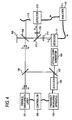
- FIG. 2 shows the configuration of a displacement measuring apparatus which is a first embodiment of the invention.
- the laser beam output from a variable wavelength (frequency) laser 101 is split by a beam splitter 106.
- One light beam is split by a beam splitter 108.
- One light beam is reflected by a reference mirror 109 configured by a planar mirror or the like, to be formed as a reference light beam.
- the other light beam irradiates an object 110 which is the measurement object of the distance (displacement), to obtain a light beam reflected therefrom as a measurement light beam.
- the measurement light beam is superimposed on the reference light beam by the beam splitter 108.
- a detector 111 receives signals of the reference and measurement light beams. On the basis of an interference intensity signal, the distance (displacement of the object 110) from the body of an interferometer to the object 110 is measured.
- the light beam reflected from the beam splitter 106 is superimposed on an optical comb generated from an optical comb generator 104 through a beam splitter 107, and then received by a detector 105.
- a frequency measuring apparatus 103 frequency-analyzes a beat signal of the optical comb generated from the optical comb generator 104 and the laser beam oscillated from the variable wavelength laser 101, and a controller 102 feedback controls the oscillation wavelength (frequency) of the variable wavelength laser 101.
- the optical comb is a laser beam in which lights of various wavelengths are arranged with equal intervals, like the teeth of a comb.
- f rep is a frequency spacing of the optical comb
- f cco is a fraction
- N is the order.
- the variable wavelength laser 101 oscillates at a predetermined wavelength ⁇ 1 , and the phase ⁇ 1 is calculated from an obtained interference signal.
- the wavelength ⁇ 1 can be obtained by accurately measuring the frequency (oscillation wavelength) of the variable wavelength laser 101 based on a beat frequency with respect to the optical comb generated the optical comb generator104, and controlling the variable wavelength laser 101 so as to attain the predetermined wavelength ⁇ 1 .
- Fig. 3A is a view schematically showing the spectrum of the optical comb and the laser beams of the predetermined wavelengths ⁇ 1 , ⁇ 2 .
- Fig. 3B schematically shows the manner of the frequency change of the beat signal when the wavelength is variable. In Fig.
- f rep is a frequency spacing of the optical comb
- n is a difference of orders between modes of the optical comb which the wavelengths ⁇ 1 , ⁇ 2 neighbor respectively
- ⁇ f 1 is a beat signal having the frequency of the difference between the laser beam of the wavelength ⁇ 1 , and the light of the optical comb adjacent to the laser beam of the wavelength ⁇ 1
- ⁇ f 2 is a beat signal having the frequency of the difference between the laser beam of the wavelength ⁇ 2 , and the light of the optical comb adjacent to the laser beam of the wavelength ⁇ 2 .
- variable wavelength laser 101 oscillates at a predetermined wavelength ⁇ 2 which is required for realizing a synthetic wavelength ⁇ S , and which is different from the wavelength ⁇ 1 . Then, an interference signal due to reflected light beams of the reference light beam and the measurement light beam is obtained, and an analysis value of the phase ⁇ 2 is obtained.
- the optical comb generator 104 can measure the frequency of light with an accuracy of 15 or more digits by using a cesium atomic clock as a reference. Therefore, the predetermined wavelengths ⁇ 1 , ⁇ 2 can be controlled with an accuracy of up to 15 digits. Consequently, the wavelength ⁇ S which is synthesized on the basis of the wavelengths ⁇ 1 , ⁇ 2 can be realized with a sufficiently high accuracy.
- the measurement procedure of the first embodiment is summarized as follows.
- Fig. 2 shows the method in which the oscillation wavelength of the one variable wavelength laser 101 is made variable to the wavelengths ⁇ 1 , ⁇ 2 and distances to the target are sequentially measured.
- a variable wavelength laser 201 which simultaneously outputs the laser beams of two or more wavelengths is used, and an optical system (a beam splitter 210, and bandpass filters 214, 215) in which an interference signal due to the predetermined wavelengths ⁇ 1 , ⁇ 2 are split and the split signals are simultaneously received and the detectors 111, 213 may be disposed.
- frequency (wavelength) measuring systems for the variable wavelength laser 201 and configured by the detector 105 and the frequency measuring apparatus 103 may be prepared respectively for the wavelengths ⁇ 1 , ⁇ 2 , or, as shown in Fig. 4 , one frequency measuring system may measure the both frequencies (wavelengths) ⁇ 1 , ⁇ 2 , and the laser may be controlled.
- Fig. 5 diagrammatically shows examples of the oscillation spectrum of the laser and an interference beat signal obtained in the case of the spectrum.
- an interference beat signal of the laser beams of the wavelengths ⁇ 1 , ⁇ 2 and the optical comb of the optical comb generator 104 is observed in a range of 1/2 of the frequency spacing f rep of the optical comb of the optical comb generator 104
- beat signals ⁇ f 1 , ⁇ f 2 , ⁇ f 12 the number of which is equal to that of combinations of the differences are observed as shown in (b 1 ) of Fig. 5 .
- beat signals ⁇ f 1 , ⁇ f 2 , ⁇ f 12 the number of which is equal to that of combinations of the differences are observed as shown in (b 1 ) of Fig. 5 .
- the laser beams of the wavelengths ⁇ 1 , ⁇ 2 interfere with different frequencies (orders) of the optical comb of the optical comb generator 144, the beat signals ⁇ f 1 , ⁇ f 2 of frequencies of the differences of the laser beams of the wavelengths ⁇ 1 , ⁇ 2 and respective neighboring lights of the optical comb are detected as shown in (b 2 ) of Fig. 5 .
- the frequencies of the beat signals are changed correspondingly with the wavelength change.
- one frequency measuring system can distinguish the wavelengths ⁇ 1 , ⁇ 2 from each other.
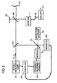
- the invention may be applied also to an interferometric measurement in the configuration such as a third embodiment shown in Fig. 6 .
- variable wavelength laser 101 is caused to oscillate at an arbitrary wavelength ⁇ 1 ' to measure the phase ⁇ 1 .
- the laser is caused to oscillate at an arbitrary wavelength ⁇ 2 ' which is different from the wavelength ⁇ 1 ', to measure the phase ⁇ 2 .
- the synthetic wavelength is substituted together with the synthetic phase ⁇ S obtained from the phases ⁇ 1 , ⁇ 2 in Expression (4), whereby the distance L to the object 110 can be calculated.
- the value of the synthetic wavelength ⁇ S varies depending on the values of the wavelengths ⁇ 1 ', ⁇ 2 '.
- the conversion to the length using the synthetic wavelength ⁇ S obtained from measured values is performed, and hence no influence is exerted on the measurement result.
- a special apparatus for controlling the wavelength of the variable wavelength laser 101 is not required, and a laser in which the current is variable and the frequency can be easily changed, such as a semiconductor laser can be used. Therefore, the measuring apparatus can be very simplified.
- a laser 416 which outputs the laser beam of the wavelength ⁇ 1 and a laser 417 which outputs the laser beam of the wavelength ⁇ 2 impinge on the interference optical system configured by the reference mirror 109 and the target 110, while being coaxially superimposed on each other.
- An interferometric measurement is performed by using the laser beams of the wavelengths ⁇ 1 , ⁇ 2 , the respective phases ⁇ 1 , ⁇ 2 are obtained, and the difference ⁇ S is calculated.
- the correct value of the wavelength ⁇ S in this case is correctly calculated by using ⁇ 1 and ⁇ 2 obtained by the frequency measuring system configured by the detector 105 and the frequency measuring apparatus 103.
- the distance L to the object 110 can be obtained from the obtained synthetic phase ⁇ S and synthetic wavelength ⁇ S .
- the wavelengths ⁇ 1 , ⁇ 2 at the instants when the phases ⁇ 1 , ⁇ 2 are respectively measured are obtained, even when the frequencies of the lasers 416, 417 are unstable, the unstable frequencies do not largely affect the measurement of the geometric distance L.
- the measurement resolution depends on the synthetic wavelength ⁇ S and the division number of the synthetic phase ⁇ S .
- ⁇ S 10 mm
- the division number of ⁇ S obtained from the difference between ⁇ 2 and ⁇ 1 500
- the measurement resolution is about 10 ⁇ m.
- the number of wavelengths used in the measurement is increased and kinds of synthetic wavelengths which can be produced by combinations are increased, a measurement which has a high resolution while ensuring a wide range can be easily realized.
- the wavelength of the variable wavelength laser 101 is switched to ⁇ 1 , ⁇ 2 , and ⁇ 3 , and the phase differences ⁇ 1 , ⁇ 2 and ⁇ 3 of the reference and measurement light beams are obtained at the respective wavelengths.
- the phase difference ⁇ i,j at the synthetic wavelength ⁇ Si,j which is produced by a combination of wavelengths, the position and displacement of the object 110 can be measured in a wide range and with a high resolution.
- the synthetic wavelength ⁇ S21 of the combination of ⁇ 1 and ⁇ 2 is 9,999 ⁇ m
- the synthetic wavelength ⁇ S31 of the combination of ⁇ 3 and ⁇ 1 is 49 ⁇ m.
- the division numbers of ⁇ S21 and ⁇ S31 derived on the basis of the respective synthetic wavelengths are equal to 500 in the same manner as the above-described example
- a measurement with a resolution of about 10 ⁇ m is enabled in the case of ⁇ S21
- that with a resolution of about 50 nm is enabled in the case of ⁇ S31 .
- a measurement result at a wavelength of one of ⁇ 1 , ⁇ 2 , and ⁇ 3 is used together, a measurement is enabled in a range of 10 mm with a resolution of 1 nm.
- the configuration can be easily realized in the case of, for example, Fig. 2 or 6 , by setting the number of the variable wavelengths to three.
- a laser which oscillates three wavelengths is used, and, in the case of Fig. 6 , three kinds of lasers are used, whereby the configuration can be easily realized.
- the configuration can be easily realized in a similar manner.
- the optical comb generator 104 which is described as an apparatus for measuring the frequency of a light beam can perform high resolution on each restricted frequency region in the spectral spacing of the comb.
- the frequencies in the optical comb 104 therefore, the light beam of the frequency with which interference is caused to produce the beat signal must be determined, or namely the order N must be separately determined.
- the order N may be determined in combination with means for measuring the wavelength, such as a wavemeter 601, the wavelengths ⁇ 1 , ⁇ 2 of the variable wavelength laser 101 may be measured, and the order may be used in the control of the oscillation frequency.
- a measurement may be performed by using ⁇ 2 in which a wavelength difference ⁇ is relatively formed with respect to the wavelength ⁇ 1 , and the distance L to the object 110 may be measured on the basis of the synthetic wavelength of ⁇ 1 and ⁇ 2 .
- an optical comb in which f CEO is correctly set is usually required, as described in " SANSOKEN TODAY Vol. 8 No. 1 MODE DOKI FIBER LASER O MOCHIITA KOTAIIKI OPTICAL COMB http://www.aist.go.jp/aisti_i/aistinfo/aist_today/vo108_01/p29.html ".
- an optical comb having a frequency band which is sufficiently broad for allowing f CEO to be determined is necessary.
- an optical comb which is to be used in the frequency measurement useful in the proposed lightwave interferometer may be a device having a minimum performance which covers the wavelength region to be used in the measurement. Consequently, the optical comb can be realized at a lower price.
- a planar mirror is used as the reference mirror 109.
- a retroreflector in which the optical axis alignment is easily performed, and the adjustment is facilitated may be used.
- a retroreflector may be attached to the surface of the object 110.
Landscapes
- Physics & Mathematics (AREA)
- General Physics & Mathematics (AREA)
- Engineering & Computer Science (AREA)
- Automation & Control Theory (AREA)
- Optics & Photonics (AREA)
- Instruments For Measurement Of Length By Optical Means (AREA)
- Length Measuring Devices By Optical Means (AREA)
Applications Claiming Priority (1)
| Application Number | Priority Date | Filing Date | Title |
|---|---|---|---|
| JP2008198185A JP5511162B2 (ja) | 2008-07-31 | 2008-07-31 | 多波長干渉変位測定方法及び装置 |
Publications (2)
| Publication Number | Publication Date |
|---|---|
| EP2149778A1 true EP2149778A1 (fr) | 2010-02-03 |
| EP2149778B1 EP2149778B1 (fr) | 2013-06-19 |
Family
ID=41259920
Family Applications (1)
| Application Number | Title | Priority Date | Filing Date |
|---|---|---|---|
| EP20090166890 Active EP2149778B1 (fr) | 2008-07-31 | 2009-07-30 | Procédé et appareil de mesure de déplacement interférométrique à plusieurs longueurs d'onde |
Country Status (2)
| Country | Link |
|---|---|
| EP (1) | EP2149778B1 (fr) |
| JP (1) | JP5511162B2 (fr) |
Cited By (3)
| Publication number | Priority date | Publication date | Assignee | Title |
|---|---|---|---|---|
| EP2555015A1 (fr) * | 2010-03-26 | 2013-02-06 | Hitachi, Ltd. | Dispositif et procédé pour mesurer une distance |
| EP2725385A1 (fr) * | 2011-06-23 | 2014-04-30 | Hitachi, Ltd. | Procédé et dispositif de mesure de distance |
| US9759550B2 (en) | 2012-07-19 | 2017-09-12 | Carl Zeiss Smt Gmbh | Projection exposure apparatus for microlithography comprising an optical distance measurement system |
Families Citing this family (4)
| Publication number | Priority date | Publication date | Assignee | Title |
|---|---|---|---|---|
| JP2012004426A (ja) * | 2010-06-18 | 2012-01-05 | Mitsutoyo Corp | 無変調安定化レーザ装置 |
| JP5654837B2 (ja) * | 2010-10-22 | 2015-01-14 | 株式会社ミツトヨ | 変位測定装置 |
| JP6052672B2 (ja) * | 2013-03-26 | 2016-12-27 | 株式会社ミツトヨ | 周波数測定装置、及び周波数測定方法 |
| WO2024132990A1 (fr) | 2022-12-20 | 2024-06-27 | Attocube Systems Ag | Système et procédé de mesure interférométrique de distance |
Citations (4)
| Publication number | Priority date | Publication date | Assignee | Title |
|---|---|---|---|---|
| JP2000146517A (ja) | 1998-11-17 | 2000-05-26 | Mitsutoyo Corp | 光波干渉計及び光波干渉計を用いた測長方法 |
| JP2004340690A (ja) | 2003-05-14 | 2004-12-02 | National Institute Of Advanced Industrial & Technology | 多色モードロックレーザを用いた光周波数測定装置及び測定方法 |
| EP1750086A1 (fr) * | 2005-08-01 | 2007-02-07 | Mitutoyo Corporation | Interféromètre de haute précision à double laser |
| JP2008051674A (ja) * | 2006-08-25 | 2008-03-06 | National Institute Of Advanced Industrial & Technology | 位置決め機構 |
Family Cites Families (4)
| Publication number | Priority date | Publication date | Assignee | Title |
|---|---|---|---|---|
| US5153669A (en) * | 1991-03-27 | 1992-10-06 | Hughes Danbury Optical Systems, Inc. | Three wavelength optical measurement apparatus and method |
| JPH04299203A (ja) * | 1991-03-28 | 1992-10-22 | Yokogawa Electric Corp | アブソリュ−ト測長器 |
| JP2007333428A (ja) * | 2006-06-12 | 2007-12-27 | Ricoh Co Ltd | 形状測定装置及び形状測定方法 |
| KR100951618B1 (ko) * | 2008-02-19 | 2010-04-09 | 한국과학기술원 | 광주파수 발생기를 이용한 절대거리 측정방법 및 시스템 |
-
2008
- 2008-07-31 JP JP2008198185A patent/JP5511162B2/ja not_active Expired - Fee Related
-
2009
- 2009-07-30 EP EP20090166890 patent/EP2149778B1/fr active Active
Patent Citations (4)
| Publication number | Priority date | Publication date | Assignee | Title |
|---|---|---|---|---|
| JP2000146517A (ja) | 1998-11-17 | 2000-05-26 | Mitsutoyo Corp | 光波干渉計及び光波干渉計を用いた測長方法 |
| JP2004340690A (ja) | 2003-05-14 | 2004-12-02 | National Institute Of Advanced Industrial & Technology | 多色モードロックレーザを用いた光周波数測定装置及び測定方法 |
| EP1750086A1 (fr) * | 2005-08-01 | 2007-02-07 | Mitutoyo Corporation | Interféromètre de haute précision à double laser |
| JP2008051674A (ja) * | 2006-08-25 | 2008-03-06 | National Institute Of Advanced Industrial & Technology | 位置決め機構 |
Non-Patent Citations (6)
| Title |
|---|
| KAJIMA ET AL.: "Super-heterodyne laser interferometer using femtosecond frequency comb for linear encoder calibration system", PROC. OF SPIE, vol. 6616, 2007 |
| M. KAJIMA, H. MATSUMOTO, SPIE, PO BOX 10 BELLINGHAM WA 98227-0010 USA, vol. 6616, 18 June 2007 (2007-06-18), pages 66160G-1 - 66160G-6, XP040242417 * |
| O. CIP, B. MIKEL, J. LAZAR, 26 April 2006, SPIE, PO BOX 10 BELLINGHAM WA 98227-0010 USA, XP040223400 * |
| SCHUHLER ET AL.: "Frequency-comb-referenced two wavelength source for absolute distance measurement", OPTICS LETTERS, vol. 31, no. 21, 1 November 2006 (2006-11-01), pages 3101 |
| SCHUHLER N ET AL: "Frequency-comb-referenced two-wavelength source for absolute distance measurement", OPTICS LETTERS OPT. SOC. AMERICA USA, vol. 31, no. 21, 1 November 2006 (2006-11-01), pages 3101 - 3103, XP002556913, ISSN: 0146-9592 * |
| TIP ET AL.: "Fast wavelength- scanning interferometry technique with derivative detection of quadrature signals", PROC OF SPIE, vol. 6188, 2006 |
Cited By (6)
| Publication number | Priority date | Publication date | Assignee | Title |
|---|---|---|---|---|
| EP2555015A1 (fr) * | 2010-03-26 | 2013-02-06 | Hitachi, Ltd. | Dispositif et procédé pour mesurer une distance |
| EP2555015A4 (fr) * | 2010-03-26 | 2014-12-17 | Hitachi Ltd | Dispositif et procédé pour mesurer une distance |
| US8982332B2 (en) | 2010-03-26 | 2015-03-17 | Hitachi, Ltd. | Distance measuring device and distance measuring method |
| EP2725385A1 (fr) * | 2011-06-23 | 2014-04-30 | Hitachi, Ltd. | Procédé et dispositif de mesure de distance |
| EP2725385A4 (fr) * | 2011-06-23 | 2015-04-01 | Hitachi Ltd | Procédé et dispositif de mesure de distance |
| US9759550B2 (en) | 2012-07-19 | 2017-09-12 | Carl Zeiss Smt Gmbh | Projection exposure apparatus for microlithography comprising an optical distance measurement system |
Also Published As
| Publication number | Publication date |
|---|---|
| EP2149778B1 (fr) | 2013-06-19 |
| JP5511162B2 (ja) | 2014-06-04 |
| JP2010038552A (ja) | 2010-02-18 |
Similar Documents
| Publication | Publication Date | Title |
|---|---|---|
| US8368900B2 (en) | Lightwave interferometric distance measuring method and apparatus using an optical comb | |
| EP2149778A1 (fr) | Procédé et appareil de mesure de déplacement interférométrique à plusieurs longueurs d'onde | |
| EP1794852B1 (fr) | Retroaction optique a partir d'un circuit d'accord a selection de mode | |
| JPH0749207A (ja) | 絶対干渉測定方法とこの方法に適したレーザー干渉装置 | |
| EP2606311B1 (fr) | Appareil et procédé pour mesurer une distance | |
| JP2002365142A (ja) | 波長測定装置、光学特性測定装置、波長測定方法及びフトウエア製品 | |
| WO2014203654A1 (fr) | Dispositif de mesure de distance, dispositif de mesure de forme, système de traitement, procédé de mesure de distance, procédé de mesure de forme, et procédé de traitement | |
| JPH07198320A (ja) | 絶対測定用の干渉測定方法およびこの方法に適したレーザー干渉計装置 | |
| JP6628030B2 (ja) | 距離測定装置及びその方法 | |
| US6462823B1 (en) | Wavelength meter adapted for averaging multiple measurements | |
| CN112082584B (zh) | 基于激光器调谐控制的光纤分布式物理量测量方法、装置及系统 | |
| US4611915A (en) | Absolute distance sensor | |
| US7768699B2 (en) | Laser phase difference detecting device and laser phase control device | |
| EP3548835B1 (fr) | Extension de la plage d'interférométrie à commande spectrale par superposition de multiples modulations spectrales | |
| JP2554363B2 (ja) | 光干渉測定装置 | |
| JPH01205486A (ja) | 半導体レ−ザの波長安定化装置 | |
| JP6895192B2 (ja) | 距離測定装置 | |
| JP2012184967A (ja) | 波長走査干渉計 | |
| JP3795257B2 (ja) | 測長装置および測長補正装置 | |
| JPH08101066A (ja) | 光スペクトラム測定装置 | |
| US11598628B1 (en) | High dynamic range picometer metrology systems and methods | |
| JP3149421B2 (ja) | リフレクトメータ | |
| JP2002131139A (ja) | 光ファイバセンサ並びに光ファイバの調節方法及び装置 | |
| JP2001280914A (ja) | 光干渉測定方法 | |
| JP2024115237A (ja) | 光路長差計測装置および振動計測装置 |
Legal Events
| Date | Code | Title | Description |
|---|---|---|---|
| PUAI | Public reference made under article 153(3) epc to a published international application that has entered the european phase |
Free format text: ORIGINAL CODE: 0009012 |
|
| AK | Designated contracting states |
Kind code of ref document: A1 Designated state(s): AT BE BG CH CY CZ DE DK EE ES FI FR GB GR HR HU IE IS IT LI LT LU LV MC MK MT NL NO PL PT RO SE SI SK SM TR |
|
| AX | Request for extension of the european patent |
Extension state: AL BA RS |
|
| 17P | Request for examination filed |
Effective date: 20100803 |
|
| 17Q | First examination report despatched |
Effective date: 20100830 |
|
| GRAP | Despatch of communication of intention to grant a patent |
Free format text: ORIGINAL CODE: EPIDOSNIGR1 |
|
| RAP1 | Party data changed (applicant data changed or rights of an application transferred) |
Owner name: MITUTOYO CORPORATION |
|
| GRAS | Grant fee paid |
Free format text: ORIGINAL CODE: EPIDOSNIGR3 |
|
| GRAA | (expected) grant |
Free format text: ORIGINAL CODE: 0009210 |
|
| AK | Designated contracting states |
Kind code of ref document: B1 Designated state(s): AT BE BG CH CY CZ DE DK EE ES FI FR GB GR HR HU IE IS IT LI LT LU LV MC MK MT NL NO PL PT RO SE SI SK SM TR |
|
| REG | Reference to a national code |
Ref country code: GB Ref legal event code: FG4D |
|
| REG | Reference to a national code |
Ref country code: CH Ref legal event code: EP |
|
| REG | Reference to a national code |
Ref country code: AT Ref legal event code: REF Ref document number: 617889 Country of ref document: AT Kind code of ref document: T Effective date: 20130715 |
|
| REG | Reference to a national code |
Ref country code: IE Ref legal event code: FG4D |
|
| REG | Reference to a national code |
Ref country code: DE Ref legal event code: R096 Ref document number: 602009016482 Country of ref document: DE Effective date: 20130814 |
|
| PG25 | Lapsed in a contracting state [announced via postgrant information from national office to epo] |
Ref country code: GR Free format text: LAPSE BECAUSE OF FAILURE TO SUBMIT A TRANSLATION OF THE DESCRIPTION OR TO PAY THE FEE WITHIN THE PRESCRIBED TIME-LIMIT Effective date: 20130920 Ref country code: FI Free format text: LAPSE BECAUSE OF FAILURE TO SUBMIT A TRANSLATION OF THE DESCRIPTION OR TO PAY THE FEE WITHIN THE PRESCRIBED TIME-LIMIT Effective date: 20130619 Ref country code: LT Free format text: LAPSE BECAUSE OF FAILURE TO SUBMIT A TRANSLATION OF THE DESCRIPTION OR TO PAY THE FEE WITHIN THE PRESCRIBED TIME-LIMIT Effective date: 20130619 Ref country code: ES Free format text: LAPSE BECAUSE OF FAILURE TO SUBMIT A TRANSLATION OF THE DESCRIPTION OR TO PAY THE FEE WITHIN THE PRESCRIBED TIME-LIMIT Effective date: 20130930 Ref country code: NO Free format text: LAPSE BECAUSE OF FAILURE TO SUBMIT A TRANSLATION OF THE DESCRIPTION OR TO PAY THE FEE WITHIN THE PRESCRIBED TIME-LIMIT Effective date: 20130919 Ref country code: SE Free format text: LAPSE BECAUSE OF FAILURE TO SUBMIT A TRANSLATION OF THE DESCRIPTION OR TO PAY THE FEE WITHIN THE PRESCRIBED TIME-LIMIT Effective date: 20130619 Ref country code: SI Free format text: LAPSE BECAUSE OF FAILURE TO SUBMIT A TRANSLATION OF THE DESCRIPTION OR TO PAY THE FEE WITHIN THE PRESCRIBED TIME-LIMIT Effective date: 20130619 |
|
| REG | Reference to a national code |
Ref country code: AT Ref legal event code: MK05 Ref document number: 617889 Country of ref document: AT Kind code of ref document: T Effective date: 20130619 |
|
| REG | Reference to a national code |
Ref country code: LT Ref legal event code: MG4D |
|
| PG25 | Lapsed in a contracting state [announced via postgrant information from national office to epo] |
Ref country code: HR Free format text: LAPSE BECAUSE OF FAILURE TO SUBMIT A TRANSLATION OF THE DESCRIPTION OR TO PAY THE FEE WITHIN THE PRESCRIBED TIME-LIMIT Effective date: 20130619 Ref country code: BG Free format text: LAPSE BECAUSE OF FAILURE TO SUBMIT A TRANSLATION OF THE DESCRIPTION OR TO PAY THE FEE WITHIN THE PRESCRIBED TIME-LIMIT Effective date: 20130919 |
|
| REG | Reference to a national code |
Ref country code: NL Ref legal event code: VDEP Effective date: 20130619 |
|
| PG25 | Lapsed in a contracting state [announced via postgrant information from national office to epo] |
Ref country code: LV Free format text: LAPSE BECAUSE OF FAILURE TO SUBMIT A TRANSLATION OF THE DESCRIPTION OR TO PAY THE FEE WITHIN THE PRESCRIBED TIME-LIMIT Effective date: 20130619 |
|
| PG25 | Lapsed in a contracting state [announced via postgrant information from national office to epo] |
Ref country code: AT Free format text: LAPSE BECAUSE OF FAILURE TO SUBMIT A TRANSLATION OF THE DESCRIPTION OR TO PAY THE FEE WITHIN THE PRESCRIBED TIME-LIMIT Effective date: 20130619 Ref country code: EE Free format text: LAPSE BECAUSE OF FAILURE TO SUBMIT A TRANSLATION OF THE DESCRIPTION OR TO PAY THE FEE WITHIN THE PRESCRIBED TIME-LIMIT Effective date: 20130619 Ref country code: PT Free format text: LAPSE BECAUSE OF FAILURE TO SUBMIT A TRANSLATION OF THE DESCRIPTION OR TO PAY THE FEE WITHIN THE PRESCRIBED TIME-LIMIT Effective date: 20131021 Ref country code: BE Free format text: LAPSE BECAUSE OF FAILURE TO SUBMIT A TRANSLATION OF THE DESCRIPTION OR TO PAY THE FEE WITHIN THE PRESCRIBED TIME-LIMIT Effective date: 20130619 Ref country code: IS Free format text: LAPSE BECAUSE OF FAILURE TO SUBMIT A TRANSLATION OF THE DESCRIPTION OR TO PAY THE FEE WITHIN THE PRESCRIBED TIME-LIMIT Effective date: 20131019 Ref country code: CY Free format text: LAPSE BECAUSE OF FAILURE TO SUBMIT A TRANSLATION OF THE DESCRIPTION OR TO PAY THE FEE WITHIN THE PRESCRIBED TIME-LIMIT Effective date: 20130821 Ref country code: SK Free format text: LAPSE BECAUSE OF FAILURE TO SUBMIT A TRANSLATION OF THE DESCRIPTION OR TO PAY THE FEE WITHIN THE PRESCRIBED TIME-LIMIT Effective date: 20130619 Ref country code: CZ Free format text: LAPSE BECAUSE OF FAILURE TO SUBMIT A TRANSLATION OF THE DESCRIPTION OR TO PAY THE FEE WITHIN THE PRESCRIBED TIME-LIMIT Effective date: 20130619 |
|
| PG25 | Lapsed in a contracting state [announced via postgrant information from national office to epo] |
Ref country code: NL Free format text: LAPSE BECAUSE OF FAILURE TO SUBMIT A TRANSLATION OF THE DESCRIPTION OR TO PAY THE FEE WITHIN THE PRESCRIBED TIME-LIMIT Effective date: 20130619 Ref country code: RO Free format text: LAPSE BECAUSE OF FAILURE TO SUBMIT A TRANSLATION OF THE DESCRIPTION OR TO PAY THE FEE WITHIN THE PRESCRIBED TIME-LIMIT Effective date: 20130619 Ref country code: PL Free format text: LAPSE BECAUSE OF FAILURE TO SUBMIT A TRANSLATION OF THE DESCRIPTION OR TO PAY THE FEE WITHIN THE PRESCRIBED TIME-LIMIT Effective date: 20130619 |
|
| REG | Reference to a national code |
Ref country code: CH Ref legal event code: PL |
|
| PG25 | Lapsed in a contracting state [announced via postgrant information from national office to epo] |
Ref country code: CY Free format text: LAPSE BECAUSE OF FAILURE TO SUBMIT A TRANSLATION OF THE DESCRIPTION OR TO PAY THE FEE WITHIN THE PRESCRIBED TIME-LIMIT Effective date: 20130619 Ref country code: MC Free format text: LAPSE BECAUSE OF FAILURE TO SUBMIT A TRANSLATION OF THE DESCRIPTION OR TO PAY THE FEE WITHIN THE PRESCRIBED TIME-LIMIT Effective date: 20130619 |
|
| REG | Reference to a national code |
Ref country code: IE Ref legal event code: MM4A |
|
| PLBE | No opposition filed within time limit |
Free format text: ORIGINAL CODE: 0009261 |
|
| STAA | Information on the status of an ep patent application or granted ep patent |
Free format text: STATUS: NO OPPOSITION FILED WITHIN TIME LIMIT |
|
| PG25 | Lapsed in a contracting state [announced via postgrant information from national office to epo] |
Ref country code: LI Free format text: LAPSE BECAUSE OF NON-PAYMENT OF DUE FEES Effective date: 20130731 Ref country code: DK Free format text: LAPSE BECAUSE OF FAILURE TO SUBMIT A TRANSLATION OF THE DESCRIPTION OR TO PAY THE FEE WITHIN THE PRESCRIBED TIME-LIMIT Effective date: 20130619 Ref country code: CH Free format text: LAPSE BECAUSE OF NON-PAYMENT OF DUE FEES Effective date: 20130731 |
|
| 26N | No opposition filed |
Effective date: 20140320 |
|
| PG25 | Lapsed in a contracting state [announced via postgrant information from national office to epo] |
Ref country code: IT Free format text: LAPSE BECAUSE OF FAILURE TO SUBMIT A TRANSLATION OF THE DESCRIPTION OR TO PAY THE FEE WITHIN THE PRESCRIBED TIME-LIMIT Effective date: 20130619 |
|
| REG | Reference to a national code |
Ref country code: DE Ref legal event code: R097 Ref document number: 602009016482 Country of ref document: DE Effective date: 20140320 |
|
| PG25 | Lapsed in a contracting state [announced via postgrant information from national office to epo] |
Ref country code: IE Free format text: LAPSE BECAUSE OF NON-PAYMENT OF DUE FEES Effective date: 20130730 |
|
| PG25 | Lapsed in a contracting state [announced via postgrant information from national office to epo] |
Ref country code: SM Free format text: LAPSE BECAUSE OF FAILURE TO SUBMIT A TRANSLATION OF THE DESCRIPTION OR TO PAY THE FEE WITHIN THE PRESCRIBED TIME-LIMIT Effective date: 20130619 |
|
| PG25 | Lapsed in a contracting state [announced via postgrant information from national office to epo] |
Ref country code: MT Free format text: LAPSE BECAUSE OF FAILURE TO SUBMIT A TRANSLATION OF THE DESCRIPTION OR TO PAY THE FEE WITHIN THE PRESCRIBED TIME-LIMIT Effective date: 20130619 Ref country code: TR Free format text: LAPSE BECAUSE OF FAILURE TO SUBMIT A TRANSLATION OF THE DESCRIPTION OR TO PAY THE FEE WITHIN THE PRESCRIBED TIME-LIMIT Effective date: 20130619 |
|
| PG25 | Lapsed in a contracting state [announced via postgrant information from national office to epo] |
Ref country code: LU Free format text: LAPSE BECAUSE OF NON-PAYMENT OF DUE FEES Effective date: 20130730 Ref country code: HU Free format text: LAPSE BECAUSE OF FAILURE TO SUBMIT A TRANSLATION OF THE DESCRIPTION OR TO PAY THE FEE WITHIN THE PRESCRIBED TIME-LIMIT; INVALID AB INITIO Effective date: 20090730 Ref country code: MK Free format text: LAPSE BECAUSE OF FAILURE TO SUBMIT A TRANSLATION OF THE DESCRIPTION OR TO PAY THE FEE WITHIN THE PRESCRIBED TIME-LIMIT Effective date: 20130619 |
|
| REG | Reference to a national code |
Ref country code: FR Ref legal event code: PLFP Year of fee payment: 8 |
|
| REG | Reference to a national code |
Ref country code: FR Ref legal event code: PLFP Year of fee payment: 9 |
|
| REG | Reference to a national code |
Ref country code: FR Ref legal event code: PLFP Year of fee payment: 10 |
|
| PGFP | Annual fee paid to national office [announced via postgrant information from national office to epo] |
Ref country code: GB Payment date: 20230720 Year of fee payment: 15 |
|
| PGFP | Annual fee paid to national office [announced via postgrant information from national office to epo] |
Ref country code: FR Payment date: 20230725 Year of fee payment: 15 |
|
| PGFP | Annual fee paid to national office [announced via postgrant information from national office to epo] |
Ref country code: DE Payment date: 20240719 Year of fee payment: 16 |