EP2148136B1 - Kamin mit einem Abgasschacht - Google Patents
Kamin mit einem Abgasschacht Download PDFInfo
- Publication number
- EP2148136B1 EP2148136B1 EP09009598A EP09009598A EP2148136B1 EP 2148136 B1 EP2148136 B1 EP 2148136B1 EP 09009598 A EP09009598 A EP 09009598A EP 09009598 A EP09009598 A EP 09009598A EP 2148136 B1 EP2148136 B1 EP 2148136B1
- Authority
- EP
- European Patent Office
- Prior art keywords
- cover
- shaft wall
- nozzle
- connecting piece
- chimney
- Prior art date
- Legal status (The legal status is an assumption and is not a legal conclusion. Google has not performed a legal analysis and makes no representation as to the accuracy of the status listed.)
- Active
Links
Images


Classifications
-
- F—MECHANICAL ENGINEERING; LIGHTING; HEATING; WEAPONS; BLASTING
- F23—COMBUSTION APPARATUS; COMBUSTION PROCESSES
- F23J—REMOVAL OR TREATMENT OF COMBUSTION PRODUCTS OR COMBUSTION RESIDUES; FLUES
- F23J13/00—Fittings for chimneys or flues
- F23J13/08—Doors or covers specially adapted for smoke-boxes, flues, or chimneys
Definitions
- the invention relates to a fireplace according to the preamble of claim 1.
- a fireplace is made, for example DE 10 2006 050 401 A1 known.
- a lateral shaft wall opening is provided through which access to the exhaust duct is made possible, e.g. for cleaning, revision or maintenance of the exhaust shaft.
- a socket in the region of the shaft wall opening, which is provided with a resealable door.
- Such sockets may be formed either integrally with the ceramic exhaust pipe, e.g. by isostatic pressing, or only after the burning of the exhaust pipe, by cutting the lateral shaft wall opening and so-called Angamieren of suitable ceramic supplementary fittings to the exhaust pipe by means of a cement or adhesive.
- the resealable door for closing the nozzle is also called a cleaning or inspection door.
- sealing rings made of plastic are generally required, which seal the gap between the inspection door and the nozzle.
- Such a closure system can be designed, for example, as a two-shell metal door with a circumferential elastomeric seal arranged between the shells. By tightening a screw, the two shells are moved toward each other, which leads to a bulge of the elastomeric seal to the outside, ie against the inside of the tubular nozzle. Due to the low temperature resistance of the sealing materials (plastics) used, these closure systems are not resistant to soot fire and can only be used at lower exhaust gas temperatures, eg in the range of 200 ° C (eg temperature class T200 according to EN 1443).
- the invention is therefore based on the object to provide a fireplace that is resistant to soot fire and meets higher requirements for gas tightness.
- the closure device is at least three parts. It comprises an inner lid, an insulating element and an outer lid.
- the inner lid forms the conclusion of the closure device to the hot exhaust duct and can be designed so that it virtually replaces the shaft wall in the shaft wall opening there.
- the inner wall of the inner lid, which faces toward the shaft wall, is designed such that it forms an end surface aligned with the shaft wall.
- the insulating element serves primarily for thermal insulation, but may also have other functions, e.g. Sound insulation and, to some extent, sealing.
- the outer lid closes the neck to the outside and may contain sealing elements. Preferably results from this external arrangement of the outer lid and the upstream insulating element that the outer lid has a relatively low temperature load.
- the outer cover is thus particularly suitable for sealing by means of intermediate insulation elements.
- the chimney is a chimney device as an exhaust system for connecting fireplaces, e.g. Furnaces for various fuels.
- the exhaust shaft which is to be connected to the fireplaces for the withdrawal of the exhaust gas, may be formed as a pipe, preferably socket pipe, or as a masonry shaft.
- the chimney can be single-shelled or multi-shelled.
- the chimney is designed only as an exhaust shaft, limited by the shaft wall.
- the shaft wall is formed by the pipe wall or the masonry shaft wall.
- the neck of the closure device opens with its inner end directly into the Exhaust shaft and protrudes with its outer end of the exhaust shaft to the outside.
- the chimney is formed Kischalig, it comprises an outer shell and an inner shell, wherein the inner shell forms the exhaust shaft in its interior
- the outer shell forms an outer chimney shaft, in which the inner shell is arranged with the exhaust shaft.
- the closure device provides that the nozzle ends with its outer end in the outer chimney shaft or passes through the outer shell and opens with its inner end in the region of the shaft wall opening in the inner shell.
- the nozzle can be made longer than single-shell chimneys. Therefore, more space is available for the components of the closure device arranged in the neck.
- the outer shell in an area in which an extension of the nozzle beyond the outer end of the connecting piece along its longitudinal axis meets the outer shell, one with a coat stone closure having closable passage opening.
- the chimney can be formed with three shells, wherein it comprises an outer shell, an inner shell and an insulating shell arranged between the outer shell and the inner shell, and wherein the inner shell forms the exhaust gas shaft in its interior.
- the insulating shell is used for thermal insulation of the exhaust shaft, eg to prevent or reduce condensates.
- the insulating shell is arranged in the cavity formed between the outer shell and the inner shell.
- the insulating shell is arranged directly on the inner shell. Between the outside of the insulating shell and the inside of the outer shell, a free space is formed, which can serve as a supply air duct.
- the engaging in the shaft wall opening portion of the inner lid has a front end, which is formed flush with the inside of the shaft wall. Due to the positive connection of the inner lid to the shaft wall no projection or recess is present, where the heat flow of the hot exhaust gas flowing in the exhaust duct can catch. This prevents the components in the nozzle from overheating and thus being damaged.
- the nozzle is arranged eccentrically to the shaft wall opening outside of the shaft wall in the region of the shaft wall opening.
- the nozzle is arranged eccentrically so far upwards shifted with respect to the shaft wall opening on the outside of the shaft wall, so that the nozzle is not congruent centric in the connection area, with which he is placed on the shaft wall Shaft wall opening is arranged, but offset to this. This avoids an undercut in the lower region of the connection point, so that condensate occurring in the connection piece can not collect there but flows off into the exhaust gas shaft.
- the eccentric arrangement may be formed so that the shaft wall protrudes into the opening cross section of the nozzle at the upper vertex of the nozzle and thus forms a stop for the inner lid.
- the stop can thus be used to securely hold the engaging in the shaft wall opening portion of the inner lid in the shaft wall opening. This prevents the inner cover from falling into the exhaust duct.
- the closure device has a holding device, by which the inner lid is held in a predetermined position. It is possible for the holding device to have a stop and a counterstop that can be brought into contact with the stop, the stop being arranged on the inner lid and the counterstop being arranged on the shaft wall and / or on the connecting piece. It is possible that the holding device has a stop and a counter-stop cooperating with the stop. The stop is arranged on the inner cover and comes in the correct position of the inner lid on the arranged on the shaft wall and / or on the nozzle counter-stop to the plant. It is particularly preferred if the holding device is designed as a projection arranged on the outer circumference of the inner lid, which comes into contact with the outside of the shaft wall. Preferably, the projection is arranged in a partial region, preferably an upper section, of the inner lid.
- the nozzle is arranged on the outside of the shaft wall, that condensate occurring in the nozzle can flow into the exhaust shaft. It is possible that the longitudinal axis of the nozzle is inclined to the exhaust duct. As a result, liquid flows by itself from the nozzle into the exhaust shaft.
- the inner lid is at least partially formed of a ceramic material.
- the production of the inner lid can be done in a casting or die casting for components in the fireplace.
- the inner lid has a sealing element which has a circumferential gap between the inner lid and the inside of the nozzle, i. the inner wall of the nozzle, seals.
- the sealing element is designed as a sealing cord or a sealing tape.
- the sealing element of the inner lid is arranged in a circumferential groove of the arranged inside the nozzle portion of the inner lid.
- the outer lid has a lid, consisting of a ceramic material and / or metal, and at least one sealing element.
- the at least one sealing element is designed such that it seals a circumferential gap between the outer cover and the inside of the connecting piece.
- the outer cover comprises a two against each other sliding shells having metal lid.
- the at least one sealing element is preferably formed as a arranged between the two shells Deckelstauchdichtung.
- the outer cover has a ceramic cover
- the at least one sealing element comprises a sealing collar, which is arranged on the outside of the nozzle and that of the exhaust gas shaft opposite side of the ceramic cover at least partially, preferably annular along the outer circumference of the nozzle, covered.
- the sealing collar is made of an elastomer.
- the outer lid has a clamping band which presses the sealing collar against the outside of the nozzle.
- the at least one sealing element of the outer cover comprises a sealing cord or a sealing strip which is arranged in a circumferential groove of the section of the outer cover arranged inside the connecting piece.
- the insulating element is formed of a heat-insulating material.
- the insulating element has an insulating mat made of fibrous insulating materials.
- the insulating element is designed as an insulating board with a arranged on the side facing away from the exhaust duct side of the insulating board grip band.
- the closure device is tight up to an overpressure of 200 Pa in the exhaust shaft relative to the ambient pressure of the chimney.
- the closure device is soot fire resistant.
- the closure device has a maximum leakage rate of 0.006 l / (sm 2 ).
- the inner lid is produced by a casting process.
- the shaft wall opening has a round circumference or cross section.
- the nozzle has a round cross-section.
- the inner lid and / or the outer lid and / or the insulating element has a round Have or have cross-section. It is advantageous if the diameter of the insulating element is just as large or slightly larger than the inner diameter of the nozzle. As a result, the insulating element is firmly against the inside of the nozzle. In this way, a good thermal seal can be achieved even in the edge regions of the Dämmelements.
- the outer lid is designed as a rotary closure.
- the outer cover can be screwed into position in the nozzle.
- the outer lid can be rotated out of its position in the nozzle.
- the outer cover is designed as a rotary closure, the nozzle and the outer cover on a round cross-section.
- the inner lid is designed as a plug-in part.
- the inner lid is inserted without rotational movement in the nozzle and brought by a plug movement in its predetermined position.
- To remove the inner lid of the inner lid is released by train from its position and led out of the socket.
- FIG. 1a shows a horizontal section through the chimney 4.
- an exhaust pipe is arranged, which is designed as Schamotterohr 21.
- the vertical longitudinal center axis of the Schamotterohrs 21 coincides with the vertical longitudinal center axis of the formed in the lightweight concrete shell 41 chimney shaft 43.
- the interior of the Schamotterohrs 21 forms a flue shaft 2 for the withdrawal of flue gas from a fireplace into the open.
- the inner wall 21i of the shaft wall 21 forms the boundary surface of the exhaust shaft 2.
- the vertical longitudinal central axis of the Schamotterohrs coincides with the vertical longitudinal central axis 23 of the exhaust shaft 2.
- the shaft wall 21 has a circular shaft wall opening 22, which passes through the shaft wall 21.
- a tubular connecting piece 3 is arranged, which opens in the region of the shaft wall opening 22.
- the nozzle 3 may be integrally formed on the outer side 21 a of the shaft wall 21 or attached later to the outside of the shaft wall 21, z. B. by a ceramic adhesive bond.
- the nozzle 3 protrudes outward, that is from the Schamotterohr 21 in the direction of the lightweight concrete jacket 41.
- the outwardly projecting front end of the nozzle 3 ends in the illustrated embodiment within the flue 43.
- the lightweight concrete shell 41 has formed therein Through opening, which is closed with a mantle closure 42.
- Usual pipe diameter of the nozzle 3 are in a range of 80 mm to 250 mm.
- a remaining between the Schamotterohr 21 and the lightweight concrete shell 41 cavity of the flue shaft 43 can be used as a supply air duct. Additionally or alternatively, a thermal insulation layer for thermal insulation of the exhaust shaft 2 can be arranged in the cavity.
- the nozzle 3 communicates with the shaft wall opening 22.
- the nozzle 3 with the closure device 1 is accessible from the outside. This is necessary for the maintenance and cleaning of the exhaust shaft 2.
- the closure device 1 is arranged, through which the connecting channel is sealed gas-tight. For reasons of clarity, the closure device 1 is in Fig. 1a not shown.
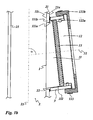
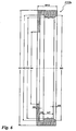
- Fig. 1b shows a vertical section of a first embodiment of the fireplace 4 in the region of the nozzle 3.
- the in Fig. 1b Closure device 1 shown has an outer lid 12, which comprises a lid, consisting of a ceramic material. For reasons the clarity is the lightweight concrete shell 41 in Fig. 1b not shown.
- the nozzle 3 is shown enlarged relative to the exhaust duct 2.
- the Schamotterohrs 21 extends, as already mentioned above, the vertical exhaust shaft 2.
- the Schamotterohr 21, ie the shaft wall 21 of the exhaust shaft 2 is broken through the shaft wall opening 22.
- the nozzle 3 is arranged on the outer side 21 a of the Schamotterohrs 21 and opens with its inner end in the region of the shaft wall opening 22.
- the facing away from the exhaust shaft 2 front end of the nozzle 3, ie the outwardly projecting front end forms an outer end face of the nozzle. 3 ,
- the nozzle 3 opens at an acute angle in the Schamotterohr 21 so that liquid, which is located in the nozzle 3, flows by gravity into the Schamotterohr 21.
- the longitudinal axis 31 of the nozzle 3 with the longitudinal central axis 23 of the exhaust shaft 2 includes an acute angle ⁇ of about 80 degrees.
- the closure device 1 comprises an inner lid 11 made of ceramic material, which is arranged in the shaft wall opening 22 and arranged with a portion inside the nozzle 3.
- the closure device 1 further comprises an outer cover 12 made of ceramic material, which is arranged with an inner portion within the nozzle 3 and with an outer portion on the outer end side of the nozzle 3.
- the closure device 1 comprises an insulating element 13 made of a fiber insulating material, which is disposed within the nozzle 3 between the inner lid 11 and the outer lid 12.
- the engaging in the shaft wall opening 22 portion of the inner lid 11 has an end face that matches the curvature of the Inner side 21i of the shaft wall 21 is curved and in the closed position is aligned in the inner side 21i of the shaft wall 21 is formed.
- the clear diameter of the nozzle 3 corresponds to the clear diameter of the shaft wall opening 22.
- the cross section of the nozzle perpendicular to its longitudinal central axis is circular. Also circular is the cross section of the exhaust shaft 2.
- the nozzle 3 is not arranged congruent to the shaft wall opening 22, but eccentric to this. As a result, covers the shaft wall 21 at the upper vertex of the nozzle 3 from a portion of the nozzle cross-section, forming a stop for the inner lid 11.
- the nozzle 3 is offset from the shaft wall 21 upwards. This avoids an undercut in which any condensate that might accumulate is avoided.
- the inner lid 11 has along its edge a circumferential groove into which a sealing cord 112 is inserted.
- the sealing cord seals a circumferential gap between the inner lid 11 and the inside of the nozzle 3.
- the diameter of the sealing cord is e.g. 4 mm.
- the outer lid 12 includes a lid made of a ceramic material and two sealing members 122a, 122b.
- the lid has a portion which is disposed within the nozzle 3, and a portion which is outside the nozzle 3, namely on the outer end side of the nozzle 3, is arranged.
- the outer cover 12 has at the disposed within the nozzle 3 portion along its edge a circumferential groove into which a sealing cord 122a is inserted.
- the sealing cord seals a circumferential gap between the outer cover 12 and the inside of the nozzle 3.
- the diameter of the sealing cord is for example 12 mm.
- the outer cover 12 also has a sealing collar 122b, which is arranged in the region of the outer end side of the connecting piece 3 around the outer circumference of the connecting piece 3 and covers the side of the cover facing away from the exhaust shaft 2 annularly.
- This sealing collar 122b is pressed by a clamping band 123 against the outer circumference of the nozzle 3 and thereby held.,
- the sealing collar 122b also seals the circumferential gap between the outer lid 12 and the inside of the nozzle 3 from.
- the insulating element 13 is located inside the nozzle 3 between the inner lid 11 and the outer lid 12.
- the insulating element is made of a heat-insulating, heat-resistant material, e.g. an insulation mat made of soft, elastic fibrous insulation materials (glass or ceramic fibers) or of harder insulating materials (stone or glass wool).
- insulating element 13 is an insulating plate or - disc with a circular circumference.
- the diameter of the Dämmelements 13 is up to about 5 mm larger than the inner diameter of the nozzle 3. That is, assuming an inner diameter of the nozzle 3 of 180 mm, the diameter of the Dämmelements 13 is in a range between 180 and 185 mm.
- the thickness of the Dämmelements can be up to 50 mm, preferably it is in a range of 30 mm.
- the insulating element 13 In order to use the insulating element 13 in its position within the nozzle 2 and to be able to remove it from its position again, the insulating element 13 has a grip band, which is firmly connected to the insulating element.
- the grip band is also made of a heat-resistant material.
- the grip band may extend over the entire diameter of the Dämmelements 13 or be formed as a loop on the Dämmusion.
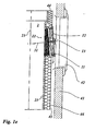
- Fig. 1c shows a vertical section of a second embodiment of the fireplace 4 in the region of the nozzle 3.
- the in Fig. 1c The closure device 1 shown has an outer cover 12 which comprises a cover consisting of metal.
- the vertical section shows the exhaust gas shaft 2 with its longitudinal central axis 23.
- the shaft wall 21 of the exhaust shaft 2 is the shaft wall opening 22.
- the closure device 1 is arranged in which the shaft wall opening 22 surrounding nozzle 3 with the longitudinal central axis 31, the closure device 1 is arranged.
- the closure device 1 comprises an inner lid 11 made of a ceramic material, an outer lid 12 made of metal and an insulating element 13 between the inner lid 11 and the outer lid 12.
- Fig. 1c shows that the outwardly projecting front end of the nozzle 3 ends within the flue 43.
- the through hole formed therein which is closed with the mantle closure 42.
- Fig. 1d shows a horizontal section through a three-shell embodiment of the chimney 4, which on the in Fig. 1a based bivalve embodiment is based.
- three-shell embodiment has an arranged inside the chimney flue 43 insulating shell 44, which is arranged adjacent to the shaft wall 21 and the shaft wall 21 surrounds.
- the chimney 4 therefore has an inner shell 21, an insulating shell 44 and an outer shell 41. Between the outside of the insulating shell 44 and the inside of the outer shell 41 remains in the chimney 43 a free space that can serve as a supply air duct.
- the insulating shell 44 may be made of a heat-insulating, heat-resistant material, such as an insulating mat made of soft, elastic fibrous insulating materials (glass or ceramic fibers) or harder insulating materials (stone or glass wool).
- Fig. 1e shows a vertical section through a three-shell embodiment of the chimney 4, which on the in Fig. 1c based bivalve embodiment is based.
- three-shell embodiment has an arranged inside the chimney flue 43 insulating shell 44, which is arranged adjacent to the shaft wall 21 and the shaft wall 21 surrounds.
- the insulating shell 44 rests at least in a partial area on the outer circumference of the nozzle 3.
- the nozzle 3 passes through the insulating shell 44 such that the cover 12 is accessible via the jacket stone closure, ie when the jacket stone closure 42 is lifted out.
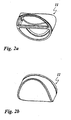
- Fig. 2a shows a perspective view of the side facing away from the exhaust duct 2 side of the inner lid 11.
- the lid is made of a ceramic material. It is designed as an open hollow body and has a horizontally extending handle bar on which the inner lid 11 can be used for insertion into and removal from its position.
- the narrow web on the upper edge of the lid 11 has the projection which comes to rest on the outer side 21 a of the shaft wall 21.
- the outer lid 12 is designed as a plug-in element.
- Fig. 2b shows a perspective view of the exhaust duct 2 facing side of the inner lid 11.
- This page has a curvature, which corresponds to the course of the shaft wall 21 in the region of the shaft wall opening 22.
- Fig. 2c shows a plan view of the side facing away from the exhaust duct 2 side of the inner lid eleventh
- Fig. 2d shows a section of the inner lid 11 along in Fig. 2c specified section line AA.
- Fig. 2e shows a plan view of the edge of the inner lid eleventh
- Table 1 are for in the FIGS. 2a to 2e shown inner lid 11 possible component dimensions, corresponding to the reference numerals ID1, ID2, ID3, ID4, ID5, ⁇ , R1, R2 listed. These dimensions represent preferred dimensions.
- Table 1 ID1 ID2 ID3 ID4 ID5 ⁇ R1 R3 77 mm 11 mm 170 mm 8 mm 177 mm 5.8 ° 98.5 mm 90.5 mm
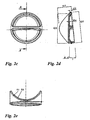
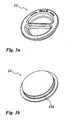
- Fig. 3a shows a perspective view of the side facing away from the exhaust duct 2 side of the outer lid 12.
- the lid is made of a ceramic material. It is designed as an open hollow body and has a horizontally extending handle bar on which the outer cover 12 can be used for insertion into and removal from its position.
- the outer lid 12 is designed as a rotary closure.
- Fig. 3b shows a perspective view of the exhaust gas shaft 2 facing side of the outer lid 12.
- This page has a flat surface on which the insulating element 13 comes to rest.
- the outer cover 12 has an outer edge, which comes to rest on the outer end side of the nozzle.
- the outer cover 12 has at the portion disposed within the nozzle 3 an edge along which a circumferential groove 124 is arranged. In this groove 124 a sealing cord is arranged.
- Fig. 3c shows a plan view of the side facing away from the exhaust duct 2 side of the outer lid 12th
- Fig. 3d shows a section of the outer lid 12 along in FIG Fig. 3c specified section line AA.
- Fig. 3e shows a plan view of the edge of the outer lid 12th
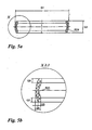
- Fig. 4a shows a section of an outer cover 12 made of metal along the axis of symmetry of the outer lid 12.
- the outer cover 12 has two corresponding in shape to each other metal shells with circular outer circumference, which can be moved by means of a screw along the axis of symmetry toward or away from each other ,
- each of the metal shells has an angle profile, which together form a circumferential groove.
- an annular Deckelauchauchdichtung is arranged, whose edges are arranged in each one of the angle sections.
- the Deckelauchauchdichtung has a small outwardly facing bulge, in whose vertex a knob is arranged.
- the lid compression seal is made of silicone, for example.
- the metal lid 12 is inserted into the neck 3, that the outer periphery of the outer metal shell rests against the outer end side of the nozzle 3 and the Deckelstauchdichtung the inside of the nozzle 3 is opposite. Now, if the metal shells shifted toward each other, the lid compression seal, the already preformed bulge following, bulges outward and seals the gap between the outer lid and the inside of the nozzle 3.
- Fig. 4b shows the in Fig. 4a specified section Y in an enlarged view.
- Table 3 are for in the FIGS. 4a and 4b shown outer cover 12 possible component dimensions for seven different sizes, corresponding to the reference numerals P1 to P8, R4 listed. These dimensions are preferred dimensions. Dimensions are in millimeters. Table 3 nominal width P1 P2 P3 P4 P5 P6 P7 P8 R4 80 100 24 50 69 76 22 1 4 1 100 120 24 60 89 96 22 1 4 1 120 140 30 70 109 116 22 1 4 1 140 160 30 70 129 136 22 1 4 1 160 180 30 70 149 156 22 1 4 1 180 200 30 105 169 176 22 1 4 1 200 220 30 105 189 196 22 1 4 1
- Fig. 5a shows a section of an alternative annular Deckelauchauchdichtung.
- the lid compression seal is made of a fluororubber, eg Viton ® .
- Fig. 5b shows the in Fig. 5a specified section X in an enlarged view.
- Fig. 6 shows a section of a sealing collar 122b.
- the sealing collar has an outer portion, which covers the outwardly, ie the side facing away from the exhaust duct 21 side of the outer lid 12 annular.
- the sealing collar has an inner portion which is disposed over the outside of the nozzle 3.
- the sealing collar In order to prevent accidental slipping of the sealing sleeve from the outside of the neck 3, the sealing collar on the inside of the inner portion on two circumferential beads.
- a clamping band can be arranged on the outer circumference of the sealing sleeve. By tightening the clamping band, the sealing sleeve is pressed gas-tight against the outside of the nozzle 3.
Landscapes
- Engineering & Computer Science (AREA)
- Mechanical Engineering (AREA)
- General Engineering & Computer Science (AREA)
- Thermal Insulation (AREA)
- Incineration Of Waste (AREA)
- Chimneys And Flues (AREA)
- Separation Of Particles Using Liquids (AREA)
- Exhaust Silencers (AREA)
- Gasket Seals (AREA)
Priority Applications (2)
| Application Number | Priority Date | Filing Date | Title |
|---|---|---|---|
| SI200930142T SI2148136T1 (sl) | 2008-07-26 | 2009-07-24 | Dimnik z jaškom dimnih plinov |
| PL09009598T PL2148136T3 (pl) | 2008-07-26 | 2009-07-24 | Komin z szybem gazów odlotowych |
Applications Claiming Priority (1)
| Application Number | Priority Date | Filing Date | Title |
|---|---|---|---|
| DE102008034925.9A DE102008034925B4 (de) | 2008-07-26 | 2008-07-26 | Kamin mit einem Abgasschacht |
Publications (2)
| Publication Number | Publication Date |
|---|---|
| EP2148136A1 EP2148136A1 (de) | 2010-01-27 |
| EP2148136B1 true EP2148136B1 (de) | 2011-10-12 |
Family
ID=41210645
Family Applications (1)
| Application Number | Title | Priority Date | Filing Date |
|---|---|---|---|
| EP09009598A Active EP2148136B1 (de) | 2008-07-26 | 2009-07-24 | Kamin mit einem Abgasschacht |
Country Status (7)
| Country | Link |
|---|---|
| EP (1) | EP2148136B1 (pl) |
| AT (1) | ATE528587T1 (pl) |
| DE (1) | DE102008034925B4 (pl) |
| DK (1) | DK2148136T3 (pl) |
| HR (1) | HRP20110979T1 (pl) |
| PL (1) | PL2148136T3 (pl) |
| SI (1) | SI2148136T1 (pl) |
Families Citing this family (1)
| Publication number | Priority date | Publication date | Assignee | Title |
|---|---|---|---|---|
| EP4555626A4 (en) * | 2023-03-22 | 2025-10-01 | Cnbm Res Institute For Advanced Glass Materials Group Co Ltd | NEW VENTILATION STRUCTURE FOR BIPV MODULES |
Family Cites Families (7)
| Publication number | Priority date | Publication date | Assignee | Title |
|---|---|---|---|---|
| DE909763C (de) * | 1941-10-21 | 1954-04-26 | Joseph Schwend | Reinigungstuer fuer Schornsteine |
| DE2212193A1 (de) * | 1972-03-14 | 1973-09-20 | Alois Rawitzer | Anschlussformstueck fuer reinigungsund kontrolltueren fuer kamine |
| DE7701316U1 (de) * | 1977-01-18 | 1977-04-28 | Guwa Vertriebsgesellschaft Fimm & Co Kg, 3300 Braunschweig | Schornsteinreinigungsverschluss |
| DE9311314U1 (de) * | 1993-07-29 | 1993-10-14 | Jacob Plein-Wagner Söhne Steinzeugwarenfabrik GmbH & Co KG, 54662 Speicher | Verriegelungsvorrichtung |
| DE19621613C2 (de) * | 1996-05-30 | 2001-05-03 | Ct Therm Abgastechnik Gmbh | T-Förmiges Rohrstück für eine Abgasleitung |
| DE20022107U1 (de) * | 2000-12-30 | 2001-03-01 | REHAU AG + Co., 95111 Rehau | Vorrichtung für den Einsatz in Abgasanlagen |
| DE102006050401B4 (de) * | 2005-10-21 | 2011-07-28 | TONA Tonwerke Schmitz GmbH, 53894 | Verschlussvorrichtung |
-
2008
- 2008-07-26 DE DE102008034925.9A patent/DE102008034925B4/de active Active
-
2009
- 2009-07-24 PL PL09009598T patent/PL2148136T3/pl unknown
- 2009-07-24 AT AT09009598T patent/ATE528587T1/de active
- 2009-07-24 SI SI200930142T patent/SI2148136T1/sl unknown
- 2009-07-24 DK DK09009598.5T patent/DK2148136T3/da active
- 2009-07-24 EP EP09009598A patent/EP2148136B1/de active Active
-
2011
- 2011-12-29 HR HR20110979T patent/HRP20110979T1/hr unknown
Also Published As
| Publication number | Publication date |
|---|---|
| ATE528587T1 (de) | 2011-10-15 |
| DE102008034925A1 (de) | 2010-01-28 |
| EP2148136A1 (de) | 2010-01-27 |
| DK2148136T3 (da) | 2012-02-13 |
| HRP20110979T1 (hr) | 2012-01-31 |
| PL2148136T3 (pl) | 2012-03-30 |
| SI2148136T1 (sl) | 2012-02-29 |
| DE102008034925B4 (de) | 2016-02-25 |
Similar Documents
| Publication | Publication Date | Title |
|---|---|---|
| EP2140188B1 (de) | Ventil zum trennen von produktmedien in rohrleitungen einer produktführenden anlage | |
| EP2148136B1 (de) | Kamin mit einem Abgasschacht | |
| DE202022104257U1 (de) | Spülgasdichtung | |
| DE102023100774A1 (de) | Mobile Feuerstelle | |
| DE3715727C1 (de) | Rohrsystem zur Verwendung als Schornstein,Schornsteineinsatz oder dgl. | |
| DE19808405A1 (de) | Strahlrohranordnung | |
| DE10328885A1 (de) | Wärmegerät, insbesondrere Backofen | |
| AT406511B (de) | Rohrleitungsanschluss zum anschluss einer leitung an eine hauptleitung | |
| DE2742854A1 (de) | Wassererhitzer mit einem gas- oder oelbrenner | |
| DE166726C (pl) | ||
| DE10223606A1 (de) | Systeme zum Aufnehmen und Führen von Glasschmelzen | |
| DE29919536U1 (de) | Ventil, insbesondere für nahrungsmittelverarbeitende und kosmetische Anlagen | |
| DE19939017A1 (de) | Wärmetauscher | |
| DE2854146C2 (pl) | ||
| DE102009053652A1 (de) | Dach-Durchführung für eine Rohrleitung mit Kugelkopf und Kondensatablauf | |
| DE19611040A1 (de) | Formteil | |
| DE4308848A1 (de) | Rohrleitungsanschluß zum seitlichen Anschluß der Zuluft- und Abgasleitungen einer Einzelfeuerungsstätte an einen Luft-Abgas-Schornstein | |
| EP1587895A2 (de) | Abdichtungen für koksofentüren sowie deren verwendung | |
| DE102020103800A1 (de) | Reinigungs- und Prüfeinrichtung für eine Rohrleitung zur Führung von flüchtigen Verbrennungsprodukten | |
| DE3714681A1 (de) | Anordnung an einem kaminkopf zur abdichtung | |
| DE19729593C2 (de) | Formsteinsystem für eine Nachheizeinrichtung | |
| AT527116A4 (de) | Prozesskammer einer lötanlage | |
| DE202023101844U1 (de) | Mobile Feuerstelle mit Wärmetauscher | |
| DE29623786U1 (de) | Formteil | |
| DE2212193A1 (de) | Anschlussformstueck fuer reinigungsund kontrolltueren fuer kamine |
Legal Events
| Date | Code | Title | Description |
|---|---|---|---|
| PUAI | Public reference made under article 153(3) epc to a published international application that has entered the european phase |
Free format text: ORIGINAL CODE: 0009012 |
|
| AK | Designated contracting states |
Kind code of ref document: A1 Designated state(s): AT BE BG CH CY CZ DE DK EE ES FI FR GB GR HR HU IE IS IT LI LT LU LV MC MK MT NL NO PL PT RO SE SI SK SM TR |
|
| AX | Request for extension of the european patent |
Extension state: AL BA RS |
|
| 17P | Request for examination filed |
Effective date: 20100623 |
|
| GRAP | Despatch of communication of intention to grant a patent |
Free format text: ORIGINAL CODE: EPIDOSNIGR1 |
|
| RIC1 | Information provided on ipc code assigned before grant |
Ipc: F23J 13/08 20060101AFI20110407BHEP |
|
| GRAS | Grant fee paid |
Free format text: ORIGINAL CODE: EPIDOSNIGR3 |
|
| GRAA | (expected) grant |
Free format text: ORIGINAL CODE: 0009210 |
|
| AK | Designated contracting states |
Kind code of ref document: B1 Designated state(s): AT BE BG CH CY CZ DE DK EE ES FI FR GB GR HR HU IE IS IT LI LT LU LV MC MK MT NL NO PL PT RO SE SI SK SM TR |
|
| REG | Reference to a national code |
Ref country code: GB Ref legal event code: FG4D Free format text: NOT ENGLISH |
|
| REG | Reference to a national code |
Ref country code: CH Ref legal event code: EP |
|
| REG | Reference to a national code |
Ref country code: IE Ref legal event code: FG4D |
|
| REG | Reference to a national code |
Ref country code: CH Ref legal event code: NV Representative=s name: FIAMMENGHI-FIAMMENGHI |
|
| REG | Reference to a national code |
Ref country code: HR Ref legal event code: TUEP Ref document number: P20110979 Country of ref document: HR |
|
| REG | Reference to a national code |
Ref country code: NL Ref legal event code: T3 |
|
| REG | Reference to a national code |
Ref country code: DE Ref legal event code: R096 Ref document number: 502009001544 Country of ref document: DE Effective date: 20120119 |
|
| REG | Reference to a national code |
Ref country code: HR Ref legal event code: T1PR Ref document number: P20110979 Country of ref document: HR |
|
| REG | Reference to a national code |
Ref country code: DK Ref legal event code: T3 |
|
| LTIE | Lt: invalidation of european patent or patent extension |
Effective date: 20111012 |
|
| REG | Reference to a national code |
Ref country code: PL Ref legal event code: T3 |
|
| PG25 | Lapsed in a contracting state [announced via postgrant information from national office to epo] |
Ref country code: IS Free format text: LAPSE BECAUSE OF FAILURE TO SUBMIT A TRANSLATION OF THE DESCRIPTION OR TO PAY THE FEE WITHIN THE PRESCRIBED TIME-LIMIT Effective date: 20120212 Ref country code: NO Free format text: LAPSE BECAUSE OF FAILURE TO SUBMIT A TRANSLATION OF THE DESCRIPTION OR TO PAY THE FEE WITHIN THE PRESCRIBED TIME-LIMIT Effective date: 20120112 Ref country code: LT Free format text: LAPSE BECAUSE OF FAILURE TO SUBMIT A TRANSLATION OF THE DESCRIPTION OR TO PAY THE FEE WITHIN THE PRESCRIBED TIME-LIMIT Effective date: 20111012 |
|
| REG | Reference to a national code |
Ref country code: IE Ref legal event code: FD4D |
|
| PG25 | Lapsed in a contracting state [announced via postgrant information from national office to epo] |
Ref country code: SE Free format text: LAPSE BECAUSE OF FAILURE TO SUBMIT A TRANSLATION OF THE DESCRIPTION OR TO PAY THE FEE WITHIN THE PRESCRIBED TIME-LIMIT Effective date: 20111012 Ref country code: PT Free format text: LAPSE BECAUSE OF FAILURE TO SUBMIT A TRANSLATION OF THE DESCRIPTION OR TO PAY THE FEE WITHIN THE PRESCRIBED TIME-LIMIT Effective date: 20120213 Ref country code: GR Free format text: LAPSE BECAUSE OF FAILURE TO SUBMIT A TRANSLATION OF THE DESCRIPTION OR TO PAY THE FEE WITHIN THE PRESCRIBED TIME-LIMIT Effective date: 20120113 Ref country code: LV Free format text: LAPSE BECAUSE OF FAILURE TO SUBMIT A TRANSLATION OF THE DESCRIPTION OR TO PAY THE FEE WITHIN THE PRESCRIBED TIME-LIMIT Effective date: 20111012 |
|
| PG25 | Lapsed in a contracting state [announced via postgrant information from national office to epo] |
Ref country code: CY Free format text: LAPSE BECAUSE OF FAILURE TO SUBMIT A TRANSLATION OF THE DESCRIPTION OR TO PAY THE FEE WITHIN THE PRESCRIBED TIME-LIMIT Effective date: 20111012 |
|
| PG25 | Lapsed in a contracting state [announced via postgrant information from national office to epo] |
Ref country code: EE Free format text: LAPSE BECAUSE OF FAILURE TO SUBMIT A TRANSLATION OF THE DESCRIPTION OR TO PAY THE FEE WITHIN THE PRESCRIBED TIME-LIMIT Effective date: 20111012 Ref country code: BG Free format text: LAPSE BECAUSE OF FAILURE TO SUBMIT A TRANSLATION OF THE DESCRIPTION OR TO PAY THE FEE WITHIN THE PRESCRIBED TIME-LIMIT Effective date: 20120112 Ref country code: IE Free format text: LAPSE BECAUSE OF FAILURE TO SUBMIT A TRANSLATION OF THE DESCRIPTION OR TO PAY THE FEE WITHIN THE PRESCRIBED TIME-LIMIT Effective date: 20111012 Ref country code: SK Free format text: LAPSE BECAUSE OF FAILURE TO SUBMIT A TRANSLATION OF THE DESCRIPTION OR TO PAY THE FEE WITHIN THE PRESCRIBED TIME-LIMIT Effective date: 20111012 |
|
| PLBE | No opposition filed within time limit |
Free format text: ORIGINAL CODE: 0009261 |
|
| STAA | Information on the status of an ep patent application or granted ep patent |
Free format text: STATUS: NO OPPOSITION FILED WITHIN TIME LIMIT |
|
| PG25 | Lapsed in a contracting state [announced via postgrant information from national office to epo] |
Ref country code: RO Free format text: LAPSE BECAUSE OF FAILURE TO SUBMIT A TRANSLATION OF THE DESCRIPTION OR TO PAY THE FEE WITHIN THE PRESCRIBED TIME-LIMIT Effective date: 20111012 Ref country code: IT Free format text: LAPSE BECAUSE OF FAILURE TO SUBMIT A TRANSLATION OF THE DESCRIPTION OR TO PAY THE FEE WITHIN THE PRESCRIBED TIME-LIMIT Effective date: 20111012 |
|
| 26N | No opposition filed |
Effective date: 20120713 |
|
| REG | Reference to a national code |
Ref country code: DE Ref legal event code: R097 Ref document number: 502009001544 Country of ref document: DE Effective date: 20120713 |
|
| REG | Reference to a national code |
Ref country code: HU Ref legal event code: AG4A Ref document number: E014008 Country of ref document: HU |
|
| PG25 | Lapsed in a contracting state [announced via postgrant information from national office to epo] |
Ref country code: MK Free format text: LAPSE BECAUSE OF FAILURE TO SUBMIT A TRANSLATION OF THE DESCRIPTION OR TO PAY THE FEE WITHIN THE PRESCRIBED TIME-LIMIT Effective date: 20111012 |
|
| PG25 | Lapsed in a contracting state [announced via postgrant information from national office to epo] |
Ref country code: ES Free format text: LAPSE BECAUSE OF FAILURE TO SUBMIT A TRANSLATION OF THE DESCRIPTION OR TO PAY THE FEE WITHIN THE PRESCRIBED TIME-LIMIT Effective date: 20120123 |
|
| PG25 | Lapsed in a contracting state [announced via postgrant information from national office to epo] |
Ref country code: FI Free format text: LAPSE BECAUSE OF FAILURE TO SUBMIT A TRANSLATION OF THE DESCRIPTION OR TO PAY THE FEE WITHIN THE PRESCRIBED TIME-LIMIT Effective date: 20111012 |
|
| REG | Reference to a national code |
Ref country code: HR Ref legal event code: ODRP Ref document number: P20110979 Country of ref document: HR Payment date: 20130712 Year of fee payment: 5 |
|
| PG25 | Lapsed in a contracting state [announced via postgrant information from national office to epo] |
Ref country code: MT Free format text: LAPSE BECAUSE OF FAILURE TO SUBMIT A TRANSLATION OF THE DESCRIPTION OR TO PAY THE FEE WITHIN THE PRESCRIBED TIME-LIMIT Effective date: 20111012 |
|
| PGFP | Annual fee paid to national office [announced via postgrant information from national office to epo] |
Ref country code: PL Payment date: 20130419 Year of fee payment: 5 Ref country code: LU Payment date: 20130725 Year of fee payment: 5 |
|
| PGFP | Annual fee paid to national office [announced via postgrant information from national office to epo] |
Ref country code: SI Payment date: 20130712 Year of fee payment: 5 Ref country code: MC Payment date: 20130723 Year of fee payment: 5 Ref country code: DK Payment date: 20130724 Year of fee payment: 5 Ref country code: NL Payment date: 20130722 Year of fee payment: 5 Ref country code: CZ Payment date: 20130715 Year of fee payment: 5 |
|
| PGFP | Annual fee paid to national office [announced via postgrant information from national office to epo] |
Ref country code: GB Payment date: 20130723 Year of fee payment: 5 Ref country code: HR Payment date: 20130712 Year of fee payment: 5 |
|
| PG25 | Lapsed in a contracting state [announced via postgrant information from national office to epo] |
Ref country code: TR Free format text: LAPSE BECAUSE OF FAILURE TO SUBMIT A TRANSLATION OF THE DESCRIPTION OR TO PAY THE FEE WITHIN THE PRESCRIBED TIME-LIMIT Effective date: 20111012 |
|
| PG25 | Lapsed in a contracting state [announced via postgrant information from national office to epo] |
Ref country code: SM Free format text: LAPSE BECAUSE OF FAILURE TO SUBMIT A TRANSLATION OF THE DESCRIPTION OR TO PAY THE FEE WITHIN THE PRESCRIBED TIME-LIMIT Effective date: 20111012 |
|
| REG | Reference to a national code |
Ref country code: HR Ref legal event code: PBON Ref document number: P20110979 Country of ref document: HR Effective date: 20140724 |
|
| REG | Reference to a national code |
Ref country code: DK Ref legal event code: EBP Effective date: 20140731 |
|
| REG | Reference to a national code |
Ref country code: NL Ref legal event code: V1 Effective date: 20150201 |
|
| PG25 | Lapsed in a contracting state [announced via postgrant information from national office to epo] |
Ref country code: LU Free format text: LAPSE BECAUSE OF NON-PAYMENT OF DUE FEES Effective date: 20140724 |
|
| GBPC | Gb: european patent ceased through non-payment of renewal fee |
Effective date: 20140724 |
|
| PG25 | Lapsed in a contracting state [announced via postgrant information from national office to epo] |
Ref country code: NL Free format text: LAPSE BECAUSE OF NON-PAYMENT OF DUE FEES Effective date: 20150201 |
|
| PG25 | Lapsed in a contracting state [announced via postgrant information from national office to epo] |
Ref country code: CZ Free format text: LAPSE BECAUSE OF NON-PAYMENT OF DUE FEES Effective date: 20140724 |
|
| REG | Reference to a national code |
Ref country code: SI Ref legal event code: KO00 Effective date: 20150317 |
|
| PG25 | Lapsed in a contracting state [announced via postgrant information from national office to epo] |
Ref country code: GB Free format text: LAPSE BECAUSE OF NON-PAYMENT OF DUE FEES Effective date: 20140724 Ref country code: HR Free format text: LAPSE BECAUSE OF NON-PAYMENT OF DUE FEES Effective date: 20140724 Ref country code: SI Free format text: LAPSE BECAUSE OF NON-PAYMENT OF DUE FEES Effective date: 20140725 |
|
| PG25 | Lapsed in a contracting state [announced via postgrant information from national office to epo] |
Ref country code: DK Free format text: LAPSE BECAUSE OF NON-PAYMENT OF DUE FEES Effective date: 20140731 |
|
| REG | Reference to a national code |
Ref country code: PL Ref legal event code: LAPE |
|
| PG25 | Lapsed in a contracting state [announced via postgrant information from national office to epo] |
Ref country code: PL Free format text: LAPSE BECAUSE OF NON-PAYMENT OF DUE FEES Effective date: 20140724 |
|
| PG25 | Lapsed in a contracting state [announced via postgrant information from national office to epo] |
Ref country code: MC Free format text: LAPSE BECAUSE OF NON-PAYMENT OF DUE FEES Effective date: 20140731 |
|
| REG | Reference to a national code |
Ref country code: FR Ref legal event code: PLFP Year of fee payment: 8 |
|
| REG | Reference to a national code |
Ref country code: FR Ref legal event code: PLFP Year of fee payment: 9 |
|
| REG | Reference to a national code |
Ref country code: FR Ref legal event code: PLFP Year of fee payment: 10 |
|
| PGFP | Annual fee paid to national office [announced via postgrant information from national office to epo] |
Ref country code: FR Payment date: 20220725 Year of fee payment: 14 Ref country code: BE Payment date: 20220720 Year of fee payment: 14 |
|
| REG | Reference to a national code |
Ref country code: BE Ref legal event code: MM Effective date: 20230731 |
|
| PG25 | Lapsed in a contracting state [announced via postgrant information from national office to epo] |
Ref country code: FR Free format text: LAPSE BECAUSE OF NON-PAYMENT OF DUE FEES Effective date: 20230731 Ref country code: BE Free format text: LAPSE BECAUSE OF NON-PAYMENT OF DUE FEES Effective date: 20230731 |
|
| REG | Reference to a national code |
Ref country code: DE Ref legal event code: R082 Ref document number: 502009001544 Country of ref document: DE Representative=s name: WUESTHOFF & WUESTHOFF PATENTANWAELTE UND RECHT, DE |
|
| PGFP | Annual fee paid to national office [announced via postgrant information from national office to epo] |
Ref country code: HU Payment date: 20250722 Year of fee payment: 17 |
|
| PGFP | Annual fee paid to national office [announced via postgrant information from national office to epo] |
Ref country code: DE Payment date: 20250515 Year of fee payment: 17 |
|
| PGFP | Annual fee paid to national office [announced via postgrant information from national office to epo] |
Ref country code: AT Payment date: 20250721 Year of fee payment: 17 |
|
| PGFP | Annual fee paid to national office [announced via postgrant information from national office to epo] |
Ref country code: CH Payment date: 20250801 Year of fee payment: 17 |