EP2148136B1 - Kamin mit einem Abgasschacht - Google Patents
Kamin mit einem Abgasschacht Download PDFInfo
- Publication number
- EP2148136B1 EP2148136B1 EP09009598A EP09009598A EP2148136B1 EP 2148136 B1 EP2148136 B1 EP 2148136B1 EP 09009598 A EP09009598 A EP 09009598A EP 09009598 A EP09009598 A EP 09009598A EP 2148136 B1 EP2148136 B1 EP 2148136B1
- Authority
- EP
- European Patent Office
- Prior art keywords
- cover
- shaft wall
- nozzle
- connecting piece
- chimney
- Prior art date
- Legal status (The legal status is an assumption and is not a legal conclusion. Google has not performed a legal analysis and makes no representation as to the accuracy of the status listed.)
- Active
Links
Images


Classifications
-
- F—MECHANICAL ENGINEERING; LIGHTING; HEATING; WEAPONS; BLASTING
- F23—COMBUSTION APPARATUS; COMBUSTION PROCESSES
- F23J—REMOVAL OR TREATMENT OF COMBUSTION PRODUCTS OR COMBUSTION RESIDUES; FLUES
- F23J13/00—Fittings for chimneys or flues
- F23J13/08—Doors or covers specially adapted for smoke-boxes, flues, or chimneys
Definitions
- the invention relates to a fireplace according to the preamble of claim 1.
- a fireplace is made, for example DE 10 2006 050 401 A1 known.
- a lateral shaft wall opening is provided through which access to the exhaust duct is made possible, e.g. for cleaning, revision or maintenance of the exhaust shaft.
- a socket in the region of the shaft wall opening, which is provided with a resealable door.
- Such sockets may be formed either integrally with the ceramic exhaust pipe, e.g. by isostatic pressing, or only after the burning of the exhaust pipe, by cutting the lateral shaft wall opening and so-called Angamieren of suitable ceramic supplementary fittings to the exhaust pipe by means of a cement or adhesive.
- the resealable door for closing the nozzle is also called a cleaning or inspection door.
- sealing rings made of plastic are generally required, which seal the gap between the inspection door and the nozzle.
- Such a closure system can be designed, for example, as a two-shell metal door with a circumferential elastomeric seal arranged between the shells. By tightening a screw, the two shells are moved toward each other, which leads to a bulge of the elastomeric seal to the outside, ie against the inside of the tubular nozzle. Due to the low temperature resistance of the sealing materials (plastics) used, these closure systems are not resistant to soot fire and can only be used at lower exhaust gas temperatures, eg in the range of 200 ° C (eg temperature class T200 according to EN 1443).
- the invention is therefore based on the object to provide a fireplace that is resistant to soot fire and meets higher requirements for gas tightness.
- the closure device is at least three parts. It comprises an inner lid, an insulating element and an outer lid.
- the inner lid forms the conclusion of the closure device to the hot exhaust duct and can be designed so that it virtually replaces the shaft wall in the shaft wall opening there.
- the inner wall of the inner lid, which faces toward the shaft wall, is designed such that it forms an end surface aligned with the shaft wall.
- the insulating element serves primarily for thermal insulation, but may also have other functions, e.g. Sound insulation and, to some extent, sealing.
- the outer lid closes the neck to the outside and may contain sealing elements. Preferably results from this external arrangement of the outer lid and the upstream insulating element that the outer lid has a relatively low temperature load.
- the outer cover is thus particularly suitable for sealing by means of intermediate insulation elements.
- the chimney is a chimney device as an exhaust system for connecting fireplaces, e.g. Furnaces for various fuels.
- the exhaust shaft which is to be connected to the fireplaces for the withdrawal of the exhaust gas, may be formed as a pipe, preferably socket pipe, or as a masonry shaft.
- the chimney can be single-shelled or multi-shelled.
- the chimney is designed only as an exhaust shaft, limited by the shaft wall.
- the shaft wall is formed by the pipe wall or the masonry shaft wall.
- the neck of the closure device opens with its inner end directly into the Exhaust shaft and protrudes with its outer end of the exhaust shaft to the outside.
- the chimney is formed Kischalig, it comprises an outer shell and an inner shell, wherein the inner shell forms the exhaust shaft in its interior
- the outer shell forms an outer chimney shaft, in which the inner shell is arranged with the exhaust shaft.
- the closure device provides that the nozzle ends with its outer end in the outer chimney shaft or passes through the outer shell and opens with its inner end in the region of the shaft wall opening in the inner shell.
- the nozzle can be made longer than single-shell chimneys. Therefore, more space is available for the components of the closure device arranged in the neck.
- the outer shell in an area in which an extension of the nozzle beyond the outer end of the connecting piece along its longitudinal axis meets the outer shell, one with a coat stone closure having closable passage opening.
- the chimney can be formed with three shells, wherein it comprises an outer shell, an inner shell and an insulating shell arranged between the outer shell and the inner shell, and wherein the inner shell forms the exhaust gas shaft in its interior.
- the insulating shell is used for thermal insulation of the exhaust shaft, eg to prevent or reduce condensates.
- the insulating shell is arranged in the cavity formed between the outer shell and the inner shell.
- the insulating shell is arranged directly on the inner shell. Between the outside of the insulating shell and the inside of the outer shell, a free space is formed, which can serve as a supply air duct.
- the engaging in the shaft wall opening portion of the inner lid has a front end, which is formed flush with the inside of the shaft wall. Due to the positive connection of the inner lid to the shaft wall no projection or recess is present, where the heat flow of the hot exhaust gas flowing in the exhaust duct can catch. This prevents the components in the nozzle from overheating and thus being damaged.
- the nozzle is arranged eccentrically to the shaft wall opening outside of the shaft wall in the region of the shaft wall opening.
- the nozzle is arranged eccentrically so far upwards shifted with respect to the shaft wall opening on the outside of the shaft wall, so that the nozzle is not congruent centric in the connection area, with which he is placed on the shaft wall Shaft wall opening is arranged, but offset to this. This avoids an undercut in the lower region of the connection point, so that condensate occurring in the connection piece can not collect there but flows off into the exhaust gas shaft.
- the eccentric arrangement may be formed so that the shaft wall protrudes into the opening cross section of the nozzle at the upper vertex of the nozzle and thus forms a stop for the inner lid.
- the stop can thus be used to securely hold the engaging in the shaft wall opening portion of the inner lid in the shaft wall opening. This prevents the inner cover from falling into the exhaust duct.
- the closure device has a holding device, by which the inner lid is held in a predetermined position. It is possible for the holding device to have a stop and a counterstop that can be brought into contact with the stop, the stop being arranged on the inner lid and the counterstop being arranged on the shaft wall and / or on the connecting piece. It is possible that the holding device has a stop and a counter-stop cooperating with the stop. The stop is arranged on the inner cover and comes in the correct position of the inner lid on the arranged on the shaft wall and / or on the nozzle counter-stop to the plant. It is particularly preferred if the holding device is designed as a projection arranged on the outer circumference of the inner lid, which comes into contact with the outside of the shaft wall. Preferably, the projection is arranged in a partial region, preferably an upper section, of the inner lid.
- the nozzle is arranged on the outside of the shaft wall, that condensate occurring in the nozzle can flow into the exhaust shaft. It is possible that the longitudinal axis of the nozzle is inclined to the exhaust duct. As a result, liquid flows by itself from the nozzle into the exhaust shaft.
- the inner lid is at least partially formed of a ceramic material.
- the production of the inner lid can be done in a casting or die casting for components in the fireplace.
- the inner lid has a sealing element which has a circumferential gap between the inner lid and the inside of the nozzle, i. the inner wall of the nozzle, seals.
- the sealing element is designed as a sealing cord or a sealing tape.
- the sealing element of the inner lid is arranged in a circumferential groove of the arranged inside the nozzle portion of the inner lid.
- the outer lid has a lid, consisting of a ceramic material and / or metal, and at least one sealing element.
- the at least one sealing element is designed such that it seals a circumferential gap between the outer cover and the inside of the connecting piece.
- the outer cover comprises a two against each other sliding shells having metal lid.
- the at least one sealing element is preferably formed as a arranged between the two shells Deckelstauchdichtung.
- the outer cover has a ceramic cover
- the at least one sealing element comprises a sealing collar, which is arranged on the outside of the nozzle and that of the exhaust gas shaft opposite side of the ceramic cover at least partially, preferably annular along the outer circumference of the nozzle, covered.
- the sealing collar is made of an elastomer.
- the outer lid has a clamping band which presses the sealing collar against the outside of the nozzle.
- the at least one sealing element of the outer cover comprises a sealing cord or a sealing strip which is arranged in a circumferential groove of the section of the outer cover arranged inside the connecting piece.
- the insulating element is formed of a heat-insulating material.
- the insulating element has an insulating mat made of fibrous insulating materials.
- the insulating element is designed as an insulating board with a arranged on the side facing away from the exhaust duct side of the insulating board grip band.
- the closure device is tight up to an overpressure of 200 Pa in the exhaust shaft relative to the ambient pressure of the chimney.
- the closure device is soot fire resistant.
- the closure device has a maximum leakage rate of 0.006 l / (sm 2 ).
- the inner lid is produced by a casting process.
- the shaft wall opening has a round circumference or cross section.
- the nozzle has a round cross-section.
- the inner lid and / or the outer lid and / or the insulating element has a round Have or have cross-section. It is advantageous if the diameter of the insulating element is just as large or slightly larger than the inner diameter of the nozzle. As a result, the insulating element is firmly against the inside of the nozzle. In this way, a good thermal seal can be achieved even in the edge regions of the Dämmelements.
- the outer lid is designed as a rotary closure.
- the outer cover can be screwed into position in the nozzle.
- the outer lid can be rotated out of its position in the nozzle.
- the outer cover is designed as a rotary closure, the nozzle and the outer cover on a round cross-section.
- the inner lid is designed as a plug-in part.
- the inner lid is inserted without rotational movement in the nozzle and brought by a plug movement in its predetermined position.
- To remove the inner lid of the inner lid is released by train from its position and led out of the socket.
- FIG. 1a shows a horizontal section through the chimney 4.
- an exhaust pipe is arranged, which is designed as Schamotterohr 21.
- the vertical longitudinal center axis of the Schamotterohrs 21 coincides with the vertical longitudinal center axis of the formed in the lightweight concrete shell 41 chimney shaft 43.
- the interior of the Schamotterohrs 21 forms a flue shaft 2 for the withdrawal of flue gas from a fireplace into the open.
- the inner wall 21i of the shaft wall 21 forms the boundary surface of the exhaust shaft 2.
- the vertical longitudinal central axis of the Schamotterohrs coincides with the vertical longitudinal central axis 23 of the exhaust shaft 2.
- the shaft wall 21 has a circular shaft wall opening 22, which passes through the shaft wall 21.
- a tubular connecting piece 3 is arranged, which opens in the region of the shaft wall opening 22.
- the nozzle 3 may be integrally formed on the outer side 21 a of the shaft wall 21 or attached later to the outside of the shaft wall 21, z. B. by a ceramic adhesive bond.
- the nozzle 3 protrudes outward, that is from the Schamotterohr 21 in the direction of the lightweight concrete jacket 41.
- the outwardly projecting front end of the nozzle 3 ends in the illustrated embodiment within the flue 43.
- the lightweight concrete shell 41 has formed therein Through opening, which is closed with a mantle closure 42.
- Usual pipe diameter of the nozzle 3 are in a range of 80 mm to 250 mm.
- a remaining between the Schamotterohr 21 and the lightweight concrete shell 41 cavity of the flue shaft 43 can be used as a supply air duct. Additionally or alternatively, a thermal insulation layer for thermal insulation of the exhaust shaft 2 can be arranged in the cavity.
- the nozzle 3 communicates with the shaft wall opening 22.
- the nozzle 3 with the closure device 1 is accessible from the outside. This is necessary for the maintenance and cleaning of the exhaust shaft 2.
- the closure device 1 is arranged, through which the connecting channel is sealed gas-tight. For reasons of clarity, the closure device 1 is in Fig. 1a not shown.
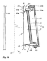
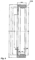
- Fig. 1b shows a vertical section of a first embodiment of the fireplace 4 in the region of the nozzle 3.
- the in Fig. 1b Closure device 1 shown has an outer lid 12, which comprises a lid, consisting of a ceramic material. For reasons the clarity is the lightweight concrete shell 41 in Fig. 1b not shown.
- the nozzle 3 is shown enlarged relative to the exhaust duct 2.
- the Schamotterohrs 21 extends, as already mentioned above, the vertical exhaust shaft 2.
- the Schamotterohr 21, ie the shaft wall 21 of the exhaust shaft 2 is broken through the shaft wall opening 22.
- the nozzle 3 is arranged on the outer side 21 a of the Schamotterohrs 21 and opens with its inner end in the region of the shaft wall opening 22.
- the facing away from the exhaust shaft 2 front end of the nozzle 3, ie the outwardly projecting front end forms an outer end face of the nozzle. 3 ,
- the nozzle 3 opens at an acute angle in the Schamotterohr 21 so that liquid, which is located in the nozzle 3, flows by gravity into the Schamotterohr 21.
- the longitudinal axis 31 of the nozzle 3 with the longitudinal central axis 23 of the exhaust shaft 2 includes an acute angle ⁇ of about 80 degrees.
- the closure device 1 comprises an inner lid 11 made of ceramic material, which is arranged in the shaft wall opening 22 and arranged with a portion inside the nozzle 3.
- the closure device 1 further comprises an outer cover 12 made of ceramic material, which is arranged with an inner portion within the nozzle 3 and with an outer portion on the outer end side of the nozzle 3.
- the closure device 1 comprises an insulating element 13 made of a fiber insulating material, which is disposed within the nozzle 3 between the inner lid 11 and the outer lid 12.
- the engaging in the shaft wall opening 22 portion of the inner lid 11 has an end face that matches the curvature of the Inner side 21i of the shaft wall 21 is curved and in the closed position is aligned in the inner side 21i of the shaft wall 21 is formed.
- the clear diameter of the nozzle 3 corresponds to the clear diameter of the shaft wall opening 22.
- the cross section of the nozzle perpendicular to its longitudinal central axis is circular. Also circular is the cross section of the exhaust shaft 2.
- the nozzle 3 is not arranged congruent to the shaft wall opening 22, but eccentric to this. As a result, covers the shaft wall 21 at the upper vertex of the nozzle 3 from a portion of the nozzle cross-section, forming a stop for the inner lid 11.
- the nozzle 3 is offset from the shaft wall 21 upwards. This avoids an undercut in which any condensate that might accumulate is avoided.
- the inner lid 11 has along its edge a circumferential groove into which a sealing cord 112 is inserted.
- the sealing cord seals a circumferential gap between the inner lid 11 and the inside of the nozzle 3.
- the diameter of the sealing cord is e.g. 4 mm.
- the outer lid 12 includes a lid made of a ceramic material and two sealing members 122a, 122b.
- the lid has a portion which is disposed within the nozzle 3, and a portion which is outside the nozzle 3, namely on the outer end side of the nozzle 3, is arranged.
- the outer cover 12 has at the disposed within the nozzle 3 portion along its edge a circumferential groove into which a sealing cord 122a is inserted.
- the sealing cord seals a circumferential gap between the outer cover 12 and the inside of the nozzle 3.
- the diameter of the sealing cord is for example 12 mm.
- the outer cover 12 also has a sealing collar 122b, which is arranged in the region of the outer end side of the connecting piece 3 around the outer circumference of the connecting piece 3 and covers the side of the cover facing away from the exhaust shaft 2 annularly.
- This sealing collar 122b is pressed by a clamping band 123 against the outer circumference of the nozzle 3 and thereby held.,
- the sealing collar 122b also seals the circumferential gap between the outer lid 12 and the inside of the nozzle 3 from.
- the insulating element 13 is located inside the nozzle 3 between the inner lid 11 and the outer lid 12.
- the insulating element is made of a heat-insulating, heat-resistant material, e.g. an insulation mat made of soft, elastic fibrous insulation materials (glass or ceramic fibers) or of harder insulating materials (stone or glass wool).
- insulating element 13 is an insulating plate or - disc with a circular circumference.
- the diameter of the Dämmelements 13 is up to about 5 mm larger than the inner diameter of the nozzle 3. That is, assuming an inner diameter of the nozzle 3 of 180 mm, the diameter of the Dämmelements 13 is in a range between 180 and 185 mm.
- the thickness of the Dämmelements can be up to 50 mm, preferably it is in a range of 30 mm.
- the insulating element 13 In order to use the insulating element 13 in its position within the nozzle 2 and to be able to remove it from its position again, the insulating element 13 has a grip band, which is firmly connected to the insulating element.
- the grip band is also made of a heat-resistant material.
- the grip band may extend over the entire diameter of the Dämmelements 13 or be formed as a loop on the Dämmusion.
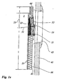
- Fig. 1c shows a vertical section of a second embodiment of the fireplace 4 in the region of the nozzle 3.
- the in Fig. 1c The closure device 1 shown has an outer cover 12 which comprises a cover consisting of metal.
- the vertical section shows the exhaust gas shaft 2 with its longitudinal central axis 23.
- the shaft wall 21 of the exhaust shaft 2 is the shaft wall opening 22.
- the closure device 1 is arranged in which the shaft wall opening 22 surrounding nozzle 3 with the longitudinal central axis 31, the closure device 1 is arranged.
- the closure device 1 comprises an inner lid 11 made of a ceramic material, an outer lid 12 made of metal and an insulating element 13 between the inner lid 11 and the outer lid 12.
- Fig. 1c shows that the outwardly projecting front end of the nozzle 3 ends within the flue 43.
- the through hole formed therein which is closed with the mantle closure 42.
- Fig. 1d shows a horizontal section through a three-shell embodiment of the chimney 4, which on the in Fig. 1a based bivalve embodiment is based.
- three-shell embodiment has an arranged inside the chimney flue 43 insulating shell 44, which is arranged adjacent to the shaft wall 21 and the shaft wall 21 surrounds.
- the chimney 4 therefore has an inner shell 21, an insulating shell 44 and an outer shell 41. Between the outside of the insulating shell 44 and the inside of the outer shell 41 remains in the chimney 43 a free space that can serve as a supply air duct.
- the insulating shell 44 may be made of a heat-insulating, heat-resistant material, such as an insulating mat made of soft, elastic fibrous insulating materials (glass or ceramic fibers) or harder insulating materials (stone or glass wool).
- Fig. 1e shows a vertical section through a three-shell embodiment of the chimney 4, which on the in Fig. 1c based bivalve embodiment is based.
- three-shell embodiment has an arranged inside the chimney flue 43 insulating shell 44, which is arranged adjacent to the shaft wall 21 and the shaft wall 21 surrounds.
- the insulating shell 44 rests at least in a partial area on the outer circumference of the nozzle 3.
- the nozzle 3 passes through the insulating shell 44 such that the cover 12 is accessible via the jacket stone closure, ie when the jacket stone closure 42 is lifted out.
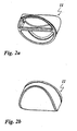
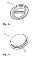
- Fig. 2a shows a perspective view of the side facing away from the exhaust duct 2 side of the inner lid 11.
- the lid is made of a ceramic material. It is designed as an open hollow body and has a horizontally extending handle bar on which the inner lid 11 can be used for insertion into and removal from its position.
- the narrow web on the upper edge of the lid 11 has the projection which comes to rest on the outer side 21 a of the shaft wall 21.
- the outer lid 12 is designed as a plug-in element.
- Fig. 2b shows a perspective view of the exhaust duct 2 facing side of the inner lid 11.
- This page has a curvature, which corresponds to the course of the shaft wall 21 in the region of the shaft wall opening 22.
- Fig. 2c shows a plan view of the side facing away from the exhaust duct 2 side of the inner lid eleventh
- Fig. 2d shows a section of the inner lid 11 along in Fig. 2c specified section line AA.
- Fig. 2e shows a plan view of the edge of the inner lid eleventh
- Table 1 are for in the FIGS. 2a to 2e shown inner lid 11 possible component dimensions, corresponding to the reference numerals ID1, ID2, ID3, ID4, ID5, ⁇ , R1, R2 listed. These dimensions represent preferred dimensions.
- Table 1 ID1 ID2 ID3 ID4 ID5 ⁇ R1 R3 77 mm 11 mm 170 mm 8 mm 177 mm 5.8 ° 98.5 mm 90.5 mm
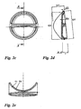
- Fig. 3a shows a perspective view of the side facing away from the exhaust duct 2 side of the outer lid 12.
- the lid is made of a ceramic material. It is designed as an open hollow body and has a horizontally extending handle bar on which the outer cover 12 can be used for insertion into and removal from its position.
- the outer lid 12 is designed as a rotary closure.
- Fig. 3b shows a perspective view of the exhaust gas shaft 2 facing side of the outer lid 12.
- This page has a flat surface on which the insulating element 13 comes to rest.
- the outer cover 12 has an outer edge, which comes to rest on the outer end side of the nozzle.
- the outer cover 12 has at the portion disposed within the nozzle 3 an edge along which a circumferential groove 124 is arranged. In this groove 124 a sealing cord is arranged.
- Fig. 3c shows a plan view of the side facing away from the exhaust duct 2 side of the outer lid 12th
- Fig. 3d shows a section of the outer lid 12 along in FIG Fig. 3c specified section line AA.
- Fig. 3e shows a plan view of the edge of the outer lid 12th
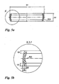
- Fig. 4a shows a section of an outer cover 12 made of metal along the axis of symmetry of the outer lid 12.
- the outer cover 12 has two corresponding in shape to each other metal shells with circular outer circumference, which can be moved by means of a screw along the axis of symmetry toward or away from each other ,
- each of the metal shells has an angle profile, which together form a circumferential groove.
- an annular Deckelauchauchdichtung is arranged, whose edges are arranged in each one of the angle sections.
- the Deckelauchauchdichtung has a small outwardly facing bulge, in whose vertex a knob is arranged.
- the lid compression seal is made of silicone, for example.
- the metal lid 12 is inserted into the neck 3, that the outer periphery of the outer metal shell rests against the outer end side of the nozzle 3 and the Deckelstauchdichtung the inside of the nozzle 3 is opposite. Now, if the metal shells shifted toward each other, the lid compression seal, the already preformed bulge following, bulges outward and seals the gap between the outer lid and the inside of the nozzle 3.
- Fig. 4b shows the in Fig. 4a specified section Y in an enlarged view.
- Table 3 are for in the FIGS. 4a and 4b shown outer cover 12 possible component dimensions for seven different sizes, corresponding to the reference numerals P1 to P8, R4 listed. These dimensions are preferred dimensions. Dimensions are in millimeters. Table 3 nominal width P1 P2 P3 P4 P5 P6 P7 P8 R4 80 100 24 50 69 76 22 1 4 1 100 120 24 60 89 96 22 1 4 1 120 140 30 70 109 116 22 1 4 1 140 160 30 70 129 136 22 1 4 1 160 180 30 70 149 156 22 1 4 1 180 200 30 105 169 176 22 1 4 1 200 220 30 105 189 196 22 1 4 1
- Fig. 5a shows a section of an alternative annular Deckelauchauchdichtung.
- the lid compression seal is made of a fluororubber, eg Viton ® .
- Fig. 5b shows the in Fig. 5a specified section X in an enlarged view.
- Fig. 6 shows a section of a sealing collar 122b.
- the sealing collar has an outer portion, which covers the outwardly, ie the side facing away from the exhaust duct 21 side of the outer lid 12 annular.
- the sealing collar has an inner portion which is disposed over the outside of the nozzle 3.
- the sealing collar In order to prevent accidental slipping of the sealing sleeve from the outside of the neck 3, the sealing collar on the inside of the inner portion on two circumferential beads.
- a clamping band can be arranged on the outer circumference of the sealing sleeve. By tightening the clamping band, the sealing sleeve is pressed gas-tight against the outside of the nozzle 3.
Landscapes
- Engineering & Computer Science (AREA)
- Mechanical Engineering (AREA)
- General Engineering & Computer Science (AREA)
- Thermal Insulation (AREA)
- Separation Of Particles Using Liquids (AREA)
- Incineration Of Waste (AREA)
- Chimneys And Flues (AREA)
- Exhaust Silencers (AREA)
- Gasket Seals (AREA)
Description
- Die Erfindung betrifft einen Kamin gemäß dem Oberbegriff des Anspruchs 1. Ein solcher Kamin ist z.B. aus
DE 10 2006 050 401 A1 bekannt. - Üblicherweise ist in einer Schachtwand eines Abgasschachts, z.B. einem keramischen Abgasrohr, eine seitliche Schachtwandöffnung vorgesehen, durch die ein Zugang zu dem Abgasschacht ermöglicht wird, z.B. zur Reinigung, Revision oder Wartung des Abgasschachts. Es hat sich bewährt, im Bereich der Schachtwandöffnung einen Stutzen auszubilden, der mit einer wiederverschließbaren Tür versehen ist. Derartige Stutzen können entweder aus einem Stück mit dem keramischen Abgasrohr ausgebildet werden, z.B. durch isostatisches Pressen, oder erst nach dem Brennen des Abgasrohrs, durch Ausschneiden der seitlichen Schachtwandöffnung und sogenanntes Angamieren von geeigneten keramischen Ergänzungs-Formstücken an das Abgasrohr mit Hilfe eines Kitts oder Klebers. Die wiederverschließbare Tür zum Verschließen des Stutzens wird auch Putz- oder Revisionstür genannt.
- Bei Unterdruck-Abgasanlagen, d.h. Abgasanlagen, bei deren Betrieb der Druck im Abgasschacht niedriger ist als außerhalb, ist die Gefahr, dass Abgase ungewollt über die Revisionsöffnung in angrenzende Aufenthaltsräume gelangen, aufgrund der Druckverhältnisse sehr gering. Bei Unterdruck-Abgasanlagen ist daher als Revisionstür zum Verschließen des Stutzens eine Metall- oder Keramiktür mit geringer Gasdichtheit, d.h. einer Leckrate in einem Bereich von 2,0 bis 3,0 l/(s m2), in der Regel ausreichend. Eine Abdichtung der Putztür zum Stutzen erfolgt beispielsweise mittels einer dichtenden Metallfeder, die durch einen Schraubmechanismus gegen die Innenseite des Stutzens verspannt wird. Aufgrund der hohen Temperaturbeständigkeit der verwendeten Materialien (Metall, Keramik) sind diese Verschlusssysteme rußbrandbeständig und auch bei höheren Abgastemperaturen, z.B. im Bereich von 400 °C, einsetzbar (z.B. Temperaturklasse T400 nach EN 1443).
- Bei Überdruck-Abgasanlagen, d.h. Abgasanlagen, bei deren Betrieb der Druck im Abgasschacht höher ist als außerhalb, muss die Revisionstür zum Verschließen des Stutzens höheren Anforderungen an die Gasdichtheit genügen. Um die zulässigen Leckraten in einem Bereich von 0,006 l/(s m2) einhalten zu können, sind in der Regel aus Kunststoffen gefertigte Dichtungsringe nötig, die den Spalt zwischen der Revisionstür und dem Stutzen abdichten. Ein derartiges Verschlusssystem kann z.B. als eine zweischalige Metalltür mit einer zwischen den Schalen angeordneten, umlaufenden Elastomer-Dichtung ausgebildet sein. Durch Anziehen einer Schraube werden die beiden Schalen aufeinander zu bewegt, was zu einer Auswölbung der Elastomer-Dichtung nach außen, d.h. gegen die Innenseite des rohrförmigen Stutzens, führt. Aufgrund der niedrigen Temperaturbeständigkeit der verwendeten Dichtmaterialien (Kunststoffe) sind diese Verschlusssysteme nicht rußbrandbeständig und nur bei niedrigeren Abgastemperaturen, z.B. im Bereich von 200 °C, einsetzbar (z.B. Temperaturklasse T200 nach EN 1443).
- Moderne Holzfeuerstätten, z.B. Pellets- oder Hackschnitzelheizungen mit Gebläse, benötigen häufig eine Abgasanlage, die die Vorteile der beiden vorgenannten Verschlusssysteme vereint, d.h. die gleichzeitig rußbrandbeständig ist und höheren Anforderungen an die Gasdichtheit genügt.
- Der Erfindung liegt daher die Aufgabe zugrunde, einen Kamin bereitzustellen, der rußbrandbeständig ist und höheren Anforderungen an die Gasdichtheit genügt.
- Diese Aufgabe wird durch den Gegenstand des Anspruchs 1 gelöst.
- Diese Lösung sieht vor, dass die Verschlussvorrichtung mindestens dreiteilig ist. Sie umfasst einen inneren Deckel, ein Dämmelement und einen äußeren Deckel. Der innere Deckel bildet den Abschluss der Verschlussvorrichtung zu dem heißen Abgasschacht hin und kann so ausgebildet werden, dass er in der Schachtwandöffnung dort die Schachtwand quasi ersetzt. Die zur Schachtwand hin gewandte Innenseite des inneren Deckels ist so ausgebildet, dass sie eine mit der Schachtwand fluchtende Abschlussfläche bildet.
- Das Dämmelement dient primär zur Wärmedämmung, kann aber auch andere Funktionen haben, z.B. Schalldämmung und in gewissem Umfang auch Abdichtung.
- Der äußere Deckel schließt den Stutzen nach außen hin ab und kann Dichtelemente enthalten. Vorzugsweise ergibt sich durch diese äußere Anordnung des äußeren Deckels und das vorgeschaltete Dämmelement, dass der äußere Deckel eine relativ niedrige Temperaturbelastung hat. Der äußere Deckel eignet sich damit besonders zur Abdichtung mithilfe von zwischengeschalteten Dämmelementen.
- Bei dem Kamin handelt es sich um eine Schomsteineinrichtung als Abgasanlage zum Anschluss von Feuerstätten, z.B. Öfen für diverse Brennstoffe. Der Abgasschacht, der mit den Feuerstätten zum Abzug des Abgases zu verbinden ist, kann als Rohr, vorzugsweise Muffenrohr, oder auch als gemauerter Schacht ausgebildet sein. Der Kamin kann einschalig oder mehrschalig ausgebildet sein.
- Bei den einschaligen Ausführungen ist der Kamin lediglich als Abgasschacht, begrenzt durch die Schachtwand, ausgebildet. Die Schachtwand wird durch die Rohrwand bzw. die gemauerte Schachtwand gebildet. Der Stutzen der Verschlussvorrichtung mündet mit seinem inneren Ende unmittelbar in den Abgasschacht und ragt mit seinem äußeren Ende vom Abgasschacht nach außen.
- Wenn der Kamin mehrschalig ausgebildet ist, umfasst er eine Außenschale und eine Innenschale, wobei die Innenschale in ihrem Innenraum den Abgasschacht bildet Die Außenschale bildet einen äußeren Kaminschacht, in welchem die Innenschale mit dem Abgasschacht angeordnet ist. Die Verschlussvorrichtung sieht vor, dass der Stutzen mit seinem äußeren Ende in dem äußeren Kaminschacht endet oder die Außenschale durchgreift und mit seinem inneren Ende im Bereich der Schachtwandöffnung in die Innenschale mündet. Bei den mehrschaligen Kaminen kann der Stutzen länger ausgebildet sein als bei einschaligen Kaminen. Daher ist mehr Raum für die in dem Stutzen angeordneten Bauteile der Verschlussvorrichtung. Falls der Stutzen mit seinem äußeren Ende in dem Kaminschacht endet, ist es dabei bevorzugt, wenn die Außenschale in einem Bereich, in dem eine über das äußere Ende des Stutzens hinaus gedachte Verlängerung des Stutzens entlang seiner Längsachse auf die Außenschale trifft, eine mit einem Mantelsteinverschluss verschließbare Durchgangsöffnung aufweist.
- Insbesondere kann der Kamin dreischalig ausgebildet sein, wobei er eine Außenschale, eine Innenschale und eine zwischen der Außenschale und der Innenschale angeordnete Dämmschale umfasst und wobei die Innenschale in ihrem Innenraum den Abgasschacht bildet. Die Dämmschale dient der thermischen Isolierung des Abgasschachts, z.B. zur Verhinderung bzw. Reduzierung von Kondensaten. Die Dämmschale ist in dem zwischen der Außenschale und der Innenschale gebildeten Hohlraum angeordnet. Vorzugsweise ist die Dämmschale unmittelbar auf der Innenschale angeordnet. Zwischen der Außenseite der Dämmschale und der Innenseite der Außenschale ist ein freier Raum ausgebildet, der als Zuluftkanal dienen kann.
- Dieses Konzept von ein- oder mehrschaligen Kaminen mit der erfindungsgemäßen Verschlussvorrichtung erlaubt Ausführungen der Abgasanlage, die sowohl für den Überdruckbereich, z.B. für einen Überdruck von 200 Pa, geeignet ist als auch Rußbrandbeständigkeit aufweist. Messungen haben gezeigt, dass mit einem Kamin gemäß der vorliegenden Erfindung bei einem Überdruck von 200 Pa eine Leckrate von 0,006 l/(s 2) bzw. 21,6 l/(h m2) nicht überschritten wird.
- Mit den betreffenden Ausführungen des Kamins ist es möglich, die thermischen Belastungsprüfungen (Rußbrand, Heizversuch) nach DIN EN 13216 und 13063 T1 erfolgreich zu erfüllen.
- In einer bevorzugten Ausführung der Erfindung weist der in die Schachtwandöffnung eingreifende Abschnitt des inneren Deckels ein Stirnende auf, das mit der Innenseite der Schachtwand fluchtend ausgebildet ist. Durch den formschlüssigen Anschluss des inneren Deckels an die Schachtwand ist kein Vorsprung oder Rücksprung vorhanden, wo sich die Wärmeströmung des im Abgasschacht strömenden heißen Abgasstroms fangen kann. Dadurch wird verhindert, dass sich die Bauteile im Stutzen zu stark erhitzen und dadurch Schaden nehmen.
- Es ist besonders vorteilhaft, wenn der Stutzen exzentrisch zu der Schachtwandöffnung außen an der Schachtwand im Bereich der Schachtwandöffnung aufgesetzt angeordnet ist. Insbesondere ist es vorteilhaft, wenn der Stutzen in Bezug auf die Schachtwandöffnung exzentrisch so weit nach oben verschoben außen an der Schachtwand aufgesetzt angeordnet ist, so dass der Stutzen ist in seinem Anschlussbereich, mit dem er auf der Schachtwand aufgesetzt ist, nicht deckungsgleich zentrisch auf der Schachtwandöffnung angeordnet ist, sondern versetzt zu dieser. Damit wird ein Hinterschnitt im unteren Bereich der Anschlussstelle vermieden, so dass sich im Stutzen auftretendes Kondensat dort nicht sammeln kann sondern in den Abgasschacht abfließt.
- Die exzentrische Anordnung kann so ausgebildet sein, dass die Schachtwand am oberen Scheitelpunkt des Stutzens in den Öffnungsquerschnitt des Stutzens hineinragt und damit einen Anschlag für den inneren Deckel bildet. Der Anschlag kann also dazu genutzt werden, den in die Schachtwandöffnung eingreifenden Abschnitt des inneren Deckels sicher in der Schachtwandöffnung zu halten. Dadurch wird verhindert, dass der innere Deckel in den Abgasschacht fällt.
- Bei einer bevorzugten Ausführung weist die Verschlussvorrichtung eine Halteeinrichtung aufweist, durch die der innere Deckel in einer vorgegebenen Position gehalten wird. Es ist möglich, dass die Halteeinrichtung einen Anschlag und einen an dem Anschlag in Anlage bringbaren Gegenanschlag aufweist, wobei der Anschlag am inneren Deckel angeordnet ist und der Gegenanschlag an der Schachtwand und/oder an dem Stutzen angeordnet ist. Es ist möglich, dass die Halteeinrichtung einen Anschlag und einen mit dem Anschlag zusammenwirkenden Gegenanschlag aufweist. Der Anschlag ist am inneren Deckel angeordnet und kommt bei korrekter Position des inneren Deckels an dem an der Schachtwand und/oder an dem Stutzen angeordneten Gegenanschlag zur Anlage. Besonders bevorzugt ist es, wenn die Halteeinrichtung als ein am Außenumfang des inneren Deckels angeordneter Vorsprung ausgebildet ist, der an der Außenseite der Schachtwand zur Anlage kommt. Vorzugsweise ist der Vorsprung in einem Teilbereich, vorzugsweise einem oberen Abschnitt, des inneren Deckels angeordnet.
- Vorzugsweise ist der Stutzen so außen an der Schachtwand angeordnet, dass im Stutzen auftretendes Kondensat in den Abgasschacht abfließen kann. Es ist möglich, dass die Längsachse des Stutzens zu dem Abgasschacht geneigt ist. Dadurch fließt Flüssigkeit von selbst aus dem Stutzen in den Abgasschacht. Vorzugsweise schließt die Längsachse des Stutzens mit der Längsachse des Abgasschachts einen spitzen Winkel, z.B. von 80 bis 90 Grad, insbesondere einen Winkel von 85 bis 87 Grad, ein.
- Der innere Deckel ist zumindest teilweise aus einem keramischen Material ausgebildet. Die Herstellung des inneren Deckels kann in einem Gieß- oder Druckgießverfahren für Bauteile im Kaminbau erfolgen.
- In einer bevorzugten Ausgestaltung der Erfindung weist der innere Deckel ein Dichtelement auf, das einen umlaufenden Spalt zwischen dem inneren Deckel und der Innenseite des Stutzens, d.h. der Innenwand des Stutzens, abdichtet. Vorzugsweise ist das Dichtelement als eine Dichtschnur oder ein Dichtband ausgebildet.
- Vorteilhaft ist es auch, wenn das Dichtelement des inneren Deckels in einer umlaufenden Nut des innerhalb des Stutzens angeordneten Abschnitts des inneren Deckels angeordnet ist.
- Darüber hinaus ist es möglich, dass der äußere Deckel einen Deckel, bestehend aus einem keramischen Material und/oder Metall, und mindestens ein Dichtelement aufweist. Das mindestens eine Dichtelement ist so ausgebildet, dass es einen umlaufenden Spalt zwischen dem äußeren Deckel und der Innenseite des Stutzens abdichtet.
- Vorzugsweise umfasst der äußere Deckel einen zwei gegeneinander verschiebbare Schalen aufweisenden Metalldeckel. Das mindestens eine Dichtelement ist vorzugsweise als eine zwischen den zwei Schalen angeordnete Deckelstauchdichtung ausgebildet ist.
- Weiter vorzugsweise weist der äußere Deckel einen Keramikdeckel auf, und das mindestens eine Dichtelement umfasst eine Dichtmanschette, die an der Außenseite des Stutzens angeordnet ist und die von dem Abgasschacht abgewandte Seite des Keramikdeckels zumindest teilweise, vorzugsweise ringförmig entlang des äußeren Umfangs des Stutzens, überdeckt. Vorzugsweise besteht die Dichtmanschette aus einem Elastomer. Bei einer bevorzugten Ausführung weist der äußere Deckel ein Klemmband auf, das die Dichtmanschette gegen die Außenseite des Stutzens presst.
- Besonders bevorzugt ist es, wenn das mindestens eine Dichtelement des äußeren Deckels eine Dichtschnur oder ein Dichtband umfasst, die bzw. das in einer umlaufenden Nut des innerhalb des Stutzens angeordneten Abschnitts des äußeren Deckels angeordnet ist.
- Es ist auch möglich, dass das Dämmelement aus einem wärmedämmenden Material ausgebildet ist. Vorzugsweise weist das Dämmelement eine Dämmmatte aus faserhaltigen Dämmstoffen auf.
- Es ist möglich, dass das Dämmelement als Dämmplatte mit einem an der dem Abgasschacht abgewandten Seite der Dämmplatte angeordneten Griffband ausgebildet ist.
- Vorzugsweise ist die Verschlussvorrichtung bis zu einem Überdruck von 200 Pa im Abgasschacht gegenüber dem Umgebungsdruck des Kamins dicht ist. Die Verschlussvorrichtung ist rußbrandbeständig. Vorzugsweise weist die Verschlussvorrichtung eine Leckrate von maximal 0,006 l/(s m2) auf.
- In einer vorteilhaften Ausgestaltung der Erfindung wird der innere Deckel durch ein Gießverfahren hergestellt.
- Vorzugsweise weist die Schachtwandöffnung einen runden Umfang bzw. Querschnitt auf. Des weiteren ist es von Vorteil, wenn der Stutzen einen runden Querschnitt aufweist. Es ist auch möglich, dass der innere Deckel und/oder der äußere Deckel und/oder das Dämmelement einen runden Querschnitt aufweist bzw. aufweisen. Es ist von Vorteil, wenn der Durchmesser des Dämmelement genauso groß oder geringfügig größer als der Innendurchmesser des Stutzens ist. Dadurch liegt das Dämmelement fest an der Innenseite des Stutzens an. Auf diese Weise ist eine gute thermische Abdichtung auch in den Randbereichen des Dämmelements zu erzielten.
- In einer vorteilhaften Ausgestaltung der Erfindung ist der äußere Deckel als ein Drehverschluss ausgebildet. Durch eine Drehbewegung kann der äußere Deckel in seine Position im Stutzen eingedreht werden. Ebenfalls durch eine Drehbewegung kann der äußere Deckel aus seiner Position im Stutzen herausgedreht werden. Vorzugsweise weisen, wenn der äußere Deckel als Drehverschluss ausgebildet ist, der Stutzen und der äußere Deckel einen runden Querschnitt auf.
- In einer weiteren vorteilhaften Ausgestaltung der Erfindung ist der innere Deckel als ein Steckteil ausgebildet ist. Der innere Deckel wird ohne Drehbewegung in den Stutzen eingeführt und durch eine Steckbewegung in seine vorgegebene Position gebracht. Zum Herausnehmen des inneren Deckels wird der innere Deckel durch Zug aus seiner Position gelöst und aus dem Stutzen herausgeführt.
- Weitere Merkmale, Einzelheiten und Vorteile der Erfindung ergeben sich aus der folgenden Beschreibung von Ausführungsbeispielen erfindungsgemäßer Schornsteine anhand der Figuren. Es zeigen
- Fig. 1
- Schnitte eines Abgasschachts mit einem außen angeordneten Stutzen mit einer Verschlussvorrichtung;
- Fig. 2
- Ansichten und Schnitte eines inneren Deckels aus einem keramischen Material;
- Fig. 3
- Ansichten und Schnitte eines äußeren Deckels aus einem keramischen Material;
- Fig. 4
- Schnitte eines äußeren Deckels aus Metall;
- Fig. 5
- Schnitte eines Dichtelements des äußeren Deckels; und
- Fig. 6
- einen Schnitt einer Dichtmanschette.
- Bei den in
Fig. 1 dargestellten Ausführungsbeispielen handelt es sich um einen Kamin 4 mit einer in einem seitlichen Stutzen 3 angeordneten rauchdichten Verschlussvorrichtung 1. -
Figur 1a zeigt einen Horizontalschnitt durch den Kamin 4. Ein Leichtbetonmantel 41 mit quadratischem Querschnitt bildet eine äußere Schale (= Außenschale) des Kamins 4, und in dem Innenraum des Leichtbetonmantels 41 ist ein vertikaler Kaminschacht 43 ausgebildet. In diesem Kaminschacht 43 ist koaxial ein Abgasrohr angeordnet, das als Schamotterohr 21 ausgebildet ist. Das Schamotterohr 21 hat kreisrunden Querschnitt und bildet eine innere Schale (= Innenschale) des Kamins 4. Die vertikale Längsmittelachse des Schamotterohrs 21 fällt mit der vertikalen Längsmittelachse des in dem Leichtbetonmantel 41 ausgebildeten Kaminschachts 43 zusammen. Das Innere des Schamotterohrs 21 bildet einen Abgasschacht 2 zum Abzug von Rauchgas von einer Feuerstätte ins Freie. Das Schamotterohr 21 bildet die Schachtwand 21 des Abgasschachts 2. Die Innenseite 21i der Schachtwand 21 bildet die Begrenzungsfläche des Abgasschachts 2. Die vertikale Längsmittelachse des Schamotterohrs fällt mit der vertikalen Längsmittelachse 23 des Abgasschachts 2 zusammen. Die Schachtwand 21 weist eine kreisrunde Schachtwandöffnung 22 auf, die die Schachtwand 21 durchgreift. - An der Außenseite 21a der Schachtwand 21 ist ein rohrförmiger Stutzen 3 angeordnet, der im Bereich der Schachtwandöffnung 22 mündet. Der Stutzen 3 kann an der Außenseite 21a der Schachtwand 21 einstückig angeformt sein oder nachträglich an der Außenseite der Schachtwand 21 befestigt werden, z. B. durch eine keramische Klebeverbindung. Der Stutzen 3 ragt nach außen, das heißt vom Schamotterohr 21 in Richtung des Leichtbetonmantels 41. Das nach außen ragende Stirnende des Stutzens 3 endet bei dem dargestellten Ausführungsbeispiel innerhalb des Kaminschachts 43. In Verlängerung der Längsmittelachse des Stutzens 3 weist der Leichtbetonmantel 41 eine darin ausgebildete Durchgangsöffnung auf, die mit einem Mantelsteinverschluss 42 verschlossen ist. Übliche Rohrdurchmesser des Stutzens 3 liegen in einem Bereich von 80 mm bis 250 mm.
- Ein zwischen dem Schamotterohr 21 und dem Leichtbetonmantel 41 verbleibender Hohlraum des Kaminschachts 43 kann als Zuluftkanal genutzt werden. Zusätzlich oder alternativ kann in dem Hohlraum eine Wärmedämmschicht zur thermischen Isolierung des Abgasschachts 2 angeordnet werden.
- Der Stutzen 3 kommuniziert mit der Schachtwandöffnung 22. Bei herausgenommenem Mantelsteinverschluss 42 wird der Stutzen 3 mit der Verschlussvorrichtung 1 von außen her zugänglich. Dies ist für die Wartung und Reinigung des Abgasschachts 2 erforderlich. In der Schachtwandöffnung 22 und in dem Stutzen 3 ist die Verschlussvorrichtung 1 angeordnet, durch die der Verbindungskanal gasdicht verschlossen wird. Aus Gründen der Übersichtlichkeit ist die Verschlussvorrichtung 1 in
Fig. 1a nicht dargestellt. -
Fig. 1b zeigt einen Vertikalschnitt eines ersten Ausführungsbeispiels des Kamins 4 im Bereich des Stutzens 3. Die inFig. 1b dargestellte Verschlussvorrichtung 1 weist einen äußeren Deckel 12 auf, der einen Deckel, bestehend aus einem keramischen Material, umfasst. Aus Gründen der Übersichtlichkeit ist der Leichtbetonmantel 41 inFig. 1b nicht dargestellt. Um das Erkennen der Details der Verschlussvorrichtung 1 zu erleichtern, ist der Stutzen 3 gegenüber dem Abgasschachts 2 vergrößert dargestellt. Innerhalb des Schamotterohrs 21 verläuft, wie oben bereits erwähnt, der vertikale Abgasschacht 2. Das Schamotterohr 21, d.h. die Schachtwand 21 des Abgasschachtes 2, ist durch die Schachtwandöffnung 22 durchbrochen. Der Stutzen 3 ist an der Außenseite 21 a des Schamotterohrs 21 angeordnet und mündet mit seinem innenliegenden Ende im Bereich der Schachtwandöffnung 22. Das von dem Abgasschacht 2 abgewandte Stirnende des Stutzens 3, d.h. das nach außen ragende Stirnende, bildet eine äußere Stirnseite des Stutzens 3. - Der Stutzen 3 mündet mit spitzem Winkel in das Schamotterohr 21, so dass Flüssigkeit, die sich in dem Stutzen befindet 3, durch die Schwerkraft in das Schamotterohr 21 fließt. In dem ausgeführten Ausführungsbeispiel schließt die Längsachse 31 des Stutzens 3 mit der Längsmittelachse 23 des Abgasschachts 2 einen spitzen Winkel α von ca. 80 Grad ein.
- Die Verschlussvorrichtung 1 umfasst einen inneren Deckel 11 aus keramischen Material, der in die Schachtwandöffnung 22 eingreifend und mit einem Abschnitt innerhalb des Stutzens 3 angeordnet ist. Die Verschlussvorrichtung 1 umfasst darüber hinaus einen äußeren Deckel 12 aus keramischen Material, der mit einem inneren Abschnitt innerhalb des Stutzens 3 und mit einem äußeren Abschnitt an der äußeren Stirnseite des Stutzens 3 angeordnet ist. Außerdem umfasst die Verschlussvorrichtung 1 ein Dämmelement 13 aus einem Faserdämmstoff, das innerhalb des Stutzens 3 zwischen dem inneren Deckel 11 und dem äußeren Deckel 12 angeordnet ist.
- Der in die Schachtwandöffnung 22 eingreifende Abschnitt des inneren Deckels 11 weist eine Stirnfläche auf, die passend zu der Wölbung der Innenseite 21i der Schachtwand 21 gewölbt ist und in der Schließstellung fluchtend in die Innenseite 21i der Schachtwand 21 ausgebildet ist.
- Der lichte Durchmesser des Stutzens 3 entspricht dem lichten Durchmesser der Schachtwandöffnung 22. Der Querschnitt des Stutzens senkrecht zu seiner Längsmittelachse ist kreisförmig. Ebenfalls kreisförmig ist der Querschnitt des Abgasschachtes 2. Im Bereich der Mündung des Stutzens 3 in den Abgasschacht 2 ist der Stutzen 3 nicht deckungsgleich zu der Schachtwandöffnung 22 angeordnet, sondern exzentrisch zu dieser. Dadurch deckt die Schachtwand 21 am oberen Scheitelpunkt des Stutzens 3 einen Teil des Stutzenquerschnitts ab, unter Bildung eines Anschlags für den inneren Deckel 11. Am unteren Scheitelpunkt des Stutzens 3 ist der Stutzen 3 gegenüber der Schachtwand 21 nach oben versetzt. Damit wird ein Hinterschnitt, in dem sich eventuell auftretendes Kondensat sammeln könnte, vermieden.
- Der innere Deckel 11 weist entlang seiner Kante eine umlaufende Nut auf, in die eine Dichtschnur 112 eingelegt ist. Die Dichtschnur dichtet einen umlaufenden Spalt zwischen dem inneren Deckel 11 und der Innenseite des Stutzens 3 ab. Der Durchmesser der Dichtschnur beträgt z.B. 4 mm.
- Der äußere Deckel 12 umfasst einen Deckel, bestehend aus einem keramischen Material, und zwei Dichtelemente 122a, 122b. Der Deckel weist einen Abschnitt auf, der innerhalb des Stutzens 3 angeordnet ist, sowie einen Abschnitt, der außerhalb des Stutzens 3, nämlich an der äußeren Stirnseite des Stutzens 3, angeordnet ist. Der äußere Deckel 12 weist an dem innerhalb des Stutzens 3 angeordneten Abschnitt entlang seiner Kante eine umlaufende Nut auf, in die eine Dichtschnur 122a eingelegt ist. Die Dichtschnur dichtet einen umlaufenden Spalt zwischen dem äußeren Deckel 12 und der Innenseite des Stutzens 3 ab. Der Durchmesser der Dichtschnur beträgt z.B. 12 mm.
- Der äußere Deckel 12 weist darüber hinaus eine Dichtmanschette 122b auf, die im Bereich der äußeren Stirnseite des Stutzens 3 um den Außenumfang des Stutzens 3 herum angeordnet ist und die von dem Abgasschacht 2 abgewandte Seite des Deckels ringförmig überdeckt. Diese Dichtmanschette 122b wird durch ein Klemmband 123 gegen den Außenumfang des Stutzens 3 gepresst und dadurch gehalten., Die Dichtmanschette 122b dichtet ebenfalls den umlaufenden Spalt zwischen dem äußeren Deckel 12 und der Innenseite des Stutzens 3 ab.
- Das Dämmelement 13 befindet sich innerhalb des Stutzens 3 zwischen dem inneren Deckel 11 und dem äußeren Deckel 12. Das Dämmelement besteht aus einem wärmedämmenden, hitzebeständigen Material, z.B. einer Dämmmatte aus weichem, elastischen faserhaltigen Dämmstoffen (Glas- oder Keramikfasern) oder aus härteren Dämmstoffen (Stein- oder Glaswolle).
- Das in
Fig. 1b dargestellte Dämmelement 13 ist eine Dämmplatte bzw. - scheibe mit kreisrundem Umfang. Der Durchmesser des Dämmelements 13 ist bis zu ca. 5 mm größer als der Innendurchmesser des Stutzens 3. Das heißt, dass bei einem angenommenen Innendurchmesser des Stutzens 3 von 180 mm der Durchmesser des Dämmelements 13 in einem Bereich zwischen 180 und 185 mm liegt. Die Dicke des Dämmelements kann bis zu 50 mm betragen, vorzugsweise liegt sie in einem Bereich von 30 mm. - Um das Dämmelement 13 in seine Position innerhalb des Stutzens 2 einsetzen und wieder aus seiner Position entfernen zu können, weist das Dämmelement 13 ein Griffband auf, das mit dem Dämmelement fest verbunden ist. Das Griffband besteht ebenfalls aus einem hitzebeständigen Material. Das Griffband kann sich über den gesamten Durchmesser des Dämmelements 13 erstrecken oder als Schleife auf der Dämmscheibe ausgebildet sein.
-
Fig. 1c zeigt einen Vertikalschnitt eines zweiten Ausführungsbeispiels des Kamins 4 im Bereich des Stutzens 3. Die inFig. 1c dargestellte Verschlussvorrichtung 1 weist einen äußeren Deckel 12 auf, der einen Deckel, bestehend aus Metall, umfasst. - Der Vertikalschnitt zeigt den Abgasschacht 2 mit seiner Längsmittelachse 23. In der Schachtwand 21 des Abgasschachts 2 befindet sich die Schachtwandöffnung 22. In dem die Schachtwandöffnung 22 umgebenden Stutzen 3 mit der Längsmittelachse 31 ist die Verschlussvorrichtung 1 angeordnet. Die Verschlussvorrichtung 1 umfasst einen inneren Deckel 11 aus einem keramischen Material, einen äußeren Deckel 12 aus Metall sowie ein Dämmelement 13 zwischen dem inneren Deckel 11 und dem äußeren Deckel 12.
- Der Vertikalschnitt in
Fig. 1c zeigt, dass das nach außen ragende Stirnende des Stutzens 3 innerhalb des Kaminschachts 43 endet. In Verlängerung der Längsmittelachse 31 des Stutzens 3 befindet sich in dem Leichtbetonmantel 41 die darin ausgebildete Durchgangsöffnung, die mit dem Mantelsteinverschluss 42 verschlossen ist. -
Fig. 1d zeigt einen Horizontalschnitt durch eine dreischalige Ausführungsform des Kamins 4, die auf der inFig. 1a gezeigten zweischaligen Ausführungsform basiert. Die inFig. 1d gezeigte dreischalige Ausführungsform weist eine innerhalb des Kaminschachts 43 angeordnete Dämmschale 44 auf, die an der Schachtwand 21 anliegend angeordnet ist und die Schachtwand 21 umgibt. Der Kamin 4 weist daher eine Innenschale 21, einen Dämmschale 44 und eine Außenschale 41 auf. Zwischen der Außenseite der Dämmschale 44 und der Innenseite der Außenschale 41 verbleibt im Kaminschacht 43 ein freier Raum, der als Zuluftkanal dienen kann. Die Dämmschale 44 kann aus einem wärmedämmenden, hitzebeständigen Material, z.B. einer Dämmmatte aus weichem, elastischen faserhaltigen Dämmstoffen (Glas- oder Keramikfasern) oder aus härteren Dämmstoffen (Stein- oder Glaswolle), bestehen. -
Fig. 1e zeigt einen Vertikalschnitt durch eine dreischalige Ausführungsform des Kamins 4, die auf der inFig. 1c gezeigten zweischaligen Ausführungsform basiert. Die inFig. 1e gezeigte dreischalige Ausführungsform weist eine innerhalb des Kaminschachts 43 angeordnete Dämmschale 44 auf, die an der Schachtwand 21 anliegend angeordnet ist und die Schachtwand 21 umgibt. Die Dämmschale 44 liegt zumindest in einem Teilbereich an dem Außenumfang des Stutzens 3 an. Der Stutzen 3 durchgreift die Dämmschale 44 so, dass der Deckel 12 über den Mantelsteinverschluss, d.h. bei herausgehobenem Mantelsteinverschluss 42 zugänglich ist. -
Fig. 2a zeigt eine perspektivische Ansicht der vom Abgasschacht 2 abgewandten Seite des inneren Deckels 11. Der Deckel besteht aus einem keramischen Material. Er ist als offener Hohlkörper ausgebildet und weist einen waagrecht verlaufenden Griffsteg auf, an dem der innere Deckel 11 zum Einsetzen in und zum Entfernen aus seiner Position gegriffen werden kann. Der schmale Steg an der oberen Kante des Deckels 11 weist den Vorsprung auf, der an der Außenseite 21a des Schachtwand 21 zur Anlage kommt. Der äußere Deckel 12 ist als Steckelement konzipiert. -
Fig. 2b zeigt eine perspektivische Ansicht der dem Abgasschacht 2 zugewandten Seite des inneren Deckels 11. Diese Seite weist eine Wölbung auf, die dem Verlauf der Schachtwand 21 im Bereich der Schachtwandöffnung 22 entspricht. Dadurch ist es möglich, den inneren Deckel 11 formschlüssig mit der Schachtwand in die Schachtwandöffnung 22 einzusetzen. Durch den breiten Steg an der unteren Kante des Deckels 11 verkantet sich der Deckel 11 in dem Stutzen 3. Auf diese Weise wird der innere Deckel 11 im Stutzen 3 sicher gehalten. -
Fig. 2c zeigt eine Draufsicht der vom Abgasschacht 2 abgewandten Seite des inneren Deckels 11.Fig. 2d zeigt einen Schnitt des inneren Deckels 11 entlang der inFig. 2c angegebenen Schnittlinie A-A.Fig. 2e zeigt eine Draufsicht der Kante des inneren Deckels 11. - In der Tabelle 1 sind für den in den
Figuren 2a bis 2e gezeigten inneren Deckel 11 mögliche Bauteil-Abmessungen, entsprechend den Bezugszeichen ID1, ID2, ID3, ID4, ID5, γ, R1, R2, aufgelistet. Diese Abmessungen stellen bevorzugte Maße dar.Tabelle 1 ID1 ID2 ID3 ID4 ID5 γ R1 R3 77 mm 11 mm 170 mm 8 mm 177 mm 5,8° 98,5 mm 90,5 mm -
Fig. 3a zeigt eine perspektivische Ansicht der vom Abgasschacht 2 abgewandten Seite des äußeren Deckels 12. Der Deckel besteht aus einem keramischen Material. Er ist als offener Hohlkörper ausgebildet und weist einen waagrecht verlaufenden Griffsteg auf, an dem der äußere Deckel 12 zum Einsetzen in und zum Entfernen aus seiner Position gegriffen werden kann. Der äußere Deckel 12 ist als Drehverschluss konzipiert. -
Fig. 3b zeigt eine perspektivische Ansicht der dem Abgasschacht 2 zugewandten Seite des äußeren Deckels 12. Diese Seite weist eine ebene Fläche auf, an der das Dämmelement 13 zur Anlage kommt. Der äußere Deckel 12 weist einen äußeren Rand auf, der an der äußeren Stirnseite des Stutzens zur Anlage kommt. Der äußere Deckel 12 weist an dem innerhalb des Stutzens 3 angeordneten Abschnitt eine Kante auf, entlang der eine umlaufende Nut 124 angeordnet ist. In dieser Nut 124 wird eine Dichtschnur angeordnet. -
Fig. 3c zeigt eine Draufsicht der vom Abgasschacht 2 abgewandten Seite des äußeren Deckels 12.Fig. 3d zeigt einen Schnitt des äußeren Deckels 12 entlang der inFig. 3c angegebenen Schnittlinie A-A.Fig. 3e zeigt einen Draufsicht der Kante des äußeren Deckels 12. - In der Tabelle 2 sind für den in den
Figuren 3a bis 3e gezeigten äußeren Deckel 12 mögliche Bauteil-Abmessungen für drei unterschiedliche Ausführungen I, II und III, entsprechend den Bezugszeichen AD1, AD2, AD3, AD4, AD5, AD6, AD7, AD8, AD9, AD10, AD11, AD12, AD13, R2, R5, R6 aufgelistet. Diese Abmessungen stellen bevorzugte Maße dar. Die Maße sind in der Einheit Millimeter angegeben. -
Fig. 4a zeigt einen Schnitt eines äußeren Deckels 12 aus Metall entlang der Symmetrieachse des äußeren Deckels 12. Der äußeren Deckel 12 weist zwei in ihrer Form einander entsprechende Metallschalen mit kreisrundem Außenumfang auf, die mittels einer Schraubeinrichtung entlang der Symmetrieachse aufeinander zu oder voneinander weg parallel verschoben werden können. Im Bereich des Außenumfangs weist jede der Metallschalen ein Winkelprofil auf, die zusammen eine umlaufende Nut bilden. In dieser Nut ist eine ringförmige Deckelstauchdichtung angeordnet, deren Kanten in je einem der Winkelprofile angeordnet sind. Die Deckelstauchdichtung weist eine geringe nach außen weisende Ausbuchtung auf, in deren Scheitelpunkt eine Noppe angeordnet ist. Die Deckelstauchdichtung besteht z.B. aus Silikon.Tabelle 2 Ausführung I Ausführung II Ausführung III AD1 163 183 203 AD2 9 9 9 AD3 7 7 7 AD4 12 12 12 AD5 5 5 5 AD6 33 33 33 AD7 120 140 160 AD8 130 150 170 AD9 9 9 9 AD10 9 9 9 AD11 16 16 16 AD12 96 116 136 AD13 148 168 188 R2 2 2 2 R5 5 5 5 R6 6 6 6 - Der Metalldeckel 12 wird so in den Stutzen 3 eingesetzt, dass der äußere Umfang der äußeren Metallschale an der äußeren Stirnseite des Stutzens 3 anliegt und die Deckelstauchdichtung der Innenseite des Stutzens 3 gegenüber liegt. Werden nun die Metallschalen aufeinander zu verschoben, wölbt sich die Deckelstauchdichtung, der bereits vorgeformten Ausbuchtung folgend, nach außen und dichtet den Spalt zwischen dem äußeren Deckel und der Innenseite des Stutzens 3 ab.
-
Fig: 4b zeigt den inFig. 4a angegebenen Ausschnitt Y in vergrößerter Darstellung. - In der Tabelle 3 sind für den in den
Figuren 4a und 4b gezeigten äußeren Deckel 12 mögliche Bauteil-Abmessungen für sieben unterschiedliche Nennweiten, entsprechend den Bezugszeichen P1 bis P8, R4 aufgelistet. Diese Abmessungen stellen bevorzugte Maße dar. Die Maße sind in der Einheit Millimeter angegeben.Tabelle 3 Nennweite P1 P2 P3 P4 P5 P6 P7 P8 R4 80 100 24 50 69 76 22 1 4 1 100 120 24 60 89 96 22 1 4 1 120 140 30 70 109 116 22 1 4 1 140 160 30 70 129 136 22 1 4 1 160 180 30 70 149 156 22 1 4 1 180 200 30 105 169 176 22 1 4 1 200 220 30 105 189 196 22 1 4 1 -
Fig. 5a zeigt einen Schnitt einer alternativen ringförmigen Deckelstauchdichtung. Die Deckelstauchdichtung besteht aus einem Fluorkautschuk, z.B. Viton®. -
Fig. 5b zeigt den inFig. 5a angegebenen Ausschnitt X in vergrößerter Darstellung. - In der Tabelle 4 sind für die in den
Figuren 5a und 5b gezeigte Deckelstauchdichtung mögliche Bauteil-Abmessungen für zwölf unterschiedliche Nennweiten DN, entsprechend den Bezugszeichen Q1 bis Q5, R24, R25, aufgelistet. Diese Abmessungen stellen bevorzugte Maße dar. Die Maße sind in der Einheit Millimeter angegeben.Tabelle 4 DN Q1 Q2 Q3 Q4 Q5 R24 R25 80 79 22 4 5 2,5 24 2,5 100 99 22 4 5 2,5 24 2,5 110 109 22 4 5 2,5 24 2,5 120 119 22 4 5 2,5 24 2,5 125 124 22 4 5 2,5 24 2,5 130 129 22 4 5 2,5 24 2,5 140 139 22 4 5 2,5 24 2,5 150 149 22 4 5 2,5 24 2,5 160 159 22 4 5 2,5 24 2,5 175 174 22 4 5 2,5 24 2,5 180 179 22 4 5 2,5 24 2,5 200 199 22 4 5 2,5 24 2,5 -
Fig. 6 zeigt einen Schnitt einer Dichtmanschette 122b. Die Dichtmanschette weist einen äußeren Abschnitt auf, der die nach außen, d.h. die von dem Abgasschacht 21 abgewandte Seite des äußeren Deckels 12 ringförmig überdeckt. Die Dichtmanschette weist einen inneren Abschnitt auf, der über der Außenseite des Stutzens 3 angeordnet wird. Um ein ungewolltes Abrutschen der Dichtmanschette von der Außenseite des Stutzens 3zu verhindern, weist die Dichtmanschette an der Innseite des inneren Abschnitts zwei umlaufende Wülste auf. In diesem Bereich kann auf dem Außenumfang der Dichtmanschette ein Klemmband angeordnet werden. Durch Anziehen des Klemmbands wird die Dichtmanschette gasdicht gegen die Außenseite des Stutzens 3 gepresst. - In der Tabelle 5 sind für die in der
Figur 6 gezeigte Dichtmanschette mögliche Bauteil-Abmessungen, entsprechend den Bezugszeichen M1 bis M10, aufgelistet. Diese Abmessungen stellen bevorzugte Maße dar. Die Maße sind in der Einheit Millimeter angegeben.Tabelle 5 M1 M2 M3 M4 M5 M6 M7 M8 M9 M10 220 202 195 138 5 8 20 5 200 38 -
- 1
- Verschlussvorrichtung
- 11
- innerer Deckel
- 111
- Halteelement
- 111a
- Anschlag, Vorsprung
- 111b
- Gegenanschlag
- 112
- Dichtelement
- 12
- äußerer Deckel
- 122
- Dichtelement
- 122a
- Dichtschnur, Dichtband
- 122b
- Dichtmanschette
- 123
- Klemmband
- 124
- Nut
- 13
- Dämmelement
- 2
- Abgasschacht
- 21
- Schachtwand, Innenschale
- 21i
- Innenseite der Schachtwand 21
- 21a
- Außenseite der Schachtwand 21
- 22
- Schachtwandöffnung
- 23
- Längsmittelachse des Abgasschachts 2
- 3
- Stutzen
- 31
- Längsachse des Stutzens 3
- 4
- Kamin
- 41
- Außenschale
- 42
- Mantelsteinverschluss
- 43
- Kaminschacht
- 44
- Dämmschale
- α
- Winkel
Claims (12)
- Kamin,
umfassend einen Abgasschacht (2) mit einer den Abgasschacht (2) umgebenden Schachtwand (21), und
einen seitlich vom Abgasschacht (2) weg ragenden Stutzen (3) mit einer Verschlussvorrichtung (1), die zumindest abschnittsweise in den Stutzen (3) aufgenommen ist,
wobei der Stutzen (3) mit seinem einen Ende mit einer seitlichen Schachtwandöffnung (22) kommuniziert und mit seinem anderen Ende von der Schachtwandöffnung (22) abgewandt ist,
wobei die Verschlussvorrichtung (1) mindestens dreiteilig ist und umfasst:a) einen inneren Deckel (11), der in die Schachtwandöffnung (22) eingreifend und zumindest mit einem Abschnitt innerhalb des Stutzens (3) angeordnet ist,b) einen äußeren Deckel (12), der außerhalb der Schachtwandöffnung (22) und zumindest mit einem Abschnitt innerhalb des Stutzens (3) angeordnet ist, undc) ein Dämmelement (13), das innerhalb des Stutzens (3) zwischen dem inneren Deckel (11) und dem äußeren Deckel (12) angeordnet ist,dadurch gekennzeichnet, dass der innere Deckel (11) zumindest teilweise aus einem keramischen Material ausgebildet ist, dass der in die Schachtwandöffnung (22) eingreifende Abschnitt des inneren Deckels (11) ein Stirnende aufweist, das mit der Innenseite (21 i) der Schachtwand (21) fluchtend ausgebildet ist, und dass die Verschlussvorrichtung (1) rußbrandbeständig ist. - Kamin nach dem vorangehenden Anspruch,
dadurch gekennzeichnet,
dass die Verschlussvorrichtung (1) eine Halteeinrichtung (111) aufweist, durch die der innere Deckel (11) in einer vorgegebenen Position gehalten wird. - Kamin nach Anspruch 2,
dadurch gekennzeichnet,
dass die Halteeinrichtung (111) als ein am Außenumfang des inneren Deckels (11) angeordneter Absatz oder Vorsprung (111a) ausgebildet ist, der an der Außenseite (21a) der Schachtwand (21) zur Anlage kommt. - Kamin nach einem der vorangehenden Ansprüche,
dadurch gekennzeichnet,
dass der Stutzen (3) im Bereich der Schachtwandöffnung (22) relativ zur Schachtwand (21) spitzwinklig mündend angeordnet ist, so dass im Stutzen (3) auftretendes Kondensat in den Abgasschacht (2) abfließen kann. - Kamin nach einem der vorangehenden Ansprüche,
dadurch gekennzeichnet,
dass der innere Deckel (11) ein Dichtelement (112), insbesondere eine Dichtschnur oder ein Dichtband, aufweist, das einen umlaufenden Spalt zwischen dem inneren Deckel (11) und der Innenseite des Stutzens (3) abdichtend ausgebildet ist - Kamin nach einem der vorangehenden Ansprüche,
dadurch gekennzeichnet,
dass der äußere Deckel (12) einen Deckel, bestehend aus einem keramischen Material und/oder Metall, und mindestens ein Dichtelement (122) aufweist, wobei das mindestens eine Dichtelement (122) einen umlaufenden Spalt zwischen dem äußeren Deckel (12) und der Innenseite des Stutzens (3) abdichtend ausgebildet ist. - Kamin nach Anspruch 6,
dadurch gekennzeichnet,
dass der äußere Deckel (12) einen zwei gegeneinander verschiebbare Schalen aufweisenden Metalldeckel umfasst und das mindestens eine Dichtelement (122) als eine zwischen den zwei Schalen angeordnete Deckelstauchdichtung ausgebildet ist. - Kamin nach Anspruch 6,
dadurch gekennzeichnet,
dass der äußere Deckel (12) einen Keramikdeckel aufweist und das mindestens eine Dichtelement (122) eine Dichtmanschette (122b) umfasst, die an der Außenseite des Stutzens (3) angeordnet ist und die von dem Abgasschacht (2) abgewandte Seite des Keramikdeckels zumindest teilweise überdeckt. - Kamin nach Anspruch 8,
dadurch gekennzeichnet,
dass der äußere Deckel (12) ein Klemmband (123) aufweist, das die Dichtmanschette (122b) gegen die Außenseite des Stutzens (3) pressend ausgebildet ist. - Kamin nach einem der vorangehenden Ansprüche,
dadurch gekennzeichnet,
dass das Dämmelement (13) aus einem wärmedämmenden Material ausgebildet ist. - Kamin nach einem der vorangehenden Ansprüche,
dadurch gekennzeichnet,
dass die Verschlussvorrichtung (1) bis zu einem Überdruck von 200 Pa im Abgasschacht (2) dicht ist. - Kamin nach einem der vorangehenden Ansprüche,
dadurch gekennzeichnet,
dass die Verschlussvorrichtung (1) eine Leckrate von maximal 0,006 l/(s m2) aufweist.
Priority Applications (2)
| Application Number | Priority Date | Filing Date | Title |
|---|---|---|---|
| PL09009598T PL2148136T3 (pl) | 2008-07-26 | 2009-07-24 | Komin z szybem gazów odlotowych |
| SI200930142T SI2148136T1 (sl) | 2008-07-26 | 2009-07-24 | Dimnik z jaškom dimnih plinov |
Applications Claiming Priority (1)
| Application Number | Priority Date | Filing Date | Title |
|---|---|---|---|
| DE102008034925.9A DE102008034925B4 (de) | 2008-07-26 | 2008-07-26 | Kamin mit einem Abgasschacht |
Publications (2)
| Publication Number | Publication Date |
|---|---|
| EP2148136A1 EP2148136A1 (de) | 2010-01-27 |
| EP2148136B1 true EP2148136B1 (de) | 2011-10-12 |
Family
ID=41210645
Family Applications (1)
| Application Number | Title | Priority Date | Filing Date |
|---|---|---|---|
| EP09009598A Active EP2148136B1 (de) | 2008-07-26 | 2009-07-24 | Kamin mit einem Abgasschacht |
Country Status (7)
| Country | Link |
|---|---|
| EP (1) | EP2148136B1 (de) |
| AT (1) | ATE528587T1 (de) |
| DE (1) | DE102008034925B4 (de) |
| DK (1) | DK2148136T3 (de) |
| HR (1) | HRP20110979T1 (de) |
| PL (1) | PL2148136T3 (de) |
| SI (1) | SI2148136T1 (de) |
Families Citing this family (1)
| Publication number | Priority date | Publication date | Assignee | Title |
|---|---|---|---|---|
| AU2023437842A1 (en) * | 2023-03-22 | 2024-11-28 | Cnbm Research Institute For Advanced Glass Materials Group Co., Ltd. | Novel ventilation structure for bipv modules |
Family Cites Families (7)
| Publication number | Priority date | Publication date | Assignee | Title |
|---|---|---|---|---|
| DE909763C (de) * | 1941-10-21 | 1954-04-26 | Joseph Schwend | Reinigungstuer fuer Schornsteine |
| DE2212193A1 (de) * | 1972-03-14 | 1973-09-20 | Alois Rawitzer | Anschlussformstueck fuer reinigungsund kontrolltueren fuer kamine |
| DE7701316U1 (de) * | 1977-01-18 | 1977-04-28 | Guwa Vertriebsgesellschaft Fimm & Co Kg, 3300 Braunschweig | Schornsteinreinigungsverschluss |
| DE9311314U1 (de) * | 1993-07-29 | 1993-10-14 | Jacob Plein-Wagner Söhne Steinzeugwarenfabrik GmbH & Co KG, 54662 Speicher | Verriegelungsvorrichtung |
| DE19621613C2 (de) * | 1996-05-30 | 2001-05-03 | Ct Therm Abgastechnik Gmbh | T-Förmiges Rohrstück für eine Abgasleitung |
| DE20022107U1 (de) * | 2000-12-30 | 2001-03-01 | REHAU AG + Co., 95111 Rehau | Vorrichtung für den Einsatz in Abgasanlagen |
| DE102006050401B4 (de) * | 2005-10-21 | 2011-07-28 | TONA Tonwerke Schmitz GmbH, 53894 | Verschlussvorrichtung |
-
2008
- 2008-07-26 DE DE102008034925.9A patent/DE102008034925B4/de active Active
-
2009
- 2009-07-24 AT AT09009598T patent/ATE528587T1/de active
- 2009-07-24 EP EP09009598A patent/EP2148136B1/de active Active
- 2009-07-24 DK DK09009598.5T patent/DK2148136T3/da active
- 2009-07-24 SI SI200930142T patent/SI2148136T1/sl unknown
- 2009-07-24 PL PL09009598T patent/PL2148136T3/pl unknown
-
2011
- 2011-12-29 HR HR20110979T patent/HRP20110979T1/hr unknown
Also Published As
| Publication number | Publication date |
|---|---|
| DE102008034925A1 (de) | 2010-01-28 |
| DK2148136T3 (da) | 2012-02-13 |
| EP2148136A1 (de) | 2010-01-27 |
| HRP20110979T1 (hr) | 2012-01-31 |
| PL2148136T3 (pl) | 2012-03-30 |
| SI2148136T1 (sl) | 2012-02-29 |
| DE102008034925B4 (de) | 2016-02-25 |
| ATE528587T1 (de) | 2011-10-15 |
Similar Documents
| Publication | Publication Date | Title |
|---|---|---|
| EP2140188B1 (de) | Ventil zum trennen von produktmedien in rohrleitungen einer produktführenden anlage | |
| EP2148136B1 (de) | Kamin mit einem Abgasschacht | |
| DE102023100774A1 (de) | Mobile Feuerstelle | |
| DE3715727C1 (de) | Rohrsystem zur Verwendung als Schornstein,Schornsteineinsatz oder dgl. | |
| DE2435252A1 (de) | Schraubenlose verbindung von kunststoff-lueftungskanaelen | |
| AT15418U1 (de) | Schornsteinelement | |
| DE19808405A1 (de) | Strahlrohranordnung | |
| AT406511B (de) | Rohrleitungsanschluss zum anschluss einer leitung an eine hauptleitung | |
| DE2742854A1 (de) | Wassererhitzer mit einem gas- oder oelbrenner | |
| DE166726C (de) | ||
| DE10223606A1 (de) | Systeme zum Aufnehmen und Führen von Glasschmelzen | |
| DE29919536U1 (de) | Ventil, insbesondere für nahrungsmittelverarbeitende und kosmetische Anlagen | |
| DE19939017A1 (de) | Wärmetauscher | |
| DE2854146C2 (de) | ||
| DE102009053652A1 (de) | Dach-Durchführung für eine Rohrleitung mit Kugelkopf und Kondensatablauf | |
| DE19611040A1 (de) | Formteil | |
| DE4308848A1 (de) | Rohrleitungsanschluß zum seitlichen Anschluß der Zuluft- und Abgasleitungen einer Einzelfeuerungsstätte an einen Luft-Abgas-Schornstein | |
| EP1587895A2 (de) | Abdichtungen für koksofentüren sowie deren verwendung | |
| DE102020103800A1 (de) | Reinigungs- und Prüfeinrichtung für eine Rohrleitung zur Führung von flüchtigen Verbrennungsprodukten | |
| DE3307598A1 (de) | Bauelement zur fertigung einer heizungsanlage und unter verwendung solcher bauelemente gefertigte heinzunganlage | |
| DE3714681A1 (de) | Anordnung an einem kaminkopf zur abdichtung | |
| DE19729593C2 (de) | Formsteinsystem für eine Nachheizeinrichtung | |
| DE202023101844U1 (de) | Mobile Feuerstelle mit Wärmetauscher | |
| DE29623786U1 (de) | Formteil | |
| DE2212193A1 (de) | Anschlussformstueck fuer reinigungsund kontrolltueren fuer kamine |
Legal Events
| Date | Code | Title | Description |
|---|---|---|---|
| PUAI | Public reference made under article 153(3) epc to a published international application that has entered the european phase |
Free format text: ORIGINAL CODE: 0009012 |
|
| AK | Designated contracting states |
Kind code of ref document: A1 Designated state(s): AT BE BG CH CY CZ DE DK EE ES FI FR GB GR HR HU IE IS IT LI LT LU LV MC MK MT NL NO PL PT RO SE SI SK SM TR |
|
| AX | Request for extension of the european patent |
Extension state: AL BA RS |
|
| 17P | Request for examination filed |
Effective date: 20100623 |
|
| GRAP | Despatch of communication of intention to grant a patent |
Free format text: ORIGINAL CODE: EPIDOSNIGR1 |
|
| RIC1 | Information provided on ipc code assigned before grant |
Ipc: F23J 13/08 20060101AFI20110407BHEP |
|
| GRAS | Grant fee paid |
Free format text: ORIGINAL CODE: EPIDOSNIGR3 |
|
| GRAA | (expected) grant |
Free format text: ORIGINAL CODE: 0009210 |
|
| AK | Designated contracting states |
Kind code of ref document: B1 Designated state(s): AT BE BG CH CY CZ DE DK EE ES FI FR GB GR HR HU IE IS IT LI LT LU LV MC MK MT NL NO PL PT RO SE SI SK SM TR |
|
| REG | Reference to a national code |
Ref country code: GB Ref legal event code: FG4D Free format text: NOT ENGLISH |
|
| REG | Reference to a national code |
Ref country code: CH Ref legal event code: EP |
|
| REG | Reference to a national code |
Ref country code: IE Ref legal event code: FG4D |
|
| REG | Reference to a national code |
Ref country code: CH Ref legal event code: NV Representative=s name: FIAMMENGHI-FIAMMENGHI |
|
| REG | Reference to a national code |
Ref country code: HR Ref legal event code: TUEP Ref document number: P20110979 Country of ref document: HR |
|
| REG | Reference to a national code |
Ref country code: NL Ref legal event code: T3 |
|
| REG | Reference to a national code |
Ref country code: DE Ref legal event code: R096 Ref document number: 502009001544 Country of ref document: DE Effective date: 20120119 |
|
| REG | Reference to a national code |
Ref country code: HR Ref legal event code: T1PR Ref document number: P20110979 Country of ref document: HR |
|
| REG | Reference to a national code |
Ref country code: DK Ref legal event code: T3 |
|
| LTIE | Lt: invalidation of european patent or patent extension |
Effective date: 20111012 |
|
| REG | Reference to a national code |
Ref country code: PL Ref legal event code: T3 |
|
| PG25 | Lapsed in a contracting state [announced via postgrant information from national office to epo] |
Ref country code: IS Free format text: LAPSE BECAUSE OF FAILURE TO SUBMIT A TRANSLATION OF THE DESCRIPTION OR TO PAY THE FEE WITHIN THE PRESCRIBED TIME-LIMIT Effective date: 20120212 Ref country code: NO Free format text: LAPSE BECAUSE OF FAILURE TO SUBMIT A TRANSLATION OF THE DESCRIPTION OR TO PAY THE FEE WITHIN THE PRESCRIBED TIME-LIMIT Effective date: 20120112 Ref country code: LT Free format text: LAPSE BECAUSE OF FAILURE TO SUBMIT A TRANSLATION OF THE DESCRIPTION OR TO PAY THE FEE WITHIN THE PRESCRIBED TIME-LIMIT Effective date: 20111012 |
|
| REG | Reference to a national code |
Ref country code: IE Ref legal event code: FD4D |
|
| PG25 | Lapsed in a contracting state [announced via postgrant information from national office to epo] |
Ref country code: SE Free format text: LAPSE BECAUSE OF FAILURE TO SUBMIT A TRANSLATION OF THE DESCRIPTION OR TO PAY THE FEE WITHIN THE PRESCRIBED TIME-LIMIT Effective date: 20111012 Ref country code: PT Free format text: LAPSE BECAUSE OF FAILURE TO SUBMIT A TRANSLATION OF THE DESCRIPTION OR TO PAY THE FEE WITHIN THE PRESCRIBED TIME-LIMIT Effective date: 20120213 Ref country code: GR Free format text: LAPSE BECAUSE OF FAILURE TO SUBMIT A TRANSLATION OF THE DESCRIPTION OR TO PAY THE FEE WITHIN THE PRESCRIBED TIME-LIMIT Effective date: 20120113 Ref country code: LV Free format text: LAPSE BECAUSE OF FAILURE TO SUBMIT A TRANSLATION OF THE DESCRIPTION OR TO PAY THE FEE WITHIN THE PRESCRIBED TIME-LIMIT Effective date: 20111012 |
|
| PG25 | Lapsed in a contracting state [announced via postgrant information from national office to epo] |
Ref country code: CY Free format text: LAPSE BECAUSE OF FAILURE TO SUBMIT A TRANSLATION OF THE DESCRIPTION OR TO PAY THE FEE WITHIN THE PRESCRIBED TIME-LIMIT Effective date: 20111012 |
|
| PG25 | Lapsed in a contracting state [announced via postgrant information from national office to epo] |
Ref country code: EE Free format text: LAPSE BECAUSE OF FAILURE TO SUBMIT A TRANSLATION OF THE DESCRIPTION OR TO PAY THE FEE WITHIN THE PRESCRIBED TIME-LIMIT Effective date: 20111012 Ref country code: BG Free format text: LAPSE BECAUSE OF FAILURE TO SUBMIT A TRANSLATION OF THE DESCRIPTION OR TO PAY THE FEE WITHIN THE PRESCRIBED TIME-LIMIT Effective date: 20120112 Ref country code: IE Free format text: LAPSE BECAUSE OF FAILURE TO SUBMIT A TRANSLATION OF THE DESCRIPTION OR TO PAY THE FEE WITHIN THE PRESCRIBED TIME-LIMIT Effective date: 20111012 Ref country code: SK Free format text: LAPSE BECAUSE OF FAILURE TO SUBMIT A TRANSLATION OF THE DESCRIPTION OR TO PAY THE FEE WITHIN THE PRESCRIBED TIME-LIMIT Effective date: 20111012 |
|
| PLBE | No opposition filed within time limit |
Free format text: ORIGINAL CODE: 0009261 |
|
| STAA | Information on the status of an ep patent application or granted ep patent |
Free format text: STATUS: NO OPPOSITION FILED WITHIN TIME LIMIT |
|
| PG25 | Lapsed in a contracting state [announced via postgrant information from national office to epo] |
Ref country code: RO Free format text: LAPSE BECAUSE OF FAILURE TO SUBMIT A TRANSLATION OF THE DESCRIPTION OR TO PAY THE FEE WITHIN THE PRESCRIBED TIME-LIMIT Effective date: 20111012 Ref country code: IT Free format text: LAPSE BECAUSE OF FAILURE TO SUBMIT A TRANSLATION OF THE DESCRIPTION OR TO PAY THE FEE WITHIN THE PRESCRIBED TIME-LIMIT Effective date: 20111012 |
|
| 26N | No opposition filed |
Effective date: 20120713 |
|
| REG | Reference to a national code |
Ref country code: DE Ref legal event code: R097 Ref document number: 502009001544 Country of ref document: DE Effective date: 20120713 |
|
| REG | Reference to a national code |
Ref country code: HU Ref legal event code: AG4A Ref document number: E014008 Country of ref document: HU |
|
| PG25 | Lapsed in a contracting state [announced via postgrant information from national office to epo] |
Ref country code: MK Free format text: LAPSE BECAUSE OF FAILURE TO SUBMIT A TRANSLATION OF THE DESCRIPTION OR TO PAY THE FEE WITHIN THE PRESCRIBED TIME-LIMIT Effective date: 20111012 |
|
| PG25 | Lapsed in a contracting state [announced via postgrant information from national office to epo] |
Ref country code: ES Free format text: LAPSE BECAUSE OF FAILURE TO SUBMIT A TRANSLATION OF THE DESCRIPTION OR TO PAY THE FEE WITHIN THE PRESCRIBED TIME-LIMIT Effective date: 20120123 |
|
| PG25 | Lapsed in a contracting state [announced via postgrant information from national office to epo] |
Ref country code: FI Free format text: LAPSE BECAUSE OF FAILURE TO SUBMIT A TRANSLATION OF THE DESCRIPTION OR TO PAY THE FEE WITHIN THE PRESCRIBED TIME-LIMIT Effective date: 20111012 |
|
| REG | Reference to a national code |
Ref country code: HR Ref legal event code: ODRP Ref document number: P20110979 Country of ref document: HR Payment date: 20130712 Year of fee payment: 5 |
|
| PG25 | Lapsed in a contracting state [announced via postgrant information from national office to epo] |
Ref country code: MT Free format text: LAPSE BECAUSE OF FAILURE TO SUBMIT A TRANSLATION OF THE DESCRIPTION OR TO PAY THE FEE WITHIN THE PRESCRIBED TIME-LIMIT Effective date: 20111012 |
|
| PGFP | Annual fee paid to national office [announced via postgrant information from national office to epo] |
Ref country code: PL Payment date: 20130419 Year of fee payment: 5 Ref country code: LU Payment date: 20130725 Year of fee payment: 5 |
|
| PGFP | Annual fee paid to national office [announced via postgrant information from national office to epo] |
Ref country code: SI Payment date: 20130712 Year of fee payment: 5 Ref country code: MC Payment date: 20130723 Year of fee payment: 5 Ref country code: DK Payment date: 20130724 Year of fee payment: 5 Ref country code: NL Payment date: 20130722 Year of fee payment: 5 Ref country code: CZ Payment date: 20130715 Year of fee payment: 5 |
|
| PGFP | Annual fee paid to national office [announced via postgrant information from national office to epo] |
Ref country code: GB Payment date: 20130723 Year of fee payment: 5 Ref country code: HR Payment date: 20130712 Year of fee payment: 5 |
|
| PG25 | Lapsed in a contracting state [announced via postgrant information from national office to epo] |
Ref country code: TR Free format text: LAPSE BECAUSE OF FAILURE TO SUBMIT A TRANSLATION OF THE DESCRIPTION OR TO PAY THE FEE WITHIN THE PRESCRIBED TIME-LIMIT Effective date: 20111012 |
|
| PG25 | Lapsed in a contracting state [announced via postgrant information from national office to epo] |
Ref country code: SM Free format text: LAPSE BECAUSE OF FAILURE TO SUBMIT A TRANSLATION OF THE DESCRIPTION OR TO PAY THE FEE WITHIN THE PRESCRIBED TIME-LIMIT Effective date: 20111012 |
|
| REG | Reference to a national code |
Ref country code: HR Ref legal event code: PBON Ref document number: P20110979 Country of ref document: HR Effective date: 20140724 |
|
| REG | Reference to a national code |
Ref country code: DK Ref legal event code: EBP Effective date: 20140731 |
|
| REG | Reference to a national code |
Ref country code: NL Ref legal event code: V1 Effective date: 20150201 |
|
| PG25 | Lapsed in a contracting state [announced via postgrant information from national office to epo] |
Ref country code: LU Free format text: LAPSE BECAUSE OF NON-PAYMENT OF DUE FEES Effective date: 20140724 |
|
| GBPC | Gb: european patent ceased through non-payment of renewal fee |
Effective date: 20140724 |
|
| PG25 | Lapsed in a contracting state [announced via postgrant information from national office to epo] |
Ref country code: NL Free format text: LAPSE BECAUSE OF NON-PAYMENT OF DUE FEES Effective date: 20150201 |
|
| PG25 | Lapsed in a contracting state [announced via postgrant information from national office to epo] |
Ref country code: CZ Free format text: LAPSE BECAUSE OF NON-PAYMENT OF DUE FEES Effective date: 20140724 |
|
| REG | Reference to a national code |
Ref country code: SI Ref legal event code: KO00 Effective date: 20150317 |
|
| PG25 | Lapsed in a contracting state [announced via postgrant information from national office to epo] |
Ref country code: GB Free format text: LAPSE BECAUSE OF NON-PAYMENT OF DUE FEES Effective date: 20140724 Ref country code: HR Free format text: LAPSE BECAUSE OF NON-PAYMENT OF DUE FEES Effective date: 20140724 Ref country code: SI Free format text: LAPSE BECAUSE OF NON-PAYMENT OF DUE FEES Effective date: 20140725 |
|
| PG25 | Lapsed in a contracting state [announced via postgrant information from national office to epo] |
Ref country code: DK Free format text: LAPSE BECAUSE OF NON-PAYMENT OF DUE FEES Effective date: 20140731 |
|
| REG | Reference to a national code |
Ref country code: PL Ref legal event code: LAPE |
|
| PG25 | Lapsed in a contracting state [announced via postgrant information from national office to epo] |
Ref country code: PL Free format text: LAPSE BECAUSE OF NON-PAYMENT OF DUE FEES Effective date: 20140724 |
|
| PG25 | Lapsed in a contracting state [announced via postgrant information from national office to epo] |
Ref country code: MC Free format text: LAPSE BECAUSE OF NON-PAYMENT OF DUE FEES Effective date: 20140731 |
|
| REG | Reference to a national code |
Ref country code: FR Ref legal event code: PLFP Year of fee payment: 8 |
|
| REG | Reference to a national code |
Ref country code: FR Ref legal event code: PLFP Year of fee payment: 9 |
|
| REG | Reference to a national code |
Ref country code: FR Ref legal event code: PLFP Year of fee payment: 10 |
|
| PGFP | Annual fee paid to national office [announced via postgrant information from national office to epo] |
Ref country code: FR Payment date: 20220725 Year of fee payment: 14 Ref country code: BE Payment date: 20220720 Year of fee payment: 14 |
|
| REG | Reference to a national code |
Ref country code: BE Ref legal event code: MM Effective date: 20230731 |
|
| PG25 | Lapsed in a contracting state [announced via postgrant information from national office to epo] |
Ref country code: FR Free format text: LAPSE BECAUSE OF NON-PAYMENT OF DUE FEES Effective date: 20230731 Ref country code: BE Free format text: LAPSE BECAUSE OF NON-PAYMENT OF DUE FEES Effective date: 20230731 |
|
| REG | Reference to a national code |
Ref country code: DE Ref legal event code: R082 Ref document number: 502009001544 Country of ref document: DE Representative=s name: WUESTHOFF & WUESTHOFF PATENTANWAELTE UND RECHT, DE |
|
| PGFP | Annual fee paid to national office [announced via postgrant information from national office to epo] |
Ref country code: HU Payment date: 20250722 Year of fee payment: 17 |
|
| PGFP | Annual fee paid to national office [announced via postgrant information from national office to epo] |
Ref country code: DE Payment date: 20250515 Year of fee payment: 17 |
|
| PGFP | Annual fee paid to national office [announced via postgrant information from national office to epo] |
Ref country code: AT Payment date: 20250721 Year of fee payment: 17 |
|
| PGFP | Annual fee paid to national office [announced via postgrant information from national office to epo] |
Ref country code: CH Payment date: 20250801 Year of fee payment: 17 |