EP2148014A2 - Appareil de travail - Google Patents
Appareil de travail Download PDFInfo
- Publication number
- EP2148014A2 EP2148014A2 EP09008879A EP09008879A EP2148014A2 EP 2148014 A2 EP2148014 A2 EP 2148014A2 EP 09008879 A EP09008879 A EP 09008879A EP 09008879 A EP09008879 A EP 09008879A EP 2148014 A2 EP2148014 A2 EP 2148014A2
- Authority
- EP
- European Patent Office
- Prior art keywords
- hydraulic cylinder
- energy recovery
- working
- recovery hydraulic
- advantageously
- Prior art date
- Legal status (The legal status is an assumption and is not a legal conclusion. Google has not performed a legal analysis and makes no representation as to the accuracy of the status listed.)
- Granted
Links
- 238000011084 recovery Methods 0.000 claims abstract description 183
- 238000010276 construction Methods 0.000 claims abstract description 26
- 239000002184 metal Substances 0.000 claims abstract description 3
- 238000005266 casting Methods 0.000 claims description 12
- 239000000463 material Substances 0.000 claims description 5
- 238000007599 discharging Methods 0.000 claims description 4
- 239000003921 oil Substances 0.000 description 35
- 238000005452 bending Methods 0.000 description 4
- 238000010586 diagram Methods 0.000 description 4
- 238000004146 energy storage Methods 0.000 description 2
- 239000012530 fluid Substances 0.000 description 2
- 230000006870 function Effects 0.000 description 2
- 238000012423 maintenance Methods 0.000 description 2
- 238000004519 manufacturing process Methods 0.000 description 2
- 238000005381 potential energy Methods 0.000 description 2
- 230000003068 static effect Effects 0.000 description 2
- 230000006978 adaptation Effects 0.000 description 1
- 230000000903 blocking effect Effects 0.000 description 1
- 230000001427 coherent effect Effects 0.000 description 1
- 230000002542 deteriorative effect Effects 0.000 description 1
- 239000000446 fuel Substances 0.000 description 1
- 239000010720 hydraulic oil Substances 0.000 description 1
- 238000009434 installation Methods 0.000 description 1
- 238000000926 separation method Methods 0.000 description 1
Images


Classifications
-
- E—FIXED CONSTRUCTIONS
- E02—HYDRAULIC ENGINEERING; FOUNDATIONS; SOIL SHIFTING
- E02F—DREDGING; SOIL-SHIFTING
- E02F9/00—Component parts of dredgers or soil-shifting machines, not restricted to one of the kinds covered by groups E02F3/00 - E02F7/00
- E02F9/20—Drives; Control devices
- E02F9/22—Hydraulic or pneumatic drives
- E02F9/2217—Hydraulic or pneumatic drives with energy recovery arrangements, e.g. using accumulators, flywheels
-
- E—FIXED CONSTRUCTIONS
- E02—HYDRAULIC ENGINEERING; FOUNDATIONS; SOIL SHIFTING
- E02F—DREDGING; SOIL-SHIFTING
- E02F3/00—Dredgers; Soil-shifting machines
- E02F3/04—Dredgers; Soil-shifting machines mechanically-driven
- E02F3/28—Dredgers; Soil-shifting machines mechanically-driven with digging tools mounted on a dipper- or bucket-arm, i.e. there is either one arm or a pair of arms, e.g. dippers, buckets
- E02F3/36—Component parts
- E02F3/38—Cantilever beams, i.e. booms;, e.g. manufacturing processes, forms, geometry or materials used for booms; Dipper-arms, e.g. manufacturing processes, forms, geometry or materials used for dipper-arms; Bucket-arms
-
- E—FIXED CONSTRUCTIONS
- E02—HYDRAULIC ENGINEERING; FOUNDATIONS; SOIL SHIFTING
- E02F—DREDGING; SOIL-SHIFTING
- E02F9/00—Component parts of dredgers or soil-shifting machines, not restricted to one of the kinds covered by groups E02F3/00 - E02F7/00
- E02F9/20—Drives; Control devices
- E02F9/22—Hydraulic or pneumatic drives
- E02F9/2264—Arrangements or adaptations of elements for hydraulic drives
- E02F9/2271—Actuators and supports therefor and protection therefor
-
- F—MECHANICAL ENGINEERING; LIGHTING; HEATING; WEAPONS; BLASTING
- F16—ENGINEERING ELEMENTS AND UNITS; GENERAL MEASURES FOR PRODUCING AND MAINTAINING EFFECTIVE FUNCTIONING OF MACHINES OR INSTALLATIONS; THERMAL INSULATION IN GENERAL
- F16F—SPRINGS; SHOCK-ABSORBERS; MEANS FOR DAMPING VIBRATION
- F16F9/00—Springs, vibration-dampers, shock-absorbers, or similarly-constructed movement-dampers using a fluid or the equivalent as damping medium
- F16F9/02—Springs, vibration-dampers, shock-absorbers, or similarly-constructed movement-dampers using a fluid or the equivalent as damping medium using gas only or vacuum
- F16F9/0209—Telescopic
- F16F9/0245—Means for adjusting the length of, or for locking, the spring or dampers
- F16F9/0263—Means for adjusting the length of, or for locking, the spring or dampers characterised by actuation means, e.g. manually-operated lever arrangement
-
- F—MECHANICAL ENGINEERING; LIGHTING; HEATING; WEAPONS; BLASTING
- F16—ENGINEERING ELEMENTS AND UNITS; GENERAL MEASURES FOR PRODUCING AND MAINTAINING EFFECTIVE FUNCTIONING OF MACHINES OR INSTALLATIONS; THERMAL INSULATION IN GENERAL
- F16F—SPRINGS; SHOCK-ABSORBERS; MEANS FOR DAMPING VIBRATION
- F16F9/00—Springs, vibration-dampers, shock-absorbers, or similarly-constructed movement-dampers using a fluid or the equivalent as damping medium
- F16F9/06—Springs, vibration-dampers, shock-absorbers, or similarly-constructed movement-dampers using a fluid or the equivalent as damping medium using both gas and liquid
- F16F9/063—Springs, vibration-dampers, shock-absorbers, or similarly-constructed movement-dampers using a fluid or the equivalent as damping medium using both gas and liquid comprising a hollow piston rod
-
- F—MECHANICAL ENGINEERING; LIGHTING; HEATING; WEAPONS; BLASTING
- F16—ENGINEERING ELEMENTS AND UNITS; GENERAL MEASURES FOR PRODUCING AND MAINTAINING EFFECTIVE FUNCTIONING OF MACHINES OR INSTALLATIONS; THERMAL INSULATION IN GENERAL
- F16F—SPRINGS; SHOCK-ABSORBERS; MEANS FOR DAMPING VIBRATION
- F16F9/00—Springs, vibration-dampers, shock-absorbers, or similarly-constructed movement-dampers using a fluid or the equivalent as damping medium
- F16F9/06—Springs, vibration-dampers, shock-absorbers, or similarly-constructed movement-dampers using a fluid or the equivalent as damping medium using both gas and liquid
- F16F9/066—Units characterised by the partition, baffle or like element
- F16F9/067—Partitions of the piston type, e.g. sliding pistons
-
- F—MECHANICAL ENGINEERING; LIGHTING; HEATING; WEAPONS; BLASTING
- F15—FLUID-PRESSURE ACTUATORS; HYDRAULICS OR PNEUMATICS IN GENERAL
- F15B—SYSTEMS ACTING BY MEANS OF FLUIDS IN GENERAL; FLUID-PRESSURE ACTUATORS, e.g. SERVOMOTORS; DETAILS OF FLUID-PRESSURE SYSTEMS, NOT OTHERWISE PROVIDED FOR
- F15B15/00—Fluid-actuated devices for displacing a member from one position to another; Gearing associated therewith
- F15B15/08—Characterised by the construction of the motor unit
- F15B15/14—Characterised by the construction of the motor unit of the straight-cylinder type
- F15B15/1423—Component parts; Constructional details
- F15B15/1476—Special return means
-
- F—MECHANICAL ENGINEERING; LIGHTING; HEATING; WEAPONS; BLASTING
- F15—FLUID-PRESSURE ACTUATORS; HYDRAULICS OR PNEUMATICS IN GENERAL
- F15B—SYSTEMS ACTING BY MEANS OF FLUIDS IN GENERAL; FLUID-PRESSURE ACTUATORS, e.g. SERVOMOTORS; DETAILS OF FLUID-PRESSURE SYSTEMS, NOT OTHERWISE PROVIDED FOR
- F15B2211/00—Circuits for servomotor systems
- F15B2211/70—Output members, e.g. hydraulic motors or cylinders or control therefor
- F15B2211/71—Multiple output members, e.g. multiple hydraulic motors or cylinders
- F15B2211/7114—Multiple output members, e.g. multiple hydraulic motors or cylinders with direct connection between the chambers of different actuators
- F15B2211/7128—Multiple output members, e.g. multiple hydraulic motors or cylinders with direct connection between the chambers of different actuators the chambers being connected in parallel
-
- F—MECHANICAL ENGINEERING; LIGHTING; HEATING; WEAPONS; BLASTING
- F15—FLUID-PRESSURE ACTUATORS; HYDRAULICS OR PNEUMATICS IN GENERAL
- F15B—SYSTEMS ACTING BY MEANS OF FLUIDS IN GENERAL; FLUID-PRESSURE ACTUATORS, e.g. SERVOMOTORS; DETAILS OF FLUID-PRESSURE SYSTEMS, NOT OTHERWISE PROVIDED FOR
- F15B2211/00—Circuits for servomotor systems
- F15B2211/80—Other types of control related to particular problems or conditions
- F15B2211/88—Control measures for saving energy
-
- F—MECHANICAL ENGINEERING; LIGHTING; HEATING; WEAPONS; BLASTING
- F16—ENGINEERING ELEMENTS AND UNITS; GENERAL MEASURES FOR PRODUCING AND MAINTAINING EFFECTIVE FUNCTIONING OF MACHINES OR INSTALLATIONS; THERMAL INSULATION IN GENERAL
- F16F—SPRINGS; SHOCK-ABSORBERS; MEANS FOR DAMPING VIBRATION
- F16F9/00—Springs, vibration-dampers, shock-absorbers, or similarly-constructed movement-dampers using a fluid or the equivalent as damping medium
- F16F9/32—Details
- F16F9/43—Filling or drainage arrangements, e.g. for supply of gas
Definitions
- the present invention relates to a working device, in particular a movable working device, in particular an excavator or a material handling machine, with a movable over at least one working hydraulic cylinder element, wherein at least one energy recovery hydraulic cylinder is provided for energy recovery from the movement of the movable member.
- an excavator in which in addition to the lifting cylinders, an energy recovery hydraulic cylinder between the uppercarriage and excavator boom is provided, the bottom side is connected via valves and hydraulic lines with a hydraulic accumulator in combination.
- an energy recovery hydraulic cylinder between the uppercarriage and excavator boom is provided, the bottom side is connected via valves and hydraulic lines with a hydraulic accumulator in combination.
- the working device according to the invention in particular a movable working device, in particular an excavator or a machine for material handling, in this case has a movable over at least one working hydraulic cylinder element, wherein at least one energy recovery hydraulic cylinder is provided for energy recovery from the movement of the movable member.
- the energy recovery hydraulic cylinder is filled on the bottom side with gas and has a hollow piston rod.
- the energy recovery hydraulic cylinder according to the invention can be dispensed with a hydraulic accumulator including fasteners, hoses and valves.
- the energy recovery hydraulic cylinder with the bottom gas filling itself serves as an energy storage for the energy recovery from the movement of the movable element.
- the space formed by the bottom side and the hollow piston rod of the energy recovery hydraulic cylinder is filled with pressurized gas, which is compressed during movement of the piston rod against the ground.
- the stored energy is then available for an upward movement of the piston rod to support the working hydraulic cylinder again.
- the movable element of the working device is usually pivoted on the implement about a vertical axis of rotation and pivotable about the one or more working hydraulic cylinder in a vertical pivot plane.
- the movable element is the handle of an excavator or the boom of a machine for material handling.
- a working tool for example a blade or a gripper, is usually arranged on the movable element.
- the potential energy of the movable member and working tool is stored via the energy recovery hydraulic cylinder to at least partially compensate for the weight of the equipment as the movable member ascends.
- less energy must be expended on the working hydraulic cylinder to move the movable member upwards. This improves the energy balance of the implement as less installed engine power is needed and fuel consumption is reduced.
- the inventive energy recovery hydraulic cylinder is advantageously arranged as the one or more working hydraulic cylinders between an uppercarriage of the implement and the movable member.
- the energy recovery hydraulic cylinder thus simultaneously moves to the working hydraulic cylinder upon movement of the movable member.
- the implement is advantageously a movable implement, in particular an excavator or a movable implement for material handling.
- the movable working device in this case has an undercarriage with running gear and a superstructure rotatably mounted about a vertical axis of rotation on which the movable element is articulated.
- the energy recovery hydraulic cylinder on the ring side has a connection for supplying oil, via which the annulus of the energy recovery hydraulic cylinder can be connected to and / or connected to a hydraulic system of the working device.
- the energy recovery hydraulic cylinder according to the invention can be used in addition to the pure energy recovery function for other tasks.
- the annular space of the energy recovery hydraulic cylinder is at return pressure for energy recovery, so that it opposes the compressed gas in the bottom space and in the hollow piston rod of the energy recovery hydraulic cylinder and thus the upward movement of the piston rod only a minimal resistance.
- the hydraulic oil flow into and out of the ring side of the energy recovery hydraulic cylinder may also be used to control the movement of the energy recovery hydraulic cylinder itself or other components.
- the inventive energy recovery hydraulic cylinder has a filling valve for filling with gas and / or a pressure relief valve, which are advantageously arranged on the bottom side.
- a filling valve for filling with gas and / or a pressure relief valve, which are advantageously arranged on the bottom side.
- the pressure relief valve ensures the energy recovery hydraulic cylinder according to the invention against overpressure.
- the energy recovery hydraulic cylinder is designed and connected to a hydraulic system of the implement that the compressible via the movement of the piston rod gas volume in the energy recovery hydraulic cylinder by supplying or discharging oil to the energy recovery hydraulic cylinder is variable.
- the storage characteristic of the energy recovery hydraulic cylinder can be adjusted.
- a control device via which controls the supply and removal of oil to the energy recovery hydraulic cylinder and thus the compressible gas volume in the energy recovery hydraulic cylinder and thus its characteristic.
- the oil can be filled directly into the bottom space of the energy recovery hydraulic cylinder, for which this advantageously has a terminal which is connected to a hydraulic system of the working device according to the invention.
- the hollow piston rod of the energy recovery hydraulic cylinder there is provided a separating piston movable along the piston rod which separates an oil-filled space provided in the hollow piston rod from the gas-filled bottom side of the energy recovery hydraulic cylinder.
- the oil-filled space has a connection to supply with oil, so that the position of the separating piston along the piston rod on the filling amount of oil-filled space is adjustable.
- the connection of the oil-filled space is provided in the region of the bearing eye of the piston rod.
- two or more energy recovery hydraulic cylinders are provided, which are oil-hydraulically in operative connection with each other. This allows, for example, a change in the compressible gas volume during the movement of the energy recovery hydraulic cylinder, so that a improved energy recovery is possible.
- an energy recovery hydraulic cylinder with separating piston as described above, is provided, whose oil-filled space is connected to the ring side of another energy recovery hydraulic cylinder. As the movable member is lifted, oil is pressed from the ring side of the second energy recovery hydraulic cylinder into the oil filled space of the first hydraulic cylinder, so that the pressure in the gas filled bottom space of the first energy recovery hydraulic cylinder drops less. Conversely, when the movable element is lowered, the pressure increases less.
- the second energy recovery hydraulic cylinder is advantageously a hydraulic cylinder, as described above, which is also filled with gas on the bottom side and has a hollow, open-ended piston rod to the bottom.
- a piston movable along the piston rod separation piston is provided in the annular space of the energy recovery hydraulic cylinder, which separates a gas-filled part of the annular space of an oil-filled part of the annular space.
- This also allows the gas volume in the energy recovery hydraulic cylinder change.
- the gas-filled part of the annular space is connected to the bottom side of the energy recovery hydraulic cylinder via overflow openings.
- the energy recovery hydraulic cylinder on the bottom side has a connection to the supply of oil, via which the bottom space of the energy recovery hydraulic cylinder can be connected to a hydraulic system of the working device.
- this allows oil in the bottom space of the energy recovery hydraulic cylinder and remove to adjust the gas volume in the energy recovery hydraulic cylinder.
- the energy recovery hydraulic cylinder through the port next Its passive function as an energy storage also be used to actively support the movement of the movable element.
- the energy recovery hydraulic cylinder is connected via valves with the working hydraulic control of the implement and acted upon to support the working hydraulic cylinder with oil.
- the energy recovery hydraulic cylinder may then be connected to the hydraulic circuit supplying the working hydraulic cylinders to assist the working hydraulic cylinder. This can continue to work until the arrival of a fitter.
- the energy recovery hydraulic cylinder according to the invention is advantageously arranged in the same way as the working hydraulic cylinder (s) between the working device and the movable element.
- the working hydraulic cylinders serve to raise and lower the movable element, in particular a hinged about a horizontal axis of rotation on the implement movable element, in particular a stem of a hydraulic excavator or a boom.
- two working hydraulic cylinders are provided.
- the present invention also shows advantageous linkages of the energy recovery hydraulic cylinder (s) and of the working hydraulic cylinder (s) on the implement. These linkages are obviously also independent of the design of the energy recovery hydraulic cylinder with a gas-filled bottom side and a hollow piston rod advantageous, so that for this Anlenkungs. independent protection is claimed.
- the movable element of the working device comprises a box construction with two side cheeks, wherein the or the energy recovery hydraulic cylinder and / or the working hydraulic cylinder or are connected via a connecting the side cheeks tube to the movable member.
- the energy recovery hydraulic cylinder and the working hydraulic cylinder are articulated via the pipe on the movable element.
- the energy recovery hydraulic cylinder is hinged thereto by means of tabs which are welded to the tube. Further advantageously, the energy recovery hydraulic cylinder between the two side cheeks is arranged on the pipe, while the working cylinders are arranged laterally, so that lower bending moments occur in the pipe. As a result, this can be dimensioned smaller than if only two working hydraulic cylinders would be arranged laterally outside the side cheeks as in known arrangements.
- the tube is guided by recesses in the side cheeks, wherein on the outside of the side cheeks tabs are arranged on which the working hydraulic cylinders or the energy recovery hydraulic cylinders are articulated.
- it is the working hydraulic cylinder, which are hinged to the flaps laterally of the side walls.
- the tube is guided by recesses in the side cheeks and the working hydraulic cylinders or the energy recovery hydraulic cylinders are articulated by means of a guided in the tube bolt side of the side cheeks.
- the bolt can be guided directly in the pipe.
- Such articulation by means of a bolt which is advantageously guided through the box construction, thereby allowing an alternative to the articulation, in particular the working hydraulic cylinder by means of tabs.
- castings are provided for mounting a bolt to which the working hydraulic cylinders or the energy recovery hydraulic cylinders are articulated, wherein the castings are advantageously welded with recesses in the side walls and / or a guided through recesses in the side walls tube.
- the castings also enable a good bearing of a bolt, to which in particular the working hydraulic cylinder can be articulated, wherein the bolt is again advantageously guided through the box construction.
- a tube connecting the side cheeks is used in order to increase the stability.
- the castings can be welded to the pipe itself and / or recesses in the side walls of the box construction.
- the box construction on a lower flange which is made of at least two sheets, which are welded to the tube.
- at least one of the sheets thereby has recesses in the region of the pipe through which tabs for guiding the working hydraulic cylinder and / or the energy recovery hydraulic cylinder or cylinders are guided, wherein the tabs are advantageously welded to the sheet or plates.
- the tube connecting the side cheeks is thus partially guided within the box construction, wherein tabs are provided for articulation in particular of the working hydraulic cylinder, which engage the pipe and are guided by the recesses in the bottom plates of the bottom flange.
- the recesses in the lower flange thereby allow a better connection of the tabs, as they can be connected over a large area with the pipe.
- the tube connecting the side cheeks is guided below the bottom flange, wherein the energy recovery hydraulic cylinder (s) and / or the working hydraulic cylinder or cylinders are articulated between the side cheeks by means of tabs on the tube.
- the tabs for articulation, in particular the working hydraulic cylinder no longer have to be passed through the lower chord. There are thus no recesses in the lower flange necessary because the tabs can be connected directly to the mounted below the lower flange cross tube with sufficient weld length.
- the movable element is articulated to a welded construction, which comprises two side cheeks and a bottom plate connecting the side cheeks.
- the bottom plate advantageously serves as a slewing ring support of a superstructure which can be rotated about a vertical axis of rotation relative to an undercarriage.
- the movable element is advantageously pivoted on the side walls of the welded construction about a horizontal pivot axis.
- the working hydraulic cylinders are also hinged to the side walls of the welded construction.
- the energy recovery hydraulic cylinder (s) and / or the working hydraulic cylinder (s) are hinged to tabs which are connected to the bottom plate and to the side cheeks via a cross plate. Since the storage, in particular of the working hydraulic cylinder on the welded construction is only subjected to pressure, the attachment of the tabs on the bottom plate on the turntable pad and the connection of the tabs with a side panels connecting the transverse plate allows a stable as well as inexpensive attachment of the bearing.
- the tabs are welded to the cross plate.
- the tabs are guided by recesses in the cross plate and back welded to another, advantageously guided perpendicular to the bottom plate and the side walls sheet metal.
- the tabs are guided through the recesses in the cross plate to the area of the center of the turntable.
- the connection to another cross-plate reduces the bending moment, which acts on the bottom plate in the area of the turntable bearing. This allows a more stable connection.
- the tabs are welded over their entire length with the bottom plate.
- two working hydraulic cylinders are provided in the present invention, which are articulated on the side cheeks, while the or the energy recovery hydraulic cylinders are arranged between the side cheeks.
- the present invention further includes an energy recovery hydraulic cylinder for a work tool as described above.
- an energy recovery hydraulic cylinder for a work tool as described above.
- the energy recovery hydraulic cylinder according to the invention in this case has a hollow piston rod, which is open to the bottom side.
- the energy recovery hydraulic cylinder can be filled on the bottom side with gas and used for energy recovery.
- a filling valve for gas and a pressure relief valve are provided in the energy recovery hydraulic cylinder according to the invention.
- the energy recovery hydraulic cylinder according to the invention is designed as described above with respect to the implement.
- the energy recovery hydraulic cylinder according to the invention can be relatively easily and inexpensively integrated into tools, since the otherwise required for energy recovery hydraulic accumulator omitted.
- FIG. 1 an embodiment of the working device according to the invention with a movable element 2 is shown, which is articulated via a horizontally extending pivot axis 5 to a welded construction 4 of the working device.
- a hydraulic excavator in the movable element 2 to the excavator handle, which is hinged to the upper carriage of the excavator.
- the superstructure itself is hinged to a vertical axis of rotation on an undercarriage with chassis rotatable.
- two working hydraulic cylinders 1 are provided, which are articulated via corresponding articulation points on the movable element 2 and on the welded construction 4 of the superstructure.
- an embodiment of an energy recovery hydraulic cylinder 3 according to the invention is provided which, like the working hydraulic cylinders 1, is arranged between the movable element 2 and the superstructure of the working device 4 and serves for energy recovery from the movement of the movable element.
- the energy recovery hydraulic cylinder 3 is arranged between the two working hydraulic cylinders 1.
- the excavator boom usually a working equipment, for example an excavator bucket is arranged.
- a working equipment for example an excavator bucket is arranged on the movable element 2.
- the inventive energy recovery hydraulic cylinder is filled on the bottom side with gas and has a hollow, open to the bottom side piston rod. Upon lowering of the movable member, the gas in the energy recovery hydraulic cylinder is compressed while expanding upon lifting of the movable member while assisting the working hydraulic cylinders 1.
- FIG. 2 a and 2 b are now schematic drawings of a first and a second embodiment of an energy recovery hydraulic cylinder 3 according to the invention shown.
- Both embodiments have a cylinder 10, in which a piston rod 11 is mounted axially displaceable.
- the piston rod 11 has the shape of a hollow cylinder, so that in the interior of the piston rod 11, a cavity 13 results, which is open to the bottom side 12 of the cylinder.
- the bottom side 12 of the energy recovery hydraulic cylinder 3 and the cavity 13 in the interior of the piston rod 11 thereby form a coherent volume, which is filled with pressurized gas.
- the energy recovery hydraulic cylinder has a bottom-side bearing eye 15 and a piston rod-side bearing eye 16, with which it is articulated on the implement and movable element.
- the energy recovery hydraulic cylinder is articulated between the movable member and the work implement so that the piston rod 11 is moved by the weight of the movable member and the work equipment down against the bottom of the energy recovery hydraulic cylinder, so that the gas volume is compressed. Due to the inventive design of the energy recovery hydraulic cylinder with a hollow piston rod 11 while gas cylinder volume is sufficient to allow a shallow pressure increase when lowering the work equipment even when the cylinder is retracted. Conversely, with an upward movement of the movable member, part of the weight rests on the gas volume in the energy recovery hydraulic cylinder, so that the working hydraulic cylinders no longer have to apply the complete static load.
- the energy recovery hydraulic cylinder according to the invention has a filling valve 17 for filling the bottom side with gas and a pressure limiting valve 18 for limiting the gas pressure.
- a filling valve 17 for filling the bottom side with gas
- a pressure limiting valve 18 for limiting the gas pressure.
- the filling valve 17 and the pressure relief valve 18 are arranged on the piston rod side.
- first and the second embodiment of the energy recovery hydraulic cylinder according to the invention is a two-sided hydraulic cylinder, so that an annular space 14 is provided, which is connectable via a terminal 12 to a hydraulic system of the working device.
- the bottom side may also have a connection via which it can be connected to a hydraulic system of the implement.
- the gas volume in the energy recovery hydraulic cylinder thereby by supplying or discharging oil to the energy recovery cylinder to be changed.
- a connection 20 provided for supply of oil, via which the bottom space of the energy recovery hydraulic cylinder is connectable to a hydraulic system of the working device.
- a third embodiment of the energy recovery hydraulic cylinder according to the invention is shown, in which the bottom side 12 and the cavity 13 in the interior of the piston rod 11 are also filled with pressurized gas.
- the piston 21 is shown with the corresponding seals in the sectional view.
- The-cavity 13 in the interior of the piston rod 11 is connected via a guided through the piston 21 channel 22 with the bottom side 12.
- the bottom side further has a connection 23 for filling the bottom side 12 with gas.
- This in Fig. 3 shown third embodiment of an energy recovery hydraulic cylinder according to the invention is designed as a one-sided hydraulic cylinder, so that no annulus is provided.
- Fig. 4 a is shown a fourth embodiment of the energy recovery hydraulic cylinder according to the invention, which substantially the in Fig. 2 a shown first embodiment corresponds.
- the cylindrical cavity 13 is provided, which extends substantially along the entire piston rod length and, like the bottom side 12, to which it is open, is filled with gas. Bodenter while a terminal 23 is provided.
- the fourth embodiment of the energy recovery hydraulic cylinder is again constructed on two sides and therefore has an annular space 14, which is formed by the cylinder 10 and the outer side of the piston rod 11.
- the piston rod 11 is guided in the guide 27, which limits the annular space 14 piston rod side.
- the annular space 14 has a connection 25 for connection to a hydraulic system of the working device. In this case, the annular space 14 is filled with oil.
- a further embodiment of the energy recovery hydraulic cylinder according to the invention is shown, which in addition to the already with reference to Fig. 4 described structure additionally comprises a separating piston 28 which is movable in the hollow piston rod in the longitudinal direction.
- the separating piston 28 thus divides the cavity 13 in the interior of the piston rod 11 in a bottom-side region 29 which communicates with the bottom side 12 and is filled with gas, and in a rod-side region 30 which is filled with oil.
- a connection 31 is provided for the oil-filled space 30.
- the in Fig. 5 shown embodiment of the energy recovery hydraulic cylinder with a second energy recovery cylinder, in particular an energy recovery cylinder according to the in Fig. 4 shown embodiment, combined.
- the oil-filled space 30, via which the position of the separating piston 28 is adjustable connected via the terminal 31 with the annular space 14 of the second energy recovery cylinder.
- a separating piston 33 is provided in the annular space 14.
- the separating piston 33 divides the annular space 14 into a first part 34 filled with gas and a second part 35 filled with oil.
- the first gas-filled part of the annular space communicates via overflow openings 36 with the gas-filled bottom side.
- the overflow openings extend between the annular space and the cavity in the piston rod 11.
- the position of the separating piston 33 and thus the gas volume in the energy recovery hydraulic cylinder can be adjusted via the oil volume in the oil-filled part 35 of the annular space.
- the adjustment of the gas volume in the energy recovery hydraulic cylinder takes place according to the invention via a corresponding control device, which e.g. as already described can be done purely mechanically by one or more other hydraulic cylinders.
- a control via valves which are controlled by hand or via a control device conceivable.
- a hydraulic circuit diagram of the two working hydraulic cylinders 1 and the energy recovery hydraulic cylinder 3 is shown.
- the bottom sides A of the working cylinder 1 are pressurized via a pressure line 40, the ring sides B of the working cylinder 1 via a pressure line 41.
- switching valves 42 and 43 are provided, via which the bottom-side terminal A of the energy recovery hydraulic cylinder 3 with the line 40, and the ring-side terminal B of the energy recovery hydraulic cylinder 3 to the line 41 is connectable.
- the bottom side 12 In the in Fig. 7 shown blocking position, the bottom side 12 is closed and is used to store energy via the compressed gas contained therein.
- the ring side 14 is connected to the return line of the hydraulic system and is therefore at minimum pressure.
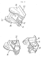
- the movable element 2 has in all embodiments, a box construction with two side cheeks 50, a lower flange 51 and optionally a top flange.
- the box construction is connected to the bearing 52 in connection, via which the movable element 2 is articulated pivotably about a horizontal axis on the implement.
- the side walls thus run substantially in the vertical direction.
- a tube 55 is provided which connects the side walls 50 of the box construction. Between the two side walls 50 tabs 57 are connected to the tube 55 to which the energy recovery hydraulic cylinder is articulated.
- the tube 55 is guided by recesses in the side cheeks 50, wherein outside of the side cheeks on the tube tabs 56 are provided for articulation of the working hydraulic cylinder.
- the tube can be made less massive, since it is less subject to bending by the support of the movable element on the energy recovery hydraulic cylinder.
- the lower flange 51 of the box construction is designed in several parts, wherein a first Untergurtblech 51 a and a second Untergurtblech 51 b encountered on the tube 55 and welded thereto.
- recesses 58 are provided in the region of the tube 55 through which the tabs 57 for storage of the energy recovery hydraulic cylinder through led and with which they are welded. This allows a better connection of the tabs 57th
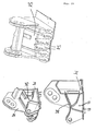
- a second embodiment of the linkage in which the tube 55 extends below the lower flange.
- the side cheeks 50 are pulled down below the lower flange in the region of the tube 55.
- the storage of the energy recovery hydraulic cylinder is in turn carried out on tabs 57 which are welded to the tube 55.
- the storage of the working cylinder takes place by means of a bolt 60, which is guided in the tube 55.
- a third embodiment of the invention articulation is shown in which castings 61 are provided, in which the bolt 60 is mounted to support the working cylinder.
- the bolt 60 extends in the interior of the tube 55, which has a larger diameter than the bolt, through the entire box construction.
- the tube 55 is guided by recesses in the side walls and welded there with these.
- the castings 61 are welded to the tube 55.
- the bolt 60 is mounted in the castings 61 and carries the bearing eyes 62 of the working cylinder.
- castings 61 for supporting the bolt 60 used are also welded to the castings 61.
- the arrangement of the tabs 57 for storage of the energy recovery hydraulic cylinder takes place in the third and fourth embodiment as in the first embodiment.
- two plates of the lower flange abut against the tube 55, and the tabs are on the tube 55 between the two side walls 50th welded and passed through recesses in one of the Untergurtbleche.
- a welded construction of two side walls 70 and a bottom plate 72 is provided, wherein the movable element is mounted on bearing points 71 on the side walls 70.
- the bottom plate 72 of the welded construction serves as slewing ring support of the superstructure.
- the working hydraulic cylinders are mounted on the side walls 70 and on tabs 74, which are arranged within the side walls 71.
- tabs 73 are provided between the slave cylinder bearings.
- the cross plate 75 is welded to a front edge with the bottom plate 72 and with its side edges with the side cheeks 70.
- a first embodiment is shown in which the tabs 73 are placed on the cross plate 75 for storage of the energy recovery hydraulic cylinder and welded to this and to the bottom plate 72.
- a second embodiment is shown in which the cross plate 75 has recesses through which the tabs 73 pass.
- the tabs 73 are thus welded with its rear part with the bottom plate 72 and extend along the bottom plate up to another transverse plate 76, with which they are also welded.
- the further transverse plate 76 extends substantially perpendicular to the bottom plate and also connects the side walls 70 with each other.
- the tabs 73 extend through the recess in the transverse plate 75 into the area of the center of the turntable.
- the connection to the further cross plate 76 reduces the bending moment, which is due to the storage the bottom plate 72 acts in the area of the slewing ring support. This results in a stable connection.
- the present invention provides a possibility of energy recovery via the gas compressed in the bottom region and in the hollow piston rod of the energy recovery hydraulic cylinder, which is as effective as it is cost effective. Furthermore, the present invention shows extremely stable ways of supporting the power cylinders and the energy recovery hydraulic cylinder, for which protection is required independently of the execution of the energy recovery hydraulic cylinder.
Landscapes
- Engineering & Computer Science (AREA)
- General Engineering & Computer Science (AREA)
- Mechanical Engineering (AREA)
- Mining & Mineral Resources (AREA)
- Civil Engineering (AREA)
- Structural Engineering (AREA)
- Actuator (AREA)
- Operation Control Of Excavators (AREA)
- Fluid-Pressure Circuits (AREA)
- Supply Devices, Intensifiers, Converters, And Telemotors (AREA)
Applications Claiming Priority (1)
| Application Number | Priority Date | Filing Date | Title |
|---|---|---|---|
| DE102008034582A DE102008034582A1 (de) | 2008-07-24 | 2008-07-24 | Arbeitsgerät |
Publications (3)
| Publication Number | Publication Date |
|---|---|
| EP2148014A2 true EP2148014A2 (fr) | 2010-01-27 |
| EP2148014A3 EP2148014A3 (fr) | 2016-06-22 |
| EP2148014B1 EP2148014B1 (fr) | 2021-12-29 |
Family
ID=41111140
Family Applications (1)
| Application Number | Title | Priority Date | Filing Date |
|---|---|---|---|
| EP09008879.0A Active EP2148014B1 (fr) | 2008-07-24 | 2009-07-07 | Appareil de travail |
Country Status (5)
| Country | Link |
|---|---|
| US (1) | US8418451B2 (fr) |
| EP (1) | EP2148014B1 (fr) |
| JP (1) | JP5683797B2 (fr) |
| KR (1) | KR101711645B1 (fr) |
| DE (1) | DE102008034582A1 (fr) |
Cited By (8)
| Publication number | Priority date | Publication date | Assignee | Title |
|---|---|---|---|---|
| EP2455553A1 (fr) * | 2010-11-17 | 2012-05-23 | Liebherr-Hydraulikbagger GmbH | Appareil de travail |
| EP2455552A1 (fr) * | 2010-11-17 | 2012-05-23 | Liebherr-Hydraulikbagger GmbH | Appareil de travail |
| EP2524997A1 (fr) * | 2011-05-18 | 2012-11-21 | Liebherr-Hydraulikbagger GmbH | Outil de travail, en particulier machine d'excavation ou machine de transvasement de matériel |
| CN102943496A (zh) * | 2012-12-03 | 2013-02-27 | 柳工常州挖掘机有限公司 | 挖掘机动臂势能循环利用系统 |
| CN106120915A (zh) * | 2016-08-24 | 2016-11-16 | 崔建波 | 挖掘机 |
| WO2017176897A1 (fr) * | 2016-04-06 | 2017-10-12 | Oshkosh Corporation | Ensemble d'actionneur double |
| WO2017220202A1 (fr) * | 2016-06-21 | 2017-12-28 | Liebherr-Components Kirchdorfgmbh | Procédé de fabrication d'une unité tige de piston et d'un arbre creux |
| CN108678394A (zh) * | 2018-03-30 | 2018-10-19 | 中建钢构有限公司 | 钢结构件安装装置以及钢结构件安装方法 |
Families Citing this family (29)
| Publication number | Priority date | Publication date | Assignee | Title |
|---|---|---|---|---|
| US8474255B2 (en) * | 2008-04-09 | 2013-07-02 | Sustainx, Inc. | Forming liquid sprays in compressed-gas energy storage systems for effective heat exchange |
| DE102010032415A1 (de) * | 2010-07-27 | 2012-02-02 | Hydac Technology Gmbh | Vorrichtung zur Rückgewinnung von Energie |
| EP2426271A3 (fr) * | 2010-09-07 | 2012-10-24 | Caterpillar Work Tools B. V. | Dispositif pour actionner un couvercle de contamination de connecteur de fluides |
| DE102010049750B3 (de) * | 2010-10-29 | 2012-01-26 | Montanhydraulik Gmbh | Rückfallpresse |
| DE102010051664A1 (de) * | 2010-11-17 | 2012-05-24 | Liebherr-Hydraulikbagger Gmbh | Arbeitsgerät |
| DE102010051651A1 (de) | 2010-11-17 | 2012-05-24 | Liebherr-Hydraulikbagger Gmbh | Arbeitsgerät |
| DE102010051663A1 (de) | 2010-11-17 | 2012-05-24 | Liebherr-Hydraulikbagger Gmbh | Arbeitsgerät |
| PE20141415A1 (es) * | 2011-03-21 | 2014-10-25 | Shuanglai Yang | Sistema de elevacion y metodo de elevacion para el brazo de la maquina de operacion y maquina de operacion |
| DE102011106672A1 (de) | 2011-07-06 | 2013-01-10 | Thomas Sauer | Hydraulikzylinder zur Energierückgewinnung |
| US9151018B2 (en) * | 2011-09-30 | 2015-10-06 | Caterpillar Inc. | Closed-loop hydraulic system having energy recovery |
| US10570930B2 (en) | 2011-10-10 | 2020-02-25 | Angus Peter Robson | Accumulator |
| US9790962B2 (en) * | 2011-10-10 | 2017-10-17 | Angus Peter Robson | Accumulator |
| DE102011119011A1 (de) | 2011-11-14 | 2013-05-16 | Hydac Technology Gmbh | Gaszylinder, insbesondere Hochdruck-Gaszylinder |
| CN102518606B8 (zh) * | 2011-12-12 | 2017-04-19 | 杨双来 | 用于作业机械的起重臂的升降系统和升降方法及作业机械 |
| ITMI20120206A1 (it) * | 2012-02-14 | 2013-08-15 | Cifa Spa | Segmento di un braccio articolato e braccio articolato comprendente detto segmento |
| WO2013165586A1 (fr) * | 2012-04-30 | 2013-11-07 | Eaton Corporation | Système d'actionnement combiné hydraulique/pneumatique comprenant un piston pneumatique interne |
| CN102720731A (zh) * | 2012-06-08 | 2012-10-10 | 山河智能装备股份有限公司 | 一种工作装置的节能系统 |
| WO2014017958A1 (fr) * | 2012-07-26 | 2014-01-30 | Volvo Construction Equipment Ab | Tringlerie équilibrée |
| DE102013006204A1 (de) * | 2013-04-04 | 2014-10-09 | Sennebogen Maschinenfabrik Gmbh | Betätigungseinrichtung und Arbeitsgerätschaft mit einer solchen Betätigungseinrichtung |
| US9441644B2 (en) | 2014-08-26 | 2016-09-13 | Ut-Battelle, Llc | Energy efficient fluid powered linear actuator with variable area |
| US9494168B2 (en) | 2014-08-26 | 2016-11-15 | Ut-Battelle, Llc | Energy efficient fluid powered linear actuator with variable area and concentric chambers |
| JP6601834B2 (ja) * | 2015-04-21 | 2019-11-06 | キャタピラー エス エー アール エル | 流体圧回路および作業機械 |
| DE102016002589A1 (de) * | 2016-03-03 | 2017-09-07 | Liebherr-Werk Ehingen Gmbh | Mobilkran |
| FR3070450A1 (fr) * | 2017-08-24 | 2019-03-01 | Societe Des Usines Quiri Et Cie | Dispositif de verin simple effet avec rappel par fluide compressible |
| TWI731259B (zh) * | 2018-08-28 | 2021-06-21 | 財團法人工業技術研究院 | 用於機械手臂的負載平衡裝置 |
| NO20200709A1 (no) * | 2019-06-17 | 2020-12-18 | Conrobotix As | Sylinder, hydraulisk system, anleggsmaskin og fremgangsmåte |
| US11400790B2 (en) * | 2020-01-30 | 2022-08-02 | Schaeffler Technologies AG & Co. KG | Concentric hydraulic ride height actuator for a motor vehicle |
| CN111577707A (zh) * | 2020-05-28 | 2020-08-25 | 浙江明思特建筑支护技术有限公司 | 一种随动自锁式液压系统 |
| US11668072B1 (en) * | 2022-10-26 | 2023-06-06 | Bourgault Industries Ltd. | Potential energy storage and control system for a hydraulically actuated element |
Citations (1)
| Publication number | Priority date | Publication date | Assignee | Title |
|---|---|---|---|---|
| DE102004032868A1 (de) | 2004-07-07 | 2006-02-09 | Liebherr-Hydraulikbagger Gmbh | Bagger und Maschine zum Materialumschlag |
Family Cites Families (32)
| Publication number | Priority date | Publication date | Assignee | Title |
|---|---|---|---|---|
| US2163982A (en) * | 1935-03-11 | 1939-06-27 | Mereier Jean | Fluid-operated jack |
| GB485617A (en) * | 1936-11-14 | 1938-05-16 | John Henry Onions | Improvements in or relating to jacks, more particularly for retractable undercarriages for aircraft |
| US2976845A (en) * | 1959-12-18 | 1961-03-28 | Modernair Corp | Pneumatic-hydraulic drive cylinder |
| GB1236384A (en) * | 1967-08-11 | 1971-06-23 | Plessey Co Ltd | Improvements in or relating to actuators having a hydraulic actuator ram |
| US3869861A (en) * | 1973-10-15 | 1975-03-11 | Hesston Corp | Combination hydraulic cylinder and accumulator |
| US4175907A (en) * | 1977-07-07 | 1979-11-27 | Caterpillar Tractor Co. | Shovel linkage |
| JPH063238B2 (ja) * | 1986-11-12 | 1994-01-12 | いすゞ自動車株式会社 | ハイドロニユ−マチツク・サスペンシヨン装置 |
| DE3839446A1 (de) * | 1987-11-28 | 1989-06-15 | Hemscheidt Maschf Hermann | Hydro-pneumatischer stoss- und schwingungsdaempfer mit innenrohr |
| JP2562645B2 (ja) | 1988-01-30 | 1996-12-11 | 株式会社小松製作所 | 油圧式掘削機のブームエネルギー再生装置 |
| US5042253A (en) * | 1989-05-15 | 1991-08-27 | Ishigame Machinery Co., Ltd. | Hydraulic-pneumatic cylinder device with annular flexible bag as interface |
| DD299906A7 (de) * | 1989-10-05 | 1992-05-14 | Schwermasch Nobas Veb | Arbeitsausrüstung für einen hydraulischen Universalbagger |
| EP0425885B1 (fr) * | 1989-10-28 | 1994-07-20 | HEMSCHEIDT FAHRWERKTECHNIK GmbH & Co. | Système à ressort hydropneumatique |
| JPH0890201A (ja) * | 1994-09-14 | 1996-04-09 | Toshiba Mach Co Ltd | ダイカストマシンの射出装置 |
| US5921604A (en) * | 1996-05-16 | 1999-07-13 | Applied Power Inc. | Hydraulic door operating system |
| US5971027A (en) * | 1996-07-01 | 1999-10-26 | Wisconsin Alumni Research Foundation | Accumulator for energy storage and delivery at multiple pressures |
| SE9700297D0 (sv) * | 1997-01-31 | 1997-01-31 | Lars Bruun | Anordning vid hydrauliskt manövrerade arbetsredskap |
| US5984618A (en) * | 1997-06-30 | 1999-11-16 | Caterpillar Inc. | Box boom loader mechanism |
| US6497059B1 (en) * | 1999-04-06 | 2002-12-24 | Edwin E. Downer, Jr. | Energy conservation system for earth-moving loading machines |
| US6481335B2 (en) * | 1999-12-23 | 2002-11-19 | Mark Y. Shteynberg | Hybrid actuator |
| JP2002226186A (ja) * | 2001-01-26 | 2002-08-14 | Oil Drive Kogyo Kk | 油圧ジャッキ |
| JP2002372009A (ja) * | 2001-06-15 | 2002-12-26 | Kayaba Engineering & Service Kk | 流体圧シリンダと制御回路 |
| JP2004092210A (ja) * | 2002-08-30 | 2004-03-25 | Komatsu Ltd | 作業機 |
| JP3929380B2 (ja) * | 2002-09-26 | 2007-06-13 | 株式会社小松製作所 | 作業機の位置エネルギ回収・再生装置 |
| JP2004116674A (ja) * | 2002-09-26 | 2004-04-15 | Komatsu Ltd | 作業機の位置エネルギ回収・再生装置 |
| JP4115918B2 (ja) * | 2003-10-28 | 2008-07-09 | 株式会社小松製作所 | 油圧シリンダ |
| US6918247B1 (en) * | 2003-11-19 | 2005-07-19 | Jack E Warner | Assisted hydraulic system for moving a structural member |
| US6892825B1 (en) * | 2004-03-09 | 2005-05-17 | Donald G. Hopson | Bulldozer rear blade mounting apparatus |
| US7104052B1 (en) * | 2005-03-15 | 2006-09-12 | Deere & Company | Hydraulic cylinder with integrated accumulator |
| US20070068754A1 (en) * | 2005-09-26 | 2007-03-29 | Furgala George W | Gas-biased hydraulic cylinder |
| RO122787B1 (ro) * | 2006-07-24 | 2010-01-29 | Sorin Dinu | Dispozitiv de recuperare a energiei din operaţia de coborâre a braţului unui utilaj |
| US7832130B2 (en) * | 2006-10-06 | 2010-11-16 | The Stanley Works | Multiple mounting bracket for a mobile processor attachment mounted on a hydraulic excavator |
| DE102007050350A1 (de) * | 2007-09-21 | 2009-04-02 | Thomas Sauer | Hydraulikzylinder mit Energiespeicher |
-
2008
- 2008-07-24 DE DE102008034582A patent/DE102008034582A1/de not_active Withdrawn
-
2009
- 2009-07-07 EP EP09008879.0A patent/EP2148014B1/fr active Active
- 2009-07-21 JP JP2009170084A patent/JP5683797B2/ja active Active
- 2009-07-21 KR KR1020090066445A patent/KR101711645B1/ko active IP Right Grant
- 2009-07-24 US US12/508,884 patent/US8418451B2/en active Active
Patent Citations (1)
| Publication number | Priority date | Publication date | Assignee | Title |
|---|---|---|---|---|
| DE102004032868A1 (de) | 2004-07-07 | 2006-02-09 | Liebherr-Hydraulikbagger Gmbh | Bagger und Maschine zum Materialumschlag |
Cited By (16)
| Publication number | Priority date | Publication date | Assignee | Title |
|---|---|---|---|---|
| EP2455553A1 (fr) * | 2010-11-17 | 2012-05-23 | Liebherr-Hydraulikbagger GmbH | Appareil de travail |
| EP2455552A1 (fr) * | 2010-11-17 | 2012-05-23 | Liebherr-Hydraulikbagger GmbH | Appareil de travail |
| US9127736B2 (en) | 2010-11-17 | 2015-09-08 | Liebherr-Hydraulikbagger Gmbh | Working device |
| EP2524997A1 (fr) * | 2011-05-18 | 2012-11-21 | Liebherr-Hydraulikbagger GmbH | Outil de travail, en particulier machine d'excavation ou machine de transvasement de matériel |
| CN102943496A (zh) * | 2012-12-03 | 2013-02-27 | 柳工常州挖掘机有限公司 | 挖掘机动臂势能循环利用系统 |
| US11225400B2 (en) | 2016-04-06 | 2022-01-18 | Oshkosh Corporation | Dual actuator assembly |
| WO2017176897A1 (fr) * | 2016-04-06 | 2017-10-12 | Oshkosh Corporation | Ensemble d'actionneur double |
| US10294086B2 (en) | 2016-04-06 | 2019-05-21 | Oshkosh Corporation | Dual actuator assembly |
| US10611611B2 (en) | 2016-04-06 | 2020-04-07 | Oshkosh Corporation | Dual actuator assembly |
| US11661319B2 (en) | 2016-04-06 | 2023-05-30 | Oshkosh Corporation | Dual actuator assembly |
| WO2017220202A1 (fr) * | 2016-06-21 | 2017-12-28 | Liebherr-Components Kirchdorfgmbh | Procédé de fabrication d'une unité tige de piston et d'un arbre creux |
| US11193511B2 (en) | 2016-06-21 | 2021-12-07 | Liebherr-Components Kirchdorf GmbH | Method for manufacturing a piston rod unit and a hollow shaft |
| AU2017280498B2 (en) * | 2016-06-21 | 2023-02-02 | Liebherr-Components Kirchdorf GmbH | Method for manufacturing a piston rod unit and a hollow shaft |
| US11841034B2 (en) | 2016-06-21 | 2023-12-12 | Liebherr-Components Kirchdorf GmbH | Method for manufacturing a piston rod unit and a hollow shaft |
| CN106120915A (zh) * | 2016-08-24 | 2016-11-16 | 崔建波 | 挖掘机 |
| CN108678394A (zh) * | 2018-03-30 | 2018-10-19 | 中建钢构有限公司 | 钢结构件安装装置以及钢结构件安装方法 |
Also Published As
| Publication number | Publication date |
|---|---|
| US8418451B2 (en) | 2013-04-16 |
| KR20100011917A (ko) | 2010-02-03 |
| JP5683797B2 (ja) | 2015-03-11 |
| KR101711645B1 (ko) | 2017-03-13 |
| DE102008034582A1 (de) | 2010-01-28 |
| EP2148014A3 (fr) | 2016-06-22 |
| JP2010032046A (ja) | 2010-02-12 |
| US20100018195A1 (en) | 2010-01-28 |
| EP2148014B1 (fr) | 2021-12-29 |
Similar Documents
| Publication | Publication Date | Title |
|---|---|---|
| EP2148014B1 (fr) | Appareil de travail | |
| EP2598771B1 (fr) | Dispositif pour la récupération d'énergie | |
| EP2238071B1 (fr) | Engin de travail mobile | |
| EP1438886B1 (fr) | Dispositif d'accouplement | |
| EP1813730B1 (fr) | Chargeur frontal et cabine pour tracteur | |
| DE102012006494B4 (de) | Fahrzeugkran mit entkoppelbarer Gegengewichtsanordnung | |
| EP2139804B1 (fr) | Mécanisme de réglage pourvu d'un treuil à câble | |
| EP1496009A1 (fr) | Suspension hydraulique | |
| EP0182091B1 (fr) | Elévateur de puissance pour un dispositif de levage | |
| DE3637709C2 (fr) | ||
| EP3159549B1 (fr) | Dispositif de recuperation d'energie hydraulique pour un engin de travail et engin de travail correspondant | |
| EP0789816B1 (fr) | Dispositif de recuperation d'energie | |
| EP1621682A2 (fr) | Appareil de transbordement. | |
| DE102008007917A1 (de) | Fahrbare Arbeitsmaschine | |
| EP2455554A2 (fr) | Appareil de travail | |
| EP3243735B1 (fr) | Dispositif compensatoire d'état de la mer | |
| EP2455553B1 (fr) | Appareil de travail | |
| DE69122933T2 (de) | Senkrechtausleger für Hublader | |
| EP2455552B1 (fr) | Appareil de travail | |
| WO2011154396A1 (fr) | Procédé de commande d'un organe de travail déplaçable hydrauliquement d'une machine de travail, et machine de travail correspondante | |
| DE10214915B4 (de) | Hinterachsverriegelung | |
| DE102011111251B4 (de) | Landmaschine | |
| DE3241604A1 (de) | Fahrzeug mit zwei relativ zueinander verschwenkbaren teilen | |
| DE102012217650B4 (de) | Schmiedemanipulator sowie Verfahren zum Betrieb eines Schmiedemanipulators | |
| DE4009979C2 (fr) |
Legal Events
| Date | Code | Title | Description |
|---|---|---|---|
| PUAI | Public reference made under article 153(3) epc to a published international application that has entered the european phase |
Free format text: ORIGINAL CODE: 0009012 |
|
| AK | Designated contracting states |
Kind code of ref document: A2 Designated state(s): AT BE BG CH CY CZ DE DK EE ES FI FR GB GR HR HU IE IS IT LI LT LU LV MC MK MT NL NO PL PT RO SE SI SK SM TR |
|
| AX | Request for extension of the european patent |
Extension state: AL BA RS |
|
| RIC1 | Information provided on ipc code assigned before grant |
Ipc: E02F 9/22 20060101AFI20160128BHEP |
|
| PUAL | Search report despatched |
Free format text: ORIGINAL CODE: 0009013 |
|
| AK | Designated contracting states |
Kind code of ref document: A3 Designated state(s): AT BE BG CH CY CZ DE DK EE ES FI FR GB GR HR HU IE IS IT LI LT LU LV MC MK MT NL NO PL PT RO SE SI SK SM TR |
|
| AX | Request for extension of the european patent |
Extension state: AL BA RS |
|
| RIC1 | Information provided on ipc code assigned before grant |
Ipc: E02F 9/22 20060101AFI20160518BHEP Ipc: E02F 3/38 20060101ALI20160518BHEP |
|
| STAA | Information on the status of an ep patent application or granted ep patent |
Free format text: STATUS: REQUEST FOR EXAMINATION WAS MADE |
|
| 17P | Request for examination filed |
Effective date: 20161215 |
|
| STAA | Information on the status of an ep patent application or granted ep patent |
Free format text: STATUS: EXAMINATION IS IN PROGRESS |
|
| STAA | Information on the status of an ep patent application or granted ep patent |
Free format text: STATUS: EXAMINATION IS IN PROGRESS |
|
| 17Q | First examination report despatched |
Effective date: 20201014 |
|
| GRAP | Despatch of communication of intention to grant a patent |
Free format text: ORIGINAL CODE: EPIDOSNIGR1 |
|
| STAA | Information on the status of an ep patent application or granted ep patent |
Free format text: STATUS: GRANT OF PATENT IS INTENDED |
|
| INTG | Intention to grant announced |
Effective date: 20210723 |
|
| GRAS | Grant fee paid |
Free format text: ORIGINAL CODE: EPIDOSNIGR3 |
|
| GRAA | (expected) grant |
Free format text: ORIGINAL CODE: 0009210 |
|
| STAA | Information on the status of an ep patent application or granted ep patent |
Free format text: STATUS: THE PATENT HAS BEEN GRANTED |
|
| AK | Designated contracting states |
Kind code of ref document: B1 Designated state(s): AT BE BG CH CY CZ DE DK EE ES FI FR GB GR HR HU IE IS IT LI LT LU LV MC MK MT NL NO PL PT RO SE SI SK SM TR |
|
| REG | Reference to a national code |
Ref country code: GB Ref legal event code: FG4D Free format text: NOT ENGLISH |
|
| REG | Reference to a national code |
Ref country code: CH Ref legal event code: EP |
|
| REG | Reference to a national code |
Ref country code: FI Ref legal event code: FGE |
|
| REG | Reference to a national code |
Ref country code: AT Ref legal event code: REF Ref document number: 1458751 Country of ref document: AT Kind code of ref document: T Effective date: 20220115 |
|
| REG | Reference to a national code |
Ref country code: IE Ref legal event code: FG4D Free format text: LANGUAGE OF EP DOCUMENT: GERMAN |
|
| REG | Reference to a national code |
Ref country code: DE Ref legal event code: R096 Ref document number: 502009016413 Country of ref document: DE |
|
| REG | Reference to a national code |
Ref country code: NL Ref legal event code: FP |
|
| REG | Reference to a national code |
Ref country code: LT Ref legal event code: MG9D |
|
| REG | Reference to a national code |
Ref country code: SE Ref legal event code: TRGR |
|
| PG25 | Lapsed in a contracting state [announced via postgrant information from national office to epo] |
Ref country code: LT Free format text: LAPSE BECAUSE OF FAILURE TO SUBMIT A TRANSLATION OF THE DESCRIPTION OR TO PAY THE FEE WITHIN THE PRESCRIBED TIME-LIMIT Effective date: 20211229 Ref country code: BG Free format text: LAPSE BECAUSE OF FAILURE TO SUBMIT A TRANSLATION OF THE DESCRIPTION OR TO PAY THE FEE WITHIN THE PRESCRIBED TIME-LIMIT Effective date: 20220329 |
|
| PG25 | Lapsed in a contracting state [announced via postgrant information from national office to epo] |
Ref country code: NO Free format text: LAPSE BECAUSE OF FAILURE TO SUBMIT A TRANSLATION OF THE DESCRIPTION OR TO PAY THE FEE WITHIN THE PRESCRIBED TIME-LIMIT Effective date: 20220329 Ref country code: LV Free format text: LAPSE BECAUSE OF FAILURE TO SUBMIT A TRANSLATION OF THE DESCRIPTION OR TO PAY THE FEE WITHIN THE PRESCRIBED TIME-LIMIT Effective date: 20211229 Ref country code: HR Free format text: LAPSE BECAUSE OF FAILURE TO SUBMIT A TRANSLATION OF THE DESCRIPTION OR TO PAY THE FEE WITHIN THE PRESCRIBED TIME-LIMIT Effective date: 20211229 Ref country code: GR Free format text: LAPSE BECAUSE OF FAILURE TO SUBMIT A TRANSLATION OF THE DESCRIPTION OR TO PAY THE FEE WITHIN THE PRESCRIBED TIME-LIMIT Effective date: 20220330 |
|
| PG25 | Lapsed in a contracting state [announced via postgrant information from national office to epo] |
Ref country code: SM Free format text: LAPSE BECAUSE OF FAILURE TO SUBMIT A TRANSLATION OF THE DESCRIPTION OR TO PAY THE FEE WITHIN THE PRESCRIBED TIME-LIMIT Effective date: 20211229 Ref country code: SK Free format text: LAPSE BECAUSE OF FAILURE TO SUBMIT A TRANSLATION OF THE DESCRIPTION OR TO PAY THE FEE WITHIN THE PRESCRIBED TIME-LIMIT Effective date: 20211229 Ref country code: RO Free format text: LAPSE BECAUSE OF FAILURE TO SUBMIT A TRANSLATION OF THE DESCRIPTION OR TO PAY THE FEE WITHIN THE PRESCRIBED TIME-LIMIT Effective date: 20211229 Ref country code: PT Free format text: LAPSE BECAUSE OF FAILURE TO SUBMIT A TRANSLATION OF THE DESCRIPTION OR TO PAY THE FEE WITHIN THE PRESCRIBED TIME-LIMIT Effective date: 20220429 Ref country code: ES Free format text: LAPSE BECAUSE OF FAILURE TO SUBMIT A TRANSLATION OF THE DESCRIPTION OR TO PAY THE FEE WITHIN THE PRESCRIBED TIME-LIMIT Effective date: 20211229 Ref country code: EE Free format text: LAPSE BECAUSE OF FAILURE TO SUBMIT A TRANSLATION OF THE DESCRIPTION OR TO PAY THE FEE WITHIN THE PRESCRIBED TIME-LIMIT Effective date: 20211229 Ref country code: CZ Free format text: LAPSE BECAUSE OF FAILURE TO SUBMIT A TRANSLATION OF THE DESCRIPTION OR TO PAY THE FEE WITHIN THE PRESCRIBED TIME-LIMIT Effective date: 20211229 |
|
| PG25 | Lapsed in a contracting state [announced via postgrant information from national office to epo] |
Ref country code: PL Free format text: LAPSE BECAUSE OF FAILURE TO SUBMIT A TRANSLATION OF THE DESCRIPTION OR TO PAY THE FEE WITHIN THE PRESCRIBED TIME-LIMIT Effective date: 20211229 |
|
| PG25 | Lapsed in a contracting state [announced via postgrant information from national office to epo] |
Ref country code: IS Free format text: LAPSE BECAUSE OF FAILURE TO SUBMIT A TRANSLATION OF THE DESCRIPTION OR TO PAY THE FEE WITHIN THE PRESCRIBED TIME-LIMIT Effective date: 20220429 |
|
| REG | Reference to a national code |
Ref country code: DE Ref legal event code: R097 Ref document number: 502009016413 Country of ref document: DE |
|
| PG25 | Lapsed in a contracting state [announced via postgrant information from national office to epo] |
Ref country code: DK Free format text: LAPSE BECAUSE OF FAILURE TO SUBMIT A TRANSLATION OF THE DESCRIPTION OR TO PAY THE FEE WITHIN THE PRESCRIBED TIME-LIMIT Effective date: 20211229 |
|
| PLBE | No opposition filed within time limit |
Free format text: ORIGINAL CODE: 0009261 |
|
| STAA | Information on the status of an ep patent application or granted ep patent |
Free format text: STATUS: NO OPPOSITION FILED WITHIN TIME LIMIT |
|
| 26N | No opposition filed |
Effective date: 20220930 |
|
| PG25 | Lapsed in a contracting state [announced via postgrant information from national office to epo] |
Ref country code: SI Free format text: LAPSE BECAUSE OF FAILURE TO SUBMIT A TRANSLATION OF THE DESCRIPTION OR TO PAY THE FEE WITHIN THE PRESCRIBED TIME-LIMIT Effective date: 20211229 Ref country code: MC Free format text: LAPSE BECAUSE OF FAILURE TO SUBMIT A TRANSLATION OF THE DESCRIPTION OR TO PAY THE FEE WITHIN THE PRESCRIBED TIME-LIMIT Effective date: 20211229 |
|
| REG | Reference to a national code |
Ref country code: CH Ref legal event code: PL |
|
| PG25 | Lapsed in a contracting state [announced via postgrant information from national office to epo] |
Ref country code: LU Free format text: LAPSE BECAUSE OF NON-PAYMENT OF DUE FEES Effective date: 20220707 Ref country code: LI Free format text: LAPSE BECAUSE OF NON-PAYMENT OF DUE FEES Effective date: 20220731 Ref country code: CH Free format text: LAPSE BECAUSE OF NON-PAYMENT OF DUE FEES Effective date: 20220731 |
|
| P01 | Opt-out of the competence of the unified patent court (upc) registered |
Effective date: 20230607 |
|
| PG25 | Lapsed in a contracting state [announced via postgrant information from national office to epo] |
Ref country code: IE Free format text: LAPSE BECAUSE OF NON-PAYMENT OF DUE FEES Effective date: 20220707 |
|
| PGFP | Annual fee paid to national office [announced via postgrant information from national office to epo] |
Ref country code: NL Payment date: 20230724 Year of fee payment: 15 |
|
| REG | Reference to a national code |
Ref country code: AT Ref legal event code: MM01 Ref document number: 1458751 Country of ref document: AT Kind code of ref document: T Effective date: 20220707 |
|
| PG25 | Lapsed in a contracting state [announced via postgrant information from national office to epo] |
Ref country code: AT Free format text: LAPSE BECAUSE OF NON-PAYMENT OF DUE FEES Effective date: 20220707 |
|
| PGFP | Annual fee paid to national office [announced via postgrant information from national office to epo] |
Ref country code: IT Payment date: 20230727 Year of fee payment: 15 Ref country code: GB Payment date: 20230720 Year of fee payment: 15 Ref country code: FI Payment date: 20230721 Year of fee payment: 15 |
|
| PGFP | Annual fee paid to national office [announced via postgrant information from national office to epo] |
Ref country code: SE Payment date: 20230721 Year of fee payment: 15 Ref country code: FR Payment date: 20230721 Year of fee payment: 15 Ref country code: DE Payment date: 20230724 Year of fee payment: 15 Ref country code: BE Payment date: 20230720 Year of fee payment: 15 |
|
| PG25 | Lapsed in a contracting state [announced via postgrant information from national office to epo] |
Ref country code: HU Free format text: LAPSE BECAUSE OF FAILURE TO SUBMIT A TRANSLATION OF THE DESCRIPTION OR TO PAY THE FEE WITHIN THE PRESCRIBED TIME-LIMIT; INVALID AB INITIO Effective date: 20090707 |
|
| PG25 | Lapsed in a contracting state [announced via postgrant information from national office to epo] |
Ref country code: MK Free format text: LAPSE BECAUSE OF FAILURE TO SUBMIT A TRANSLATION OF THE DESCRIPTION OR TO PAY THE FEE WITHIN THE PRESCRIBED TIME-LIMIT Effective date: 20211229 Ref country code: CY Free format text: LAPSE BECAUSE OF FAILURE TO SUBMIT A TRANSLATION OF THE DESCRIPTION OR TO PAY THE FEE WITHIN THE PRESCRIBED TIME-LIMIT Effective date: 20211229 |