EP1438886B1 - Dispositif d'accouplement - Google Patents
Dispositif d'accouplement Download PDFInfo
- Publication number
- EP1438886B1 EP1438886B1 EP04000770A EP04000770A EP1438886B1 EP 1438886 B1 EP1438886 B1 EP 1438886B1 EP 04000770 A EP04000770 A EP 04000770A EP 04000770 A EP04000770 A EP 04000770A EP 1438886 B1 EP1438886 B1 EP 1438886B1
- Authority
- EP
- European Patent Office
- Prior art keywords
- activation
- coupling device
- hydraulic
- actuator
- coupled
- Prior art date
- Legal status (The legal status is an assumption and is not a legal conclusion. Google has not performed a legal analysis and makes no representation as to the accuracy of the status listed.)
- Expired - Lifetime
Links
- 230000008878 coupling Effects 0.000 title claims abstract description 26
- 238000010168 coupling process Methods 0.000 title claims abstract description 26
- 238000005859 coupling reaction Methods 0.000 title claims abstract description 26
- 230000033001 locomotion Effects 0.000 claims abstract description 9
- 239000012530 fluid Substances 0.000 claims description 5
- 230000004913 activation Effects 0.000 claims 9
- 230000000903 blocking effect Effects 0.000 claims 1
- 230000004048 modification Effects 0.000 description 5
- 238000012986 modification Methods 0.000 description 5
- 238000006073 displacement reaction Methods 0.000 description 3
- 239000007788 liquid Substances 0.000 description 3
- 230000000712 assembly Effects 0.000 description 1
- 238000000429 assembly Methods 0.000 description 1
- 230000000052 comparative effect Effects 0.000 description 1
- 230000001419 dependent effect Effects 0.000 description 1
- 238000011161 development Methods 0.000 description 1
- 230000018109 developmental process Effects 0.000 description 1
- 239000000725 suspension Substances 0.000 description 1
Images


Classifications
-
- A—HUMAN NECESSITIES
- A01—AGRICULTURE; FORESTRY; ANIMAL HUSBANDRY; HUNTING; TRAPPING; FISHING
- A01B—SOIL WORKING IN AGRICULTURE OR FORESTRY; PARTS, DETAILS, OR ACCESSORIES OF AGRICULTURAL MACHINES OR IMPLEMENTS, IN GENERAL
- A01B63/00—Lifting or adjusting devices or arrangements for agricultural machines or implements
- A01B63/02—Lifting or adjusting devices or arrangements for agricultural machines or implements for implements mounted on tractors
- A01B63/10—Lifting or adjusting devices or arrangements for agricultural machines or implements for implements mounted on tractors operated by hydraulic or pneumatic means
- A01B63/1006—Lifting or adjusting devices or arrangements for agricultural machines or implements for implements mounted on tractors operated by hydraulic or pneumatic means the hydraulic or pneumatic means structurally belonging to the tractor
Definitions
- the invention relates to a coupling device according to the preamble of claim 1, in particular a three-point implement mounting for an industrial or agricultural utility vehicle, such as a tractor.
- a variety of different implements are compatible with conventional coupling devices (device attachments, hitch systems), especially with conventional three-point device attachments.
- Many implements such as mowers or Mähaufhneer, snowploughs and so on, in addition to the height control need a floating position or compensation for tilting, turning or pivoting transversely to the commercial vehicle longitudinal axis and / or suspension to ensure satisfactory functionality and to prevent damage.
- a compensating movement is not available in conventional three-point equipment and must be provided by the implement.
- the object underlying the invention is seen to provide a coupling device of the type mentioned, by which the above problems are overcome.
- a coupling device is to be specified and developed, which provides a compensating movement.
- the coupling device according to the invention thus provides a compensating movement for a work implement which can be coupled to a vehicle, wherein existing conventional coupling devices, in particular three-point implement attachments, can also be upgraded with few modifications.
- the usually provided lifting struts on hydraulic cylinders which are either coupled to a respective hydraulic accumulator or which common to the same or a common hydraulic accumulator.
- the coupling device according to the invention is particularly suitable for implements that work a large area. With her predeterminable biasing forces can be transferred to a working device, so that a predeterminable proportion of weight of a working device is worn or balanced on the lower link to exert or transmit a predetermined or desired pressure on the ground during operation of the implement.
- a lateral weight compensation can be achieved, since different hydraulic accumulator settings can be used.
- Fig. 1 shows a running in the form of a three-point device structure 10 coupling device for a tractor, as is known in the prior art.
- the three-point implement assembly 10 may be mounted on either the front or rear of a vehicle.
- the three-point implement assembly 10 includes on the right and left sides arms or lower links 12, 14, which for vertical rotation about a horizontal and transverse axis are fixed, which is defined by a mounted on the frame 18 of the host vehicle and transverse shaft 16.
- a third arm or a top link 20 has a length-adjustable turnbuckle or a lifting spindle and comprises one end which is connected rotatably about the bolt 22 arranged at a fork-shaped end of a propeller shaft fork 24.
- the other end of the propeller shaft 24 is disposed for vertical rotation about a horizontally and transversely disposed bolt 26, the bolt 26 is disposed on a bracket 28 which at a central location above and between the lower links 12, 14 screwed to the vehicle frame 18 is.
- a horizontally and transversely oriented lift shaft 30 is disposed for rotation within a support member 32 which is secured to the vehicle frame 18 at a location substantially vertically above the shaft 16 of the lower links 12, 14 ,
- a respective lifting arm 34 and 36 is mounted.
- Two lift rods 38, 40 include upper ends which are rotatably coupled via horizontally and transversely disposed bolts 42, 44 to the corresponding free end on the lift arms 34, 36.
- the lifting struts 38, 40 have lower ends, which are rotatably coupled via horizontally and transversely arranged bolts 46, 48 to fork pieces 50, 52, wherein the fork pieces 50, 52 fork-shaped lower ends, which via the horizontally and transversely disposed pivot pin 54 , 56 are coupled in a spreading arrangement to the lower links 12, 14, respectively.
- Right and left lift cylinders 58, 60 each include an upper end which is rotatably coupled to the respective lift arms 34, 36 via the bolts 62, 64, respectively.
- the lifting cylinders 58, 60 include in each case a lower end, which in each case is rotatably coupled to the vehicle frame 18 via the bolts 66, 68.
- FIG. 2 shows a running in the form of a three-point device structure 70 inventive coupling device, wherein the same or similar components or assemblies of the coupling device from FIG. 1 are identified with the same reference numerals.
- the three-point device structure 70 differs from the three-point device structure 10 in particular in that instead of the in FIG. 1 shown lifting struts 38, 40 hydraulically actuated actuators 72, 74 are provided.
- the hydraulically actuable actuator 72 comprises a piston rod 76, which has at its lower end a U-bracket, which is coupled by means of the bolt 54 on the lower link 12.
- the hydraulically actuatable actuator 72 includes a cylinder 78 having an upper end disposed between opposed handles of a forked end of the right lift arm 34 and coupled thereto via the pin 42. Accordingly, the actuator 74 has a piston rod 80 which includes a lower end defined by a U-bracket and which is coupled to the lower link 14 via the pivot pin 56. The actuator 74 includes a cylinder 82 having an upper end disposed between opposing handles of a forked end of the lift arm 36 and coupled thereto via the bolt 44.
- FIG. 3 shows a first embodiment of a drive circuit 84, which has a right and a left hydraulic accumulator or hydraulic accumulator 86, 88, which are respectively coupled to the piston rod chamber of the hydraulic cylinders 78, 82 via the respective branches 90, 92, when a supply line 94 is coupled to a supply pump 96, the supply pump 96 having an inlet coupled to a sump or tank 98.
- a left and a right, only schematically indicated control valve 100, 102 is respectively arranged in the branches 90, 92 between the pump 96 and the corresponding hydraulic accumulator 86, 88.
- FIG. 4 shows in a second embodiment, a drive circuit 104.
- the drive circuit 104 is a simplified embodiment of the drive circuit 84 from FIG. 3 , wherein only one hydraulic accumulator 106 and one branch line 108 is provided.
- the branch line 108 is coupled to the supply line 94 and at its opposite ends to the piston rod space of the respective hydraulically actuatable actuator 72, 74.
- the control circuit 104 further includes a merely schematically indicated control valve 110, which is arranged in the supply line 94 between the pump 96 and the branch line 108.
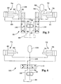
- FIG. 5 shows in a third embodiment a An horratursburg 8 for controlling the hydraulic actuators 72, 74.
- the An horrniklauf 85 includes a right hydraulic accumulator 86, which is connected to the piston rod chamber of the actuator 72 via a supply / return line 90. Furthermore, the An horrniklauf 85 includes a left hydraulic accumulator 88 which is connected to the piston rod chamber of the actuator 74 via a supply / return line 92.
- a right supply / return line 91 is connected to the piston chamber of the actuator 72, another left supply / return line 93 is connected to the piston chamber of the actuator 74.
- a pressurized fluid supply line 94 is connected to the outlet of the supply pump 96, with the supply pump 96 having an inlet coupled to a sump or tank 98.
- a right 4/4 way control valve 100 includes a set of supply / return line connections, which are respectively connected to the supply / return lines 90, 91, and includes a supply port and a return line port, each having a first branch Supply line 94 and connected to the sump 98 extending return line 97.
- a left 4/4-way control valve 102 is provided which has a set of supply / return line connections, which are connected to the supply / return lines 92, 93, and which has a supply connection and a return connection, which with a second branch of the supply line 94 and connected to the sump 98 extending return line 99.
- FIG. 6 shows in a fourth embodiment, a drive circuit 105.
- the drive circuit 105 is a simplification of the Anêtniklaufs 85 in that only one hydraulic accumulator 106 and only one control valve 110 is provided, which is designed in the form of a 4/3-way control valve, which compared to the valves 100 and 102 has a function less.
- the hydraulic accumulator 106 is connected to a branched supply / return line 108, which is arranged between a supply / return line connection of the control valve 110 and the piston rod chambers of the actuators 72, 74.
- the Supply line 94 is disposed between the outlet of supply pump 96 and a supply line port of valve 110, return line 99 is disposed between sump 98 and a return line port of valve 110.
- the three-point device structure 70 is connected to a work implement such as a large-area mower or the like, and that the drive circuit 85 is connected in accordance with FIG FIG. 5 is used.
- the servovalve not shown in the figures, is actuated to drive the lift cylinders 58, 60 to lower the implement and place the actuators 72, 74 in a compensating motion condition.
- the hitherto in a locked position - which corresponds to the upper valve position of the control valves 100, 102 - located control valves 100, 102 are each in a in the FIG. 5 shown working position.
- the inflow and outflow of the liquid flow of the piston rod space of the actuators 72, 74 is then prevented, wherein a lifting force is given, which is determined by the pressure in the hydraulic accumulators 86, 88 and which serves to compensate or for partially receiving the weight of the working device ,
- the pump 96 could - especially in drive circuits according to the FIGS. 3 to 6 be executed for example in the form of a variable displacement pump, wherein the variable displacement is adjusted so that the flow rate of the pump 96 is then almost zero when the control valves 100, 102 prevent fluid flow to the actuators 72, 74.
- a fixed displacement pump could also be used, but in this case the control valves 100, 102 would have to be replaced by valves which provide backflow to the sump 98 when the control valves are in a position in which the fluid flow to the actuators 72, 74 is prevented.
- the intended or desired pressure which is used by the hydraulic accumulators 86, 88, be dimensioned such that only a small proportion by weight of the working device acts during operation on the ground. If the weight distribution of the implement from one side to the other - especially with respect to the vehicle transverse axis - is not balanced, the hydraulic accumulators 86, 88 are set at different pressures, so that during operation, a compensation of the pressure acting on the ground pressure from one to the other side of the implement is achieved.
- ripples in the machined surface assist the work implement, usually in the form of cracks or the like, so that the implement follows the contour of the ground, liquid being transferred from the piston chambers of the cylinders 78, 82 to the sump 98, if any Pistons 76, 80 are deflected upward, and wherein liquid is moved into the piston chambers of the cylinder 78, 82, when the piston rods 76, 80 are deflected downwards.
- the degree of lifting force or compensating weight which is caused by the hydraulic accumulators 88, 86, can be increased by the valves 100, 102 from the working position shown in the figure - even independently - by an upward position be spent, in which the piston rod chamber with the supply pump 96 and the piston chamber with the sump 98 are connected.
- the degree of lifting force provided by the hydraulic accumulators 88, 86 can be achieved by moving the valves 100, 102 to their uppermost position, in which the piston rod spaces of the actuators 72, 78 with the sump 98 and in which the piston chambers are connected to the supply pump 96.
- valves 100, 102 are moved to their lowermost position in which fluid flow to and from the cylinders 78, 82 is prevented.
- the operation of the drive circuit 105 is basically the same as that of the drive circuit 85, but here only one hydraulic accumulator 106 is used, so that no lateral compensation for differences in weight of the implement of the opposite sides is provided with respect to the central longitudinal axis of the implement.
- the control valve 110 does not include a disabling function.
- the cylinders of the actuators 72, 74 are pressurized so that a lifting movement of the lifting arms 34, 36 is achieved, whereby the lower links 12, 14 are raised by means of the actuators 72, 74, if it should be desired Lift implement for transport.
Landscapes
- Life Sciences & Earth Sciences (AREA)
- Engineering & Computer Science (AREA)
- Mechanical Engineering (AREA)
- Soil Sciences (AREA)
- Environmental Sciences (AREA)
- Lifting Devices For Agricultural Implements (AREA)
- Fluid-Pressure Circuits (AREA)
- Seal Device For Vehicle (AREA)
- Physical Deposition Of Substances That Are Components Of Semiconductor Devices (AREA)
- Control Of Motors That Do Not Use Commutators (AREA)
- Agricultural Machines (AREA)
- Body Structure For Vehicles (AREA)
Claims (10)
- Dispositif d'accouplement, notamment une fixation d'appareil en trois points, pour un véhicule utilitaire agricole ou industriel, comprenant un cadre (18), avec deux bras inférieurs (12, 14), qui sont montés sur le cadre (18) de manière à tourner/pivoter essentiellement dans la direction verticale autour d'un premier axe disposé horizontalement, avec un arbre de levage (30) qui est monté sur le cadre (18) pour tourner - de préférence essentiellement dans la direction verticale - autour d'un deuxième axe disposé horizontalement, le deuxième axe étant disposé dans la direction verticale à distance du premier axe, avec deux bras de levage (34, 36), qui sont connectés à l'arbre de levage (30) dans la direction transversale en des points différents, avec deux renforts de levage (38, 40), qui peuvent être couplés à chaque fois par leur extrémité supérieure de manière rotative aux bras de levage correspondants (34, 36) et par leur extrémité inférieure à chaque fois aux bras inférieurs correspondants (12, 14), et avec un dispositif de levage qui est prévu entre le cadre (18) et l'arbre de levage (30) pour soulever et abaisser de manière sélective les bras inférieurs (12, 14) par une rotation sélectionnée de l'arbre de levage (30), les renforts de levage présentant des actionneurs hydrauliques pouvant être sortis et rentrés (72, 74), caractérisé en ce qu'il est prévu un circuit de commande (84, 85, 104, 105) qui est couplé aux actionneurs hydrauliques (72, 74) et qui présente un agencement d'accumulateurs hydrauliques (86, 88, 106), qui est réalisé pour s'opposer à une sortie de l'actionneur hydraulique (72, 74) et donc pour s'opposer à un déplacement vers le bas des bras inférieurs (12, 14).
- Dispositif d'accouplement selon la revendication 1, caractérisé en ce que l'agencement d'accumulateurs hydrauliques (86, 88 ; 106) présente au moins un accumulateur hydraulique (86, 88 ; 106).
- Dispositif d'accouplement selon la revendication 1 ou 2, caractérisé en ce que l'agencement d'accumulateurs hydrauliques (86, 88 ; 106) peut être couplé à l'espace de tige de piston de chaque actionneur (72, 74) et en ce que l'on peut obtenir avec l'agencement d'accumulateurs hydrauliques (86, 88 ; 106) de préférence un équilibrage du poids d'un appareil de travail porté par les bras inférieurs.
- Dispositif d'accouplement selon la revendication 2, caractérisé en ce que le circuit de commande (84, 85) présente un deuxième accumulateur hydraulique (88), en ce que de préférence le premier accumulateur hydraulique (86) ne peut être couplé qu'au premier actionneur (72) et en ce que de préférence le deuxième accumulateur hydraulique (88) ne peut être couplé qu'au deuxième actionneur (74).
- Dispositif d'accouplement selon l'une quelconque des revendications précédentes, caractérisé en ce que le circuit de commande (84, 85) présente une source de liquide sous pression (96) ainsi que des première et deuxième soupapes de commande (100, 102), les soupapes de commande (100, 102) pouvant être couplées à la source de liquide sous pression (96) et par conséquent au premier et au deuxième actionneur hydraulique (72, 74).
- Dispositif d'accouplement selon l'une quelconque des revendications précédentes, caractérisé en ce qu'un élément de connexion (20) est prévu, lequel est monté à rotation sur le cadre (18) dans une position centrale au-dessus des bras inférieurs (12, 14).
- Dispositif d'accouplement selon l'une quelconque des revendications précédentes, caractérisé en ce que le circuit de commande (84, 85 ; 104, 105) présente une source de liquide sous pression (96), un puisard (98), et une unité de soupape de commande (100, 102 ; 110), l'unité de soupape de commande (100, 102 ; 110) pouvant être couplée à la source de liquide sous pression (96), au puisard (98) et à l'agencement d'accumulateurs hydrauliques (86, 88 ; 106), et un état fonctionnel pouvant être créé avec l'unité de soupape de commande (100, 102 ; 110), dans lequel l'agencement d'accumulateurs hydrauliques (86, 88 ; 106) peut être isolé du puisard (98) et de la source de liquide sous pression (96) et dans lequel les espaces de piston des actionneurs (72, 74) peuvent être connectés au puisard (98).
- Dispositif d'accouplement selon l'une quelconque des revendications précédentes, caractérisé en ce qu'un état fonctionnel peut être créé avec l'unité de soupape de commande (100, 102 ; 110), dans lequel un état de chargement ou de déchargement est présent, et dans lequel la pression dans l'agencement d'accumulateurs hydrauliques (86, 88 ; 106) peut être augmentée ou réduite.
- Dispositif d'accouplement selon l'une quelconque des revendications précédentes, caractérisé en ce qu'un état fonctionnel peut être créé avec l'unité de soupape de commande (86, 88) lequel présente une fonction de blocage et dans lequel un flux de liquide vers et depuis les actionneurs hydrauliques (72, 74) peut être empêché.
- Dispositif d'accouplement selon l'une quelconque des revendications précédentes, caractérisé en ce que l'unité de soupape de commande présente des soupapes de commande (100, 102) qui peuvent être à chaque fois couplées à la source de liquide sous pression (96) et au puisard (98), une soupape de commande (100) pouvant être couplée à un accumulateur hydraulique (86) et au premier actionneur (72), et une autre soupape de commande (102) pouvant être couplée à un autre accumulateur hydraulique (88) et au deuxième actionneur (74).
Applications Claiming Priority (4)
| Application Number | Priority Date | Filing Date | Title |
|---|---|---|---|
| US10/346,881 US20040140109A1 (en) | 2003-01-16 | 2003-01-16 | Three-point hitch having flotation |
| US346881 | 2003-01-16 | ||
| US757889 | 2004-01-14 | ||
| US10/757,889 US6830110B2 (en) | 2003-01-16 | 2004-01-14 | Three-point hitch having flotation |
Publications (2)
| Publication Number | Publication Date |
|---|---|
| EP1438886A1 EP1438886A1 (fr) | 2004-07-21 |
| EP1438886B1 true EP1438886B1 (fr) | 2010-04-21 |
Family
ID=32599695
Family Applications (1)
| Application Number | Title | Priority Date | Filing Date |
|---|---|---|---|
| EP04000770A Expired - Lifetime EP1438886B1 (fr) | 2003-01-16 | 2004-01-15 | Dispositif d'accouplement |
Country Status (5)
| Country | Link |
|---|---|
| US (1) | US6830110B2 (fr) |
| EP (1) | EP1438886B1 (fr) |
| AT (1) | ATE464781T1 (fr) |
| CA (1) | CA2455185C (fr) |
| DE (1) | DE502004011060D1 (fr) |
Families Citing this family (28)
| Publication number | Priority date | Publication date | Assignee | Title |
|---|---|---|---|---|
| FR2857559B1 (fr) * | 2003-07-18 | 2006-08-18 | Kuhn Sa | Faucheuse agricole comportant un dispositif ameliore pour la mise en position de manoeuvre |
| DE10342403A1 (de) * | 2003-09-13 | 2005-04-07 | Deere & Company, Moline | Vorrichtung zur Kopplung eines Arbeitsgeräts an ein Arbeitsfahrzeug |
| US7686097B2 (en) * | 2005-08-31 | 2010-03-30 | Cnh America Llc | Three point hitch frame, draft arm and rear counterweight design |
| US7721813B2 (en) * | 2006-08-29 | 2010-05-25 | Cnh America Llc | Implement/hitch draft control using hitch cylinder pressure as load feedback |
| US7690450B2 (en) * | 2006-09-12 | 2010-04-06 | Parker-Hannifin Corporation | System for operating a hydraulically actuated device |
| US7938206B2 (en) | 2007-01-17 | 2011-05-10 | Deere & Company | Modular transmission assembly for an agricultural or industrial utility vehicle |
| DE102007046890A1 (de) * | 2007-09-28 | 2009-04-09 | Claas Selbstfahrende Erntemaschinen Gmbh | Anbauvorrichtung für ein Arbeitsfahrzeug |
| US20090126360A1 (en) * | 2007-11-20 | 2009-05-21 | Bordwell Mark A | Hydraulic system with accumulator assist |
| CA2683575A1 (fr) * | 2009-10-27 | 2011-04-27 | Les Machineries Pronovost Inc. | Systeme de relevage avant, vehicule pourvu d'un tel systeme, kit pour l'assembler, et methodes d'assemblage et d'operation correspondantes |
| GB2479890A (en) * | 2010-04-27 | 2011-11-02 | James O'meara | Three point coupler |
| GB2484521A (en) * | 2010-10-14 | 2012-04-18 | Agco Sa | Tractor hitch control system |
| US8555995B2 (en) | 2010-12-03 | 2013-10-15 | Jerry Harris | Three-point front hitch mountable to the frame of an agricultural tractor |
| GB201020863D0 (en) * | 2010-12-09 | 2011-01-26 | Agco Internat Ltd | Linkage rocker arm on an agricultural vehicle |
| DE202012000868U1 (de) * | 2012-01-30 | 2013-05-02 | Hans Sauermann | Stabilisator für einen Unter- und/oder Oberlenker eines Ackerschleppers |
| ITPD20130161A1 (it) * | 2013-06-05 | 2014-12-06 | Carraro Antonio Spa | Dispositivo di sollevamento e sospensione di attrezzature agricole da traino per trattori e macchine simili |
| US9609796B2 (en) | 2013-10-17 | 2017-04-04 | Abi Attachments, Inc. | Grading tools for work machines and operation thereof |
| DE102014219065A1 (de) * | 2014-09-22 | 2016-03-24 | Deere & Company | Hubstrebe für einen Dreipunktgeräteanbau eines landwirtschaftlichen Traktors |
| CN105309079B (zh) * | 2015-11-26 | 2017-08-25 | 浙江理工大学 | 拖拉机悬挂机组水平自动控制装置 |
| US10151080B2 (en) * | 2015-11-30 | 2018-12-11 | The Charles Machine Works, Inc. | Valve assembly for work attachment |
| WO2017112946A1 (fr) * | 2015-12-24 | 2017-06-29 | ClearMotion, Inc. | Unités électrohydrauliques à multiples actionneurs intégrées |
| DE102017212951A1 (de) * | 2017-07-27 | 2019-01-31 | Deere & Company | Verfahren zur Ausrichtung eines an einem Kraftheber angebauten Arbeitsgerätes |
| US11483956B2 (en) * | 2018-11-10 | 2022-11-01 | Cnh Industrial America Llc | Agricultural tractor with combined support for hitch and anti-roll systems |
| AU2021208629A1 (en) * | 2020-01-15 | 2022-06-09 | Great Plains Manufacturing, Inc. | Autonomous agricultural system |
| CN113519222B (zh) * | 2021-06-21 | 2022-11-29 | 山东悍沃农业装备有限公司 | 一种拖拉机悬挂机构液压控制系统 |
| US20230068050A1 (en) * | 2021-08-31 | 2023-03-02 | Cnh Industrial America Llc | Lift arm for a three-point hitch |
| US20230085188A1 (en) * | 2021-09-15 | 2023-03-16 | Aaron Dickhaut | Hay Bale Fork Assembly |
| US11547035B1 (en) * | 2022-05-24 | 2023-01-10 | Amos Power, Inc. | Lift assist for an electrically driven hitch on an robotic vehicle |
| GB202214749D0 (en) * | 2022-10-07 | 2022-11-23 | Agco Int Gmbh | Mobile machine with three point hitch |
Family Cites Families (17)
| Publication number | Priority date | Publication date | Assignee | Title |
|---|---|---|---|---|
| US3623304A (en) | 1970-03-30 | 1971-11-30 | Int Harvester Co | Hydraulic system for supporting a harvester platform |
| US3717995A (en) | 1971-10-12 | 1973-02-27 | Hesston Corp | Hydraulic flotation for implement header |
| DE3607257A1 (de) * | 1986-03-05 | 1987-09-10 | Fritzmeier Georg Gmbh & Co | Vorrichtung zur zusaetzlichen belastung eines an einen landwirtschaftlichen schlepper in schwimmstellung angebauten arbeitsgeraets |
| US4773666A (en) | 1986-06-16 | 1988-09-27 | Worksaver Inc. | Tractor hitch with improved mounting means |
| US5190111A (en) * | 1991-06-03 | 1993-03-02 | Ford New Holland, Inc. | Hitch positioning with slip override control and calibrated wheel speed for determining slip |
| US5234060A (en) * | 1992-02-21 | 1993-08-10 | The United States Of America As Represnted By The Secretary Of Agriculture | Pressure and depth control in agricultural implement |
| DE4323154C2 (de) * | 1993-06-29 | 1995-07-06 | Kleine Franz Maschf | Bodenbearbeitungsmaschine |
| US5964077A (en) | 1997-07-17 | 1999-10-12 | Hay & Forage Industries | Dual accumulator hydraulic flotation system for crop harvester |
| US6068063A (en) * | 1998-02-27 | 2000-05-30 | Flexi-Coil Ltd. | Hydraulic connection circuit between first and active hydraulic circuits |
| US6003455A (en) * | 1998-03-05 | 1999-12-21 | Case Corporation | Regulator control |
| US6089328A (en) * | 1998-08-28 | 2000-07-18 | Caterpillar, Inc. | Hitch assembly for a work machine |
| ATE295069T1 (de) * | 1999-01-09 | 2005-05-15 | Walterscheid Gmbh Gkn | Hubwerk für die unterlenker einer anbauvorrichtung eines traktors |
| US6131062A (en) * | 1999-01-21 | 2000-10-10 | Case Corporation | Apparatus and method for preventing an automatic operation sequence in a work vehicle |
| US6196327B1 (en) * | 1999-04-01 | 2001-03-06 | Case Corporation | EDC draft force based ride controller |
| US6230817B1 (en) * | 1999-08-10 | 2001-05-15 | Case Corporation | Hitch assembly for a work vehicle |
| US6491129B1 (en) * | 2001-03-09 | 2002-12-10 | Deere & Company | Agricultural tractor with draft compensating suspension |
| US6612375B2 (en) * | 2001-11-02 | 2003-09-02 | Husco International, Inc. | Apparatus for counteracting vehicle pitch variation resulting from the operation of an electronic draft control system |
-
2004
- 2004-01-14 US US10/757,889 patent/US6830110B2/en not_active Expired - Lifetime
- 2004-01-14 CA CA002455185A patent/CA2455185C/fr not_active Expired - Fee Related
- 2004-01-15 EP EP04000770A patent/EP1438886B1/fr not_active Expired - Lifetime
- 2004-01-15 DE DE502004011060T patent/DE502004011060D1/de not_active Expired - Lifetime
- 2004-01-15 AT AT04000770T patent/ATE464781T1/de not_active IP Right Cessation
Also Published As
| Publication number | Publication date |
|---|---|
| EP1438886A1 (fr) | 2004-07-21 |
| CA2455185C (fr) | 2007-08-07 |
| ATE464781T1 (de) | 2010-05-15 |
| US20040188114A1 (en) | 2004-09-30 |
| CA2455185A1 (fr) | 2004-07-16 |
| US6830110B2 (en) | 2004-12-14 |
| DE502004011060D1 (de) | 2010-06-02 |
Similar Documents
| Publication | Publication Date | Title |
|---|---|---|
| EP1438886B1 (fr) | Dispositif d'accouplement | |
| EP1375926B1 (fr) | Dispositif de commande hydraulique pour une machine de travail | |
| DE60128599T2 (de) | Arbeitsgerät | |
| EP2042011B1 (fr) | Véhicule de chantier avec dispositif de montage | |
| EP0182091B1 (fr) | Elévateur de puissance pour un dispositif de levage | |
| EP2148014A2 (fr) | Appareil de travail | |
| DE3637709C2 (fr) | ||
| EP1430760B1 (fr) | Dispositif de réglage de la hauteur | |
| EP3027476B1 (fr) | Véhicule terrestre avec une pluralité d'unités de support de coin de véhicule | |
| DE1152844B (de) | Steuervorrichtung fuer einen hydraulischen Kraftheber eines Ackerschleppers | |
| EP1800529B2 (fr) | Faucheuse | |
| DE1951833C3 (de) | Hydraulische Anlage an fahrbaren Arbeitsmaschinen zur Höhenverstellung eines Anbaugeräts | |
| EP3242543B1 (fr) | Engin agricole à châssis de roulement supplémentaire | |
| DE10126029B4 (de) | Hydraulisches Hubwerk für eine Anbaueinrichtung | |
| DE2262922A1 (de) | Traktor | |
| DE2419917A1 (de) | Vorrangkontrolle fuer in serie angeordnete, hydraulische arbeitskreise | |
| DE10039600B4 (de) | Mehrschariger Drehpflug | |
| DE2456306A1 (de) | Hydraulische gelenkarmhubanordnung | |
| EP1243170B1 (fr) | Interface entre véhicule de travail et outil | |
| DE10214915B4 (de) | Hinterachsverriegelung | |
| DE602004012397T2 (de) | Lenkbarer rahmen für ein arbeitsfahrzeug | |
| EP4079141B1 (fr) | Andaineuse | |
| EP4079140B1 (fr) | Andaineuse | |
| EP3564448B1 (fr) | Véhicule utilitaire à chargement avant | |
| EP4047143B1 (fr) | Pelle araignée |
Legal Events
| Date | Code | Title | Description |
|---|---|---|---|
| PUAI | Public reference made under article 153(3) epc to a published international application that has entered the european phase |
Free format text: ORIGINAL CODE: 0009012 |
|
| AK | Designated contracting states |
Kind code of ref document: A1 Designated state(s): AT BE BG CH CY CZ DE DK EE ES FI FR GB GR HU IE IT LI LU MC NL PT RO SE SI SK TR |
|
| AX | Request for extension of the european patent |
Extension state: AL LT LV MK |
|
| 17P | Request for examination filed |
Effective date: 20050121 |
|
| AKX | Designation fees paid |
Designated state(s): AT BE BG CH CY CZ DE DK EE ES FI FR GB GR HU IE IT LI LU MC NL PT RO SE SI SK TR |
|
| GRAP | Despatch of communication of intention to grant a patent |
Free format text: ORIGINAL CODE: EPIDOSNIGR1 |
|
| GRAS | Grant fee paid |
Free format text: ORIGINAL CODE: EPIDOSNIGR3 |
|
| GRAA | (expected) grant |
Free format text: ORIGINAL CODE: 0009210 |
|
| AK | Designated contracting states |
Kind code of ref document: B1 Designated state(s): AT BE BG CH CY CZ DE DK EE ES FI FR GB GR HU IE IT LI LU MC NL PT RO SE SI SK TR |
|
| REG | Reference to a national code |
Ref country code: GB Ref legal event code: FG4D Free format text: NOT ENGLISH |
|
| REG | Reference to a national code |
Ref country code: CH Ref legal event code: EP |
|
| REG | Reference to a national code |
Ref country code: IE Ref legal event code: FG4D Free format text: LANGUAGE OF EP DOCUMENT: GERMAN |
|
| REF | Corresponds to: |
Ref document number: 502004011060 Country of ref document: DE Date of ref document: 20100602 Kind code of ref document: P |
|
| REG | Reference to a national code |
Ref country code: NL Ref legal event code: VDEP Effective date: 20100421 |
|
| PG25 | Lapsed in a contracting state [announced via postgrant information from national office to epo] |
Ref country code: SE Free format text: LAPSE BECAUSE OF FAILURE TO SUBMIT A TRANSLATION OF THE DESCRIPTION OR TO PAY THE FEE WITHIN THE PRESCRIBED TIME-LIMIT Effective date: 20100421 Ref country code: NL Free format text: LAPSE BECAUSE OF FAILURE TO SUBMIT A TRANSLATION OF THE DESCRIPTION OR TO PAY THE FEE WITHIN THE PRESCRIBED TIME-LIMIT Effective date: 20100421 Ref country code: ES Free format text: LAPSE BECAUSE OF FAILURE TO SUBMIT A TRANSLATION OF THE DESCRIPTION OR TO PAY THE FEE WITHIN THE PRESCRIBED TIME-LIMIT Effective date: 20100801 |
|
| REG | Reference to a national code |
Ref country code: IE Ref legal event code: FD4D |
|
| PG25 | Lapsed in a contracting state [announced via postgrant information from national office to epo] |
Ref country code: SI Free format text: LAPSE BECAUSE OF FAILURE TO SUBMIT A TRANSLATION OF THE DESCRIPTION OR TO PAY THE FEE WITHIN THE PRESCRIBED TIME-LIMIT Effective date: 20100421 Ref country code: FI Free format text: LAPSE BECAUSE OF FAILURE TO SUBMIT A TRANSLATION OF THE DESCRIPTION OR TO PAY THE FEE WITHIN THE PRESCRIBED TIME-LIMIT Effective date: 20100421 |
|
| PG25 | Lapsed in a contracting state [announced via postgrant information from national office to epo] |
Ref country code: GR Free format text: LAPSE BECAUSE OF FAILURE TO SUBMIT A TRANSLATION OF THE DESCRIPTION OR TO PAY THE FEE WITHIN THE PRESCRIBED TIME-LIMIT Effective date: 20100722 Ref country code: CY Free format text: LAPSE BECAUSE OF FAILURE TO SUBMIT A TRANSLATION OF THE DESCRIPTION OR TO PAY THE FEE WITHIN THE PRESCRIBED TIME-LIMIT Effective date: 20100421 |
|
| PG25 | Lapsed in a contracting state [announced via postgrant information from national office to epo] |
Ref country code: PT Free format text: LAPSE BECAUSE OF FAILURE TO SUBMIT A TRANSLATION OF THE DESCRIPTION OR TO PAY THE FEE WITHIN THE PRESCRIBED TIME-LIMIT Effective date: 20100823 Ref country code: IE Free format text: LAPSE BECAUSE OF FAILURE TO SUBMIT A TRANSLATION OF THE DESCRIPTION OR TO PAY THE FEE WITHIN THE PRESCRIBED TIME-LIMIT Effective date: 20100421 Ref country code: EE Free format text: LAPSE BECAUSE OF FAILURE TO SUBMIT A TRANSLATION OF THE DESCRIPTION OR TO PAY THE FEE WITHIN THE PRESCRIBED TIME-LIMIT Effective date: 20100421 Ref country code: DK Free format text: LAPSE BECAUSE OF FAILURE TO SUBMIT A TRANSLATION OF THE DESCRIPTION OR TO PAY THE FEE WITHIN THE PRESCRIBED TIME-LIMIT Effective date: 20100421 |
|
| PLBE | No opposition filed within time limit |
Free format text: ORIGINAL CODE: 0009261 |
|
| STAA | Information on the status of an ep patent application or granted ep patent |
Free format text: STATUS: NO OPPOSITION FILED WITHIN TIME LIMIT |
|
| PG25 | Lapsed in a contracting state [announced via postgrant information from national office to epo] |
Ref country code: SK Free format text: LAPSE BECAUSE OF FAILURE TO SUBMIT A TRANSLATION OF THE DESCRIPTION OR TO PAY THE FEE WITHIN THE PRESCRIBED TIME-LIMIT Effective date: 20100421 Ref country code: RO Free format text: LAPSE BECAUSE OF FAILURE TO SUBMIT A TRANSLATION OF THE DESCRIPTION OR TO PAY THE FEE WITHIN THE PRESCRIBED TIME-LIMIT Effective date: 20100421 Ref country code: CZ Free format text: LAPSE BECAUSE OF FAILURE TO SUBMIT A TRANSLATION OF THE DESCRIPTION OR TO PAY THE FEE WITHIN THE PRESCRIBED TIME-LIMIT Effective date: 20100421 |
|
| 26N | No opposition filed |
Effective date: 20110124 |
|
| PG25 | Lapsed in a contracting state [announced via postgrant information from national office to epo] |
Ref country code: IT Free format text: LAPSE BECAUSE OF FAILURE TO SUBMIT A TRANSLATION OF THE DESCRIPTION OR TO PAY THE FEE WITHIN THE PRESCRIBED TIME-LIMIT Effective date: 20100421 |
|
| BERE | Be: lapsed |
Owner name: DEERE & CY Effective date: 20110131 |
|
| PG25 | Lapsed in a contracting state [announced via postgrant information from national office to epo] |
Ref country code: MC Free format text: LAPSE BECAUSE OF NON-PAYMENT OF DUE FEES Effective date: 20110131 |
|
| REG | Reference to a national code |
Ref country code: CH Ref legal event code: PL |
|
| PG25 | Lapsed in a contracting state [announced via postgrant information from national office to epo] |
Ref country code: CH Free format text: LAPSE BECAUSE OF NON-PAYMENT OF DUE FEES Effective date: 20110131 Ref country code: LI Free format text: LAPSE BECAUSE OF NON-PAYMENT OF DUE FEES Effective date: 20110131 |
|
| PG25 | Lapsed in a contracting state [announced via postgrant information from national office to epo] |
Ref country code: BE Free format text: LAPSE BECAUSE OF NON-PAYMENT OF DUE FEES Effective date: 20110131 |
|
| REG | Reference to a national code |
Ref country code: AT Ref legal event code: MM01 Ref document number: 464781 Country of ref document: AT Kind code of ref document: T Effective date: 20110115 |
|
| PG25 | Lapsed in a contracting state [announced via postgrant information from national office to epo] |
Ref country code: AT Free format text: LAPSE BECAUSE OF NON-PAYMENT OF DUE FEES Effective date: 20110115 |
|
| PG25 | Lapsed in a contracting state [announced via postgrant information from national office to epo] |
Ref country code: LU Free format text: LAPSE BECAUSE OF NON-PAYMENT OF DUE FEES Effective date: 20110115 |
|
| PG25 | Lapsed in a contracting state [announced via postgrant information from national office to epo] |
Ref country code: BG Free format text: LAPSE BECAUSE OF FAILURE TO SUBMIT A TRANSLATION OF THE DESCRIPTION OR TO PAY THE FEE WITHIN THE PRESCRIBED TIME-LIMIT Effective date: 20100721 Ref country code: TR Free format text: LAPSE BECAUSE OF FAILURE TO SUBMIT A TRANSLATION OF THE DESCRIPTION OR TO PAY THE FEE WITHIN THE PRESCRIBED TIME-LIMIT Effective date: 20100421 |
|
| PG25 | Lapsed in a contracting state [announced via postgrant information from national office to epo] |
Ref country code: HU Free format text: LAPSE BECAUSE OF FAILURE TO SUBMIT A TRANSLATION OF THE DESCRIPTION OR TO PAY THE FEE WITHIN THE PRESCRIBED TIME-LIMIT Effective date: 20100421 |
|
| REG | Reference to a national code |
Ref country code: FR Ref legal event code: PLFP Year of fee payment: 13 |
|
| REG | Reference to a national code |
Ref country code: FR Ref legal event code: PLFP Year of fee payment: 14 |
|
| REG | Reference to a national code |
Ref country code: FR Ref legal event code: PLFP Year of fee payment: 15 |
|
| PGFP | Annual fee paid to national office [announced via postgrant information from national office to epo] |
Ref country code: GB Payment date: 20180129 Year of fee payment: 15 |
|
| PGFP | Annual fee paid to national office [announced via postgrant information from national office to epo] |
Ref country code: FR Payment date: 20180125 Year of fee payment: 15 |
|
| GBPC | Gb: european patent ceased through non-payment of renewal fee |
Effective date: 20190115 |
|
| PG25 | Lapsed in a contracting state [announced via postgrant information from national office to epo] |
Ref country code: FR Free format text: LAPSE BECAUSE OF NON-PAYMENT OF DUE FEES Effective date: 20190131 |
|
| PG25 | Lapsed in a contracting state [announced via postgrant information from national office to epo] |
Ref country code: GB Free format text: LAPSE BECAUSE OF NON-PAYMENT OF DUE FEES Effective date: 20190115 |
|
| PGFP | Annual fee paid to national office [announced via postgrant information from national office to epo] |
Ref country code: DE Payment date: 20191219 Year of fee payment: 17 |
|
| REG | Reference to a national code |
Ref country code: DE Ref legal event code: R119 Ref document number: 502004011060 Country of ref document: DE |
|
| PG25 | Lapsed in a contracting state [announced via postgrant information from national office to epo] |
Ref country code: DE Free format text: LAPSE BECAUSE OF NON-PAYMENT OF DUE FEES Effective date: 20210803 |