EP2144708B1 - Dual pattern shim assembly for use in conjunction with hot melt adhesive dispensing systems - Google Patents
Dual pattern shim assembly for use in conjunction with hot melt adhesive dispensing systems Download PDFInfo
- Publication number
- EP2144708B1 EP2144708B1 EP08744766.0A EP08744766A EP2144708B1 EP 2144708 B1 EP2144708 B1 EP 2144708B1 EP 08744766 A EP08744766 A EP 08744766A EP 2144708 B1 EP2144708 B1 EP 2144708B1
- Authority
- EP
- European Patent Office
- Prior art keywords
- pattern
- hot melt
- melt adhesive
- shim
- deposition
- Prior art date
- Legal status (The legal status is an assumption and is not a legal conclusion. Google has not performed a legal analysis and makes no representation as to the accuracy of the status listed.)
- Active
Links
Images


Classifications
-
- B—PERFORMING OPERATIONS; TRANSPORTING
- B05—SPRAYING OR ATOMISING IN GENERAL; APPLYING FLUENT MATERIALS TO SURFACES, IN GENERAL
- B05C—APPARATUS FOR APPLYING FLUENT MATERIALS TO SURFACES, IN GENERAL
- B05C5/00—Apparatus in which liquid or other fluent material is projected, poured or allowed to flow on to the surface of the work
- B05C5/02—Apparatus in which liquid or other fluent material is projected, poured or allowed to flow on to the surface of the work the liquid or other fluent material being discharged through an outlet orifice by pressure, e.g. from an outlet device in contact or almost in contact, with the work
- B05C5/0254—Coating heads with slot-shaped outlet
-
- B—PERFORMING OPERATIONS; TRANSPORTING
- B05—SPRAYING OR ATOMISING IN GENERAL; APPLYING FLUENT MATERIALS TO SURFACES, IN GENERAL
- B05C—APPARATUS FOR APPLYING FLUENT MATERIALS TO SURFACES, IN GENERAL
- B05C21/00—Accessories or implements for use in connection with applying liquids or other fluent materials to surfaces, not provided for in groups B05C1/00 - B05C19/00
-
- B—PERFORMING OPERATIONS; TRANSPORTING
- B05—SPRAYING OR ATOMISING IN GENERAL; APPLYING FLUENT MATERIALS TO SURFACES, IN GENERAL
- B05C—APPARATUS FOR APPLYING FLUENT MATERIALS TO SURFACES, IN GENERAL
- B05C5/00—Apparatus in which liquid or other fluent material is projected, poured or allowed to flow on to the surface of the work
- B05C5/02—Apparatus in which liquid or other fluent material is projected, poured or allowed to flow on to the surface of the work the liquid or other fluent material being discharged through an outlet orifice by pressure, e.g. from an outlet device in contact or almost in contact, with the work
- B05C5/0245—Apparatus in which liquid or other fluent material is projected, poured or allowed to flow on to the surface of the work the liquid or other fluent material being discharged through an outlet orifice by pressure, e.g. from an outlet device in contact or almost in contact, with the work for applying liquid or other fluent material to a moving work of indefinite length, e.g. to a moving web
- B05C5/025—Apparatus in which liquid or other fluent material is projected, poured or allowed to flow on to the surface of the work the liquid or other fluent material being discharged through an outlet orifice by pressure, e.g. from an outlet device in contact or almost in contact, with the work for applying liquid or other fluent material to a moving work of indefinite length, e.g. to a moving web only at particular part of the work
-
- B—PERFORMING OPERATIONS; TRANSPORTING
- B05—SPRAYING OR ATOMISING IN GENERAL; APPLYING FLUENT MATERIALS TO SURFACES, IN GENERAL
- B05C—APPARATUS FOR APPLYING FLUENT MATERIALS TO SURFACES, IN GENERAL
- B05C9/00—Apparatus or plant for applying liquid or other fluent material to surfaces by means not covered by any preceding group, or in which the means of applying the liquid or other fluent material is not important
- B05C9/06—Apparatus or plant for applying liquid or other fluent material to surfaces by means not covered by any preceding group, or in which the means of applying the liquid or other fluent material is not important for applying two different liquids or other fluent materials, or the same liquid or other fluent material twice, to the same side of the work
Definitions
- the present invention relates generally to hot melt adhesive dispensing or deposition systems, and more particularly to a new and improved dual pattern shim assembly for use in conjunction with a hot melt adhesive contact die applicator or head which enables multiple deposition coatings or patterns to be dispensed, discharged, and deposited or applied onto an underlying substrate in an overlying or overlapping manner during a single pass of the underlying substrate with respect to the hot melt adhesive contact die applicator or head.
- This shim apparatus or assembly therefore permits, for example, hot melt adhesive materials to be deposited onto the underlying substrate in accordance with multiple predetermined patterns at predetermined times during the deposition process or procedure dependent upon, for example, the structural requirements of the particular product being fabricated or manufactured so as to effectively enhance the fabrication or manufacturing capabilities of the overall product assembly line.
- this shim apparatus or assembly effectively permits different or multiple adhesive deposition or application procedures to effectively be accomplished simultaneously so as to effectively simplify and shorten the overall assembly lines and production times required for the fabrication or manufacture of various different particular products.
- hot melt adhesive material Very often in connection with the deposition of various materials or substances, such as, for example, hot melt adhesive material, onto an underlying substrate, it is desired to deposit or apply different types of adhesive materials, compositions, or the like, or adhesive coatings or materials, comprising different thickness dimensions or patterns, in an overlying or overlapping manner onto the underlying substrate.
- the hot melt adhesive materials are required to be deposited upon the underlying substrate in accordance with predetermined patterns and at predetermined times during the deposition procedure or process.
- Such deposition techniques may theoretically be accomplished, for example, by means of a system employing two different contact die applicators, however, this has not in fact proven to be practically viable in view of the fact that when the second contact die applicator deposits the second adhesive, material, or coating onto the underlying substrate, the first material, adhesive, coating, or substance tends to be wiped off the underlying substrate. Accordingly, it has been contemplated that another mode for achieving such deposition techniques may be accomplished, for example, by means of a system wherein the first adhesive coating or substance is applied by means of a contact die applicator, however, the second adhesive coating or substance is applied by means of a spraying operation.
- this type of system is relatively complex in view of the fact that two different applicators must be utilized, both pneumatic and hydraulic systems need to be employed, and the actual handling, or relative movement of the substrate, with respect to the applicators, becomes relatively complicated.
- Such a system therefore enables dual deposition coatings or patterns to be dispensed, discharged, and deposited or applied onto an underlying substrate in an overlying or overlapping manner as a result of a single pass of the underlying substrate with respect to the contact die applicator.
- multiple different hot melt adhesive materials can be deposited upon the underlying substrate in accordance with predetermined patterns, and at predetermined times during the deposition procedure or process, depending upon the particular structural requirements of the particular product being fabricated or manufactured so as to effectively enhance the fabrication or manufacturing capabilities of the overall product assembly line.
- different or multiple adhesive deposition or application procedures are permitted to effectively be accomplished simultaneously so as to effectively simplify and shorten the overall assembly line and production times required for the fabrication or manufacture of various different particular products.
- a prior art dispensing system with a shim assembly is known from US 2004/0256496 A1 where discharged liquid from cutout regions in shim plates can be combined on a substrate.
- two different types of hot melt adhesive are not known from this document, neither are first and second pattern shims that overlap nor deposition ports of different widths.
- EP 0 096 453 A2 discloses a further dispensing system with a shim assembly that comprises two separate applicators which sandwich two pattern shims and a separator plate. Since the separator plate does not contain any holes or the like, each applicator feeds one of the pattern shims.
- An assembly with a single die adaptor that receives two different types of hot melt adhesive material from two different sources and that comprises an additional die plate is not known from this document nor are deposition ports of different widths.
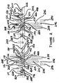
- FIGURES 1-6 a new and improved dual pattern shim assembly, for use in conjunction with, for example, a hot melt adhesive applicator or head, as constructed in accordance with the principles and teachings of the present invention, is disclosed and is generally indicated by the reference character 100.
- the new and improved dual pattern shim assembly 100 for use in conjunction with, for example, a hot melt adhesive applicator or head, and for depositing or applying multiple deposits or patterns onto an underlying substrate, comprises a die adaptor 102, a first pattern shim 104, a separation shim 106, a second pattern shim 108, and a die plate 110, wherein the underlying substrate will be movable relative to the new and improved dual pattern shim assembly 100 along a flow path FP.
- the new and improved dual pattern shim assembly 100 will be described as if two different types of adhesives, coatings, substances, or materials are being conducted through and discharged from the new and improved dual pattern shim assembly 100 so as to be deposited or applied onto the underlying substrate, however, it is to be appreciated that the two different types of adhesives, coatings, substances, or materials can actually comprise multiple different types of adhesives, coatings, substances, or materials, or the same adhesive, coating, substance, or material but may be differentiated from each other in that the two different adhesives, coatings, substances, or materials may comprise or be characterized by different thickness dimensions or different patterns, all as will be explained more fully hereinafter.
- the die adaptor 102 has a substantially trapezoidal cross-sectional configuration, and that the upper surface portion 112 of the die adaptor 102 is provided with, for example, eight fluid inlet ports 114,116,118,120,122,124,126, 128 for providing the die adaptor 102 with, for example, eight separate supplies of, for example, hot melt adhesive materials which are supplied thereto, for example, by means of a suitable number of pumps, not shown, although the fluid flows from the pumps are schematically illustrated by inlet arrows within FIGURE 2 .
- the eight fluid inlet ports 114,116,118,120,122,124,126,128 are disposed within two laterally or transversely spaced sets of fluid inlet ports with each set of fluid inlet ports comprising four fluid inlet ports, and four pumps, not shown, are utilized to respectively supply two different fluids, such as, for example, two different hot melt adhesive materials, to the eight fluid inlet ports 114,116,118,120,122,124, 126,128, although it is to be noted that, in accordance with other possible arrangements or embodiments which may be constructed in accordance with the general principles and teachings of the present invention, a larger or smaller number of pumps may in fact be provided in conjunction with the assembly 100.
- each pump will supply a particular one of two fluids or hot melt adhesive materials to four of the eight fluid inlet ports 114,116,118,120,122,124,126,128, or alternatively, eight different pumps, not shown, may be utilized whereby each pump will directly supply a respective one of eight different fluids or hot melt adhesive materials to the eight fluid inlet ports 114,116,118,120,122,124,126,128.
- a first one of the aforenoted two pumps will supply a first one of the two different hot melt adhesive materials to the fluid inlet ports 118, 120,122,124 defined within the upper surface portion 112 of the die adaptor 102, and it is seen that the forwardly facing surface portion 130 of the die adaptor 102 is provided with a plurality of flow channels 132,134,136,138 which are adapted to be respectively fluidically connected, at the upstream end portions thereof, to the fluid inlet ports 118,120,122,124.
- downstream end portions of the plurality of flow channels 132,134,136,138 are respectively fluidically connected to a plurality of fluid discharge ports 140,142,144, 146 which are also defined within the forwardly facing surface portion 130 of the die adaptor 102, and still further, the plurality of fluid discharge ports 140,142,144,146 are adapted to be respectively fluidically connected to a plurality of first fluid deposition or application ports 148,150, 152,154 which are defined within the lower edge portion of the first pattern shim 104 and which will therefore deposit or apply the first fluid, or the first one of the two different hot melt adhesive materials, onto the underlying substrate in accordance with a predetermined pattern, thickness coating, or the like.
- a plurality of 0-ring members 156,158,160,162,164, 166,168,170 are adapted to be respectively operatively associated with the plurality of fluid inlet ports 114,116,118,120,122,124,126,128 so as to provide desired fluid sealing in connection therewith.
- forwardly facing surface portion 130 of the die adaptor 102 is also provided with a plurality of flow channels 172,174,176,178 which are adapted to be respectively fluidically connected, at the upstream end portions thereof, to the fluid inlet ports 114,116,126,128, and, in turn, the downstream end portions of the plurality of flow channels 172,174,176,178 are adapted to be respectively fluidically connected to a first set of through-bores or holes 180,182,184,186 which are defined within the first pattern shim 104.
- the separation shim 106 is likewise provided with a second set of holes or through-bores 188,190,192,194 which are adapted to be respectively fluidically connected to the first set of through-bores or holes 180,182,184,186 defined within the first pattern shim 104. Still further, a third set of through-bores or holes 196,198,200,202 are defined within the second pattern shim 108 and are adapted to be respectively fluidically connected to the second set of through-bores or holes 188,190,192,194 which are defined within the separation shim 106.
- a plurality of flow channels 204,206,208,210 are defined upon or within the rearwardly facing surface portion 212 of the die plate 110, as can best be seen from FIGURE 2 , and that the plurality of flow channels 204,206,208,210 are adapted to be respectively fluidically connected, at the upstream end portions thereof, to the third set of through-bores or holes 196,198,200,202 which are defined within the second pattern shim 108 so as to receive the second fluid therefrom, while the downstream end portions of the flow channels 204,206,208,210 are adapted to be respectively fluidically connected to a plurality of fluid discharge ports 214,216,218,220, which are also defined within the rearwardly facing surface portion 212 of the die plate 110, so as to supply the second fluid thereto.
- the plurality of fluid discharge ports 214,216,218,220 are adapted to be respectively fluidically connected to a plurality of second fluid deposition or application ports 222,224, 226,228 which are defined within the lower edge portion of the second pattern shim 108 and which will therefore serve to deposit or apply the second fluid, or the second one of the two different hot melt adhesive materials, onto the underlying substrate in accordance with a predetermined pattern, coating thickness, or the like.
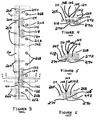
- FIGURES 3-6 in addition to FIGURES 1 and 2 , the assembling procedure of the new and improved dual pattern shim assembly 100, as well as the mounting of the new and improved dual pattern shim assembly onto a hot melt adhesive applicator or head, will now be described.
- left side portions of the die adaptor 102, the first pattern shim 104, the separation shim 106, the second pattern shim 108, and the die plate 110 are respectively provided with first bores or apertures 230,232, 234,236,238 for accommodating a first dowel pin 240 which is adapted to be inserted through the aforenoted bores or apertures 230,232,234,236,238 so as to effectively align the left side portions of the die adaptor 102, the first pattern shim 104, the separation shim 106, the second pattern shim 108, and the die plate 110 together.
- right side portions of the die adaptor 102, the first pattern shim 104, the separation shim 106, the second pattern shim 108, and the die plate 110 are respectively provided with second bores or apertures 242,244,246,248,250 for accommodating a second dowel pin 252 which is adapted to be inserted through the aforenoted bores or apertures 242,244,246,248,250 so as to effectively align the right side portions of the die adaptor 102, the first pattern shim 104, the separation shim 106, the second pattern shim 108, and the die plate 110 together.
- each one of the die adaptor 102, the first pattern shim 104, the separation shim 106, the second pattern shim 108, and the die plate 110 components is also respectively provided with a plurality of apertures or bores, such as, for example, ten apertures of bores, 254,256,258,260,262 which are disposed within a horizontal array and which are adapted to respectively receive therethrough a plurality of suitable bolt fasteners, that is, ten bolt fasteners 264 so as to in fact fixedly secure the die adaptor 102, the first pattern shim 104, the separation shim 106, the second pattern shim 108, and the die plate 110 together in order to form the new and improved dual pattern shim assembly 100.
- a plurality of apertures or bores such as, for example, ten apertures of bores, 254,256,258,260,262 which are disposed within a horizontal array and which are adapted to respectively receive therethrough a plurality of suitable bolt fasteners, that is
- the die adaptor 102 is provided with a plurality of vertically oriented bores, such as, for example, seven bores 266, within which a plurality of bolt fasteners, such as, for example, seven bolt fasteners 268, are adapted to be inserted for threaded engagement within an undersurface portion of the hot melt adhesive applicator or head, not shown, in order to fixedly mount the new and improved dual pattern shim assembly 100 thereon.
- a plurality of vertically oriented bores such as, for example, seven bores 266, within which a plurality of bolt fasteners, such as, for example, seven bolt fasteners 268, are adapted to be inserted for threaded engagement within an undersurface portion of the hot melt adhesive applicator or head, not shown, in order to fixedly mount the new and improved dual pattern shim assembly 100 thereon.
- the bottom edge portion 270 of the forwardly facing surface portion 130 of the trapezoidal-shaped die adaptor 102 projects downwardly beneath, for example, the lower or inclined bottom surface portion 272 of the die adaptor 102 so as to form what is known as a knife edge.
- the rearwardly facing or extending bottom edge portion of the die plate 110 terminates in an arcuately shaped portion 274 which is known as an eagle beak, and that the first pattern shim 104, the separation shim 106, and the second pattern shim 108 are effectively sandwiched between the die adaptor 102 and the die plate 110 such that the respective lower edge portions 276,278,280 of the first pattern shim 104, the separation shim 106, and the second pattern shim 108 are effectively aligned with, or disposed at the same elevational level as, the knife edge 270 of the die adaptor 102 and the terminal edge portion of the eagle beak 274.
- the separation shim 106 is provided with a relatively small thickness dimension which not only permits the lower edge portions 276,280 of the first and second pattern shims 104,108 to be physically located relatively close to each other, but in addition, to permit both of the lower edge portions 276,280 of the first and second pattern shims 104,108 to also be physically located relatively close to the knife edge 270 of the die adaptor 102.
- such a composite assembly defines a sharply edged structure which permits the desired patterns to in fact be deposited or applied onto the underlying substrate as desirably crisp, sharp, and clean images when in fact, for example, hot melt adhesive material is dispensed or discharged from, and deposited or applied onto the underlying substrate, by means of either one of the pattern shims 104,108.
- a first deposition or application pattern 282 comprising a first hot melt adhesive material, is deposited or applied onto the underlying substrate by means of the fluid deposition port 148 defined within the lower edge portion 276 of the first pattern shim 104, and it is seen that such first deposition or application pattern 282 has predetermined length and width dimensions.
- this first deposition or application pattern 282 preferably has a first predetermined thickness dimension.
- a second deposition or application pattern 284 comprising the same hot melt adhesive material as that utilized in forming the first deposition or application pattern 282, is deposited or applied onto the underlying substrate by means of the fluid deposition port 150 which is also defined within the lower edge portion 276 of the first pattern shim 104, and it is seen that such second deposition or application pattern 284 has a predetermined length dimension which is substantially the same as that of the first deposition or application pattern 284, however, it is also appreciated that the second deposition or application pattern 284 is effectively longitudinally offset with respect to the first deposition or application pattern 282 as a result of the suitably timed operation of the dispensing valving structure, not shown, disposed within the applicator or head, also not shown.
- the width dimension of the second deposition or application pattern 284 is somewhat smaller or narrower than that of the first deposition or application pattern 282 as determined, for example, by the relative width dimensions of the fluid depositions ports 148,150.
- this second deposition or application pattern 284 preferably has a predetermined thickness dimension which is substantially the same as that of the first deposition or application pattern 282.
- third and fourth deposition or application patterns 286,288, respectively similar to the first and second deposition or application patterns 282,284 are formed by the corresponding fluid deposition ports 154,152 which are likewise defined within the lower edge portion 276 of the first pattern shim 104.
- a fifth deposition or application pattern 290 comprising a second hot melt adhesive material, is deposited or applied onto the underlying substrate by means of the fluid deposition port 222 defined within the lower edge portion 280 of the second pattern shim 108, and it is seen that such fifth deposition or application pattern 290 also has predetermined length and width dimensions.
- this fifth deposition or application pattern 290 preferably has a second predetermined thickness dimension which may be greater than or less than that of, for example, any one of the deposition or application patterns 282,284,286,288.
- a sixth deposition or application pattern 292 comprising, for example, the same second hot melt adhesive material as that utilized in forming the fifth deposition or application pattern 290, is deposited or applied onto the underlying substrate by means of the fluid deposition port 224 which is also defined within the lower edge portion 280 of the second pattern shim 108, and it is seen that such second deposition or application pattern 292 has predetermined length and width dimensions which are substantially the same as those of the fifth deposition or application pattern 290, however, it is also appreciated that the sixth deposition or application pattern 292 is effectively longitudinally offset with respect to the fifth deposition or application pattern 290 as a result of the suitably timed operation of, for example, the dispensing valving structure, not shown, disposed within the applicator or head, also not shown, whereby the particular first and second hot melt adhesive materials are dispensed at predetermined times relative to the movement of the underlying substrate along the flow path FP.
- this sixth deposition or application pattern 292 preferably has a predetermined thickness dimension which is substantially the same as that of the fifth deposition or application pattern 290.
- seventh and eighth deposition or application patterns 294,296, respectively similar to the fifth and sixth deposition or application patterns 290,292, are formed by the corresponding fluid deposition ports 228,226 which are likewise defined within the lower edge portion 280 of the second pattern shim 108.
- a trailing edge portion of the first deposition or application pattern 282 is overlapped by means of a leading edge portion of the sixth deposition or application pattern 292, and similarly with respect to the trailing edge portion of the third deposition or application pattern 286 which is overlapped by means of the leading edge portion of the eighth deposition or application pattern 296.
- this is achieved as a result of, for example, the particular timing of the dispensing valve structure, not shown, disposed within the applicator or head, also not shown, whereby the particular first and second hot melt adhesive materials are dispensed at predetermined times relative to the movement of the underlying substrate along the flow path FP.
- the overlapped deposition or application of the two different hot melt adhesive materials atop one another is also achieved as a result of the unique contact or engagement of the entire aforenoted new and improved dual pattern shim assembly 100 of the present invention, as comprising, for example, the knife edge structure 270 of the die adaptor 102, the lower edge portion 276 of the first pattern shim 104, the lower edge portion 278 of the separation shim 106, the lower edge portion 280 of the second pattern shim 108, and the terminal edge section of the eagle beak portion 274 of the die plate 110, with the underlying substrate.
- the underlying substrate will, in effect, be slightly indented or depressed, not only as a result of the contact or engagement of the underlying substrate by means of the dual pattern shim assembly 100, but in addition, as a result of the pressure of the holt melt adhesive material being dispensed or discharged from, for example, the first pattern shim 104.
- the hot melt adhesive being dispensed or discharged from the second pattern shim 108, will in fact be able to be deposited or applied onto the underlying substrate within such secondary indented or depressed region by means of the second pattern shim 108, and atop the first deposition or application pattern 282 in an overlying or overlapping manner, so as not to disturb or otherwise adversely affect the previously applied first deposition or application pattern 282.
- FIGURE 7 it is also seen that alternative or converse deposition or application patterns 282,284,286,288,290,292,294,296, with respect to the deposition or application patterns 282,284,286,288, 290,292,294,296 as disclosed within, for example, FIGURE 2 , can likewise be achieved.
- the trailing edge portion of the sixth deposition or application pattern 292 is now effectively overlapped by means of the leading edge portion of the first deposition or application pattern 282, and similarly with respect to the trailing edge portion of the eighth deposition or application pattern 296 being overlapped by means of the leading edge portion of the third deposition or application pattern 286.
- the separation shim 106 has been noted as being important in that the same not only permits the first and second pattern shims 104,108 to be disposed extremely close to each other, but in addition, permits the pattern shims 104,108 to be disposed extremely close to the knife edge 270 of the die adaptor 102.
- the deposition of the first hot melt adhesive material from, for example, the first pattern shim 104 will be distorted, and will not be cleanly or crisply defined, because the relatively wide separation shim 106 will, in effect, tend to enhance the dwell time or deposition time of the deposition of the hot melt adhesive material being dispensed by the first pattern shim 104 whereby the pattern of such hot melt adhesive material will effectively be distorted.
- the deposition pattern of the hot melt adhesive material being dispensed from the second pattern shim 108 will, in effect, be distorted because sufficient time for providing the aforenoted indenting or depression, into which the second deposition or application of the hot melt adhesive material from, for example, the second pattern shim 108, will not in fact have been able to have been effectuated.
- the hot melt adhesive material being dispensed from the second pattern shim 108 in a truly overlapping manner with respect to the hot melt adhesive material that was dispensed from the first pattern shim 104
- the hot melt adhesive material, being dispensed from the second pattern shim 108 will, in effect, commingle with the hot melt adhesive material previously deposited onto the underlying substrate from the first pattern shim 104.
- the separation shim 106 having the correct thickness dimension, along with other operational or dispensing factors, such as, for example, the particular hot melt adhesive material being dispensed, its viscosity properties, the pressure of the hot melt adhesive material being dispensed, all affect the successful deposition or application of the particular patterns onto the underlying substrate.
- a new and improved dual pattern shim assembly for use in conjunction with hot melt adhesive dispensing systems, wherein various different overlapping or overlying deposition or application patterns, having different length dimensions, different width dimensions, different coating thicknesses, different longitudinal positional locations or dispositions with respect to each other, and the like, can be achieved by means of the new and improved dual pattern shim assembly of the present invention during a single pass of the underlying substrate with respect to the hot melt adhesive contact die applicator or head.
- different or multiple adhesive deposition or application procedures are able to effectively be accomplished simultaneously so as to effectively simplify and shorten the overall assembly lines and production times required for the fabrication or manufacture of various different particular products.
Landscapes
- Coating Apparatus (AREA)
- Adhesives Or Adhesive Processes (AREA)
- Application Of Or Painting With Fluid Materials (AREA)
- Lining Or Joining Of Plastics Or The Like (AREA)
- Adhesive Tapes (AREA)
Priority Applications (1)
| Application Number | Priority Date | Filing Date | Title |
|---|---|---|---|
| PL08744766T PL2144708T3 (pl) | 2007-04-06 | 2008-03-31 | Zespół podkładek regulacyjnych w podwójnym wzorze do stosowania z układami dozowania kleju topliwego |
Applications Claiming Priority (3)
| Application Number | Priority Date | Filing Date | Title |
|---|---|---|---|
| US90753507P | 2007-04-06 | 2007-04-06 | |
| US12/073,374 US10137472B2 (en) | 2007-04-06 | 2008-03-05 | Dual pattern shim assembly for use in conjunction with hot melt adhesive dispensing systems |
| PCT/US2008/058887 WO2008124367A1 (en) | 2007-04-06 | 2008-03-31 | Dual pattern shim assembly for use in conjunction with hot melt adhesive dispensing systems |
Publications (2)
| Publication Number | Publication Date |
|---|---|
| EP2144708A1 EP2144708A1 (en) | 2010-01-20 |
| EP2144708B1 true EP2144708B1 (en) | 2015-01-21 |
Family
ID=39825854
Family Applications (1)
| Application Number | Title | Priority Date | Filing Date |
|---|---|---|---|
| EP08744766.0A Active EP2144708B1 (en) | 2007-04-06 | 2008-03-31 | Dual pattern shim assembly for use in conjunction with hot melt adhesive dispensing systems |
Country Status (10)
| Country | Link |
|---|---|
| US (1) | US10137472B2 (https=) |
| EP (1) | EP2144708B1 (https=) |
| JP (1) | JP5731191B2 (https=) |
| KR (1) | KR20090129457A (https=) |
| CN (2) | CN101678385A (https=) |
| BR (1) | BRPI0809914B1 (https=) |
| MX (1) | MX2009010821A (https=) |
| PL (1) | PL2144708T3 (https=) |
| RU (1) | RU2432213C2 (https=) |
| WO (1) | WO2008124367A1 (https=) |
Cited By (1)
| Publication number | Priority date | Publication date | Assignee | Title |
|---|---|---|---|---|
| JP2010523317A (ja) * | 2007-04-06 | 2010-07-15 | イリノイ トゥール ワークス インコーポレイティド | ホットメルト接着剤供給システムとの関連において用いられる複式型板組立体 |
Families Citing this family (21)
| Publication number | Priority date | Publication date | Assignee | Title |
|---|---|---|---|---|
| US8186296B2 (en) | 2010-05-05 | 2012-05-29 | The Procter & Gamble Company | Methods and apparatus for applying adhesives in patterns to an advancing substrate |
| JP5315453B1 (ja) * | 2012-03-07 | 2013-10-16 | 日東電工株式会社 | シム部材、ダイコーター及び塗布膜の製造方法 |
| US9682392B2 (en) | 2012-04-11 | 2017-06-20 | Nordson Corporation | Method for applying varying amounts or types of adhesive on an elastic strand |
| US9034425B2 (en) | 2012-04-11 | 2015-05-19 | Nordson Corporation | Method and apparatus for applying adhesive on an elastic strand in a personal disposable hygiene product |
| US9265672B2 (en) | 2012-11-27 | 2016-02-23 | The Procter & Gamble Company | Methods and apparatus for applying adhesives in patterns to an advancing substrate |
| US9295590B2 (en) | 2012-11-27 | 2016-03-29 | The Procter & Gamble Company | Method and apparatus for applying an elastic material to a moving substrate in a curved path |
| US9248054B2 (en) | 2012-11-27 | 2016-02-02 | The Procter & Gamble Company | Methods and apparatus for making elastic laminates |
| US10150136B2 (en) | 2014-06-10 | 2018-12-11 | Illinois Tool Works Inc. | Rapid changeover slot die assembly for a fluid application device |
| US9724722B2 (en) * | 2014-06-10 | 2017-08-08 | Illinois Tool Works Inc. | Rapid changeover slot die assembly for a fluid application device |
| US9718085B2 (en) * | 2015-04-20 | 2017-08-01 | Illinois Tool Works Inc. | Hot melt adhesive applicator system with small footprint |
| US10081022B2 (en) | 2015-09-15 | 2018-09-25 | Illinois Tool Works Inc. | Die mounted contact applicator |
| US9889599B2 (en) | 2015-09-15 | 2018-02-13 | Illinois Tool Works Inc. | Multi-temperature contact applicator |
| FR3054771B1 (fr) * | 2016-07-27 | 2020-11-06 | Saint Gobain | Vitrage muni d'un dispositif conducteur electrique avec zones de soudure ameliorees |
| ES2847950T3 (es) | 2016-09-08 | 2021-08-04 | Nordson Corp | Aplicador con placa de desvío |
| ES2676356B1 (es) * | 2017-01-18 | 2019-05-14 | Valco Melton S L U | Cabezal para la aplicacion de adhesivo termofusible |
| DE102018102500A1 (de) * | 2018-02-05 | 2019-08-08 | Hauni Maschinenbau Gmbh | Beleimungsvorrichtung für eine Maschine zur Herstellung von Produkten der Tabak verarbeitenden Industrie und Konturplatte für eine Auftragsdüse für eine derartige Beleimungsvorrichtung |
| US11707548B2 (en) | 2018-10-09 | 2023-07-25 | The Procter & Gamble Company | Absorbent article comprising a lotion resistant polymeric filler composition |
| CN112718381B (zh) * | 2019-10-14 | 2021-12-10 | 怡定兴科技股份有限公司 | 狭缝式涂布模头及狭缝式涂布装置 |
| EP3825012A1 (en) * | 2019-11-22 | 2021-05-26 | Bostik Sa | Use of a blank shim plate for preventing drooling in die slot coating |
| JP7593741B2 (ja) | 2020-03-26 | 2024-12-03 | ノードソン コーポレーション | ノズル、接着剤塗布ヘッド、接着剤塗布装置及びおむつ製造方法 |
| CN113769490B (zh) * | 2021-08-19 | 2022-12-30 | 江苏鼎盛滤袋有限公司 | 一种复合热熔滤袋及其制备工艺 |
Family Cites Families (18)
| Publication number | Priority date | Publication date | Assignee | Title |
|---|---|---|---|---|
| US256496A (en) * | 1882-04-18 | Coffin | ||
| US3448183A (en) * | 1966-08-05 | 1969-06-03 | Dow Chemical Co | Method for the preparation of multilayer film |
| US4476165A (en) | 1982-06-07 | 1984-10-09 | Acumeter Laboratories, Inc. | Method of and apparatus for multi-layer viscous fluid deposition such as for the application of adhesives and the like |
| US4774109A (en) | 1987-07-21 | 1988-09-27 | Nordson Corporation | Method and apparatus for applying narrow, closely spaced beads of viscous liquid to a substrate |
| JPH0639824Y2 (ja) | 1990-02-24 | 1994-10-19 | アイカ工業株式会社 | 塗布装置 |
| US5728430A (en) * | 1995-06-07 | 1998-03-17 | Avery Dennison Corporation | Method for multilayer coating using pressure gradient regulation |
| SE508164C2 (sv) * | 1995-08-03 | 1998-09-07 | Moelnlycke Ab | Adhesiv fastsättningsanordning samt alster försett med en sådan fastsättningsanordning |
| US5871585A (en) | 1996-03-20 | 1999-02-16 | Minnesota Mining And Maufacturing Company | Apparatus for applying a fluid to a moving web of material |
| JPH10277460A (ja) * | 1997-04-07 | 1998-10-20 | Matsushita Electric Ind Co Ltd | 塗布装置 |
| JPH11226469A (ja) | 1998-02-16 | 1999-08-24 | Nitto Denko Corp | ストライプ塗工方法及び粘着テープの製造方法並びにストライプ塗工用ダイ |
| US6601741B2 (en) | 2001-11-28 | 2003-08-05 | Illinois Tool Works Inc. | Laminated distribution manifold plate system |
| JP2003275651A (ja) | 2002-03-20 | 2003-09-30 | Hitachi Maxell Ltd | 塗布装置 |
| US7152815B2 (en) | 2003-06-04 | 2006-12-26 | Nordson Corporation | Dispensing system, nozzle and method for independently dispensing and controlling liquid |
| JP4767482B2 (ja) | 2003-07-08 | 2011-09-07 | ノードソン コーポレーション | 液体又は溶融体の塗布方法及びノズル |
| JP4573550B2 (ja) | 2004-03-23 | 2010-11-04 | 東レエンジニアリング株式会社 | 塗工装置 |
| JP2006015235A (ja) | 2004-07-01 | 2006-01-19 | Nordson Corp | スロットダイ、多孔質材料に液体を充填する方法、多孔質木製板の縁部を処理する方法、チップボード及びパーチクルボード |
| JP4682565B2 (ja) | 2004-09-06 | 2011-05-11 | パナソニック電工株式会社 | 塗工ヘッドとそれを用いた塗工装置、貼り合わせ装置 |
| US10137472B2 (en) * | 2007-04-06 | 2018-11-27 | Illinois Tool Works Inc. | Dual pattern shim assembly for use in conjunction with hot melt adhesive dispensing systems |
-
2008
- 2008-03-05 US US12/073,374 patent/US10137472B2/en active Active
- 2008-03-31 CN CN200880014488A patent/CN101678385A/zh active Pending
- 2008-03-31 JP JP2010502233A patent/JP5731191B2/ja active Active
- 2008-03-31 PL PL08744766T patent/PL2144708T3/pl unknown
- 2008-03-31 CN CN201610119045.XA patent/CN105728261B/zh active Active
- 2008-03-31 BR BRPI0809914A patent/BRPI0809914B1/pt active IP Right Grant
- 2008-03-31 KR KR1020097020894A patent/KR20090129457A/ko not_active Ceased
- 2008-03-31 WO PCT/US2008/058887 patent/WO2008124367A1/en not_active Ceased
- 2008-03-31 MX MX2009010821A patent/MX2009010821A/es active IP Right Grant
- 2008-03-31 EP EP08744766.0A patent/EP2144708B1/en active Active
- 2008-03-31 RU RU2009140972/05A patent/RU2432213C2/ru active
Cited By (1)
| Publication number | Priority date | Publication date | Assignee | Title |
|---|---|---|---|---|
| JP2010523317A (ja) * | 2007-04-06 | 2010-07-15 | イリノイ トゥール ワークス インコーポレイティド | ホットメルト接着剤供給システムとの関連において用いられる複式型板組立体 |
Also Published As
| Publication number | Publication date |
|---|---|
| CN101678385A (zh) | 2010-03-24 |
| WO2008124367A1 (en) | 2008-10-16 |
| MX2009010821A (es) | 2009-11-10 |
| CN105728261A (zh) | 2016-07-06 |
| EP2144708A1 (en) | 2010-01-20 |
| RU2432213C2 (ru) | 2011-10-27 |
| US20080245298A1 (en) | 2008-10-09 |
| CN105728261B (zh) | 2022-09-16 |
| JP2010523317A (ja) | 2010-07-15 |
| BRPI0809914B1 (pt) | 2020-01-14 |
| KR20090129457A (ko) | 2009-12-16 |
| RU2009140972A (ru) | 2011-05-20 |
| BRPI0809914A2 (pt) | 2014-10-07 |
| JP5731191B2 (ja) | 2015-06-10 |
| PL2144708T3 (pl) | 2015-06-30 |
| US10137472B2 (en) | 2018-11-27 |
Similar Documents
| Publication | Publication Date | Title |
|---|---|---|
| EP2144708B1 (en) | Dual pattern shim assembly for use in conjunction with hot melt adhesive dispensing systems | |
| JPH01503688A (ja) | 接着剤塗布器アセンブリ | |
| US10717222B2 (en) | Multi-lane die | |
| US5000988A (en) | Method of applying a coating of viscous materials | |
| US20110014430A1 (en) | Metering system for hot melt adhesives with variable adhesive volumes | |
| EP1497043B1 (en) | Nozzle and method for dispensing controlled patterns of liquid material | |
| DE102010038635A1 (de) | Beschichtungsdüse, Beschichtungsverfahren und Innenvolumen-Regelventil | |
| SK285998B6 (sk) | Zariadenie a spôsob nanášania lepidla | |
| WO2014190578A1 (zh) | 涂布喷头、具有该涂布喷头的涂布装置及其涂布方法 | |
| JP2014008465A (ja) | ダイヘッド、丁合装置およびダイヘッドのスリットの隙間の大きさの調整方法 | |
| CN102310027A (zh) | 具有自动关闭功能的多槽涂敷器 | |
| JP2010005508A (ja) | スロットコートガン | |
| US20060081727A1 (en) | Auto-tracking dispenser | |
| JPH08318196A (ja) | スロット・ノズル | |
| JPH10277460A (ja) | 塗布装置 | |
| US7611071B2 (en) | Intermittently operable recirculating control module and dispensing nozzle having internally disposed fixed orifice | |
| US9283579B2 (en) | Variable volume hot melt adhesive dispensing nozzle or die assembly with choke suppression | |
| US20190299241A1 (en) | Device For Applying A Flowable Substance To A Substrate | |
| JP2016078012A (ja) | 塗布器 | |
| JP2010184434A (ja) | 基板接合方法及びインクジェットヘッド並びに画像形成装置 | |
| US20040108396A1 (en) | Auto-tracking dispenser | |
| JP5223223B2 (ja) | ダイヘッド | |
| CN1073509C (zh) | 打印机喷墨头的制造方法 | |
| DE112015007036B4 (de) | Filmbildungsvorrichtung | |
| JP7730193B2 (ja) | 大面積プリンティングのためのスリットノズル |
Legal Events
| Date | Code | Title | Description |
|---|---|---|---|
| PUAI | Public reference made under article 153(3) epc to a published international application that has entered the european phase |
Free format text: ORIGINAL CODE: 0009012 |
|
| 17P | Request for examination filed |
Effective date: 20091022 |
|
| AK | Designated contracting states |
Kind code of ref document: A1 Designated state(s): AT BE BG CH CY CZ DE DK EE ES FI FR GB GR HR HU IE IS IT LI LT LU LV MC MT NL NO PL PT RO SE SI SK TR |
|
| AX | Request for extension of the european patent |
Extension state: AL BA MK RS |
|
| DAX | Request for extension of the european patent (deleted) | ||
| 17Q | First examination report despatched |
Effective date: 20101018 |
|
| RAP1 | Party data changed (applicant data changed or rights of an application transferred) |
Owner name: ILLINOIS TOOL WORKS INC. |
|
| GRAP | Despatch of communication of intention to grant a patent |
Free format text: ORIGINAL CODE: EPIDOSNIGR1 |
|
| INTG | Intention to grant announced |
Effective date: 20141022 |
|
| GRAS | Grant fee paid |
Free format text: ORIGINAL CODE: EPIDOSNIGR3 |
|
| GRAA | (expected) grant |
Free format text: ORIGINAL CODE: 0009210 |
|
| AK | Designated contracting states |
Kind code of ref document: B1 Designated state(s): AT BE BG CH CY CZ DE DK EE ES FI FR GB GR HR HU IE IS IT LI LT LU LV MC MT NL NO PL PT RO SE SI SK TR |
|
| REG | Reference to a national code |
Ref country code: GB Ref legal event code: FG4D |
|
| REG | Reference to a national code |
Ref country code: CH Ref legal event code: EP |
|
| REG | Reference to a national code |
Ref country code: IE Ref legal event code: FG4D |
|
| REG | Reference to a national code |
Ref country code: AT Ref legal event code: REF Ref document number: 707652 Country of ref document: AT Kind code of ref document: T Effective date: 20150215 |
|
| REG | Reference to a national code |
Ref country code: DE Ref legal event code: R096 Ref document number: 602008036453 Country of ref document: DE Effective date: 20150305 |
|
| REG | Reference to a national code |
Ref country code: SE Ref legal event code: TRGR |
|
| REG | Reference to a national code |
Ref country code: NL Ref legal event code: VDEP Effective date: 20150121 |
|
| REG | Reference to a national code |
Ref country code: AT Ref legal event code: MK05 Ref document number: 707652 Country of ref document: AT Kind code of ref document: T Effective date: 20150121 |
|
| REG | Reference to a national code |
Ref country code: LT Ref legal event code: MG4D |
|
| REG | Reference to a national code |
Ref country code: PL Ref legal event code: T3 |
|
| PG25 | Lapsed in a contracting state [announced via postgrant information from national office to epo] |
Ref country code: NO Free format text: LAPSE BECAUSE OF FAILURE TO SUBMIT A TRANSLATION OF THE DESCRIPTION OR TO PAY THE FEE WITHIN THE PRESCRIBED TIME-LIMIT Effective date: 20150421 Ref country code: BG Free format text: LAPSE BECAUSE OF FAILURE TO SUBMIT A TRANSLATION OF THE DESCRIPTION OR TO PAY THE FEE WITHIN THE PRESCRIBED TIME-LIMIT Effective date: 20150421 Ref country code: HR Free format text: LAPSE BECAUSE OF FAILURE TO SUBMIT A TRANSLATION OF THE DESCRIPTION OR TO PAY THE FEE WITHIN THE PRESCRIBED TIME-LIMIT Effective date: 20150121 Ref country code: LT Free format text: LAPSE BECAUSE OF FAILURE TO SUBMIT A TRANSLATION OF THE DESCRIPTION OR TO PAY THE FEE WITHIN THE PRESCRIBED TIME-LIMIT Effective date: 20150121 Ref country code: ES Free format text: LAPSE BECAUSE OF FAILURE TO SUBMIT A TRANSLATION OF THE DESCRIPTION OR TO PAY THE FEE WITHIN THE PRESCRIBED TIME-LIMIT Effective date: 20150121 Ref country code: FI Free format text: LAPSE BECAUSE OF FAILURE TO SUBMIT A TRANSLATION OF THE DESCRIPTION OR TO PAY THE FEE WITHIN THE PRESCRIBED TIME-LIMIT Effective date: 20150121 |
|
| PG25 | Lapsed in a contracting state [announced via postgrant information from national office to epo] |
Ref country code: LV Free format text: LAPSE BECAUSE OF FAILURE TO SUBMIT A TRANSLATION OF THE DESCRIPTION OR TO PAY THE FEE WITHIN THE PRESCRIBED TIME-LIMIT Effective date: 20150121 Ref country code: AT Free format text: LAPSE BECAUSE OF FAILURE TO SUBMIT A TRANSLATION OF THE DESCRIPTION OR TO PAY THE FEE WITHIN THE PRESCRIBED TIME-LIMIT Effective date: 20150121 Ref country code: GR Free format text: LAPSE BECAUSE OF FAILURE TO SUBMIT A TRANSLATION OF THE DESCRIPTION OR TO PAY THE FEE WITHIN THE PRESCRIBED TIME-LIMIT Effective date: 20150422 Ref country code: NL Free format text: LAPSE BECAUSE OF FAILURE TO SUBMIT A TRANSLATION OF THE DESCRIPTION OR TO PAY THE FEE WITHIN THE PRESCRIBED TIME-LIMIT Effective date: 20150121 Ref country code: IS Free format text: LAPSE BECAUSE OF FAILURE TO SUBMIT A TRANSLATION OF THE DESCRIPTION OR TO PAY THE FEE WITHIN THE PRESCRIBED TIME-LIMIT Effective date: 20150521 |
|
| REG | Reference to a national code |
Ref country code: DE Ref legal event code: R097 Ref document number: 602008036453 Country of ref document: DE |
|
| PG25 | Lapsed in a contracting state [announced via postgrant information from national office to epo] |
Ref country code: CZ Free format text: LAPSE BECAUSE OF FAILURE TO SUBMIT A TRANSLATION OF THE DESCRIPTION OR TO PAY THE FEE WITHIN THE PRESCRIBED TIME-LIMIT Effective date: 20150121 Ref country code: LU Free format text: LAPSE BECAUSE OF FAILURE TO SUBMIT A TRANSLATION OF THE DESCRIPTION OR TO PAY THE FEE WITHIN THE PRESCRIBED TIME-LIMIT Effective date: 20150331 Ref country code: MC Free format text: LAPSE BECAUSE OF FAILURE TO SUBMIT A TRANSLATION OF THE DESCRIPTION OR TO PAY THE FEE WITHIN THE PRESCRIBED TIME-LIMIT Effective date: 20150121 Ref country code: EE Free format text: LAPSE BECAUSE OF FAILURE TO SUBMIT A TRANSLATION OF THE DESCRIPTION OR TO PAY THE FEE WITHIN THE PRESCRIBED TIME-LIMIT Effective date: 20150121 Ref country code: RO Free format text: LAPSE BECAUSE OF FAILURE TO SUBMIT A TRANSLATION OF THE DESCRIPTION OR TO PAY THE FEE WITHIN THE PRESCRIBED TIME-LIMIT Effective date: 20150121 Ref country code: SK Free format text: LAPSE BECAUSE OF FAILURE TO SUBMIT A TRANSLATION OF THE DESCRIPTION OR TO PAY THE FEE WITHIN THE PRESCRIBED TIME-LIMIT Effective date: 20150121 Ref country code: DK Free format text: LAPSE BECAUSE OF FAILURE TO SUBMIT A TRANSLATION OF THE DESCRIPTION OR TO PAY THE FEE WITHIN THE PRESCRIBED TIME-LIMIT Effective date: 20150121 |
|
| REG | Reference to a national code |
Ref country code: CH Ref legal event code: PL |
|
| PLBE | No opposition filed within time limit |
Free format text: ORIGINAL CODE: 0009261 |
|
| STAA | Information on the status of an ep patent application or granted ep patent |
Free format text: STATUS: NO OPPOSITION FILED WITHIN TIME LIMIT |
|
| GBPC | Gb: european patent ceased through non-payment of renewal fee |
Effective date: 20150421 |
|
| 26N | No opposition filed |
Effective date: 20151022 |
|
| REG | Reference to a national code |
Ref country code: FR Ref legal event code: ST Effective date: 20151130 |
|
| REG | Reference to a national code |
Ref country code: IE Ref legal event code: MM4A |
|
| PG25 | Lapsed in a contracting state [announced via postgrant information from national office to epo] |
Ref country code: LI Free format text: LAPSE BECAUSE OF NON-PAYMENT OF DUE FEES Effective date: 20150331 Ref country code: CH Free format text: LAPSE BECAUSE OF NON-PAYMENT OF DUE FEES Effective date: 20150331 Ref country code: IE Free format text: LAPSE BECAUSE OF NON-PAYMENT OF DUE FEES Effective date: 20150331 Ref country code: GB Free format text: LAPSE BECAUSE OF NON-PAYMENT OF DUE FEES Effective date: 20150421 |
|
| PG25 | Lapsed in a contracting state [announced via postgrant information from national office to epo] |
Ref country code: SI Free format text: LAPSE BECAUSE OF FAILURE TO SUBMIT A TRANSLATION OF THE DESCRIPTION OR TO PAY THE FEE WITHIN THE PRESCRIBED TIME-LIMIT Effective date: 20150121 Ref country code: FR Free format text: LAPSE BECAUSE OF NON-PAYMENT OF DUE FEES Effective date: 20150331 |
|
| PG25 | Lapsed in a contracting state [announced via postgrant information from national office to epo] |
Ref country code: BE Free format text: LAPSE BECAUSE OF FAILURE TO SUBMIT A TRANSLATION OF THE DESCRIPTION OR TO PAY THE FEE WITHIN THE PRESCRIBED TIME-LIMIT Effective date: 20150121 |
|
| PG25 | Lapsed in a contracting state [announced via postgrant information from national office to epo] |
Ref country code: MT Free format text: LAPSE BECAUSE OF FAILURE TO SUBMIT A TRANSLATION OF THE DESCRIPTION OR TO PAY THE FEE WITHIN THE PRESCRIBED TIME-LIMIT Effective date: 20150121 |
|
| PG25 | Lapsed in a contracting state [announced via postgrant information from national office to epo] |
Ref country code: HU Free format text: LAPSE BECAUSE OF FAILURE TO SUBMIT A TRANSLATION OF THE DESCRIPTION OR TO PAY THE FEE WITHIN THE PRESCRIBED TIME-LIMIT; INVALID AB INITIO Effective date: 20080331 |
|
| PG25 | Lapsed in a contracting state [announced via postgrant information from national office to epo] |
Ref country code: CY Free format text: LAPSE BECAUSE OF FAILURE TO SUBMIT A TRANSLATION OF THE DESCRIPTION OR TO PAY THE FEE WITHIN THE PRESCRIBED TIME-LIMIT Effective date: 20150121 |
|
| PG25 | Lapsed in a contracting state [announced via postgrant information from national office to epo] |
Ref country code: PT Free format text: LAPSE BECAUSE OF FAILURE TO SUBMIT A TRANSLATION OF THE DESCRIPTION OR TO PAY THE FEE WITHIN THE PRESCRIBED TIME-LIMIT Effective date: 20150521 |
|
| PGFP | Annual fee paid to national office [announced via postgrant information from national office to epo] |
Ref country code: SE Payment date: 20190212 Year of fee payment: 13 |
|
| PGFP | Annual fee paid to national office [announced via postgrant information from national office to epo] |
Ref country code: TR Payment date: 20190322 Year of fee payment: 12 |
|
| PG25 | Lapsed in a contracting state [announced via postgrant information from national office to epo] |
Ref country code: SE Free format text: LAPSE BECAUSE OF NON-PAYMENT OF DUE FEES Effective date: 20200401 |
|
| PG25 | Lapsed in a contracting state [announced via postgrant information from national office to epo] |
Ref country code: PL Free format text: LAPSE BECAUSE OF NON-PAYMENT OF DUE FEES Effective date: 20200331 |
|
| PG25 | Lapsed in a contracting state [announced via postgrant information from national office to epo] |
Ref country code: TR Free format text: LAPSE BECAUSE OF NON-PAYMENT OF DUE FEES Effective date: 20200331 |
|
| P01 | Opt-out of the competence of the unified patent court (upc) registered |
Effective date: 20230606 |
|
| PGFP | Annual fee paid to national office [announced via postgrant information from national office to epo] |
Ref country code: DE Payment date: 20260327 Year of fee payment: 19 |
|
| PGFP | Annual fee paid to national office [announced via postgrant information from national office to epo] |
Ref country code: IT Payment date: 20260319 Year of fee payment: 19 |