EP2143994A1 - Beleuchtungsvorrichtung für Fahrzeug - Google Patents
Beleuchtungsvorrichtung für Fahrzeug Download PDFInfo
- Publication number
- EP2143994A1 EP2143994A1 EP09165188A EP09165188A EP2143994A1 EP 2143994 A1 EP2143994 A1 EP 2143994A1 EP 09165188 A EP09165188 A EP 09165188A EP 09165188 A EP09165188 A EP 09165188A EP 2143994 A1 EP2143994 A1 EP 2143994A1
- Authority
- EP
- European Patent Office
- Prior art keywords
- light emitting
- emitting device
- reflector
- diffusion lens
- light
- Prior art date
- Legal status (The legal status is an assumption and is not a legal conclusion. Google has not performed a legal analysis and makes no representation as to the accuracy of the status listed.)
- Granted
Links
Images


Classifications
-
- B—PERFORMING OPERATIONS; TRANSPORTING
- B60—VEHICLES IN GENERAL
- B60Q—ARRANGEMENT OF SIGNALLING OR LIGHTING DEVICES, THE MOUNTING OR SUPPORTING THEREOF OR CIRCUITS THEREFOR, FOR VEHICLES IN GENERAL
- B60Q1/00—Arrangement of optical signalling or lighting devices, the mounting or supporting thereof or circuits therefor
- B60Q1/02—Arrangement of optical signalling or lighting devices, the mounting or supporting thereof or circuits therefor the devices being primarily intended to illuminate the way ahead or to illuminate other areas of way or environments
- B60Q1/04—Arrangement of optical signalling or lighting devices, the mounting or supporting thereof or circuits therefor the devices being primarily intended to illuminate the way ahead or to illuminate other areas of way or environments the devices being headlights
- B60Q1/14—Arrangement of optical signalling or lighting devices, the mounting or supporting thereof or circuits therefor the devices being primarily intended to illuminate the way ahead or to illuminate other areas of way or environments the devices being headlights having dimming means
- B60Q1/1415—Dimming circuits
-
- B—PERFORMING OPERATIONS; TRANSPORTING
- B60—VEHICLES IN GENERAL
- B60Q—ARRANGEMENT OF SIGNALLING OR LIGHTING DEVICES, THE MOUNTING OR SUPPORTING THEREOF OR CIRCUITS THEREFOR, FOR VEHICLES IN GENERAL
- B60Q1/00—Arrangement of optical signalling or lighting devices, the mounting or supporting thereof or circuits therefor
- B60Q1/02—Arrangement of optical signalling or lighting devices, the mounting or supporting thereof or circuits therefor the devices being primarily intended to illuminate the way ahead or to illuminate other areas of way or environments
- B60Q1/04—Arrangement of optical signalling or lighting devices, the mounting or supporting thereof or circuits therefor the devices being primarily intended to illuminate the way ahead or to illuminate other areas of way or environments the devices being headlights
-
- F—MECHANICAL ENGINEERING; LIGHTING; HEATING; WEAPONS; BLASTING
- F21—LIGHTING
- F21S—NON-PORTABLE LIGHTING DEVICES; SYSTEMS THEREOF; VEHICLE LIGHTING DEVICES SPECIALLY ADAPTED FOR VEHICLE EXTERIORS
- F21S41/00—Illuminating devices specially adapted for vehicle exteriors, e.g. headlamps
- F21S41/10—Illuminating devices specially adapted for vehicle exteriors, e.g. headlamps characterised by the light source
- F21S41/14—Illuminating devices specially adapted for vehicle exteriors, e.g. headlamps characterised by the light source characterised by the type of light source
- F21S41/141—Light emitting diodes [LED]
- F21S41/147—Light emitting diodes [LED] the main emission direction of the LED being angled to the optical axis of the illuminating device
- F21S41/148—Light emitting diodes [LED] the main emission direction of the LED being angled to the optical axis of the illuminating device the main emission direction of the LED being perpendicular to the optical axis
-
- F—MECHANICAL ENGINEERING; LIGHTING; HEATING; WEAPONS; BLASTING
- F21—LIGHTING
- F21S—NON-PORTABLE LIGHTING DEVICES; SYSTEMS THEREOF; VEHICLE LIGHTING DEVICES SPECIALLY ADAPTED FOR VEHICLE EXTERIORS
- F21S41/00—Illuminating devices specially adapted for vehicle exteriors, e.g. headlamps
- F21S41/60—Illuminating devices specially adapted for vehicle exteriors, e.g. headlamps characterised by a variable light distribution
- F21S41/63—Illuminating devices specially adapted for vehicle exteriors, e.g. headlamps characterised by a variable light distribution by acting on refractors, filters or transparent cover plates
- F21S41/635—Illuminating devices specially adapted for vehicle exteriors, e.g. headlamps characterised by a variable light distribution by acting on refractors, filters or transparent cover plates by moving refractors, filters or transparent cover plates
-
- B—PERFORMING OPERATIONS; TRANSPORTING
- B60—VEHICLES IN GENERAL
- B60Q—ARRANGEMENT OF SIGNALLING OR LIGHTING DEVICES, THE MOUNTING OR SUPPORTING THEREOF OR CIRCUITS THEREFOR, FOR VEHICLES IN GENERAL
- B60Q2400/00—Special features or arrangements of exterior signal lamps for vehicles
- B60Q2400/30—Daytime running lights [DRL], e.g. circuits or arrangements therefor
-
- F—MECHANICAL ENGINEERING; LIGHTING; HEATING; WEAPONS; BLASTING
- F21—LIGHTING
- F21V—FUNCTIONAL FEATURES OR DETAILS OF LIGHTING DEVICES OR SYSTEMS THEREOF; STRUCTURAL COMBINATIONS OF LIGHTING DEVICES WITH OTHER ARTICLES, NOT OTHERWISE PROVIDED FOR
- F21V13/00—Producing particular characteristics or distribution of the light emitted by means of a combination of elements specified in two or more of main groups F21V1/00 - F21V11/00
- F21V13/02—Combinations of only two kinds of elements
- F21V13/04—Combinations of only two kinds of elements the elements being reflectors and refractors
-
- F—MECHANICAL ENGINEERING; LIGHTING; HEATING; WEAPONS; BLASTING
- F21—LIGHTING
- F21Y—INDEXING SCHEME ASSOCIATED WITH SUBCLASSES F21K, F21L, F21S and F21V, RELATING TO THE FORM OR THE KIND OF THE LIGHT SOURCES OR OF THE COLOUR OF THE LIGHT EMITTED
- F21Y2115/00—Light-generating elements of semiconductor light sources
- F21Y2115/10—Light-emitting diodes [LED]
Definitions
- the present invention relates to a lighting device for a vehicle.
- the lighting device includes a light distribution forming reflector taking a shape of a paraboloid and a light emitting device as a light source disposed on a focal point of the reflector.
- the light distribution forming reflector and the light emitting device are provided in a lamp housing formed by a lamp body and a front cover.
- the lighting device can switch a light distribution formed by the reflector into a headlamp mode and a marker lamp mode by increasing/decreasing a current to be supplied to the light emitting device through a dimming portion.
- JP-A-2004-276740 Publication describes a related art lighting device for a vehicle which includes a plurality of projection type light source units in which a reflector, an LED as a light source, and a projection lens are integrated in a lamp housing formed by a lamp body and a front cover.
- the related art lighting device is configured to enable an increase/decrease in a current to be supplied to the LED of each of the light source units through a dimming portion (a current control portion), and can alternatively carry out switching into a headlamp mode for increasing a quantity of a light emitted from each LED and a side lamp mode for reducing the quantity of the light emitted from the LED by means of a change-over switch provided on a control panel of a driver's seat.
- the related art lighting device for a vehicle can be utilized in the headlamp mode having a large quantity of the light emitted from the LED or the side lamp mode having the small quantity of the light emitted from the LED by increasing/decreasing the current to be supplied to the LED by means of the dimming portion (the current control portion).
- the dimming portion the current control portion
- a light distribution required for the headlamp and a light distribution required for a marker lamp such as the side lamp are completely different from each other depending on functions demanded for the respective lighting devices.
- the headlamp it is necessary to form a light distribution pattern which can illuminate a forward predetermined region of the lighting device to be bright in respect of a function of an illuminating lamp to maintain an excellent forward visibility for a driver.
- the marker lamp it is desirable to lead a light into a range which is as wide as possible in vertical and transverse directions of a forward part of the lighting device in respect of a function to maintain an excellent visibility for a car running on an opposing lane or a pedestrian.
- a diffusion lens is preferably provided to enable an insertion operation and a removal operation with respect to a light distribution forming optical path for light emitted from the LED in order to cause the lighting device functioning as the headlamp to function as the marker lamp.
- the projection type related art light source unit described above there is employed a structure in which the LED is disposed on a second focal position of the reflector taking an almost ellipsoidal shape and the projection lens is integrated through a lens holder in a forward part of the reflector. Accordingly, there is not sufficient space in which a diffusion lens may be provided to enable the insertion and removal operations.
- the invention has been made based on the problems of the related art and the knowledge of the inventor, and has an object to provide a lighting device for a vehicle which can alternatively switch between a headlamp mode having an excellent visibility and a marker lamp mode having an excellent visibility, by controlling an increase/decrease in a current to be supplied to a light emitting device through a dimming portion and by moving a diffusion lens with respect to a reflector and the light emitting device.
- a first aspect of the invention is directed to a lighting device for a vehicle including a light distribution forming reflector taking a shape of a paraboloid and a light emitting device as a light source disposed on a focal point of the reflector in a lamp housing formed by a lamp body and a front cover, switching into a headlamp mode having a first quantity of a light emitted from the light emitting device and a marker lamp mode having a second quantity of the light emitted from the light emitting device, the first quantity being larger than the second quantity, and the switching being enabled by a dimming portion for controlling an increase/decrease in a current to be supplied to the light emitting device, wherein a diffusion lens capable of being moved into a position g between the light emitting device and the reflector is provided in the vicinity of the light emitting device.
- the current to be supplied to the light emitting device is increased by the dimming portion to select the headlamp mode for increasing the quantity of a light emitted from the light emitting device and to set a configuration in which the diffusion lens is not positioned between the light emitting device and the reflector (i.e., a configuration in which the diffusion lens is not provided between the light emitting device and the reflector).
- the light emitted from the light emitting device is reflected by the paraboloid shaped reflector and is changed into an almost parallel light having a high luminous flux density, resulting in a light distribution having an excellent visibility for illuminating a predetermined region in a forward part of the lighting device.
- the current to be supplied to the light emitting device is decreased by the dimming portion to select the marker lamp mode for reducing the quantity of a light emitted from the light emitting device and to set a configuration in which the diffusion lens is moved into a position between the light emitting device and the reflector (i.e., a configuration in which the diffusion lens is provided between the light emitting device and the reflector).
- the light emitted from the light emitting device is diffused by transmission through the diffusion lens and is further diffused also in the reflection through the paraboloid shaped reflector and is thus changed into a diffused light having a low luminous flux density, resulting in a light distribution having an excellent visibility which is applied in a wide range in the forward part of the lighting device.
- a second aspect of the invention is directed to the lighting device for a vehicle according to the first aspect of the invention, wherein position of the diffusion lens is linked to the mode switching operation through the dimming portion, and the marker lamp mode is set in a configuration in which the diffusion lens is moved into a position between the light emitting device and the reflector, and the headlamp mode is set in a configuration in which the diffusion lens is not positioned between the light emitting device and the reflector.
- the diffusion lens is operated and moved into the position in which the diffusion lens is positioned outside of the portion between the light emitting device and the reflector at the same time as the operation for selecting the headlamp mode, and is operated and moved into the position in which the diffusion lens is positioned between the light emitting device and the reflector at the same time as the operation for selecting the marker lamp mode.
- the lighting device for a vehicle which functions as the headlamp having an excellent visibility or the marker lamp having an excellent visibility by causing the diffusion lens to change positions based on whether the headlamp mode or the marker lamp mode are selected by the dimming portion.
- the operation for switching the headlamp mode and the marker lamp mode through the dimming portion is linked to the operation for moving the diffusion lens between the light emitting device and the reflector. Therefore, by simply carrying out the operation for switching the headlamp mode and the marker lamp mode, it is possible to easily switch between the headlamp having an excellent visibility and the marker lamp having an excellent visibility.
- Figs. 1 to 8 show a headlamp for a car according to an example of the invention.
- Fig. 1 is a front view showing the headlamp for a car
- Fig. 2 is a longitudinal sectional view of the headlamp taken along a line II - II in Fig. 1 .
- Figs. 3 and 4 are enlarged longitudinal sectional views showing a light source unit, where Fig. 3 is a sectional view showing a state in which a diffusion lens moved to a position outside a light emitting device and a reflector (in a high beam mode), and Fig. 4 is a sectional view showing a state in which the diffusion lens is moved to a position between the light emitting device and the reflector (in a DTL mode).
- Fig. 3 is a sectional view showing a state in which a diffusion lens moved to a position outside a light emitting device and a reflector (in a high beam mode)
- Fig. 4 is a sectional view showing a state in which
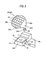
- Fig. 5 is a perspective view showing the diffusion lens.
- Fig. 6 is a diagram showing a structure of a dimming portion (a current control portion) of a light source unit.
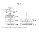
- Fig. 7 is a flowchart showing an operation of the dimming portion (the current control portion), and
- Fig. 8 is a view showing light distribution patterns formed by first, second and third light source units, (a) being a view showing a light distribution pattern for a low beam which is formed by the first and second light source units and (b) being a view showing a light distribution pattern for a high beam or a light distribution pattern for a DTL which is formed by the third light source unit.
- a headlamp 1 for a car has a structure in which a light source unit assembly 10 having three light source units 10A, 10B and 10C integrated with a lamp bracket 12 is accommodated in a lamp housing S formed by a lamp body 2 taking a shape of a container and a transparent front cover 4.
- the light source unit assembly 10 is supported tiltably in a vertical direction through an auto-leveling mechanism E (an aiming mechanism) which is provided between the lamp bracket 12 and the lamp body 2.
- the auto-leveling mechanism E includes a pair of left and right aiming screws 21a and 21b supported rotatably on front and rear insertion holes provided on a back wall of the lamp body 2, aiming nuts 22a and 22b attached to the lamp bracket 12 in a screwing configuration into the aiming screws 21a and 21b, a leveling actuator 28 attached to a position placed under the aiming screw 21a at an inside of the back wall of the lamp body 2 and including a rotating and driving shaft 21c extended in parallel with the aiming screws 21a and 21b, and an aiming nut 22c attached to the lamp bracket 12 in a screwing configuration into a tip screw portion of the rotating and driving shaft 21c.
- the auto-leveling mechanism E has a structure in which the light source unit assembly 10 (the lamp bracket 12) is tiltable around a leveling shaft Lx (a shaft passing through the nuts 22a and 22b) by a driving operation of the actuator 28 (a rotating operation of the rotating and driving shaft 21 c).
- the actuator 28 rotates the rotating and driving shaft 21c to move the aiming nut 22c forward and backward along the rotating and driving shaft 21c based on a signal sent from a center-of-gravity position detecting sensor (not shown) for detecting a movement in a longitudinal direction of a center-of-gravity position of a car, for example, and tilts the light source unit assembly 10 around the leveling shaft Lx to always maintain an optical axis of the headlamp 1 (the light source unit assembly 10) into a constant configuration with respect to a running road surface.
- a center-of-gravity position detecting sensor not shown
- the aiming screw 21b functions as a transverse aiming screw for tilting and adjusting the optical axis of the headlamp 1 around a vertical tilting axis Ly (an axis passing through the aiming nuts 22a and 22c), and the aiming screws 21a and 21 b also function as vertical aiming screws for tilting and adjusting the optical axis of the headlamp 1 around a virtual horizontal tilting axis passing through the aiming nut 22c. Therefore, the auto-leveling mechanism E also acts as an aiming mechanism.
- the first and second projection type light source units 10A and 10B for a low beam formation and the third reflection type light source unit 10C for a high beam formation are integrated apart from each other by predetermined distances in vertical and transverse directions at a front side of the lamp bracket 12 formed of a metal having a high thermal conductivity, for example, aluminum and taking an almost rectangular shape seen from a front.
- the projection type light source units 10A and 10B include light emitting devices 14a and 14b as light sources attached to an upper surface of a protruded portion 13 which has a rectangular shape and protrudes toward a front side of the bracket 12; reflectors 16a and 16b formed by a resin, having an almost ellipsoidal shape, and attached onto the forward protruded portion 13 to cover the light emitting devices 14a and 14b; a cutoff line forming shade 17 formed by a resin and attached to a tip part of the forward protruded portion 13 with a screw 13a; and a projection convex lens 18 formed by a resin and attached to a tip of a forward extended portion 17a of the shade 17, respectively.
- the reference numeral 13b denotes an opening portion formed behind the forward protruded portion 13 and the reference numeral 12a denotes a radiator fin provided in predetermined positions on front and back sides of the lamp bracket 12.
- the projection type light source units 10A and 10B have optical axes La and Lb which extend longitudinally.
- Reflecting surfaces 16a1 and 16b1 of the reflectors 16a and 16b have major axes which are coaxial with the optical axes La and Lb and include curved surfaces taking an almost ellipsoidal shape with light emitting centers of the light emitting devices 14a and 14b set to be first focal points.
- the shade 17 is extended forward in an almost horizontal direction in such a manner that an upper front edge part thereof is positioned in the vicinity of a rear focal point F of the projection lens 18, and the projection convex lens 18 disposed on each of the optical axes La and Lb with the rear focal point F set to be almost coincident with a second focal point of each of the reflecting surfaces 16a1 and 16b1 projects, as an inverted image, an image on a focal plane including the rear focal point F onto a virtual vertical screen in front of the headlamp and forms a light distribution pattern for a headlamp low beam having a predetermined clear cutoff line corresponding to a front edge of the shade 17 (see the reference numerals Psa and Psb in Fig. 8 ).
- the reflection type light source unit 10C includes a light distribution forming reflector 16c which is formed by a resin and has a reflecting surface 16c1 having a shape of a paraboloid, and is attached to an upper surface of a plate-shaped protruded portion 13A protruded toward the front side of the bracket 12, and a light emitting device 14c as a light source disposed on an almost focal position of the reflecting surface 16c1 of the reflector 16c, and forms a light distribution pattern for a headlamp high beam which is indicated as Pm in Fig. 8(b) .
- the reflection type light source unit 10C is provided with a diffusion lens 30 to contribute to form a light distribution for a day time running lamp (which will be hereinafter referred to as a DTL), and it is possible to switch a light distribution for the headlamp high beam and for the DTL by putting the diffusion lens 30 in/out from between the light emitting device 14c and the reflector 16c.
- a DTL day time running lamp
- the diffusion lens 30 includes a lens body 32 taking an almost spherical shape and having a surface on which a fish-eye convex step 33 is formed, and legs 32a1 and 32b1 are extended downward from left and right sidewalls 32a and 32b of the lens body 32, and the sidewalls 32a and 32b are pivotally supported on side surfaces of the protruded portion 13A of the bracket 12. Furthermore, the legs 32a1 and 32b1 are coupled to a sliding plunger 38 of a solenoid 36 (a diffusion lens driving actuator) attached to a lower surface of the protruded portion 13A.
- a fish-eye concave step may be formed on the surface of the lens body 32 in place of the fish-eye convex step 33.
- a horizontal pin 39 extended transversely is protruded from a tip part of the sliding plunger 38 which is subjected to a detention in a circumferential direction with respect to a solenoid body 37 and can carry out forward and backward moving operations, and is engaged with slots 34 and 34 formed on the legs 32a1 and 32b1 of the diffusion lens body 32 so that the diffusion lens 30 (the lens body 32) is smoothly rotated (rocked) around a pivotal support shaft Ax without an unsteadiness by the forward and backward moving operations of the sliding plunger 38.
- the reference numerals 41 and 42 denote first and second stopper portions for positioning the diffusion lens, the stopper portions being protruded from left and right side surfaces of the protruded portion 13A of the bracket 12, and the diffusion lens 30 (the lens body 32) abuts on either the stopper portion 41 or the stopper portion 42 and is thus positioned relative to the light emitting device 14c and the reflector 16c.
- the diffusion lens 30 is always biased in a counterclockwise direction in Fig. 3 to abut on the first stopper portion 41 by means of a spring member (not shown) provided between the pivotal support shaft Ax and the second stopper portion 42.
- the diffusion lens 30 is set to a non-embedded configuration in which the diffusion lens 30 is not embedded between the light emitting device 14c and the reflector 16c (i.e., a configuration in which the diffusion lens 30 is in a position in which the diffusion lens 30 is not positioned between the light emitting device 14c and the reflector 16c) and is held in a predetermined position in which a light distribution formed by the reflector 16c is not shielded as shown in Fig.
- the sliding plunger 38 is moved forward.
- the diffusion lens 30 is rotated (rocked) against a spring energizing force in a clockwise direction around the pivotal support shaft Ax in Fig. 4 to a position in which the diffusion lens 30 abuts on the stopper portion 42 by the forward moving operation of the sliding plunger 38.
- the diffusion lens 30 is held in an embedded configuration in which the diffusion lens 30 is moved to a position (is embedded) between the light emitting device 14c and the reflector 16c (i.e., a configuration in which the diffusion lens 30 is provided between the light emitting device 14c and the reflector 16c) as shown in Fig. 4 .
- the light source unit 10C When the light source unit 10C is turned ON in this state, the light emitted from the light emitting device 14c is diffused in a transmission through the diffusion lens 30, and is diffused in a reflection through the reflector 16c, resulting in a formation of a light distribution pattern of the DTL (see the reference numeral Pdt1 in Fig. 8(b) ) which is diffused into a wide range in vertical and transverse directions in front of the lighting device.
- the diffusion lens 30 and the sliding plunger 36 are retuned into original positions shown in Fig. 3 by the spring energizing force acting on the diffusion lens 30.
- a control panel 52 on a driver's seat of a car is provided with a mode change-over switch 56 for switching between a high beam mode of the headlamp and a DTL mode.
- a current control portion 102 is provided between the control panel 52 (i.e., the mode change-over switch 56) and the light source unit 10C (the light emitting device 14c) as shown in Fig. 6 .
- the current control portion 102 serves as dimming portion for controlling (ON/OFF) a driving operation of the solenoid 36 and controlling an increase/decrease in a current to be supplied to the light emitting device 14c of the reflection type light source unit 10C based on a signal (a signal indicating which mode is to be selected) sent from the control panel 52 (the mode change-over switch 56).
- the current control portion 102 includes a switching portion 202, a current setting portion 212, a resistor 206, an operational amplifier 210, a pulse width modulation (PWM) controller 208, a switching regulator 204, a diode 214, and a capacitor 216 as shown in Fig. 6 .
- PWM pulse width modulation
- the switching portion 202 includes a change-over switch 502 and a plurality of diodes 504, 506 and 508.
- the change-over switch 502 receives, from the control panel 52 (the mode change-over switch 56), an instruction indicating whether the light source unit 10C is to be turned ON, and switches whether a power output from a battery 60 is to be output to either a terminal (P) or a terminal (H) in response to the instruction.
- the terminal (P) is connected to the solenoid 36.
- the change-over switch 502 electrically connects the battery 60 to the terminal (H).
- the solenoid 36 is not connected to the battery 60 and the diffusion lens 30 holds a configuration shown in Fig. 3 (the configuration for a formation of the headlamp high beam).
- the change-over switch 502 electrically connects the battery 60 to the terminal (P). Consequently, power is supplied to the solenoid 36.
- the sliding plunger 38 is moved forward so that the diffusion lens 30 is moved from the position for formation of the headlamp high beam shown in Fig. 3 to the position for formation of a DTL beam shown in Fig. 4 .
- terminals (P) and (H) are electrically connected to respective anodes of the diodes 504 and 506.
- Respective cathodes of the diodes 504 and 506 are electrically connected to each other and are electrically connected to the switching regulator 204 and the current setting portion 212.
- An anode and a cathode of the diode 508 are electrically connected to the terminal (H) and the current setting portion 212, respectively.
- the diode 508 outputs a signal having an H level.
- the diode 508 outputs a signal having an L level. More specifically, the switching portion 202 transmits, to the current setting portion 212, an instruction indicating whether the light source unit 10C is to be set to either the headlamp high beam or the DTL.
- the current setting portion 212 sets a magnitude of a supply current based on the instruction received from the control panel 52 (the mode change-over switch 56) through the switching portion 202 and applies a voltage corresponding to the magnitude of the supply current thus set to a positive input of the operational amplifier 210.
- the resistor 206 is connected downstream of the light emitting device 14c and generates, on both terminals, a voltage corresponding to the magnitude of the current to be supplied to the light emitting device 14c. Moreover, the resistor 206 has one terminal which is grounded and has another terminal connected electrically to a negative input of the operational amplifier 210. Consequently, the resistor 206 applies, to the negative input of the operational amplifier 210, a voltage corresponding to the magnitude of the current to be supplied to the light emitting device 14c.
- the operational amplifier 210 compares the magnitude of the supply current which is set by the current setting portion 212 with that of the current supplied to the light emitting device 14c based on the voltages received by the positive and negative inputs respectively from the current setting portion 212 and the resistor 206, and gives a result of the comparison to the PWM controller 208.
- the PWM controller 208 sends, to the switching regulator 204, a pulse signal having a pulse width based on the result of the comparison.
- the PWM controller 208 modulates the pulse width depending on an output of the operational amplifier 210, thereby changing an output of the switching regulator 204 and causing the switching regulator 204 to output a supply current having the magnitude set by the current setting portion 212.
- the switching regulator 204 includes a transformer 602 and a switch 604.
- a primary coil of the transformer 602 receives a power from the battery 60 through the switching portion 202 and is grounded through the switch 604.
- a secondary coil of the transformer 602 is electrically connected to the light emitting device 14c through the diode 214 and supplies a current smoothed by the capacitor 216 to the light emitting device 14c.
- the switch 604 is an NMOS transistor connected in series to the primary coil of the transformer 602 and receives a pulse signal output from the PWM controller 208 at a gate terminal. For this reason, the switch 604 is repetitively turned ON/OFF in response to the pulse signal and defines a current flowing to the primary coil of the transformer 602. Consequently, the switch 604 changes the current flowing to the primary coil of the transformer 602 corresponding to a pulse width of the pulse signal.
- the secondary coil of the transformer 602 provides, to the light emitting device 14c, a supply current having a magnitude set by the current setting portion 212 depending on the pulse width of the pulse signal. Consequently, the switching regulator 204 supplies, to the light emitting device 14c, the supply current based on an instruction received from the control panel 52.
- Fig. 7 is a flowchart showing an example of an operation of the current control portion 102.
- the current control portion 102 decides whether the light source unit 10C is to be set to either the DTL mode or the headlamp high beam mode based on an instruction received from the control panel 52 (the mode change-over switch 56). At this time, the solenoid 36 is not conducted, and the diffusion lens 30 is forward energized and therefore is not provided between the light emitting device 14c and the reflector 16c as shown in Fig. 3 .
- the current control portion 102 provides power to the solenoid 36 at Operation 104. Consequently, the plunger 38 of the solenoid 36 is moved forward so that the diffusion lens 30 (the lens body 32) is rocked rearward up to a position in which the diffusion lens 30 abuts on the second stopper portion 42. Thus, there is set a configuration in which the diffusion lens 30 (the lens body 32) is provided between the light emitting device 14c and the reflector 16c (see Fig. 4 ).
- the current control portion 102 decreases the current to be supplied to the light emitting device 14c at Operation 106, and turns ON the light emitting device 14c (the light source unit 10C) as the DTL at Operation 108. More specifically, the light emitting device 14c (the light source unit 10C) is turned ON, resulting in a formation of a diffused light for the DTL having a low luminous flux density and an excellent visibility which is led into a wide range in the forward part of the lighting device.
- the current control portion 102 does not provide power to the solenoid 36 but a predetermined current for the headlamp high beam is supplied to the light emitting device 14c at Operation 109, and the light source unit 10C is turned ON at Operation 110. More specifically, in a state of non-conduction of the solenoid 36, the diffusion lens 30 (the lens body 32) remains biased in a configuration in which the diffusion lens 30 abuts on the first stopper portion 41 and the diffusion lens 30 (the lens body 32) is not provided between the light emitting device 14c and the reflector 16c (see Fig. 3 ). Therefore, the light emitting device 14c (the light source unit 10C) is turned ON, resulting in a formation of a light distribution for the headlamp high beam which has a high luminous flux density and an excellent visibility.
- Fig. 9 is a perspective view showing a diffusion lens to be a main part of a headlamp for a vehicle according to a second example of the invention.
- a diffusion step of the diffusion lens 30 is constituted by the fish-eye step 33 in the first example
- a diffusion step of a diffusion lens 30A according to the second example is constituted by a cylindrical step 33A extended transversely as shown.
- Fig. 10 is a longitudinal sectional view showing a third light source unit to be a main part of a headlamp for a vehicle according to a third example of the invention.
- a diffusion lens 30 is integrated with a tip part of a sliding plunger 38 of a solenoid 36 so that the diffusion lens 30 can be slid in a longitudinal direction integrally with a driving operation of the solenoid 36 (forward and backward moving operations of the sliding plunger 38) in the third example.
- the diffusion lens 30 is brought into a configuration in which the diffusion lens 30 is disposed behind a reflector 16c and is not embedded between a light emitting device 14c and the reflector 16c, as shown by a double-dot dash line of Fig. 10 .
- the diffusion lens 30 is brought into a configuration in which the diffusion lens 30 is embedded between the light emitting device 14c and the reflector 16c as shown by a solid line of Fig. 10 .
- the invention is not restricted thereto.
Applications Claiming Priority (1)
| Application Number | Priority Date | Filing Date | Title |
|---|---|---|---|
| JP2008181023A JP5177873B2 (ja) | 2008-07-11 | 2008-07-11 | 車両用灯具 |
Publications (2)
| Publication Number | Publication Date |
|---|---|
| EP2143994A1 true EP2143994A1 (de) | 2010-01-13 |
| EP2143994B1 EP2143994B1 (de) | 2011-05-04 |
Family
ID=41058529
Family Applications (1)
| Application Number | Title | Priority Date | Filing Date |
|---|---|---|---|
| EP09165188A Active EP2143994B1 (de) | 2008-07-11 | 2009-07-10 | Beleuchtungsvorrichtung für Fahrzeug |
Country Status (4)
| Country | Link |
|---|---|
| EP (1) | EP2143994B1 (de) |
| JP (1) | JP5177873B2 (de) |
| AT (1) | ATE508326T1 (de) |
| DE (1) | DE602009001220D1 (de) |
Cited By (23)
| Publication number | Priority date | Publication date | Assignee | Title |
|---|---|---|---|---|
| CN103185269A (zh) * | 2011-12-27 | 2013-07-03 | 市光工业株式会社 | 车辆用前照灯 |
| WO2014147195A1 (fr) | 2013-03-21 | 2014-09-25 | Valeo Vision | Module d'éclairage et/ou de signalisation pour véhicule automobile |
| US8864350B2 (en) | 2011-07-26 | 2014-10-21 | Ichikoh Industries, Ltd. | Vehicle headlamp |
| EP2846081A1 (de) * | 2013-09-09 | 2015-03-11 | Valeo Vision | Vorrichtung zur Beleuchtung und Signalisierung für Fahrzeuge |
| US9121562B2 (en) | 2011-07-26 | 2015-09-01 | Ichikoh Industries, Ltd. | Vehicle headlamp |
| FR3022323A1 (fr) * | 2014-06-16 | 2015-12-18 | Valeo Vision | Module d'eclairage et/ou de signalisation rotatif |
| FR3022322A1 (fr) * | 2014-06-16 | 2015-12-18 | Valeo Vision | Module d'eclairage et/ou de signalisation rotatif |
| WO2016030598A1 (fr) * | 2014-08-27 | 2016-03-03 | Peugeot Citroen Automobiles Sa | Dispositif d'éclairage à équipage déplaçable et à réflecteur rotatif, pour un bloc optique de véhicule |
| FR3025862A1 (fr) * | 2014-09-16 | 2016-03-18 | Peugeot Citroen Automobiles Sa | Dispositif d'eclairage rotatif a lentille a position relative variable par rapport au reflecteur, pour un bloc optique de vehicule |
| EP2623850A4 (de) * | 2010-09-28 | 2016-03-30 | Koito Mfg Co Ltd | Stromkreismodul, lichtemissionsmodul und fahrzeuglampe |
| EP2375142A3 (de) * | 2010-04-12 | 2016-05-18 | Ichikoh Industries, Ltd. | Fahrzeugscheinwerfer |
| CN106287482A (zh) * | 2015-06-02 | 2017-01-04 | 堤维西交通工业股份有限公司 | 远近灯切换装置 |
| CN106704944A (zh) * | 2015-05-20 | 2017-05-24 | 古德里奇照明系统有限责任公司 | 动态飞机外部灯单元以及操作动态飞机外部灯单元的方法 |
| EP2610546A3 (de) * | 2011-12-27 | 2017-11-15 | Ichikoh Industries, Ltd. | Fahrzeugscheinwerfer |
| EP2610545A3 (de) * | 2011-12-27 | 2017-11-15 | Ichikoh Industries, Ltd. | Fahrzeugscheinwerfer |
| EP2610548A3 (de) * | 2011-12-27 | 2017-11-15 | Ichikoh Industries, Ltd. | Fahrzeugscheinwerfer |
| EP3379139A4 (de) * | 2015-11-20 | 2019-07-31 | Koito Manufacturing Co., Ltd. | Lampenfassung |
| DE102019111480A1 (de) * | 2019-05-03 | 2020-11-05 | Bayerische Motoren Werke Aktiengesellschaft | Beleuchtungseinrichtung für ein Kraftfahrzeug sowie Kraftfahrzeug mit Beleuchtungseinrichtung |
| EP3152480B1 (de) * | 2014-06-03 | 2021-02-24 | PSA Automobiles SA | Beleuchtungsvorrichtung mit beweglicher linse für kraftfahrzeug |
| WO2021170400A1 (fr) * | 2020-02-27 | 2021-09-02 | Valeo Vision | Module lumineux de véhicule automobile comprenant un dispositif électrochromique |
| FR3107749A1 (fr) * | 2020-02-27 | 2021-09-03 | Valeo Vision | Module lumineux de véhicule automobile comprenant un dispositif électrochromique |
| FR3107750A1 (fr) * | 2020-02-27 | 2021-09-03 | Valeo Vision | Module lumineux de véhicule automobile comprenant un dispositif électrochromique |
| FR3121084A1 (fr) * | 2021-03-29 | 2022-09-30 | Valeo Vision | Dispositif lumineux comprenant un système optique mobile. |
Families Citing this family (10)
| Publication number | Priority date | Publication date | Assignee | Title |
|---|---|---|---|---|
| JP2012069409A (ja) * | 2010-09-24 | 2012-04-05 | Panasonic Corp | 照明器具 |
| JP5659835B2 (ja) * | 2011-02-08 | 2015-01-28 | スタンレー電気株式会社 | 車両用灯具 |
| CN102691976B (zh) * | 2011-03-25 | 2013-11-13 | 海洋王照明科技股份有限公司 | 一种调光灯具 |
| JP6028480B2 (ja) * | 2012-09-14 | 2016-11-16 | 市光工業株式会社 | 車両用前照灯 |
| JP6175892B2 (ja) * | 2013-05-17 | 2017-08-09 | 市光工業株式会社 | 車両用前照灯 |
| JP6101587B2 (ja) * | 2013-07-18 | 2017-03-22 | 株式会社小糸製作所 | 車両用前照灯 |
| FR3009367B1 (fr) * | 2013-08-05 | 2018-06-15 | Valeo Vision | Dispositif optique et systeme de signalisation et/ou d'eclairage |
| KR102326051B1 (ko) * | 2014-12-04 | 2021-11-15 | 현대모비스 주식회사 | 자동차의 조명장치 |
| KR102361316B1 (ko) * | 2015-04-08 | 2022-02-09 | 제트카베 그룹 게엠베하 | 차량용 램프 및 이를 포함하는 차량 |
| JP7011901B2 (ja) * | 2017-06-27 | 2022-02-10 | コイト電工株式会社 | 制御装置及び点灯システム |
Citations (2)
| Publication number | Priority date | Publication date | Assignee | Title |
|---|---|---|---|---|
| DE102004002280A1 (de) * | 2004-01-16 | 2005-08-25 | Automotive Lighting Reutlingen Gmbh | Scheinwerferanordnung |
| FR2882589A1 (fr) * | 2005-02-28 | 2006-09-01 | Valeo Vision Sa | Dispositif d'eclairage ou de signalisation perfectionne pour vehicule automobile |
Family Cites Families (3)
| Publication number | Priority date | Publication date | Assignee | Title |
|---|---|---|---|---|
| JPH0247060Y2 (de) * | 1986-07-31 | 1990-12-11 | ||
| JP2003127760A (ja) * | 2001-10-30 | 2003-05-08 | Koito Mfg Co Ltd | 自動車用ヘッドランプ |
| JP2004276740A (ja) * | 2003-03-14 | 2004-10-07 | Koito Mfg Co Ltd | 車両用灯具 |
-
2008
- 2008-07-11 JP JP2008181023A patent/JP5177873B2/ja not_active Expired - Fee Related
-
2009
- 2009-07-10 DE DE602009001220T patent/DE602009001220D1/de active Active
- 2009-07-10 AT AT09165188T patent/ATE508326T1/de not_active IP Right Cessation
- 2009-07-10 EP EP09165188A patent/EP2143994B1/de active Active
Patent Citations (2)
| Publication number | Priority date | Publication date | Assignee | Title |
|---|---|---|---|---|
| DE102004002280A1 (de) * | 2004-01-16 | 2005-08-25 | Automotive Lighting Reutlingen Gmbh | Scheinwerferanordnung |
| FR2882589A1 (fr) * | 2005-02-28 | 2006-09-01 | Valeo Vision Sa | Dispositif d'eclairage ou de signalisation perfectionne pour vehicule automobile |
Cited By (32)
| Publication number | Priority date | Publication date | Assignee | Title |
|---|---|---|---|---|
| EP2375142A3 (de) * | 2010-04-12 | 2016-05-18 | Ichikoh Industries, Ltd. | Fahrzeugscheinwerfer |
| EP2623850A4 (de) * | 2010-09-28 | 2016-03-30 | Koito Mfg Co Ltd | Stromkreismodul, lichtemissionsmodul und fahrzeuglampe |
| US9121562B2 (en) | 2011-07-26 | 2015-09-01 | Ichikoh Industries, Ltd. | Vehicle headlamp |
| US8864350B2 (en) | 2011-07-26 | 2014-10-21 | Ichikoh Industries, Ltd. | Vehicle headlamp |
| EP2610546A3 (de) * | 2011-12-27 | 2017-11-15 | Ichikoh Industries, Ltd. | Fahrzeugscheinwerfer |
| CN103185269A (zh) * | 2011-12-27 | 2013-07-03 | 市光工业株式会社 | 车辆用前照灯 |
| EP2610548A3 (de) * | 2011-12-27 | 2017-11-15 | Ichikoh Industries, Ltd. | Fahrzeugscheinwerfer |
| EP2610547A3 (de) * | 2011-12-27 | 2017-11-15 | Ichikoh Industries, Ltd. | Fahrzeugscheinwerfer |
| EP2610545A3 (de) * | 2011-12-27 | 2017-11-15 | Ichikoh Industries, Ltd. | Fahrzeugscheinwerfer |
| WO2014147195A1 (fr) | 2013-03-21 | 2014-09-25 | Valeo Vision | Module d'éclairage et/ou de signalisation pour véhicule automobile |
| FR3010485A1 (fr) * | 2013-09-09 | 2015-03-13 | Valeo Vision | Dispositif d'eclairage et de signalisation d'un vehicule |
| EP2846081A1 (de) * | 2013-09-09 | 2015-03-11 | Valeo Vision | Vorrichtung zur Beleuchtung und Signalisierung für Fahrzeuge |
| EP3152480B1 (de) * | 2014-06-03 | 2021-02-24 | PSA Automobiles SA | Beleuchtungsvorrichtung mit beweglicher linse für kraftfahrzeug |
| FR3022323A1 (fr) * | 2014-06-16 | 2015-12-18 | Valeo Vision | Module d'eclairage et/ou de signalisation rotatif |
| EP2957821A1 (de) * | 2014-06-16 | 2015-12-23 | Valeo Vision | Drehbares beleuchtungs- und/oder signalisierungsmodul |
| CN105180047A (zh) * | 2014-06-16 | 2015-12-23 | 法雷奥照明公司 | 旋转的照明和/或信号指示模块 |
| FR3022322A1 (fr) * | 2014-06-16 | 2015-12-18 | Valeo Vision | Module d'eclairage et/ou de signalisation rotatif |
| CN106796007A (zh) * | 2014-08-27 | 2017-05-31 | 标致·雪铁龙汽车公司 | 用于车辆光学单元的具有可移动构件和可旋转反射器的照明装置 |
| FR3025283A1 (fr) * | 2014-08-27 | 2016-03-04 | Peugeot Citroen Automobiles Sa | Dispositif d'eclairage a equipage deplacable et a reflecteur rotatif, pour un bloc optique de vehicule |
| WO2016030598A1 (fr) * | 2014-08-27 | 2016-03-03 | Peugeot Citroen Automobiles Sa | Dispositif d'éclairage à équipage déplaçable et à réflecteur rotatif, pour un bloc optique de véhicule |
| WO2016042226A1 (fr) * | 2014-09-16 | 2016-03-24 | Peugeot Citroen Automobiles Sa | Dispositif d'éclairage rotatif à lentille à position relative variable par rapport au réflecteur, pour un bloc optique de véhicule |
| FR3025862A1 (fr) * | 2014-09-16 | 2016-03-18 | Peugeot Citroen Automobiles Sa | Dispositif d'eclairage rotatif a lentille a position relative variable par rapport au reflecteur, pour un bloc optique de vehicule |
| CN106704944A (zh) * | 2015-05-20 | 2017-05-24 | 古德里奇照明系统有限责任公司 | 动态飞机外部灯单元以及操作动态飞机外部灯单元的方法 |
| CN106287482A (zh) * | 2015-06-02 | 2017-01-04 | 堤维西交通工业股份有限公司 | 远近灯切换装置 |
| US10845021B2 (en) | 2015-11-20 | 2020-11-24 | Koito Manufacturing Co., Ltd. | Lamp unit |
| EP3379139A4 (de) * | 2015-11-20 | 2019-07-31 | Koito Manufacturing Co., Ltd. | Lampenfassung |
| DE102019111480A1 (de) * | 2019-05-03 | 2020-11-05 | Bayerische Motoren Werke Aktiengesellschaft | Beleuchtungseinrichtung für ein Kraftfahrzeug sowie Kraftfahrzeug mit Beleuchtungseinrichtung |
| WO2021170400A1 (fr) * | 2020-02-27 | 2021-09-02 | Valeo Vision | Module lumineux de véhicule automobile comprenant un dispositif électrochromique |
| FR3107749A1 (fr) * | 2020-02-27 | 2021-09-03 | Valeo Vision | Module lumineux de véhicule automobile comprenant un dispositif électrochromique |
| FR3107750A1 (fr) * | 2020-02-27 | 2021-09-03 | Valeo Vision | Module lumineux de véhicule automobile comprenant un dispositif électrochromique |
| US11841122B2 (en) | 2020-02-27 | 2023-12-12 | Valeo Vision | Motor vehicle light module comprising an electrochromic device |
| FR3121084A1 (fr) * | 2021-03-29 | 2022-09-30 | Valeo Vision | Dispositif lumineux comprenant un système optique mobile. |
Also Published As
| Publication number | Publication date |
|---|---|
| EP2143994B1 (de) | 2011-05-04 |
| DE602009001220D1 (de) | 2011-06-16 |
| JP5177873B2 (ja) | 2013-04-10 |
| JP2010018178A (ja) | 2010-01-28 |
| ATE508326T1 (de) | 2011-05-15 |
Similar Documents
| Publication | Publication Date | Title |
|---|---|---|
| EP2143994B1 (de) | Beleuchtungsvorrichtung für Fahrzeug | |
| US9956901B2 (en) | Automotive headlamp apparatus having swivel function of lamp unit | |
| US9648679B2 (en) | Vehicle lamp and lighting circuit thereof | |
| EP2275305B1 (de) | Automobilscheinwerfervorrichtung | |
| JP4400884B2 (ja) | 車輌用灯具 | |
| JP4995748B2 (ja) | 車両用前照灯装置及び車両用前照灯装置の制御方法 | |
| US10081294B2 (en) | Lighting apparatus for a vehicle | |
| US8172442B2 (en) | Vehicle lamp | |
| US20070041207A1 (en) | Vehicle lamp | |
| JP5828424B2 (ja) | 車輌用前照灯 | |
| US6161950A (en) | Vehicle headlamp having a leveling unit | |
| JP2006315512A (ja) | 車輌用灯具 | |
| JP2007001427A (ja) | 車輌用灯具 | |
| EP2266837B1 (de) | System zur Steuerung der Lichtverteilung von Fahrzeugscheinwerfer | |
| JP2008296660A (ja) | 車両用前照灯 | |
| JPWO2014033834A1 (ja) | 前照灯用光源および前照灯 | |
| EP2543927B1 (de) | Fahrzeugscheinwerfer | |
| US6513958B2 (en) | Vehicle lamp system | |
| EP2100771B1 (de) | Fahrzeugscheinwerfervorrichtung und Verfahren zu deren Steuerung | |
| US6152584A (en) | Vehicle headlight | |
| EP2384931A2 (de) | Steuervorrichtung, Fahrzeuglampensystem und Fahrzeuglampe | |
| CN212226934U (zh) | 车辆用灯具 | |
| JP5055650B2 (ja) | プロジェクタ型前照灯 | |
| JP2012226997A (ja) | 車輌用前照灯 | |
| JP4386017B2 (ja) | 車両用前照灯 |
Legal Events
| Date | Code | Title | Description |
|---|---|---|---|
| PUAI | Public reference made under article 153(3) epc to a published international application that has entered the european phase |
Free format text: ORIGINAL CODE: 0009012 |
|
| 17P | Request for examination filed |
Effective date: 20090710 |
|
| AK | Designated contracting states |
Kind code of ref document: A1 Designated state(s): AT BE BG CH CY CZ DE DK EE ES FI FR GB GR HR HU IE IS IT LI LT LU LV MC MK MT NL NO PL PT RO SE SI SK SM TR |
|
| GRAP | Despatch of communication of intention to grant a patent |
Free format text: ORIGINAL CODE: EPIDOSNIGR1 |
|
| RIC1 | Information provided on ipc code assigned before grant |
Ipc: F21V 14/06 20060101AFI20100929BHEP |
|
| GRAC | Information related to communication of intention to grant a patent modified |
Free format text: ORIGINAL CODE: EPIDOSCIGR1 |
|
| GRAS | Grant fee paid |
Free format text: ORIGINAL CODE: EPIDOSNIGR3 |
|
| GRAA | (expected) grant |
Free format text: ORIGINAL CODE: 0009210 |
|
| AK | Designated contracting states |
Kind code of ref document: B1 Designated state(s): AT BE BG CH CY CZ DE DK EE ES FI FR GB GR HR HU IE IS IT LI LT LU LV MC MK MT NL NO PL PT RO SE SI SK SM TR |
|
| REG | Reference to a national code |
Ref country code: GB Ref legal event code: FG4D |
|
| REG | Reference to a national code |
Ref country code: CH Ref legal event code: EP |
|
| REG | Reference to a national code |
Ref country code: IE Ref legal event code: FG4D |
|
| REF | Corresponds to: |
Ref document number: 602009001220 Country of ref document: DE Date of ref document: 20110616 Kind code of ref document: P |
|
| REG | Reference to a national code |
Ref country code: DE Ref legal event code: R096 Ref document number: 602009001220 Country of ref document: DE Effective date: 20110616 |
|
| REG | Reference to a national code |
Ref country code: NL Ref legal event code: VDEP Effective date: 20110504 |
|
| PG25 | Lapsed in a contracting state [announced via postgrant information from national office to epo] |
Ref country code: PT Free format text: LAPSE BECAUSE OF FAILURE TO SUBMIT A TRANSLATION OF THE DESCRIPTION OR TO PAY THE FEE WITHIN THE PRESCRIBED TIME-LIMIT Effective date: 20110905 Ref country code: LT Free format text: LAPSE BECAUSE OF FAILURE TO SUBMIT A TRANSLATION OF THE DESCRIPTION OR TO PAY THE FEE WITHIN THE PRESCRIBED TIME-LIMIT Effective date: 20110504 Ref country code: SE Free format text: LAPSE BECAUSE OF FAILURE TO SUBMIT A TRANSLATION OF THE DESCRIPTION OR TO PAY THE FEE WITHIN THE PRESCRIBED TIME-LIMIT Effective date: 20110504 Ref country code: NO Free format text: LAPSE BECAUSE OF FAILURE TO SUBMIT A TRANSLATION OF THE DESCRIPTION OR TO PAY THE FEE WITHIN THE PRESCRIBED TIME-LIMIT Effective date: 20110804 |
|
| PG25 | Lapsed in a contracting state [announced via postgrant information from national office to epo] |
Ref country code: SI Free format text: LAPSE BECAUSE OF FAILURE TO SUBMIT A TRANSLATION OF THE DESCRIPTION OR TO PAY THE FEE WITHIN THE PRESCRIBED TIME-LIMIT Effective date: 20110504 Ref country code: BE Free format text: LAPSE BECAUSE OF FAILURE TO SUBMIT A TRANSLATION OF THE DESCRIPTION OR TO PAY THE FEE WITHIN THE PRESCRIBED TIME-LIMIT Effective date: 20110504 Ref country code: FI Free format text: LAPSE BECAUSE OF FAILURE TO SUBMIT A TRANSLATION OF THE DESCRIPTION OR TO PAY THE FEE WITHIN THE PRESCRIBED TIME-LIMIT Effective date: 20110504 Ref country code: IS Free format text: LAPSE BECAUSE OF FAILURE TO SUBMIT A TRANSLATION OF THE DESCRIPTION OR TO PAY THE FEE WITHIN THE PRESCRIBED TIME-LIMIT Effective date: 20110904 Ref country code: GR Free format text: LAPSE BECAUSE OF FAILURE TO SUBMIT A TRANSLATION OF THE DESCRIPTION OR TO PAY THE FEE WITHIN THE PRESCRIBED TIME-LIMIT Effective date: 20110805 Ref country code: AT Free format text: LAPSE BECAUSE OF FAILURE TO SUBMIT A TRANSLATION OF THE DESCRIPTION OR TO PAY THE FEE WITHIN THE PRESCRIBED TIME-LIMIT Effective date: 20110504 Ref country code: CY Free format text: LAPSE BECAUSE OF FAILURE TO SUBMIT A TRANSLATION OF THE DESCRIPTION OR TO PAY THE FEE WITHIN THE PRESCRIBED TIME-LIMIT Effective date: 20110504 Ref country code: LV Free format text: LAPSE BECAUSE OF FAILURE TO SUBMIT A TRANSLATION OF THE DESCRIPTION OR TO PAY THE FEE WITHIN THE PRESCRIBED TIME-LIMIT Effective date: 20110504 Ref country code: ES Free format text: LAPSE BECAUSE OF FAILURE TO SUBMIT A TRANSLATION OF THE DESCRIPTION OR TO PAY THE FEE WITHIN THE PRESCRIBED TIME-LIMIT Effective date: 20110815 |
|
| PG25 | Lapsed in a contracting state [announced via postgrant information from national office to epo] |
Ref country code: MT Free format text: LAPSE BECAUSE OF FAILURE TO SUBMIT A TRANSLATION OF THE DESCRIPTION OR TO PAY THE FEE WITHIN THE PRESCRIBED TIME-LIMIT Effective date: 20110504 Ref country code: NL Free format text: LAPSE BECAUSE OF FAILURE TO SUBMIT A TRANSLATION OF THE DESCRIPTION OR TO PAY THE FEE WITHIN THE PRESCRIBED TIME-LIMIT Effective date: 20110504 |
|
| PG25 | Lapsed in a contracting state [announced via postgrant information from national office to epo] |
Ref country code: CZ Free format text: LAPSE BECAUSE OF FAILURE TO SUBMIT A TRANSLATION OF THE DESCRIPTION OR TO PAY THE FEE WITHIN THE PRESCRIBED TIME-LIMIT Effective date: 20110504 Ref country code: EE Free format text: LAPSE BECAUSE OF FAILURE TO SUBMIT A TRANSLATION OF THE DESCRIPTION OR TO PAY THE FEE WITHIN THE PRESCRIBED TIME-LIMIT Effective date: 20110504 |
|
| PG25 | Lapsed in a contracting state [announced via postgrant information from national office to epo] |
Ref country code: PL Free format text: LAPSE BECAUSE OF FAILURE TO SUBMIT A TRANSLATION OF THE DESCRIPTION OR TO PAY THE FEE WITHIN THE PRESCRIBED TIME-LIMIT Effective date: 20110504 Ref country code: MC Free format text: LAPSE BECAUSE OF NON-PAYMENT OF DUE FEES Effective date: 20110731 Ref country code: SK Free format text: LAPSE BECAUSE OF FAILURE TO SUBMIT A TRANSLATION OF THE DESCRIPTION OR TO PAY THE FEE WITHIN THE PRESCRIBED TIME-LIMIT Effective date: 20110504 |
|
| PLBE | No opposition filed within time limit |
Free format text: ORIGINAL CODE: 0009261 |
|
| STAA | Information on the status of an ep patent application or granted ep patent |
Free format text: STATUS: NO OPPOSITION FILED WITHIN TIME LIMIT |
|
| 26N | No opposition filed |
Effective date: 20120207 |
|
| REG | Reference to a national code |
Ref country code: IE Ref legal event code: MM4A |
|
| PG25 | Lapsed in a contracting state [announced via postgrant information from national office to epo] |
Ref country code: HR Free format text: LAPSE BECAUSE OF FAILURE TO SUBMIT A TRANSLATION OF THE DESCRIPTION OR TO PAY THE FEE WITHIN THE PRESCRIBED TIME-LIMIT Effective date: 20111123 Ref country code: IT Free format text: LAPSE BECAUSE OF FAILURE TO SUBMIT A TRANSLATION OF THE DESCRIPTION OR TO PAY THE FEE WITHIN THE PRESCRIBED TIME-LIMIT Effective date: 20110504 |
|
| REG | Reference to a national code |
Ref country code: DE Ref legal event code: R097 Ref document number: 602009001220 Country of ref document: DE Effective date: 20120207 |
|
| PG25 | Lapsed in a contracting state [announced via postgrant information from national office to epo] |
Ref country code: IE Free format text: LAPSE BECAUSE OF NON-PAYMENT OF DUE FEES Effective date: 20110710 |
|
| PG25 | Lapsed in a contracting state [announced via postgrant information from national office to epo] |
Ref country code: MK Free format text: LAPSE BECAUSE OF FAILURE TO SUBMIT A TRANSLATION OF THE DESCRIPTION OR TO PAY THE FEE WITHIN THE PRESCRIBED TIME-LIMIT Effective date: 20110504 |
|
| PG25 | Lapsed in a contracting state [announced via postgrant information from national office to epo] |
Ref country code: SM Free format text: LAPSE BECAUSE OF FAILURE TO SUBMIT A TRANSLATION OF THE DESCRIPTION OR TO PAY THE FEE WITHIN THE PRESCRIBED TIME-LIMIT Effective date: 20110504 |
|
| PG25 | Lapsed in a contracting state [announced via postgrant information from national office to epo] |
Ref country code: LU Free format text: LAPSE BECAUSE OF NON-PAYMENT OF DUE FEES Effective date: 20110710 |
|
| PG25 | Lapsed in a contracting state [announced via postgrant information from national office to epo] |
Ref country code: BG Free format text: LAPSE BECAUSE OF FAILURE TO SUBMIT A TRANSLATION OF THE DESCRIPTION OR TO PAY THE FEE WITHIN THE PRESCRIBED TIME-LIMIT Effective date: 20110804 |
|
| PG25 | Lapsed in a contracting state [announced via postgrant information from national office to epo] |
Ref country code: TR Free format text: LAPSE BECAUSE OF FAILURE TO SUBMIT A TRANSLATION OF THE DESCRIPTION OR TO PAY THE FEE WITHIN THE PRESCRIBED TIME-LIMIT Effective date: 20110504 |
|
| PG25 | Lapsed in a contracting state [announced via postgrant information from national office to epo] |
Ref country code: HU Free format text: LAPSE BECAUSE OF FAILURE TO SUBMIT A TRANSLATION OF THE DESCRIPTION OR TO PAY THE FEE WITHIN THE PRESCRIBED TIME-LIMIT Effective date: 20110504 |
|
| PG25 | Lapsed in a contracting state [announced via postgrant information from national office to epo] |
Ref country code: HR Free format text: LAPSE BECAUSE OF FAILURE TO SUBMIT A TRANSLATION OF THE DESCRIPTION OR TO PAY THE FEE WITHIN THE PRESCRIBED TIME-LIMIT Effective date: 20110504 |
|
| REG | Reference to a national code |
Ref country code: CH Ref legal event code: PL |
|
| PG25 | Lapsed in a contracting state [announced via postgrant information from national office to epo] |
Ref country code: LI Free format text: LAPSE BECAUSE OF NON-PAYMENT OF DUE FEES Effective date: 20130731 Ref country code: CH Free format text: LAPSE BECAUSE OF NON-PAYMENT OF DUE FEES Effective date: 20130731 |
|
| REG | Reference to a national code |
Ref country code: FR Ref legal event code: PLFP Year of fee payment: 7 |
|
| PGFP | Annual fee paid to national office [announced via postgrant information from national office to epo] |
Ref country code: DE Payment date: 20150707 Year of fee payment: 7 Ref country code: GB Payment date: 20150708 Year of fee payment: 7 |
|
| PGFP | Annual fee paid to national office [announced via postgrant information from national office to epo] |
Ref country code: FR Payment date: 20150629 Year of fee payment: 7 |
|
| REG | Reference to a national code |
Ref country code: DE Ref legal event code: R119 Ref document number: 602009001220 Country of ref document: DE |
|
| GBPC | Gb: european patent ceased through non-payment of renewal fee |
Effective date: 20160710 |
|
| PG25 | Lapsed in a contracting state [announced via postgrant information from national office to epo] |
Ref country code: FR Free format text: LAPSE BECAUSE OF NON-PAYMENT OF DUE FEES Effective date: 20160801 Ref country code: DE Free format text: LAPSE BECAUSE OF NON-PAYMENT OF DUE FEES Effective date: 20170201 |
|
| REG | Reference to a national code |
Ref country code: FR Ref legal event code: ST Effective date: 20170331 |
|
| PG25 | Lapsed in a contracting state [announced via postgrant information from national office to epo] |
Ref country code: GB Free format text: LAPSE BECAUSE OF NON-PAYMENT OF DUE FEES Effective date: 20160710 |