EP2141979B2 - Transportwagen für insbesondere landwirtschaftliches stückgut - Google Patents
Transportwagen für insbesondere landwirtschaftliches stückgut Download PDFInfo
- Publication number
- EP2141979B2 EP2141979B2 EP08749297.1A EP08749297A EP2141979B2 EP 2141979 B2 EP2141979 B2 EP 2141979B2 EP 08749297 A EP08749297 A EP 08749297A EP 2141979 B2 EP2141979 B2 EP 2141979B2
- Authority
- EP
- European Patent Office
- Prior art keywords
- transport wagon
- wagon according
- cargo
- transport
- longitudinal
- Prior art date
- Legal status (The legal status is an assumption and is not a legal conclusion. Google has not performed a legal analysis and makes no representation as to the accuracy of the status listed.)
- Active
Links
Images


Classifications
-
- B—PERFORMING OPERATIONS; TRANSPORTING
- B60—VEHICLES IN GENERAL
- B60P—VEHICLES ADAPTED FOR LOAD TRANSPORTATION OR TO TRANSPORT, TO CARRY, OR TO COMPRISE SPECIAL LOADS OR OBJECTS
- B60P7/00—Securing or covering of load on vehicles
- B60P7/06—Securing of load
- B60P7/135—Securing or supporting by load bracing means
-
- A—HUMAN NECESSITIES
- A01—AGRICULTURE; FORESTRY; ANIMAL HUSBANDRY; HUNTING; TRAPPING; FISHING
- A01D—HARVESTING; MOWING
- A01D90/00—Vehicles for carrying harvested crops with means for selfloading or unloading
- A01D90/02—Loading means
- A01D90/08—Loading means with bale-forming means additionally used for loading; with means for picking-up bales and transporting them into the vehicle
- A01D90/083—Round-bale trailers
-
- B—PERFORMING OPERATIONS; TRANSPORTING
- B60—VEHICLES IN GENERAL
- B60J—WINDOWS, WINDSCREENS, NON-FIXED ROOFS, DOORS, OR SIMILAR DEVICES FOR VEHICLES; REMOVABLE EXTERNAL PROTECTIVE COVERINGS SPECIALLY ADAPTED FOR VEHICLES
- B60J5/00—Doors
- B60J5/04—Doors arranged at the vehicle sides
- B60J5/0497—Doors arranged at the vehicle sides for load transporting vehicles or public transport, e.g. lorries, trucks, buses
-
- B—PERFORMING OPERATIONS; TRANSPORTING
- B62—LAND VEHICLES FOR TRAVELLING OTHERWISE THAN ON RAILS
- B62D—MOTOR VEHICLES; TRAILERS
- B62D33/00—Superstructures for load-carrying vehicles
- B62D33/02—Platforms; Open load compartments
- B62D33/023—Sideboard or tailgate structures
- B62D33/027—Sideboard or tailgate structures movable
- B62D33/03—Sideboard or tailgate structures movable by swinging down
Definitions
- the invention relates to a trolley for general cargo according to the preamble of claim 1, such trolleys except for general cargo from agricultural crop, especially in the form of pressed round bales, even for pressed paper waste, plastic bales o. The like. Recyclables are used.
- a transport system for present in round or cuboid form pressed bales, which consist of pressed roughage o. Like. Harvest.
- pressed bales which consist of pressed roughage o. Like. Harvest.
- bale receiving boxes On a dolly a variety of bale receiving boxes is provided, which receive the round bales in an orderly structure.
- the round bales are on the one hand transportable and on the other hand, the system is designed so that the boxes connected to a container can also be used to store the round bales until their intended use.
- a transport vehicle designed as a collecting vehicle which has a rear-side receiving device for the piece goods, from which the parts designed in particular as silage bales are displaceable on a loading platform delimited by stationary side walls, a special roller conveyor being provided for this displacement in the region of the loading platform.
- a foldable side board for trucks according to EP 0 043 178 the wall consisting of at least two plate parts is horizontally divided in the region of a joint.
- the foldable displacement of these plate parts is controlled by a guided in a vertical rod shear joint and a fixed in the region of the loading platform provided hinge.
- a similar construction is in GB 1 244 778 proposed, wherein the two hinged plate parts are pivotally held in the region of a near the loading platform extending, fixed to the vehicle shaft.
- US 2,496,388 a transport vehicle for tree trunks is shown, wherein a loading and unloading device is pivotally supported on the chassis. To secure the tree trunks two support arms are attached to the side of the loading platform.
- a truck according to DE-A-18 02 040 are provided liftable and lowerable side walls. These side walls interact with a supporting device so that the area of the loading area can be closed to the side. Thus, the side walls can be applied to the loading platform side walls form a tightly sealable container system.
- US-A-6,152,511 shows a trolley, in which the side wall parts provided above respective side support beams are each designed as a pivotable about a horizontal support axis in an open and a closed position Schwencklappen per se known design.
- the invention is concerned with the problem of creating a trolley for agricultural parcels, whereby a maximizable in volume to adapt to regulations of road transport volume is receivable, so high transport services are possible and in the loading platform with a little effort to different load conditions adaptable load securing is reachable.
- the transport carriage provided with side walls which can be displaced in the open position has, in the design according to the invention, an improved supporting device in the area of at least one of the longitudinal side walls, with which a multi-layer stacking piece goods can be detected by the longitudinal side wall in such a way that an additional lateral clamping fixation is achieved is.
- an improved supporting device in the area of at least one of the longitudinal side walls, with which a multi-layer stacking piece goods can be detected by the longitudinal side wall in such a way that an additional lateral clamping fixation is achieved is.
- both connected to the at least one support device longitudinal side walls by a synchronous movement in the manner of a clamping gate on the cargo can be applied.
- this pressing or clamping position only a portion of the side surfaces of the multilayer stack good is detected on the loading wagon.
- a free space is created laterally in the lower area between the clamping gate and the loading platform, in which parts of the cargo stack are open and accessible from the side.
- additional securing elements are provided in the region of the free space.
- flexible clamping parts are provided as securing elements, which are moved in displacement of the clamping gate in the upper closed position and are largely completely laterally applied to the stacked cargo.
- an additional backup is achieved for the lower layers of the piece goods.
- the securing elements it is also possible to make a projecting over the constructive width of the loading platform loading of the trolley, so that for example two parallel to the longitudinal center plane of the trolley parallel stack of round bales o. The like.
- Packages are transported and the lateral securing elements a shift From piece goods from one of the stack across the direction of travel reliably prevent even when cornering.
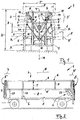
- Fig. 1 is a total of 1 designated dolly for agricultural parcels shown.
- the cargo On its loading platform 5, the cargo in the form of from straw, silage o. The like. Crop pressed round bales 2 ( Fig. 3 ).
- the trolley 1 in this case has one in several layers L, L 'stacked for transport cargo 2 under cross and of longitudinal and transverse side parts 3, 3'; 4, 4 'limited loading platform 5 on.
- the defined above the loading platform 5 transport space is accessible in known trolley 1 in that its longitudinal side walls (similar to the walls 3, 3 ') are laterally hinged (similar to position A, dashed line according to Fig. 1 or arrow G according to Fig. 9 ).
- the transport carriage 1 is provided in the region of at least one of the longitudinal side walls 3, 3 '(in the illustrated embodiments in the case of both walls 3, 3') with a support device S, by means of which the longitudinal side walls 3, 3 'starting from an open position A (during loading ) in at least one upper layer L ( Fig. 3 ) of the stacked piece goods 2 detecting and thus laterally locking closed position ( Fig. 2 to 4 Position B) are displaceable (on a trajectory according to dash-dot line R, Fig. 1 . Fig. 9 ).
- a weight-optimized narrow design (width dimension: T, Fig. 2 ) of the longitudinal side walls 3, 3 'in lightweight construction with few components provides that these lattice-like walls by means of the support device S are substantially completely below a plane E of the loading platform 5 next to the trolley 1 lowered and from this lowered position A are so harnessschwenkbar that only the uppermost layer L of the multi-layer piece goods 2 in the illustrated closed position ( Fig. 2 to 4 ) is detected directly by the narrow grid construction (in the area T).
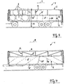
- FIG. 2 to 4 illustrate this combination, wherein as the support device S, S 'cooperate two at each one end of the longitudinal side wall 3, 3' attacking assemblies. These are supported in particular in the region of the respective transverse side wall 4, 4 '( Fig. 2 ). It is conceivable that these assemblies of the support device S, S 'are manually operated. As appropriate, it has been found, however, generally provided with 7, 7 'designated drive members on at least one of the modules.
- a swivel-clamping system is formed in the region of the longitudinal side walls 3, 3 ', in which the walls 3, 3' provided with torsionally rigid rod elements 8, 8 'and 9 are constructed according to Art of respective clamping gates K, K 'become effective (arrow F, Fig. 1 ).
- These clamping gates K, K ' have at the other end in the region of the load-bearing assemblies of the support device S respective connecting joints 12 and 13, wherein a generally designated 11 support rods are provided with respective effective as Lenkparallelogramm links 19, 20.
- these longitudinal side walls 3, 3 ' are each preferably provided at the lower edge of the clamping gate K, K' in the region of their horizontal bar 8 'with the securing elements 6 extending to the edge region of the loading platform 5 ( Fig. 2 to 4 ).
- the clamping gates K, K ' are from the ground-level loading position (lowered position A, Fig. 1 ) by means of one of the towing vehicle (not shown) operated, provided as a drive member 7 hydraulic drive 15 in a respective preselectable investment position on cargo 2 harnessschwenkbar.
- the respective securing elements 6 can be moved so that the multi-layer stacked on the loading platform 5 cargo 2, in particular in the form of round bales, is secured transportable in all layers.
- the drive concept 7 can be designed so that the clamping grille K, K 'and the securing element 6 by means of at least one support device S together are continuously adjustable.
- the securing elements 6 are provided in particular in the form of flexible clamping parts.
- Fig. 4 are illustrated with 24 foldable profile parts and with 25 telescopic or foldable elements as further conceivable designs. It is also conceivable that the spent in clamping position securing elements 6 are subsequently adjustable by hand.
- the securing elements 6 can also be individually or jointly adjustable by means of a drive, not shown.
- FIG. 1 illustrates that the two as support device S, S 'cooperating component groups respective support rods 11 which are arranged substantially mirror-inverted to the longitudinal center plane M of the trolley 1.
- a support rod 11 while a respective parallelogram-forming arm 19, 20 are provided and each of these pairs is associated with a hydraulic cylinder 15 as the drive member 7.
- the support rods 11 each have a vertically extending in the longitudinal center plane M and on the parts of the transverse side walls 4, 4 'held support beam 26, at the corresponding height distance D, D' both the two links 19, 20 and the hydraulic drive member pivotally held at respective joints represented by points.
- This support system is designed so that on an optimal trajectory R displaced components cause a reliable clamping bracket of the piece goods 2.
- the traversed by the two clamping gates K, K 'by means of the supporting devices S, S' trajectory R is illustrated with a curved line.
- An arrow H indicates a measure of a conceivable maximum loading height (eg 4 m) of the loading wagon 1.
- the wagon 1 When the wagon 1 is empty, the wagon 1 has a width P (for example 2.55 m) which corresponds to the traffic regulations and when loaded the system can have a loading width P '(eg 3 m), so that in the direction of travel on both sides of the longitudinal center plane M in each case a stacking of correspondingly long piece goods 2, 2 'and 2 "( Fig. 6 . Fig. 8 ) is possible.
- the embodiment of the securing element 6 ' is shown as a side wall which can be displaced independently of the gate K, K' and which is in the direction of the arrow G ( Fig. 9 ) is pivotable about a corresponding joint 27.
- the securing element 6 ' can be operated by hand and fixed in the closed position by a connector.
- the securing element 6 ' is formed from a plurality of wall elements 29 separated in the longitudinal direction.
- the one length 30 and a usable space 31 ( Fig. 7 ) transporting trolleys 1 can, in addition to the transport of bales 2, 2 'having different dimensions, also receive cuboidal parts such as pressed bales 2 ", crates or pallets, as well as receiving bales of garbage, straw pellets, pressed sawdust, peat bales and packages in sack form , Paper bales or the like transportable conceivable a multi-layer stacking of the piece goods 2 "( Fig. 7 , different hatching) shows the effect of the clamping gate K in the region of the upper layers and the lower layers are detected by the respective securing element 6, 6 '. This ensures that even trolley 1 with a partially filled receiving space, for example, only a lower layer and a few piece goods in the second position, is sufficiently safe to use for road transport and loss-free transport.
Landscapes
- Engineering & Computer Science (AREA)
- Mechanical Engineering (AREA)
- Transportation (AREA)
- Chemical & Material Sciences (AREA)
- Combustion & Propulsion (AREA)
- Life Sciences & Earth Sciences (AREA)
- Environmental Sciences (AREA)
- Loading Or Unloading Of Vehicles (AREA)
- Handcart (AREA)
Description
- Die Erfindung betrifft einen Transportwagen für Stückgut gemäß dem Oberbegriff des Anspruchs 1, wobei derartige Transportwagen außer für Stückgut aus landwirtschaftlichem Erntegut, insbesondere in Form von gepreßten Rundballen, auch für gepreßten Papierabfall, Kunststoffballen o. dgl. Wertstoffe einsetzbar sind.
- Gemäß
DE 33 12 585 A1 ist ein Transportsystem für in runder oder quaderförmiger Form vorliegende Preßballen vorgesehen, die aus gepreßtem Rauhfutter o. dgl. Erntegut bestehen. Auf einem Transportwagen ist dabei eine Vielzahl von Ballenaufnahmeboxen vorgesehen, die die Rundballen in geordneter Struktur aufnehmen. In diesen Boxen sind die Rundballen einerseits transportierbar und andererseits ist das System so ausgelegt, daß die zu einem Container verbundenen Boxen auch zur Aufbewahrung der Rundballen bis zu deren bestimmungsmäßigen Gebrauch nutzbar sind. - In
DE 200 22 895 ist ein als Sammelfahrzeug ausgebildeter Transportwagen vorgesehen, der eine heckseitige Aufnahmevorrichtung für das Stückgut aufweist, von der aus die insbesondere als Silageballen ausgebildeten Teile auf eine durch ortsfeste Seitenwände begrenzte Ladeplattform verlagerbar sind, wobei für diese Verlagerung im Bereich der Ladeplattform eine spezielle Rollenbahn vorgesehen ist. Mit diesen zusätzlichen Bauteilen ist der nutzbare Transportraum nachteilig eingeschränkt. - Bei einer faltbaren Seitenbordwand für Lastfahrzeuge gemäß
EP 0 043 178 ist die aus zumindest zwei Plattenteilen bestehende Wand im Bereich eines Gelenkes horizontal geteilt. Die faltbare Verlagerung dieser Plattenteile wird durch ein in einer Vertikalstange geführtes Schubgelenk und ein ortsfest im Bereich der Ladeplattform vorgesehenes Scharnier gesteuert. Eine ähnliche Konstruktion ist inGB 1 244 778 US 2,496,388 ist ein Transportfahrzeug für Baumstämme gezeigt, wobei eine Be- und Entladevorrichtung schwenkbar am Fahrgestell gehalten ist. Zur Sicherung der Baumstämme werden seitlich an der Ladeplattform zwei Stützarme angebracht. - Bei einem Lastfahrzeug gemäß
DE-A-18 02 040 sind hebe- und senkbare Bordwände vorgesehen. Diese Bordwände wirken mit einer Stützvorrichtung so zusammen, dass der Bereich der Ladefläche zur Seite hin zugemacht werden kann. Damit bilden die seitlich an die Ladefläche anlegbaren Bordwände ein dicht verschließbares Behälter-System. - Die Konstruktion gemäß
US-A-6,152,511 zeigt einen Transportwagen, bei dem die oberhalb jeweiliger seitlicher Stützbalken vorgesehenen Seitenwandteile jeweils als um eine horizontale Stützachse in eine Offnungs- und eine Schließstellung verlagerbare Schwencklappen an sich bekannter Gestaltung ausgebildet sind. - Die Erfindung befaßt sich mit dem Problem, einen Transportwagen für landwirtschaftliches Stückgut zu schaffen, womit ein in Anpassung an Vorschriften des Straßenverkehrs maximierbares Stückgut-Volumen aufnehmbar ist, damit hohe Transportleistungen möglich sind und im Bereich der Ladeplattform eine mit geringem Aufwand an unterschiedliche Beladezustände anpaßbare Ladungssicherung erreichbar ist.
- Die Erfindung löst diese Aufgabe durch einen Transportwagen mit den Merkmalen des Anspruchs 1. Weitere vorteilhafte Ausgestaltungen ergeben sich aus den Ansprüchen 2 bis 17.
- Der mit in Öffnungsstellung verlagerbaren Seitenwänden versehene Transportwagen weist in erfindungsgemäßer Ausführung im Bereich zumindest einer der Längsseitenwände eine verbesserte Stützvorrichtung auf, mit deren einen Antrieb aufweisenden Hubgestänge das eine mehrlagige Stapelung bildende Stückgut von der Längsseitenwand so erfaßbar ist, daß eine zusätzliche seitliche Klemm-Fixierung erreicht ist. Durch eine variabel steuerbare Schwenk-Hub-Bewegung kann insbesondere die obere Lage des Stapels positionsgenau erfaßt und seitlich gepreßt werden, so daß damit bei einer für den Straßenverkehr zulässigen maximalen Ladungshöhe auf der Ladeplattform eine größere Stabilität der Stapelung erreicht ist und Gefährdungen sowie Ladungsverluste vermeidbar sind.
- Insbesondere sind beide mit der zumindest einen Stützvorrichtung verbundene Längsseitenwände durch eine synchrone Bewegung nach Art eines Klemmgatters an den Stückgütern anlegbar. In dieser Preß- bzw. Klemmlage wird jeweils nur ein Teilbereich der Seitenflächen des mehrlagigen Stapelgutes auf dem Ladewagen erfaßt. In einer oberen Anlagestellung entsteht seitlich im unteren Bereich zwischen Klemmgatter und Ladeplattform ein Freiraum, in dem Teile der Stückgut-Stapel offen und seitlich zugänglich sind. In erfindungsgemäßer Weiterbildung der Klemm-Konstruktion mit den Klemmgattern sind im Bereich des Freiraumes zusätzliche Sicherungselemente vorgesehen. Diese können in zweckmäßiger Ausführung mit den Längsseitenwänden bzw. deren Stützvorrichtung(en) zusammenwirken.
- Als Sicherungselemente sind dabei insbesondere flexible Spannteile vorgesehen, die bei Verlagerung des Klemmgatters in die obere Schließposition mitbewegt werden und dabei weitgehend vollständig seitlich an das gestapelte Stückgut anlegbar sind. Damit ist für die unteren Lagen des Stückgutes eine zusätzliche Sicherung erreicht. Mit dieser Ausführung der Sicherungselemente ist es möglich, auch eine über die konstruktiv vorgegebene Breite der Ladeplattform vorstehende Beladung des Transportwagens vorzunehmen, so daß beispielsweise zwei zur Längsmittelebene des Transportwagens parallel aufliegende Stapel von Rundballen o. dgl. Stückgut transportierbar sind und die seitlichen Sicherungselemente eine Verschiebung von Stückgut aus einem der Stapel quer zur Fahrtrichtung auch bei Kurvenfahrten zuverlässig verhindern.
- Weitere Einzelheiten und vorteilhafte Ausgestaltungen der Erfindung ergeben sich aus der Zeichnung, in der zwei Ausführungsbeispiele des erfindungsgemäßen Transportwagens dargestellt sind. In der Zeichnung zeigen:
- Fig. 1
- eine Rückansicht des erfindungsgemäßen Transportwagens mit in einer oberen Schließstellung befindlichen Längsseitenwänden,
- Fig. 2
- eine Seitenansicht des Transportwagens gemäß
Fig. 1 , - Fig. 3
- eine Seitenansicht einer zweiten Ausführung des Transportwagens mit verlagerbaren Seitenwänden,
- Fig. 4
- eine Seitenansicht ähnlich
Fig. 3 mit einer dritten Ausführung des Transportwagens, - Fig. 5
- eine Seitenansicht ähnlich
Fig. 3 mit einem als Bordwand ausgebildeten Sicherungselement, - Fig. 6
- eine Rückansicht des beladenen Transportwagens gemäß
Fig. 6 , - Fig. 7
- eine Seitenansicht ähnlich
Fig. 5 mit quaderförmigem Stückgut auf der Ladepfattform, - Fig. 8
- eine Seitenansicht ähnlich
Fig. 7 mit einer in Längsrichtung mehrteiligen Ausführung der Bordwand, und - Fig. 9
- eine Rückansicht des Transportwagens gemäß
Fig. 8 . - In
Fig. 1 ist ein insgesamt mit 1 bezeichneter Transportwagen für landwirtschaftliches Stückgut dargestellt. Auf dessen Ladeplattform 5 kann das Stückgut in Form von aus Stroh, Silage o. dgl. Erntegut gepreßten Rundballen 2 (Fig. 3 ) aufgenommen werden. Der Transportwagen 1 weist dabei eine das in mehreren Lagen L, L' zum Transport gestapelte Stückgut 2 untergreifenden und von Längs- sowie Querseitenteilen 3, 3'; 4, 4' begrenzte Ladeplattform 5 auf. Der über der Ladeplattform 5 definierte Transportraum ist bei an sich bekannten Transportwagen 1 dadurch zugänglich, daß dessen Längsseitenwände (ähnlich den Wänden 3, 3') seitlich abklappbar sind (ähnlich Position A, Strichdarstellung gemäßFig. 1 bzw. Pfeil G gemäßFig. 9 ). - Erfindungsgemäß ist der Transportwagen 1 im Bereich zumindest einer der Längsseitenwände 3, 3' (in den dargestellten Ausführungen bei beiden Wänden 3, 3') mit einer Stützvorrichtung S versehen, mittels der die Längsseitenwände 3, 3' ausgehend von einer Öffnungsstellung A (beim Beladen) in eine zumindest eine obere Lage L (
Fig. 3 ) des gestapelten Stückgutes 2 erfassende und dieses damit seitlich sichernde Schließstellung (Fig. 2 bis 4 : Stellung B) verlagerbar sind (auf einer Bewegungsbahn gemäß Strich-Punkt-Linie R,Fig. 1 ,Fig. 9 ). - Eine gewichtsoptimale schmale Ausführung (Breitenmaß: T,
Fig. 2 ) der Längsseitenwände 3, 3' in Leichtbauweise mit wenigen Bauteilen sieht vor, daß diese gitterartigen Wände mittels der Stützvorrichtung S weitgehend vollständig bis unterhalb einer Ebene E der Ladeplattform 5 neben den Transportwagen 1 absenkbar sind und aus dieser Absenkstellung A so hochschwenkbar sind, daß nur die oberste Lage L des mehrlagigen Stückgutes 2 in der dargestellten Schließstellung (Fig. 2 bis 4 ) von der schmalen Gitterkonstruktion (im Bereich T) direkt erfaßt wird. - Bei diesen Längsseitenwänden 3, 3' ergibt sich jedoch, daß eine Zone Z unterhalb der Längsseitenwände 3, 3' in der Schließstellung "frei bleibt", so daß in diesem Bereich die Gefahr besteht, daß das in einer unteren oder mittleren Lage L' befindliche Stückgut (
Fig. 3 ), beispielsweise bei einer Kurvenfahrt, seitlich herausrutschen kann. Deshalb sieht das erfindungsgemäße Konzept mit auf der Bahn R schwenkbaren Längsseitenwänden 3, 3' auch vor, daß unterhalb der Längsseitenwände 3, 3' jeweils ein zumindest bei mehrlagigem Stückgut L, L' die untere Lage L' zusätzlich erfassendes, allgemein mit 6 bezeichnetes Sicherungselement vorgesehen wird (Fig. 2 ). - Die Seitenansichten gemäß
Fig. 2 bis 4 verdeutlichen diese Kombination, wobei als die Stützvorrichtung S, S' zwei an jeweils einem Ende der Längsseitenwand 3, 3' angreifende Baugruppen zusammenwirken. Diese sind insbesondere im Bereich der jeweiligen Querseitenwand 4, 4' abgestützt (Fig. 2 ). Denkbar ist, daß diese Baugruppen der Stützvorrichtung S, S' von Hand bedienbar sind. Als zweckmäßig hat es sich jedoch erwiesen, allgemein mit 7, 7' bezeichnete Antriebsorgane an zumindest einer der Baugruppen vorzusehen. - Mit dieser funktionalen Bauteilverbindung S, S' und 7, 7' wird im Bereich der Längsseitenwände 3, 3' ein Schwenk-Klemm-System gebildet, bei dem die mit verwindungssteifen Stangenelementen 8, 8' und 9 versehenen Wände 3, 3' nach Art von jeweiligen Klemmgattern K, K' wirksam werden (Pfeil F,
Fig. 1 ). Diese Klemmgatter K, K' weisen anderenends im Bereich der tragenden Baugruppen der Stützvorrichtung S jeweilige Verbindungsgelenke 12 und 13 auf, wobei ein allgemein mit 11 bezeichnetes Traggestänge mit jeweiligen als Lenkparallelogramm wirksamen Lenkern 19, 20 versehen sind. - Es versteht sich dabei, daß diese Längsseitenwände 3, 3' jeweils vorzugsweise am unteren Rand des Klemmgatters K, K' im Bereich ihrer horizontalen Stange 8' mit den zum Randbereich der Ladeplattform 5 verlaufenden Sicherungselementen 6 versehen sind (
Fig. 2 bis 4 ). - Die Klemmgatter K, K' sind dabei aus der bodennahen Beladestellung (Absenkstellung A,
Fig. 1 ) mittels eines vom Zugfahrzeug (nicht dargestellt) betätigten, als Antriebsorgan 7 vorgesehenen Hydraulikantriebes 15 in eine jeweils vorwählbare Anlagestellung am Stückgut 2 hochschwenkbar. Dabei können die jeweiligen Sicherungselemente 6 so mitbewegt werden, daß das mehrlagig auf der Ladeplattform 5 gestapelte Stückgut 2, insbesondere in Form von Rundballen, in sämtlichen Lagen transportgerecht gesichert wird. Das Antriebskonzept 7 kann dabei so ausgelegt werden, daß die Klemmgitter K, K' und das Sicherungselement 6 mittels der zumindest einen Stützvorrichtung S gemeinsam stufenlos verstellbar sind. - Die Sicherungselemente 6 sind dabei insbesondere in Form von flexiblen Spannteilen vorgesehen. Beispielhaft sind dabei Planen, Seile 21 (
Fig. 3 ), Gurte 22 (Fig. 2 ) oder Netze 23 (Fig. 2 ) dargestellt. InFig. 4 sind mit 24 klappbare Profilteile und mit 25 teleskopierbare bzw. faltbare Elemente als weitere denkbare Ausführungen verdeutlicht. Ebenso ist denkbar, daß die in Spannstellung verbrachten Sicherungselemente 6 nachträglich von Hand einstellbar sind. Die Sicherungselemente 6 können dabei auch mittels eines nicht näher dargestellten Antriebes einzeln oder gemeinsam verstellbar sein. - Die Stirnansicht gemäß
Fig. 1 verdeutlicht, daß die beiden als Stützvorrichtung S, S' zusammenwirkenden Bauteilgruppen jeweilige Traggestänge 11 aufweisen, die im wesentlichen spiegelbildlich zur Längsmittelebene M des Transportwagens 1 angeordnet sind. Als Traggestänge 11 sind dabei die jeweils ein Parallelogramm bildenden Lenker 19, 20 vorgesehen und jedem dieser Paare ist ein Hydraulikzylinder 15 als das Antriebsorgan 7 zugeordnet. Die Traggestänge 11 weisen dabei jeweils einen vertikal in der Längsmittelebene M verlaufenden und an den Teilen der Querseitenwände 4, 4' gehaltenen Stützbalken 26 auf, an dem mit entsprechendem Höhenabstand D, D' sowohl die beiden Lenker 19, 20 als auch das hydraulische Antriebsorgan 7 schwenkbar an jeweiligen durch Punkte dargestellten Gelenken gehalten sind. Dieses Stützsystem ist dabei so konzipiert, daß auf einer optimalen Bewegungsbahn R verlagerte Bauteile eine zuverlässige Klemmhalterung des Stückgutes 2 bewirken. - Die von den beiden Klemmgattern K, K' mittels der Stützvorrichtungen S, S' durchlaufene Bewegungsbahn R ist mit einer Bogenlinie verdeutlicht. Mit einem Pfeil H wird ein Maß für eine denkbare maximale Ladehöhe (z. B. 4 m) des Ladewagens 1 angedeutet. Bei einer Leerfahrt des Ladewagens 1 weist dieser eine den Vorschriften des Straßenverkehrs entsprechende Breite P (z. B. 2,55 m) auf und in beladenem Zustand kann das System eine Ladebreite P' (z. B. 3 m) aufweisen, so daß in Fahrtrichtung beidseits der Längsmittelebene M jeweils eine Stapelung von entsprechend langen Stückgütern 2, 2' und 2" (
Fig. 6 ,Fig. 8 ) möglich ist. - In
Fig. 5 ist die Ausführung des Sicherungselementes 6' als eine unabhängig vom Gatter K, K' verlagerbare Bordwand dargestellt, die in Pfeilrichtung G (Fig. 9 ) um ein entsprechendes Gelenk 27 schwenkbar ist. Diese Bordwand-Sicherung 6' kann dabei als ein Rohrrahmen 28 ausgeführt sein, der von Hand bzw. durch einen Antrieb, einen Kraftspeicher o. dgl. Hilfsmittel (nicht dargestellt) verlagerbar sein kann. Im einfachsten Fall ist das Sicherungselement 6' von Hand bedienbar und in der Schließstellung durch einen Verbinder fixierbar. In der Ausführung gemäßFig. 8 ist das Sicherungselement 6' aus mehreren in Längsrichtung getrennten Wandelementen 29 gebildet. - Der eine Länge 30 und eine Nutzraumlänge 31 (
Fig. 7 ) aufweisende Transportwagen 1 kann neben dem Transport von unterschiedliche Abmessungen aufweisenden Ballen 2, 2' als Stückgut auch quaderförmige Teile wie Preßbatlen 2", Kisten oder Paletten gesichert aufnehmen. Ebenso ist die Aufnahme von Müllballen, Strohpelletts, gepreßten Sägespänen, Torfballen, Gebinden in Sackform, Papierballen o. dgl. Transportgut denkbar. Eine mehrlagige Stapelung des Stückgutes 2" (Fig. 7 , unterschiedliche Schraffur) zeigt die Wirkung des Klemmgatters K im Bereich der oberen Lagen und die unteren Lagen werden durch das jeweilige Sicherungselement 6, 6' erfaßt. Damit ist gewährleistet, daß auch Transportwagen 1 mit einem nur teilweise gefüllten Aufnahmeraum, beispielsweise nur eine untere Lage und wenigen Stückgütern in der zweiten Lage, für den Straßenverkehr und einen verlustfreien Transport hinreichend sicher einsetzbar ist.
Claims (17)
- Transportwagen für Stückgut (2), insbesondere aus landwirtschaftlichem Erntegut wie Stroh oder Silage gepreßten Ballen, mit einer das Stückgut (2) untergreifenden und von Längs- sowie Querseitenteilen (3, 3'; 4, 4') begrenzten Ladeplattform (5), wobei deren Transportraum insbesondere bei geöffneten und mittels einer Stützvorrichtung (S, S') in eine bodennahe Öffnungsstellung (A) abgesenkten Längsseitenwänden (3, 3') zugänglich ist, dadurch gekennzeichnet, daß die zumindest eine mit der Stützvorrichtung (S, S') verlagerbare Längsseitenwand (3, 3') in eine eine Ladehöhe (H) oberhalb der Ladeplattform (5) definierende, zu dieser einen als freie Zone (Z) einen Abstand aufweisende, zumindest eine obere Lage (L) des gestapelten Stückgutes (2, 2', 2") erfassende und dieses seitlich als ein Schwenk-Klemm-System sichernde (Pfeil F) Schließstellung (B) hochschwenkbar (Pfeil R) ist, wobei mit dem einen Antrieb (7, 7') aufweisenden Hubgestänge der Stützvorrichtung (S, S') das eine mehrlagige Stapelung bildende Stückgut (2, 2', 2") von der Längsseitenwand (3, 3') so erfassbar ist, dass eine seitliche Klemm-Fixierung erreicht ist.
- Transportwagen nach Anspruch 1, dadurch gekennzeichnet, daß zumindest eine der Längsseitenwände (3, 3') mittels der Stützvorrichtung (S, S') weitgehend vollständig bis unterhalb der Ebene (E) der Ladeplattform (5) neben diese absenkbar ist und aus einer Absenkstellung (A) in eine nur die oberste Lage (L) des mehrlagigen Stückgutes (2, 2', 2") erfassende Schließstellung hochschwenkbar (Linie R) ist.
- Transportwagen nach Anspruch 1 oder 2, dadurch gekennzeichnet, daß die Längsseitenwand (3, 3') mit zumindest einem bei mehrlagigem Stückgut (2, 2', 2") die untere(n) Lage(n) (L') zusätzlich sichernden Sicherungselement (6, 6') zusammenwirkt.
- Transportwagen nach einem der Ansprüche 1 bis 3, dadurch gekennzeichnet, daß als die Stützvorrichtung (S, S') zwei an jeweils einem Ende der Längsseitenwand (3, 3') angreifende Baugruppen zusammenwirken und diese im Bereich der jeweiligen Querseitenwand (4, 4') abgestützt sind.
- Transportwagen nach Anspruch 3 oder 4 nur wenn abhängig von Anspruch 3, dadurch gekennzeichnet, daß das Sicherungselement (6, 6') von Hand oder mittels zumindest eines Antriebsorgans (7) bedienbar ist.
- Transportwagen nach einem der Ansprüche 1 bis 5, dadurch gekennzeichnet, daß als Längsseitenwände (3, 3') jeweilige mit verwindungssteifen Stangenelementen (8, 8', 9) ausgebildete Klemmgatter (K, K') vorgesehen sind und diese im Bereich der endseitigen Stützvorrichtung (S, S') ein jeweiliges Traggestänge (11) aufweisen.
- Transportwagen nach den Ansprüchen 6 und 3, dadurch gekennzeichnet, daß die Längsseitenwände (3, 3') jeweils am unteren Rand des Klemmgatters (K, K') das zum Randbereich der Ladeplattform (5) verlaufende Sicherungselement (6) aufweisen.
- Transportwagen nach einem der Ansprüche 6 bis 7 und 3, dadurch gekennzeichnet, daß das Klemmgatter (K, K') aus der bodennahen Beladestellung (A) mittels eines Hydraulikantriebes (15) in einstellbare Anlagestellungen am Stückgut (2) hochschwenkbar, dabei das Sicherungselement (6) mitbewegbar und so das mehrlagig (L, L') auf der Ladeplattform (5) gestapelte Stückgut (2), insbesondere in Form von Rundballen, transportgerecht gesichert ist.
- Transportwagen nach einem der Ansprüche 6 bis 8 und 3, dadurch gekennzeichnet, daß das Klemmgatter (K, K') und das Sicherungselement (6) mittels der Stützvorrichtung (S, S') stufenlos verstellbar sind, derart, daß die jeweilige Anlagestellung an entsprechend der Größe des Stückgutes (2) variierende Klemmbedingungen anpaßbar ist.
- Transportwagen nach einem der Ansprüche 3 bis 9 nur wenn abhängig von Anspruch 3, dadurch gekennzeichnet, daß das Sicherungselement (6) aus flexiblen Spannteilen wie Planen, Seile (21), Gurte (22), Netze (23) o. dgl. gebildet ist.
- Transportwagen nach einem der Ansprüche 3 bis 10 nur wenn abhängig von Anspruch 3, dadurch gekennzeichnet, daß das Sicherungselement (6) von Hand einstellbar und fixierbar ist.
- Transportwagen nach einem der Ansprüche 3 bis 11 nur wenn abhängig von Anspruch 3, dadurch gekennzeichnet, daß das Sicherungselement (6) mittels eines Antriebs verstellbar ist.
- Transportwagen nach einem der Ansprüche 6 bis 12 und 3, dadurch gekennzeichnet, daß das Sicherungselement (6') als eine unabhängig vom Klemmgatter (K, K') verlagerbare Bordwand ausgebildet ist.
- Transportwagen nach Anspruch 13, dadurch gekennzeichnet, daß die Bordwand (6') von Hand klappbar ist.
- Transportwagen nach einem der Ansprüche 6 bis 14 nur wenn abhängig von Anspruch 6, dadurch gekennzeichnet, daß die beiden als Stützvorrichtung (S, S') zusammenwirkenden Traggestänge (11) im Wesentlichen spiegelbildlich zur Längsmittelebene (M) des Transportwagens (1) angeordnete Bauteile aufweisen.
- Transportwagen nach den Ansprüchen 15 und 5, dadurch gekennzeichnet, daß als Traggestänge (11) jeweils zwei ein Parallelogramm bildende Führungsstreben (19, 20) vorgesehen sind und jedem Paar der Führungsstreben (19, 20) ein Hydraulikzylinder (15) als das Antriebsorgan (7) zugeordnet ist.
- Transportwagen nach Anspruch 16, dadurch gekennzeichnet, daß die Traggestänge (11) jeweils mit einem vertikal in der Längsmittelebene (M) verlaufenden Stützbalken (26) versehen sind, an dem mit entsprechendem Höhenabstand (D, D') sowohl die beiden Führungsstreben (19, 20) als auch das Antriebsorgan (7) schwenkbar gehalten sind.
Priority Applications (1)
| Application Number | Priority Date | Filing Date | Title |
|---|---|---|---|
| PL08749297T PL2141979T5 (pl) | 2007-05-03 | 2008-05-02 | Przyczepa transportowa zwłaszcza dla rolniczego ładunku drobnicowego |
Applications Claiming Priority (2)
| Application Number | Priority Date | Filing Date | Title |
|---|---|---|---|
| DE102007020735A DE102007020735A1 (de) | 2007-05-03 | 2007-05-03 | Transportwagen für insbesondere landwirtschaftliches Stückgut |
| PCT/EP2008/003551 WO2008135236A1 (de) | 2007-05-03 | 2008-05-02 | Transportwagen für insbesondere landwirtschaftliches stückgut |
Publications (3)
| Publication Number | Publication Date |
|---|---|
| EP2141979A1 EP2141979A1 (de) | 2010-01-13 |
| EP2141979B1 EP2141979B1 (de) | 2014-06-04 |
| EP2141979B2 true EP2141979B2 (de) | 2019-08-14 |
Family
ID=39680998
Family Applications (1)
| Application Number | Title | Priority Date | Filing Date |
|---|---|---|---|
| EP08749297.1A Active EP2141979B2 (de) | 2007-05-03 | 2008-05-02 | Transportwagen für insbesondere landwirtschaftliches stückgut |
Country Status (7)
| Country | Link |
|---|---|
| US (1) | US8523502B2 (de) |
| EP (1) | EP2141979B2 (de) |
| CA (1) | CA2686032C (de) |
| DE (1) | DE102007020735A1 (de) |
| DK (1) | DK2141979T4 (de) |
| PL (1) | PL2141979T5 (de) |
| WO (1) | WO2008135236A1 (de) |
Families Citing this family (16)
| Publication number | Priority date | Publication date | Assignee | Title |
|---|---|---|---|---|
| US20140271093A1 (en) * | 2013-03-14 | 2014-09-18 | Poet Research, Inc. | Self-strapping round bale trailer |
| DE202013005936U1 (de) | 2013-07-02 | 2013-08-07 | Torsten Hundertmark | Ladungssicherungssytem für Ballenwagen |
| DE202013105357U1 (de) | 2013-11-25 | 2014-01-30 | Matthias Überdiek | Sicherungsvorrichtung für ein Lastfahrzeug |
| DE202015005847U1 (de) | 2015-06-08 | 2015-09-23 | Johann Demmler Kg | Ladungssicherungsvorrichtung für landwirtschaftliche Transportwagen |
| US9931973B2 (en) * | 2016-07-26 | 2018-04-03 | Brad VanBochove | Hay bale transport device |
| DE202016004557U1 (de) | 2016-07-26 | 2016-10-20 | Johann Demmler Kg | Ladungssicherungs-Abdeckvorrichtung für landwirtschaftliche Transportwagen |
| EP3326861B1 (de) | 2016-11-23 | 2020-07-15 | H.P. Beck & Söhne AG | Ladungssicherungsvorrichtung |
| DE102018105704B4 (de) * | 2018-03-13 | 2021-04-15 | Heiko Plaschna | Bewegliche Absicherung einer Ladefläche bei Transportvorrichtungen |
| CA3099844A1 (en) * | 2018-05-10 | 2019-11-14 | Malone Farm Machinery Limited | A bale transporter and a method for transporting bales |
| DE202019100403U1 (de) | 2019-01-24 | 2020-04-27 | Oehler Maschinen Fahrzeugbau GmbH | System zum Aufnehmen, Wechseln und Lagern von Sicherungseinheiten zum Sichern von auf einem Transportanhänger gelagerten Gegenständen sowie Transportanhänger zum Transportieren von derartigen Gegenständen |
| DE102020132067B3 (de) | 2020-12-02 | 2022-04-21 | Oehler Maschinen Fahrzeugbau GmbH | Transportanhänger zum Transportieren von Gegenständen |
| FR3120283B1 (fr) * | 2021-03-04 | 2023-07-07 | Soc Ind Dapplications Mec | Plateau fourrager |
| CN214929282U (zh) * | 2021-06-18 | 2021-11-30 | 河南跃薪智能机械有限公司 | 一种双源无轨式无人驾驶纯电动矿卡 |
| CN215552827U (zh) * | 2021-06-22 | 2022-01-18 | 河南跃薪智能机械有限公司 | 一种绿色矿山智能排运用砂石转运装置 |
| DE202021003877U1 (de) | 2021-12-27 | 2022-02-10 | Johann Demmler KG, Fahrzeugbau, Transportunternehmen Inh. Johann Demmler jun. e. K. | Ladungssicherungsvorrichtung für landwirtschaftliche Transportwagen |
| BE1031994B1 (fr) | 2023-09-21 | 2025-04-23 | Ets Joskin S A | Extension auto-pivotante pour barriere laterale de plateau de transport |
Citations (5)
| Publication number | Priority date | Publication date | Assignee | Title |
|---|---|---|---|---|
| DE1555717A1 (de) † | 1965-07-13 | 1970-05-27 | Hall Nachf Kg H P | Fahrzeug zum Transportieren gestapelter Steine |
| DE1630039A1 (de) † | 1966-07-13 | 1972-01-13 | Hall Nachf Kg H P | Fahrzeug zum Transportieren gestapelter Steine |
| DE8021003U1 (de) † | 1980-08-06 | 1981-08-13 | Wehl, Hermann v.d., 2727 Lauenbrück | Hydraulische absenkbare bordwaende mit selbsttaetig wirkendem verschluss |
| DE29918642U1 (de) † | 1999-10-22 | 2000-01-13 | Conow Anhängerbau GmbH + Co., 17258 Conow | Universal-Anhängeraufbau mit dreifachem Bordwandverschluß und mechanischer oder hydraulischer Öffnung für den Transport von Schüttgütern, bei hydraulischer Öffnung auch Stückgütern |
| DE20107089U1 (de) † | 2001-04-25 | 2001-09-27 | Conow Anhängerbau GmbH + Co., 17258 Conow | Universal-Anhängeraufbau mit dreifachem Bordwandverschluß und mechanischer oder hydraulischer Öffnung für den Transport von Schüttgütern, bei hydraulischer Öffnung auch Stückgütern |
Family Cites Families (18)
| Publication number | Priority date | Publication date | Assignee | Title |
|---|---|---|---|---|
| US2496388A (en) | 1947-02-20 | 1950-02-07 | Horsnell S Machine And Iron Wo | Log loading and unloading device for vehicles |
| US2739836A (en) * | 1952-12-30 | 1956-03-27 | Donald B Kilpatrick | Unloading device |
| US3257145A (en) * | 1962-09-10 | 1966-06-21 | Stone Fabricators Inc | Side discharging vehicle body |
| DE1802040C3 (de) * | 1968-10-09 | 1975-09-25 | Langendorf, Heinrich, 4355 Waltrop | Heb- und senkbare Bordwand für ein straßengängiges Lastfahrzeug |
| DE1905083A1 (de) | 1969-02-01 | 1970-09-03 | Hydro Lift Ab | Vorrichtung zum Nach-unten-Klappen bzw.Hochklappen der Planken an Transportfahrzeugen |
| US3964791A (en) * | 1975-05-12 | 1976-06-22 | Harold E. Lyst | Laterally tiltable truck or trailer dump body with hinged side panels and hydraulically operated means for opening either side panel and at different elevations of the dump body |
| EP0043178A3 (de) | 1978-08-02 | 1982-03-17 | Emmanuel Servatius Maria Spronck | Faltbare Seitenbordwand für Lastfahrzeuge und Anhänger |
| US4500242A (en) * | 1983-03-09 | 1985-02-19 | Beikman Douglas L | Apparatus and method of handling bales |
| DE3312585A1 (de) | 1983-04-08 | 1984-10-18 | Busatis-Werke GmbH u. Co KG, 5630 Remscheid | Container transport- und lagerungssystem |
| GB2219258B (en) * | 1988-04-16 | 1992-03-04 | Global Door | A dropsided flat-bed vehicle body |
| AT394832B (de) * | 1990-02-09 | 1992-06-25 | Huber Karl | Kastenartiger aufbau fuer ein lastfahrzeug |
| CA2144705C (en) * | 1994-03-16 | 2000-02-29 | Daniel John Hall | Container |
| US6152511A (en) * | 1999-02-22 | 2000-11-28 | Gustafson; Leonard L. | Convertible trailer system |
| NZ519750A (en) * | 1999-12-17 | 2002-12-20 | John William Hanna | Self-discharging freight container for bulk solids |
| CA2298220C (en) * | 2000-02-07 | 2003-10-07 | Brian Babb | Round bale handling apparatus |
| DE20022895U1 (de) | 2000-11-24 | 2002-06-27 | Pieper, Karsten, 58515 Lüdenscheid | Sammelfahrzeug für Sillageballen |
| US6537008B1 (en) * | 2001-11-06 | 2003-03-25 | Clay A. Haring | Multi-use farm trailer |
| US7207631B1 (en) * | 2003-02-11 | 2007-04-24 | Schwinbt Randall M | Side discharge bulk material trailer |
-
2007
- 2007-05-03 DE DE102007020735A patent/DE102007020735A1/de not_active Withdrawn
-
2008
- 2008-05-02 US US12/597,508 patent/US8523502B2/en not_active Expired - Fee Related
- 2008-05-02 WO PCT/EP2008/003551 patent/WO2008135236A1/de not_active Ceased
- 2008-05-02 CA CA2686032A patent/CA2686032C/en not_active Expired - Fee Related
- 2008-05-02 PL PL08749297T patent/PL2141979T5/pl unknown
- 2008-05-02 EP EP08749297.1A patent/EP2141979B2/de active Active
- 2008-05-02 DK DK08749297T patent/DK2141979T4/da active
Patent Citations (5)
| Publication number | Priority date | Publication date | Assignee | Title |
|---|---|---|---|---|
| DE1555717A1 (de) † | 1965-07-13 | 1970-05-27 | Hall Nachf Kg H P | Fahrzeug zum Transportieren gestapelter Steine |
| DE1630039A1 (de) † | 1966-07-13 | 1972-01-13 | Hall Nachf Kg H P | Fahrzeug zum Transportieren gestapelter Steine |
| DE8021003U1 (de) † | 1980-08-06 | 1981-08-13 | Wehl, Hermann v.d., 2727 Lauenbrück | Hydraulische absenkbare bordwaende mit selbsttaetig wirkendem verschluss |
| DE29918642U1 (de) † | 1999-10-22 | 2000-01-13 | Conow Anhängerbau GmbH + Co., 17258 Conow | Universal-Anhängeraufbau mit dreifachem Bordwandverschluß und mechanischer oder hydraulischer Öffnung für den Transport von Schüttgütern, bei hydraulischer Öffnung auch Stückgütern |
| DE20107089U1 (de) † | 2001-04-25 | 2001-09-27 | Conow Anhängerbau GmbH + Co., 17258 Conow | Universal-Anhängeraufbau mit dreifachem Bordwandverschluß und mechanischer oder hydraulischer Öffnung für den Transport von Schüttgütern, bei hydraulischer Öffnung auch Stückgütern |
Also Published As
| Publication number | Publication date |
|---|---|
| PL2141979T5 (pl) | 2020-10-05 |
| DK2141979T3 (da) | 2014-09-15 |
| PL2141979T3 (pl) | 2014-11-28 |
| CA2686032C (en) | 2015-11-03 |
| WO2008135236A1 (de) | 2008-11-13 |
| DK2141979T4 (da) | 2019-11-25 |
| US20100178128A1 (en) | 2010-07-15 |
| DE102007020735A1 (de) | 2008-11-06 |
| US8523502B2 (en) | 2013-09-03 |
| EP2141979B1 (de) | 2014-06-04 |
| EP2141979A1 (de) | 2010-01-13 |
| CA2686032A1 (en) | 2008-11-13 |
Similar Documents
| Publication | Publication Date | Title |
|---|---|---|
| EP2141979B1 (de) | Transportwagen für insbesondere landwirtschaftliches stückgut | |
| DE2051265C2 (de) | Transportanhänger, insbesondere für landwirtschaftliche Güter | |
| DE202007019318U1 (de) | Transportwagen für insbesondere landwirtschaftliches Stückgut | |
| EP3045375A1 (de) | Vertikal-Hubwagen | |
| DE1482910C3 (de) | Ballen-Ladewagen | |
| DE102008052238B4 (de) | Einrichtung zum Transportieren von im Wesentlichen langgestreckten runden Gegenständen | |
| DE1815357A1 (de) | Ladebruecke an Fahrzeugen | |
| EP0949161B1 (de) | Verfahren und Vorrichtungen für ein Frachtsystem | |
| WO2008031718A1 (de) | Plattform zum tragen und transportieren von lasten mit abrollbarem boden und transportvorrichtung mit einer solchen plattform | |
| DE1159990B (de) | Gueterwagen, insbesondere fuer den Transport von Schuett- und Stueckgut | |
| DE2930275A1 (de) | Selbstlader fuer den transport von ladeeinheiten | |
| DE69201927T2 (de) | Gerät zur sicherstellung der aufnahme und der lagerung von gras oder dergleichen und mit einem solchen gerät ausgerüstete fahrzeuge. | |
| EP2774811A2 (de) | Fahrzeug mit schwenkbeweglicher Ladefläche | |
| DE3123791A1 (de) | Verfahren und vorrichtung zur handhabung und transport - insbesondere zwischen einem ro-ro-schiff und einem terminal - einer einheitslast, die aus einem oder mehreren containern oder dergleichen besteht | |
| DE4032772C1 (en) | Loader-unloader for containers or wagons - incorporates intermediate- and curved segment conveyors | |
| DE3418060C2 (de) | Zusammenschiebbares Verdeck, insbes. für Lastkraftwagen und Anhänger | |
| DE19733545C2 (de) | Hubfahrzeug und damit gebildetes Transportsystem für Cargopaletten | |
| DE102004022874A1 (de) | Ladewagen | |
| DE69521000T2 (de) | Behälter mit selbstverrieglenden Armen, geeignet für die Lagerung von rollenden Gegenständen | |
| EP4082939B1 (de) | Transportsystem und verfahren zum transportieren einer ballenpresse | |
| DE1112850B (de) | Sammelbunker fuer Wurzelfruchterntemaschinen | |
| DE1782351C (de) | Transportwagen | |
| DE202004021421U1 (de) | Flurfolgefahrzeug | |
| DE2535495A1 (de) | Vorrichtung zur handhabung und zum transport von paletten oder palettenbehaeltern | |
| AT10483U1 (de) | Vorrichtung zum stapeln, bündeln und/oder transportieren von holzstücken |
Legal Events
| Date | Code | Title | Description |
|---|---|---|---|
| PUAI | Public reference made under article 153(3) epc to a published international application that has entered the european phase |
Free format text: ORIGINAL CODE: 0009012 |
|
| 17P | Request for examination filed |
Effective date: 20091119 |
|
| AK | Designated contracting states |
Kind code of ref document: A1 Designated state(s): AT BE BG CH CY CZ DE DK EE ES FI FR GB GR HR HU IE IS IT LI LT LU LV MC MT NL NO PL PT RO SE SI SK TR |
|
| DAX | Request for extension of the european patent (deleted) | ||
| 17Q | First examination report despatched |
Effective date: 20120206 |
|
| REG | Reference to a national code |
Ref country code: DE Ref legal event code: R079 Ref document number: 502008011830 Country of ref document: DE Free format text: PREVIOUS MAIN CLASS: A01D0090080000 Ipc: B60P0007135000 |
|
| RIC1 | Information provided on ipc code assigned before grant |
Ipc: B62D 33/03 20060101ALI20131106BHEP Ipc: B60P 7/135 20060101AFI20131106BHEP Ipc: A01D 90/08 20060101ALI20131106BHEP |
|
| GRAP | Despatch of communication of intention to grant a patent |
Free format text: ORIGINAL CODE: EPIDOSNIGR1 |
|
| INTG | Intention to grant announced |
Effective date: 20131220 |
|
| GRAS | Grant fee paid |
Free format text: ORIGINAL CODE: EPIDOSNIGR3 |
|
| GRAA | (expected) grant |
Free format text: ORIGINAL CODE: 0009210 |
|
| AK | Designated contracting states |
Kind code of ref document: B1 Designated state(s): AT BE BG CH CY CZ DE DK EE ES FI FR GB GR HR HU IE IS IT LI LT LU LV MC MT NL NO PL PT RO SE SI SK TR |
|
| REG | Reference to a national code |
Ref country code: GB Ref legal event code: FG4D Free format text: NOT ENGLISH |
|
| REG | Reference to a national code |
Ref country code: CH Ref legal event code: EP |
|
| REG | Reference to a national code |
Ref country code: AT Ref legal event code: REF Ref document number: 670881 Country of ref document: AT Kind code of ref document: T Effective date: 20140615 |
|
| REG | Reference to a national code |
Ref country code: IE Ref legal event code: FG4D Free format text: LANGUAGE OF EP DOCUMENT: GERMAN |
|
| REG | Reference to a national code |
Ref country code: DE Ref legal event code: R096 Ref document number: 502008011830 Country of ref document: DE Effective date: 20140717 |
|
| REG | Reference to a national code |
Ref country code: NL Ref legal event code: T3 |
|
| REG | Reference to a national code |
Ref country code: DK Ref legal event code: T3 Effective date: 20140911 Ref country code: CH Ref legal event code: NV Representative=s name: SCHNEIDER FELDMANN AG PATENT- UND MARKENANWAEL, CH |
|
| REG | Reference to a national code |
Ref country code: SE Ref legal event code: TRGR |
|
| PG25 | Lapsed in a contracting state [announced via postgrant information from national office to epo] |
Ref country code: FI Free format text: LAPSE BECAUSE OF FAILURE TO SUBMIT A TRANSLATION OF THE DESCRIPTION OR TO PAY THE FEE WITHIN THE PRESCRIBED TIME-LIMIT Effective date: 20140604 Ref country code: GR Free format text: LAPSE BECAUSE OF FAILURE TO SUBMIT A TRANSLATION OF THE DESCRIPTION OR TO PAY THE FEE WITHIN THE PRESCRIBED TIME-LIMIT Effective date: 20140905 Ref country code: CY Free format text: LAPSE BECAUSE OF FAILURE TO SUBMIT A TRANSLATION OF THE DESCRIPTION OR TO PAY THE FEE WITHIN THE PRESCRIBED TIME-LIMIT Effective date: 20140604 Ref country code: NO Free format text: LAPSE BECAUSE OF FAILURE TO SUBMIT A TRANSLATION OF THE DESCRIPTION OR TO PAY THE FEE WITHIN THE PRESCRIBED TIME-LIMIT Effective date: 20140904 |
|
| PG25 | Lapsed in a contracting state [announced via postgrant information from national office to epo] |
Ref country code: HR Free format text: LAPSE BECAUSE OF FAILURE TO SUBMIT A TRANSLATION OF THE DESCRIPTION OR TO PAY THE FEE WITHIN THE PRESCRIBED TIME-LIMIT Effective date: 20140604 |
|
| REG | Reference to a national code |
Ref country code: PL Ref legal event code: T3 |
|
| REG | Reference to a national code |
Ref country code: EE Ref legal event code: FG4A Ref document number: E009706 Country of ref document: EE Effective date: 20140904 |
|
| PG25 | Lapsed in a contracting state [announced via postgrant information from national office to epo] |
Ref country code: SK Free format text: LAPSE BECAUSE OF FAILURE TO SUBMIT A TRANSLATION OF THE DESCRIPTION OR TO PAY THE FEE WITHIN THE PRESCRIBED TIME-LIMIT Effective date: 20140604 Ref country code: ES Free format text: LAPSE BECAUSE OF FAILURE TO SUBMIT A TRANSLATION OF THE DESCRIPTION OR TO PAY THE FEE WITHIN THE PRESCRIBED TIME-LIMIT Effective date: 20140604 Ref country code: PT Free format text: LAPSE BECAUSE OF FAILURE TO SUBMIT A TRANSLATION OF THE DESCRIPTION OR TO PAY THE FEE WITHIN THE PRESCRIBED TIME-LIMIT Effective date: 20141006 Ref country code: RO Free format text: LAPSE BECAUSE OF FAILURE TO SUBMIT A TRANSLATION OF THE DESCRIPTION OR TO PAY THE FEE WITHIN THE PRESCRIBED TIME-LIMIT Effective date: 20140604 |
|
| REG | Reference to a national code |
Ref country code: DE Ref legal event code: R026 Ref document number: 502008011830 Country of ref document: DE |
|
| PLBI | Opposition filed |
Free format text: ORIGINAL CODE: 0009260 |
|
| PLAQ | Examination of admissibility of opposition: information related to despatch of communication + time limit deleted |
Free format text: ORIGINAL CODE: EPIDOSDOPE2 |
|
| PLAZ | Examination of admissibility of opposition: despatch of communication + time limit |
Free format text: ORIGINAL CODE: EPIDOSNOPE2 |
|
| PG25 | Lapsed in a contracting state [announced via postgrant information from national office to epo] |
Ref country code: IS Free format text: LAPSE BECAUSE OF FAILURE TO SUBMIT A TRANSLATION OF THE DESCRIPTION OR TO PAY THE FEE WITHIN THE PRESCRIBED TIME-LIMIT Effective date: 20141004 |
|
| PLBI | Opposition filed |
Free format text: ORIGINAL CODE: 0009260 |
|
| 26 | Opposition filed |
Opponent name: CONOW-ANHAENGERBAU GMBH & CO KG Effective date: 20150205 |
|
| PLAX | Notice of opposition and request to file observation + time limit sent |
Free format text: ORIGINAL CODE: EPIDOSNOBS2 |
|
| 26 | Opposition filed |
Opponent name: WIELTON SA Effective date: 20150303 |
|
| REG | Reference to a national code |
Ref country code: DE Ref legal event code: R026 Ref document number: 502008011830 Country of ref document: DE Effective date: 20150205 |
|
| PG25 | Lapsed in a contracting state [announced via postgrant information from national office to epo] |
Ref country code: IT Free format text: LAPSE BECAUSE OF FAILURE TO SUBMIT A TRANSLATION OF THE DESCRIPTION OR TO PAY THE FEE WITHIN THE PRESCRIBED TIME-LIMIT Effective date: 20140604 |
|
| REG | Reference to a national code |
Ref country code: FR Ref legal event code: PLFP Year of fee payment: 8 |
|
| PG25 | Lapsed in a contracting state [announced via postgrant information from national office to epo] |
Ref country code: SI Free format text: LAPSE BECAUSE OF FAILURE TO SUBMIT A TRANSLATION OF THE DESCRIPTION OR TO PAY THE FEE WITHIN THE PRESCRIBED TIME-LIMIT Effective date: 20140604 |
|
| PLBB | Reply of patent proprietor to notice(s) of opposition received |
Free format text: ORIGINAL CODE: EPIDOSNOBS3 |
|
| PG25 | Lapsed in a contracting state [announced via postgrant information from national office to epo] |
Ref country code: LU Free format text: LAPSE BECAUSE OF FAILURE TO SUBMIT A TRANSLATION OF THE DESCRIPTION OR TO PAY THE FEE WITHIN THE PRESCRIBED TIME-LIMIT Effective date: 20150502 Ref country code: MC Free format text: LAPSE BECAUSE OF FAILURE TO SUBMIT A TRANSLATION OF THE DESCRIPTION OR TO PAY THE FEE WITHIN THE PRESCRIBED TIME-LIMIT Effective date: 20140604 |
|
| REG | Reference to a national code |
Ref country code: DE Ref legal event code: R082 Ref document number: 502008011830 Country of ref document: DE |
|
| PLAB | Opposition data, opponent's data or that of the opponent's representative modified |
Free format text: ORIGINAL CODE: 0009299OPPO |
|
| R26 | Opposition filed (corrected) |
Opponent name: CONOW-ANHAENGERBAU GMBH & CO KG Effective date: 20150205 |
|
| RDAF | Communication despatched that patent is revoked |
Free format text: ORIGINAL CODE: EPIDOSNREV1 |
|
| APBM | Appeal reference recorded |
Free format text: ORIGINAL CODE: EPIDOSNREFNO |
|
| APBP | Date of receipt of notice of appeal recorded |
Free format text: ORIGINAL CODE: EPIDOSNNOA2O |
|
| APAH | Appeal reference modified |
Free format text: ORIGINAL CODE: EPIDOSCREFNO |
|
| REG | Reference to a national code |
Ref country code: FR Ref legal event code: PLFP Year of fee payment: 9 |
|
| APBQ | Date of receipt of statement of grounds of appeal recorded |
Free format text: ORIGINAL CODE: EPIDOSNNOA3O |
|
| REG | Reference to a national code |
Ref country code: DE Ref legal event code: R119 Ref document number: 502008011830 Country of ref document: DE |
|
| PG25 | Lapsed in a contracting state [announced via postgrant information from national office to epo] |
Ref country code: MT Free format text: LAPSE BECAUSE OF FAILURE TO SUBMIT A TRANSLATION OF THE DESCRIPTION OR TO PAY THE FEE WITHIN THE PRESCRIBED TIME-LIMIT Effective date: 20140604 |
|
| PG25 | Lapsed in a contracting state [announced via postgrant information from national office to epo] |
Ref country code: DE Free format text: LAPSE BECAUSE OF NON-PAYMENT OF DUE FEES Effective date: 20161201 |
|
| PG25 | Lapsed in a contracting state [announced via postgrant information from national office to epo] |
Ref country code: BG Free format text: LAPSE BECAUSE OF FAILURE TO SUBMIT A TRANSLATION OF THE DESCRIPTION OR TO PAY THE FEE WITHIN THE PRESCRIBED TIME-LIMIT Effective date: 20140604 Ref country code: HU Free format text: LAPSE BECAUSE OF FAILURE TO SUBMIT A TRANSLATION OF THE DESCRIPTION OR TO PAY THE FEE WITHIN THE PRESCRIBED TIME-LIMIT; INVALID AB INITIO Effective date: 20080502 |
|
| REG | Reference to a national code |
Ref country code: DE Ref legal event code: R073 Ref document number: 502008011830 Country of ref document: DE |
|
| REG | Reference to a national code |
Ref country code: FR Ref legal event code: PLFP Year of fee payment: 10 |
|
| REG | Reference to a national code |
Ref country code: DE Ref legal event code: R074 Ref document number: 502008011830 Country of ref document: DE |
|
| REG | Reference to a national code |
Ref country code: DE Ref legal event code: R081 Ref document number: 502008011830 Country of ref document: DE Owner name: GREEN FARMING GMBH, DE Free format text: FORMER OWNER: KRASSORT, GEORG, 33428 HARSEWINKEL, DE |
|
| PG25 | Lapsed in a contracting state [announced via postgrant information from national office to epo] |
Ref country code: TR Free format text: LAPSE BECAUSE OF FAILURE TO SUBMIT A TRANSLATION OF THE DESCRIPTION OR TO PAY THE FEE WITHIN THE PRESCRIBED TIME-LIMIT Effective date: 20140604 |
|
| REG | Reference to a national code |
Ref country code: DE Ref legal event code: R081 Ref document number: 502008011830 Country of ref document: DE Owner name: GREEN FARMING GMBH, DE Free format text: FORMER OWNER: GREEN FARMING GMBH, 33098 PADERBORN, DE |
|
| PG25 | Lapsed in a contracting state [announced via postgrant information from national office to epo] |
Ref country code: DE Free format text: LAPSE BECAUSE OF NON-PAYMENT OF DUE FEES Effective date: 20161201 |
|
| PGRI | Patent reinstated in contracting state [announced from national office to epo] |
Ref country code: DE Effective date: 20170710 |
|
| RAP2 | Party data changed (patent owner data changed or rights of a patent transferred) |
Owner name: GREEN FARMING GMBH |
|
| RIN2 | Information on inventor provided after grant (corrected) |
Inventor name: KRASSORT, GEORG |
|
| TPAC | Observations filed by third parties |
Free format text: ORIGINAL CODE: EPIDOSNTIPA |
|
| REG | Reference to a national code |
Ref country code: FR Ref legal event code: PLFP Year of fee payment: 11 |
|
| PLAB | Opposition data, opponent's data or that of the opponent's representative modified |
Free format text: ORIGINAL CODE: 0009299OPPO |
|
| PGFP | Annual fee paid to national office [announced via postgrant information from national office to epo] |
Ref country code: GB Payment date: 20180710 Year of fee payment: 12 |
|
| R26 | Opposition filed (corrected) |
Opponent name: CONOW-ANHAENGERBAU GMBH & CO KG Effective date: 20150205 |
|
| PGFP | Annual fee paid to national office [announced via postgrant information from national office to epo] |
Ref country code: IE Payment date: 20181101 Year of fee payment: 11 |
|
| APBU | Appeal procedure closed |
Free format text: ORIGINAL CODE: EPIDOSNNOA9O |
|
| PGFP | Annual fee paid to national office [announced via postgrant information from national office to epo] |
Ref country code: LT Payment date: 20190328 Year of fee payment: 12 Ref country code: PL Payment date: 20190327 Year of fee payment: 12 |
|
| PGFP | Annual fee paid to national office [announced via postgrant information from national office to epo] |
Ref country code: EE Payment date: 20190326 Year of fee payment: 12 Ref country code: BE Payment date: 20190326 Year of fee payment: 12 |
|
| PUAH | Patent maintained in amended form |
Free format text: ORIGINAL CODE: 0009272 |
|
| STAA | Information on the status of an ep patent application or granted ep patent |
Free format text: STATUS: PATENT MAINTAINED AS AMENDED |
|
| PGFP | Annual fee paid to national office [announced via postgrant information from national office to epo] |
Ref country code: DK Payment date: 20190415 Year of fee payment: 12 Ref country code: CZ Payment date: 20190402 Year of fee payment: 12 |
|
| REG | Reference to a national code |
Ref country code: CH Ref legal event code: AELC |
|
| 27A | Patent maintained in amended form |
Effective date: 20190814 |
|
| AK | Designated contracting states |
Kind code of ref document: B2 Designated state(s): AT BE BG CH CY CZ DE DK EE ES FI FR GB GR HR HU IE IS IT LI LT LU LV MC MT NL NO PL PT RO SE SI SK TR |
|
| REG | Reference to a national code |
Ref country code: DE Ref legal event code: R102 Ref document number: 502008011830 Country of ref document: DE |
|
| PGFP | Annual fee paid to national office [announced via postgrant information from national office to epo] |
Ref country code: FR Payment date: 20190430 Year of fee payment: 12 Ref country code: LV Payment date: 20190326 Year of fee payment: 12 Ref country code: SE Payment date: 20190516 Year of fee payment: 12 |
|
| PGFP | Annual fee paid to national office [announced via postgrant information from national office to epo] |
Ref country code: GB Payment date: 20190429 Year of fee payment: 12 Ref country code: AT Payment date: 20190510 Year of fee payment: 12 |
|
| REG | Reference to a national code |
Ref country code: DK Ref legal event code: T4 Effective date: 20191118 |
|
| REG | Reference to a national code |
Ref country code: SE Ref legal event code: RPEO |
|
| REG | Reference to a national code |
Ref country code: NL Ref legal event code: FP Ref country code: NL Ref legal event code: PD Owner name: GREEN FARMING GMBH; DE Free format text: DETAILS ASSIGNMENT: CHANGE OF OWNER(S), ASSIGNMENT; FORMER OWNER NAME: KRASSORT, GEORG Effective date: 20191112 |
|
| REG | Reference to a national code |
Ref country code: EE Ref legal event code: GB1A Ref document number: E009706 Country of ref document: EE |
|
| REG | Reference to a national code |
Ref country code: NL Ref legal event code: MM Effective date: 20190601 |
|
| PGFP | Annual fee paid to national office [announced via postgrant information from national office to epo] |
Ref country code: CH Payment date: 20190830 Year of fee payment: 12 |
|
| PG25 | Lapsed in a contracting state [announced via postgrant information from national office to epo] |
Ref country code: NL Free format text: LAPSE BECAUSE OF NON-PAYMENT OF DUE FEES Effective date: 20190601 Ref country code: IE Free format text: LAPSE BECAUSE OF NON-PAYMENT OF DUE FEES Effective date: 20190502 |
|
| REG | Reference to a national code |
Ref country code: CH Ref legal event code: PFA Owner name: KRASSORT, GEORG, DE Free format text: FORMER OWNER: KRASSORT, GEORG, DE |
|
| REG | Reference to a national code |
Ref country code: EE Ref legal event code: MM4A Ref document number: E009706 Country of ref document: EE Effective date: 20200531 |
|
| REG | Reference to a national code |
Ref country code: DK Ref legal event code: EBP Effective date: 20200531 |
|
| REG | Reference to a national code |
Ref country code: LT Ref legal event code: MM4D Effective date: 20200502 |
|
| REG | Reference to a national code |
Ref country code: AT Ref legal event code: MM01 Ref document number: 670881 Country of ref document: AT Kind code of ref document: T Effective date: 20200502 |
|
| PG25 | Lapsed in a contracting state [announced via postgrant information from national office to epo] |
Ref country code: SE Free format text: LAPSE BECAUSE OF NON-PAYMENT OF DUE FEES Effective date: 20200503 Ref country code: CZ Free format text: LAPSE BECAUSE OF NON-PAYMENT OF DUE FEES Effective date: 20200502 Ref country code: AT Free format text: LAPSE BECAUSE OF NON-PAYMENT OF DUE FEES Effective date: 20200502 Ref country code: CH Free format text: LAPSE BECAUSE OF NON-PAYMENT OF DUE FEES Effective date: 20200531 Ref country code: LT Free format text: LAPSE BECAUSE OF NON-PAYMENT OF DUE FEES Effective date: 20200502 Ref country code: EE Free format text: LAPSE BECAUSE OF NON-PAYMENT OF DUE FEES Effective date: 20200531 Ref country code: LI Free format text: LAPSE BECAUSE OF NON-PAYMENT OF DUE FEES Effective date: 20200531 |
|
| PG25 | Lapsed in a contracting state [announced via postgrant information from national office to epo] |
Ref country code: LV Free format text: LAPSE BECAUSE OF NON-PAYMENT OF DUE FEES Effective date: 20200502 |
|
| REG | Reference to a national code |
Ref country code: BE Ref legal event code: MM Effective date: 20200531 |
|
| GBPC | Gb: european patent ceased through non-payment of renewal fee |
Effective date: 20200502 |
|
| PG25 | Lapsed in a contracting state [announced via postgrant information from national office to epo] |
Ref country code: GB Free format text: LAPSE BECAUSE OF NON-PAYMENT OF DUE FEES Effective date: 20200502 Ref country code: FR Free format text: LAPSE BECAUSE OF NON-PAYMENT OF DUE FEES Effective date: 20200531 Ref country code: DK Free format text: LAPSE BECAUSE OF NON-PAYMENT OF DUE FEES Effective date: 20200531 |
|
| PG25 | Lapsed in a contracting state [announced via postgrant information from national office to epo] |
Ref country code: BE Free format text: LAPSE BECAUSE OF NON-PAYMENT OF DUE FEES Effective date: 20200531 |
|
| PGFP | Annual fee paid to national office [announced via postgrant information from national office to epo] |
Ref country code: DE Payment date: 20221130 Year of fee payment: 15 |
|
| REG | Reference to a national code |
Ref country code: DE Ref legal event code: R119 Ref document number: 502008011830 Country of ref document: DE |
|
| PG25 | Lapsed in a contracting state [announced via postgrant information from national office to epo] |
Ref country code: DE Free format text: LAPSE BECAUSE OF NON-PAYMENT OF DUE FEES Effective date: 20231201 |