EP2139709B1 - Luftausströmer mit drallströmung und konventioneller strömung - Google Patents
Luftausströmer mit drallströmung und konventioneller strömung Download PDFInfo
- Publication number
- EP2139709B1 EP2139709B1 EP08715823A EP08715823A EP2139709B1 EP 2139709 B1 EP2139709 B1 EP 2139709B1 EP 08715823 A EP08715823 A EP 08715823A EP 08715823 A EP08715823 A EP 08715823A EP 2139709 B1 EP2139709 B1 EP 2139709B1
- Authority
- EP
- European Patent Office
- Prior art keywords
- air
- air outlet
- blades
- outlet according
- hollow cylinder
- Prior art date
- Legal status (The legal status is an assumption and is not a legal conclusion. Google has not performed a legal analysis and makes no representation as to the accuracy of the status listed.)
- Not-in-force
Links
Images

Classifications
-
- B—PERFORMING OPERATIONS; TRANSPORTING
- B60—VEHICLES IN GENERAL
- B60H—ARRANGEMENTS OF HEATING, COOLING, VENTILATING OR OTHER AIR-TREATING DEVICES SPECIALLY ADAPTED FOR PASSENGER OR GOODS SPACES OF VEHICLES
- B60H1/00—Heating, cooling or ventilating [HVAC] devices
- B60H1/34—Nozzles; Air-diffusers
- B60H1/3414—Nozzles; Air-diffusers with means for adjusting the air stream direction
- B60H1/3428—Nozzles; Air-diffusers with means for adjusting the air stream direction using a set of pivoting shutters and a pivoting frame
-
- B—PERFORMING OPERATIONS; TRANSPORTING
- B60—VEHICLES IN GENERAL
- B60H—ARRANGEMENTS OF HEATING, COOLING, VENTILATING OR OTHER AIR-TREATING DEVICES SPECIALLY ADAPTED FOR PASSENGER OR GOODS SPACES OF VEHICLES
- B60H1/00—Heating, cooling or ventilating [HVAC] devices
- B60H1/34—Nozzles; Air-diffusers
- B60H1/3457—Outlets providing a vortex, i.e. a spirally wound air flow
Definitions
- the invention relates to an air vent, in particular for air conditioning of a vehicle interior.
- air vents are known in various variants. They serve to quickly create a pleasant climate in the vehicle interior. It is their task to carry sufficient air into the interior for this purpose.
- a device for air conditioning an interior in particular a vehicle air conditioning device, with an air conditioner with a climatic air guide and with an air heater with a heating air guide.
- the climatic air guide and the heating air guide are connected to the interior and brought together via a mouthpiece in the form of a double nozzle, which has an inner tube and a concentric outer tube. It can be provided in the annular space between the inner tube and outer tube a swirl flow guide, which is preferably adjustable.
- This device is a two-channel air vent with an inner air duct for a concentrated air jet (also called a spot area) and an outer air duct for a swirl flow (also called the diffuse area). In the fully open position, the diffuser area has a high pressure drop and a strong noise. The efficiency of the spot area is thereby reduced.
- the DE 299 14 962 U1 describes a single-channel air vent, in particular for a motor vehicle ventilation, with a swirl generator, which has a plurality of guide vanes, which are each pivotable about a pivot axis.
- the pivot axes are arranged approximately radially about a common central axis, wherein a rotational movement of the central axis can be transmitted as a pivoting movement on the pivot axes of the guide vanes.
- the guide shafts associated with the pivot axes are each rotatably connected to a friction or gear, which are in driving connection with a central friction or gear of the central axis.
- the central axis carries at its downstream axle end a manually operable rotary handle. In this air vent, only a low swirl flow can be generated due to the small depth and small deflection effect of the swirl transmitter.
- a further air flow control unit bekant which has a plurality of movable air guide elements for generating a concentric air flow and at least one swirl-like beam spread, wherein the at least one swirl-like air flow can be adjusted continuously.
- the invention has for its object to provide a Heilausströmer of the type mentioned above, which allows a simple design an adaptation of an air conditioning effect, with a wide range of variation of the adjustment should be possible.
- the invention proposes an air vent, which comprises a two-part housing, which is substantially spherical in the assembled state and in which a first air guide element and a second air guide element are arranged, wherein the first air guide element is formed as a ring member on which pointing radially inwardly blades a rigid blade ring are arranged, the blade ends are mounted on a centrally arranged in the ring member hollow cylinder for a spot-shaped air outflow, and the second air guide is formed of at least one further blade ring with a plurality of blades, each radially inwardly pointing blade end movable on the hollow cylinder and its radially outwardly facing blade end are movably arranged in a predetermined number of freely movable ring segments arranged in the housing.
- the rigid blade ring and the at least one movable blade ring are arranged one after the other in the longitudinal extent of the hollow cylinder.
- the hollow cylinder In order to enable a climate comfort in the vehicle interior supporting diffuse flow, are in the longitudinal extent of the hollow cylinder at least provided two movable blade rings, which are arranged radially outwardly in the ring segments movable.
- the air flow is deflected in the transverse direction to the longitudinal axis of the Beerausströmers outwardly to the inner wall of the ring segments and thus twisted.
- the twisted air flow flows through the ring segments, their walls act against the centrifugal force of the twisted air flow.
- the air flow bursts in the radial direction and flows diffusely into the vehicle interior.
- the movable blade rings are arranged shortly before the flow outlet of the Heilausströmers. Due to the blade ring, the air flow is twisted only over a short distance, whereby the air flow before undergoes no large deflections and thus has less pressure loss.
- the twisting of the air flow in a shorter path also results in lower wetted surfaces and lower flow velocities. This in turn results in lower pressure losses and a better acoustic behavior.
- the hollow cylinder is distributed around the circumference in a circle provided with a number of recesses for receiving the blade ends of the other, movable blade ring.
- one of the number of further movable blade rings corresponding number of circles is preferably provided with each distributed around the circumference of the hollow cylinder arranged recesses.
- the blades of the at least one movable blade ring are provided at the end with pins, which are arranged at one end in the particular circular recesses of the hollow cylinder and at the other end in lines of the ring segments segments.
- the blades of the blade ring can be helically or spirally twisted or wound or adjusted.
- the lines are substantially arcuate. Resulting helically or spirally twisted, wound or displaced blades serve to twist the air flow and thus a diffuse air outlet.
- This design is also called helix.
- the second air-guiding element ie in particular the blades of the blade ring or vanes, is correspondingly adjusted, so that at least one helix is formed.
- each structure that rotates further into the depth of the space of the air vent comes into consideration.
- Such a structure may in particular be formed spirally or helically.
- the blades of the respective blade ring can be designed as triangular or quadrilateral wings. Also, the blade may have any other suitable shape.
- the blades of the movable blade ring are preferably designed to be flexible and mounted twistable. Also, the blades of the rigid and movable blade ring can be curved or flat.
- the hollow cylinder forms an inner air duct for a spot-shaped air outflow.
- the ring segments form in the assembled state an outer air duct for diffuse air outflow, wherein the outer air duct surrounds the inner air duct and runs parallel to this.
- the outer, formed by the ring segments air duct and the inner formed by the hollow cylinder air duct are cylindrical and coaxial. This allows easy assembly and production by assembling shell-shaped, in particular half or quarter-shell segments, for example two half-shell housing parts, four quarter-shell ring segments, and a symmetrical flow course.
- the blades of the at least one movable blade ring by means of an adjusting element together and synchronously adjustable.
- a symmetrical helix shape of the movable blade ring is adjustable.
- the adjusting element can be placed on the outlet side on ring segments for adjusting the blades held in the ring segments.
- the adjusting element is formed as an adjusting ring which is provided with recesses which engage in the outer pins of the blades of the movable blade ring, and the flow output side has a shaped edge which is circumferentially placed on the ring segments.
- the border is for example of a corresponding structure, e.g. Gripping structure provided, which allows easy operation.
- the adjustment can be provided on the flow output side with fixed or adjustable struts or fins.
- the adjusting element is arranged lockable on the ring segments.
- an adjustment of the blades of the blade ring for adjusting the diffuse flow and / or an adjustment of the ring segments to set a flow direction are ensured by means of the locked adjusting element.
- the second air guide element is preferably formed with the at least one movable blade ring and the ring segments substantially spherical, wherein the two-part housing forms a ball socket in the assembled state, in which the second air guide, in particular its ring segments are rotatably mounted in the manner of a ball joint ,
- the air vent may comprise a plurality of identical or different first and second air guide elements, which are preferred along the longitudinal axis of the Heilausströmers are arranged one behind the other.
- the adjusting element can also have another suitable shape.
- the adjusting element can also be designed as a rotary knob and bevel gear.
- the adjusting element is provided on the flow output side with fixed or adjustable struts or fins.
- the adjusting element is arranged lockable on the ring segments.
- the second air guide element with the at least one blade ring and the ring segments is substantially spherical and the two-part housing in the assembled state forms a ball socket into which the second air guide element is rotatably mounted in the manner of a ball joint.
- first and second air guide elements are arranged one behind the other along the longitudinal extent of the air vent.
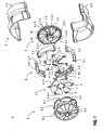
- the in FIG. 1 illustrated air vent 1, in particular for air conditioning of a vehicle interior, comprises a two-part substantially spherical housing 2.
- the housing 2 is formed of two half-shells 2.1 and 2.2.
- the housing 2 may be formed, for example, from a plastic molding or other suitable material.
- the housing 2 serves to receive a first air guide element 3 and a second air guide element 4 for setting different flow types.
- the first air-guiding element 3 is designed as a ring element 3.1, on which radially inwardly pointing blades 3.2.1 to 3.2.n of a rigid blade ring 3.2 are arranged whose blade ends are fastened on a ring element 3.1 centrally arranged hollow cylinder 3.3 for a spot-shaped air outflow.
- Under a rigid blade ring 3.2 are understood to be rigid and non-movable blades 3.2.1 to 3.2.n with a fixed setting to achieve a given flow.
- the blades 3.2.1 to 3.2.n can also be arranged adjustable or movable.
- the second air-guiding element 4 is formed from two further blade rings 4.1 and 4.2 arranged successively in the longitudinal extension of the air vent 1, with a plurality of blades 4.1.1 to 4.1.n or 4.2.1 to 4.2.n, which are movably held in ring segments 4.3 to 4.6.
- both the radially outwardly pointing blade ends of the blades 4.1.1 to 4.1.n and 4.2.1 to 4.2.n are movable in the housing segments 2 also movably arranged ring segments 4.3 to 4.6 and the radially inwardly facing blade ends of the blades 4.1 .1 to 4.1.n and 4.2.1 to 4.2.n movable or fixed on the hollow cylinder 3.3.
- the second air guide 4 may include only one movable blade ring 4.1 or more than two movable blade rings. Also, the second air guide element 4 may comprise a combination of movable and rigid blade rings in a further alternative embodiment.
- the blades 4.1.1 to 4.1.n and 4.2.1 to 4.2.n whose blade ends are provided at the end with pins 5 and 6, in the respective recesses 3.4 of the hollow cylinder 3.3 or at the other end in line guides 7 of the ring segments 4.3 to 4.6 are movably arranged.
- the number of lines 7 and the number of recesses 3.4 corresponds to the number of blades 4.1.1 to 4.1.n or 4.2.1 to 4.2.n of the respective blade ring 4.1 or 4.2.
- the line guides 7 are arranged distributed in circles K3 and K4 around the circumference of the ring segments 4.3 to 4.6.
- the distance between the recesses 3.4 and the line guides 7 The circles K1, K2 and K3, K4 is significantly determined by the distance of the blades 4.1.1 to 4.1.n or 4.2.1 to 4.2.n of the respective blade ring 4.1 or 4.2.
- the line guides 7 are preferably designed arcuate. However, the line guides 7 may also have another suitable curve shape.
- the blades 3.2.1 to 3.2.n and the blades 4.1.1 to 4.1.n and 4.2.1 to 4.2.n may be flat or curved.
- the blades 4.1.1 to 4.1.n and 4.2.1 to 4.2.n of the movable blade rings 4.1, 4.2 are preferably arranged to be flexible and twistable.
- the blades 3.2.1 to 3.2.n and 4.1.1 to 4.1.n and 4.2.1 to 4.2.n may have a suitable shape and e.g. be designed as a triangle or quadrilateral wing.
- an adjusting element 8 For adjusting both the flow direction, the flow as well as the amount of flow an adjusting element 8 is provided.
- the adjusting element 8 By means of the adjusting element 8 are the moving blades 4.1.1 to 4.1.n and 4.2.1 to 4.2 n of the movable blade rings 4.1 and 4.2 together and synchronously adjustable.
- other suitable means may be provided for, in particular, separate or separate adjustment of the blades 4.1.1 to 4.1.n and 4.2.1 to 4.2.n and / or the blade rings 4.1 and 4.2.
- the adjusting element 8 is on the flow output side to the interconnected in the assembled state ring segments 4.3 to 4.6 placed and locked to this.
- the adjusting element 8 comprises an adjusting ring 8.1, which is provided with recesses 8.2, which engage in the outer pins 6 of the blades 4.1.1 to 4.1.n and 4.2.1 to 4.2.n.
- the adjusting element 8 on the outlet side 8.1 on the adjusting 8.1 a margin 8.3, which is provided with a structure that allows a good gripping and adjusting the adjusting element 8.
- the adjustment element 8 can be provided with fixed or adjustable struts 8.4 on the flow output side. Instead of the struts 8.4 and slats can be provided.
- the adjusting element 8 is arranged lockable on the ring segments 4.3 to 4.6.
- the ring segments 4.3 to 4.6 on the outside a corresponding locking structure 4.7.
- Turning the adjusting ring 8.1 guides the blades guided in the line guides 7 4.1.1 to 4.1.n and 4.2.1 to 4.2.n, in whose pins 6 the recesses 8.2 of the adjusting element 8 engage, corresponding to the contour of the line guides 7, e.g. curved or curved, adjusted.
- the blades 4.1.1 to 4.1.n and 4.2.1 to 4.2.n are correspondingly twisted, wound or adjusted, so that a helical shape for a diffuse flow is adjustable.
- the outer air duct can be closed by appropriate position of the blades 4.1.1 to 4.1.n and 4.2.1 to 4.2.n.
- FIG. 1 shows an embodiment of the adjusting element 8 as adjusting ring 8.1 alternatively, the adjusting element 8 may be formed as a rotary knob and bevel gear.
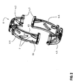
- FIG. 2 shows in detail the ring segments 4.3 to 4.6 of the second air guide element 4 according to FIG. 1 ,
- the arrangement of the line guides 7 distributed over the circumference in circles K3 and K4 is shown in detail.
- the lines 7 of the circle K3 take in the assembled state of the air vent 1, the pins 6 of the blades 4.1.1 to 4.1.n of the first movable blade ring 4.1 and the lines 7 of the circle K4 the pins 6 of the blades 4.2.1 to 4.2.n of second movable blade ring 4.2.
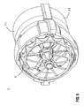
- FIG. 3 shows the two half-shells 2.1 and 2.2 of the housing 2.
- guide beads 9 are introduced.
- the spherical housing 2 forms a ball socket into which the ring segments 4.3 to 4.6 connected to one another in the mounted state are rotatably mounted in the manner of a ball and socket joint.
- the air vent 1 is therefore also referred to as a ball nozzle.
- a corresponding number of guide beads 9 are introduced on the inside into the housing 2, in particular in its half shells 2.1 to 2.2.
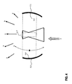
- a corresponding flow direction R or flow type - diffusive flow D or spot flow S - is set at the air vent 1 for the inlet flow E on the outlet side of the air vent 1 like this in FIG. 4 is shown.
- FIG. 5 shows an embodiment of an assembled air vent 1.
- the air vent may also have a plurality of identical or different first and second air guiding elements 3 and 4, which are designed to be movable or rigid and are arranged one behind the other along the longitudinal extent of the air vent 1.
Landscapes
- Physics & Mathematics (AREA)
- Thermal Sciences (AREA)
- Engineering & Computer Science (AREA)
- Mechanical Engineering (AREA)
- Air-Flow Control Members (AREA)
- Wind Motors (AREA)
- Devices For Medical Bathing And Washing (AREA)
- Air-Conditioning For Vehicles (AREA)
Applications Claiming Priority (2)
| Application Number | Priority Date | Filing Date | Title |
|---|---|---|---|
| DE102007010795A DE102007010795A1 (de) | 2007-03-02 | 2007-03-02 | Luftausströmer mit Drallströmung und konventioneller Strömung |
| PCT/EP2008/001223 WO2008107070A1 (de) | 2007-03-02 | 2008-02-18 | Luftausströmer mit drallströmung und konventioneller strömung |
Publications (2)
| Publication Number | Publication Date |
|---|---|
| EP2139709A1 EP2139709A1 (de) | 2010-01-06 |
| EP2139709B1 true EP2139709B1 (de) | 2010-07-14 |
Family
ID=39321517
Family Applications (1)
| Application Number | Title | Priority Date | Filing Date |
|---|---|---|---|
| EP08715823A Not-in-force EP2139709B1 (de) | 2007-03-02 | 2008-02-18 | Luftausströmer mit drallströmung und konventioneller strömung |
Country Status (5)
| Country | Link |
|---|---|
| EP (1) | EP2139709B1 (zh) |
| CN (1) | CN101622144B (zh) |
| AT (1) | ATE473877T1 (zh) |
| DE (2) | DE102007010795A1 (zh) |
| WO (1) | WO2008107070A1 (zh) |
Families Citing this family (25)
| Publication number | Priority date | Publication date | Assignee | Title |
|---|---|---|---|---|
| DE102008033339A1 (de) * | 2008-07-16 | 2010-01-21 | Behr Gmbh & Co. Kg | Luftausströmer mit Drallströmung und gerichteter Strömung |
| DE102009041532B4 (de) * | 2009-09-15 | 2011-11-24 | Trw Automotive Electronics & Components Gmbh | Dralleinrichtung für einen Luftausströmer |
| DE102009049116A1 (de) * | 2009-10-12 | 2011-04-14 | GM Global Technology Operations, Inc., Detroit | Lüfterdüse mit Stellring zum Verschwenken von Luftleitelementen |
| DE102009050885A1 (de) | 2009-10-27 | 2011-04-28 | Behr Gmbh & Co. Kg | Luftausströmer |
| DE102010001810A1 (de) | 2010-02-11 | 2011-08-11 | Behr GmbH & Co. KG, 70469 | Klimaanlage |
| DE102010014575B3 (de) * | 2010-04-12 | 2011-11-17 | Trw Automotive Electronics & Components Gmbh | Luftausströmer |
| DE102011108566B4 (de) | 2011-07-27 | 2014-01-09 | Audi Ag | Belüftungsdüse für den Innenraum eines Kraftfahrzeugs |
| CN103863060A (zh) * | 2012-12-11 | 2014-06-18 | 丹阳市飞越车辆附件有限公司 | 旋转式出风口组件 |
| JP6187654B2 (ja) * | 2013-02-21 | 2017-08-30 | 豊田合成株式会社 | ダンパ開閉装置 |
| US9933168B2 (en) * | 2013-05-31 | 2018-04-03 | Midea Group Co., Ltd. | Air supply apparatus used for air conditioner and air conditioner indoor unit having the same |
| CN103388895B (zh) * | 2013-06-25 | 2015-12-02 | 美的集团股份有限公司 | 空调器及空调器出风口开闭结构 |
| DE202014002057U1 (de) * | 2014-03-11 | 2015-06-12 | GM GLOBAL TECHNOLOGY OPERATION LLC (n. d. Ges. d. Staates Delaware) | Luftausströmer |
| DE102014205692A1 (de) | 2014-03-27 | 2015-10-01 | Mahle International Gmbh | Luftausströmer |
| DE102014208589A1 (de) | 2014-05-07 | 2015-11-12 | Mahle International Gmbh | Luftausströmer |
| US9707826B2 (en) * | 2014-07-31 | 2017-07-18 | GM Global Technology Operations LLC | Airflow outlet |
| KR101535039B1 (ko) * | 2014-09-24 | 2015-07-07 | 주식회사 니프코코리아 | 자동차의 에어벤트 |
| CN104729047B (zh) * | 2015-04-01 | 2017-08-22 | 宁波福尔达智能科技有限公司 | 汽车空调圆形出风口总成 |
| DE102015206609A1 (de) | 2015-04-14 | 2016-10-20 | Mahle International Gmbh | Luftstromsteuereinheit |
| DE102015206621A1 (de) | 2015-04-14 | 2016-10-20 | Mahle International Gmbh | Luftstromsteuereinheit |
| US9718329B2 (en) * | 2015-06-15 | 2017-08-01 | GM Global Technology Operations LLC | Airflow outlet assembly and a passenger compartment for a vehicle |
| CN107388391B (zh) * | 2017-08-31 | 2023-09-01 | 广东美的制冷设备有限公司 | 天花机 |
| CN109515120B (zh) * | 2018-12-21 | 2023-09-15 | 华晨鑫源重庆汽车有限公司 | 可发光汽车空调出风口结构 |
| CN109910560B (zh) * | 2019-03-13 | 2021-08-03 | 曼德电子电器有限公司 | 空调出风道气路控制机构 |
| CN109989941B (zh) * | 2019-04-25 | 2021-02-02 | 深圳创维空调科技有限公司 | 一种风机自调节导流圈及出风口导流控制方法 |
| CN111795381B (zh) * | 2020-07-23 | 2022-07-19 | 郑州轻工业大学 | 一种煤粉燃烧器用旋流叶片可调式旋流器 |
Family Cites Families (8)
| Publication number | Priority date | Publication date | Assignee | Title |
|---|---|---|---|---|
| FR2774633B1 (fr) | 1998-02-10 | 2000-05-05 | Regie Autonome Transports | Installation de ventilation forcee, notamment pour vehicule |
| FR2794690B1 (fr) * | 1999-06-10 | 2002-04-26 | Peugeot Citroen Automobiles Sa | Aerateur a ailettes |
| DE29914962U1 (de) | 1999-08-26 | 1999-10-14 | Bermes Peter | Luftauslaß, insbesondere für eine Kraftfahrzeug-Lüftung |
| DE10036776A1 (de) | 2000-07-28 | 2002-02-07 | Eberspaecher J Gmbh & Co | Einrichtung zur Klimatisierung eines Innenraumes mit Klimagerät und Luftheizgerät, insbesondere für ein Kraftfahrzeug |
| DE10232422A1 (de) * | 2002-07-17 | 2004-01-29 | Valeo Klimasysteme Gmbh | Luftklappenanordnung |
| GB2391932B (en) * | 2002-07-18 | 2004-06-30 | Pomin Wang | Automobile air-conditioning outlet deflection device |
| DE102005036159B4 (de) | 2005-01-10 | 2014-05-28 | Behr Gmbh & Co. Kg | Luftstromsteuereinheit |
| CN2813347Y (zh) * | 2005-07-19 | 2006-09-06 | 比亚迪股份有限公司 | 一种汽车空调出风口 |
-
2007
- 2007-03-02 DE DE102007010795A patent/DE102007010795A1/de not_active Withdrawn
-
2008
- 2008-02-18 WO PCT/EP2008/001223 patent/WO2008107070A1/de active Application Filing
- 2008-02-18 EP EP08715823A patent/EP2139709B1/de not_active Not-in-force
- 2008-02-18 DE DE502008000958T patent/DE502008000958D1/de active Active
- 2008-02-18 AT AT08715823T patent/ATE473877T1/de active
- 2008-02-18 CN CN2008800067432A patent/CN101622144B/zh not_active Expired - Fee Related
Also Published As
| Publication number | Publication date |
|---|---|
| EP2139709A1 (de) | 2010-01-06 |
| CN101622144A (zh) | 2010-01-06 |
| ATE473877T1 (de) | 2010-07-15 |
| DE502008000958D1 (de) | 2010-08-26 |
| DE102007010795A1 (de) | 2008-09-04 |
| CN101622144B (zh) | 2011-12-28 |
| WO2008107070A1 (de) | 2008-09-12 |
Similar Documents
| Publication | Publication Date | Title |
|---|---|---|
| EP2139709B1 (de) | Luftausströmer mit drallströmung und konventioneller strömung | |
| EP1923242B1 (de) | Luftausströmer mit Drallströmung und konventioneller Strömung | |
| EP1972476B1 (de) | Luftausströmer mit Drallströmung und gerichteter Strömung | |
| EP1800918B1 (de) | Luftausströmer mit Drallströmung | |
| EP2313285B1 (de) | Luftausströmer mit drallströmung und gerichteter strömung | |
| DE102007018022B4 (de) | Luftdüse | |
| DE102009041532B4 (de) | Dralleinrichtung für einen Luftausströmer | |
| DE19807292A1 (de) | Belüftungsvorrichtung für einen Innenraum | |
| WO2011029683A1 (de) | Bogenförmige luftdüse | |
| WO2019076577A1 (de) | Luftausströmer | |
| DE102006050999A1 (de) | Luftausströmer | |
| DE102017011497A1 (de) | Luftausströmer für eine Belüftungsanlage eines Fahrzeugs | |
| DE102006054847A1 (de) | Luftausströmer mit einem Einsatz aus verformbaren Material | |
| EP2117860B1 (de) | Luftausströmer, insbesondere für ein kraftfahrzeug | |
| DE102008005985B4 (de) | Luftausströmer | |
| DE60205335T2 (de) | Lüftungsgitter, insbesondere für Kraftfahrzeuge | |
| DE102015206621A1 (de) | Luftstromsteuereinheit | |
| DE102012204555A1 (de) | Luftausströmer | |
| DE102011075977A1 (de) | Komfortdüse | |
| EP1782977B1 (de) | Luftausströmer | |
| DE102012013506B4 (de) | Luftstrom-Verstellvorrichtung für einen Luftausströmer eines Fahrzeugs und Luftausströmer für ein Fahrzeug | |
| DE102021130825A1 (de) | Luftausströmer für eine Fahrgastzelle eines Kraftwagens | |
| DE102015206609A1 (de) | Luftstromsteuereinheit | |
| DE102021210595A1 (de) | Radiallüfter mit mindestens einem luftaustrittsseitig angeordneten Luftleitelement und Fahrzeugsitz mit einem solchen Radiallüfter | |
| DE102019102287A1 (de) | Luftstromsteuerungsvorrichtung zur Verteilung eines Luftstroms auf eine Mehrzahl Auslasskanäle |
Legal Events
| Date | Code | Title | Description |
|---|---|---|---|
| PUAI | Public reference made under article 153(3) epc to a published international application that has entered the european phase |
Free format text: ORIGINAL CODE: 0009012 |
|
| 17P | Request for examination filed |
Effective date: 20091002 |
|
| AK | Designated contracting states |
Kind code of ref document: A1 Designated state(s): AT BE BG CH CY CZ DE DK EE ES FI FR GB GR HR HU IE IS IT LI LT LU LV MC MT NL NO PL PT RO SE SI SK TR |
|
| GRAP | Despatch of communication of intention to grant a patent |
Free format text: ORIGINAL CODE: EPIDOSNIGR1 |
|
| DAX | Request for extension of the european patent (deleted) | ||
| GRAS | Grant fee paid |
Free format text: ORIGINAL CODE: EPIDOSNIGR3 |
|
| GRAA | (expected) grant |
Free format text: ORIGINAL CODE: 0009210 |
|
| AK | Designated contracting states |
Kind code of ref document: B1 Designated state(s): AT BE BG CH CY CZ DE DK EE ES FI FR GB GR HR HU IE IS IT LI LT LU LV MC MT NL NO PL PT RO SE SI SK TR |
|
| REG | Reference to a national code |
Ref country code: GB Ref legal event code: FG4D Free format text: NOT ENGLISH |
|
| REG | Reference to a national code |
Ref country code: CH Ref legal event code: EP |
|
| REG | Reference to a national code |
Ref country code: IE Ref legal event code: FG4D |
|
| REF | Corresponds to: |
Ref document number: 502008000958 Country of ref document: DE Date of ref document: 20100826 Kind code of ref document: P |
|
| REG | Reference to a national code |
Ref country code: SE Ref legal event code: TRGR |
|
| REG | Reference to a national code |
Ref country code: NL Ref legal event code: VDEP Effective date: 20100714 |
|
| LTIE | Lt: invalidation of european patent or patent extension |
Effective date: 20100714 |
|
| PG25 | Lapsed in a contracting state [announced via postgrant information from national office to epo] |
Ref country code: FI Free format text: LAPSE BECAUSE OF FAILURE TO SUBMIT A TRANSLATION OF THE DESCRIPTION OR TO PAY THE FEE WITHIN THE PRESCRIBED TIME-LIMIT Effective date: 20100714 Ref country code: NL Free format text: LAPSE BECAUSE OF FAILURE TO SUBMIT A TRANSLATION OF THE DESCRIPTION OR TO PAY THE FEE WITHIN THE PRESCRIBED TIME-LIMIT Effective date: 20100714 Ref country code: NO Free format text: LAPSE BECAUSE OF FAILURE TO SUBMIT A TRANSLATION OF THE DESCRIPTION OR TO PAY THE FEE WITHIN THE PRESCRIBED TIME-LIMIT Effective date: 20101014 Ref country code: LT Free format text: LAPSE BECAUSE OF FAILURE TO SUBMIT A TRANSLATION OF THE DESCRIPTION OR TO PAY THE FEE WITHIN THE PRESCRIBED TIME-LIMIT Effective date: 20100714 |
|
| REG | Reference to a national code |
Ref country code: IE Ref legal event code: FD4D |
|
| PG25 | Lapsed in a contracting state [announced via postgrant information from national office to epo] |
Ref country code: IS Free format text: LAPSE BECAUSE OF FAILURE TO SUBMIT A TRANSLATION OF THE DESCRIPTION OR TO PAY THE FEE WITHIN THE PRESCRIBED TIME-LIMIT Effective date: 20101114 Ref country code: PL Free format text: LAPSE BECAUSE OF FAILURE TO SUBMIT A TRANSLATION OF THE DESCRIPTION OR TO PAY THE FEE WITHIN THE PRESCRIBED TIME-LIMIT Effective date: 20100714 Ref country code: SI Free format text: LAPSE BECAUSE OF FAILURE TO SUBMIT A TRANSLATION OF THE DESCRIPTION OR TO PAY THE FEE WITHIN THE PRESCRIBED TIME-LIMIT Effective date: 20100714 Ref country code: HR Free format text: LAPSE BECAUSE OF FAILURE TO SUBMIT A TRANSLATION OF THE DESCRIPTION OR TO PAY THE FEE WITHIN THE PRESCRIBED TIME-LIMIT Effective date: 20100714 Ref country code: BG Free format text: LAPSE BECAUSE OF FAILURE TO SUBMIT A TRANSLATION OF THE DESCRIPTION OR TO PAY THE FEE WITHIN THE PRESCRIBED TIME-LIMIT Effective date: 20101014 Ref country code: CY Free format text: LAPSE BECAUSE OF FAILURE TO SUBMIT A TRANSLATION OF THE DESCRIPTION OR TO PAY THE FEE WITHIN THE PRESCRIBED TIME-LIMIT Effective date: 20100714 |
|
| PG25 | Lapsed in a contracting state [announced via postgrant information from national office to epo] |
Ref country code: LV Free format text: LAPSE BECAUSE OF FAILURE TO SUBMIT A TRANSLATION OF THE DESCRIPTION OR TO PAY THE FEE WITHIN THE PRESCRIBED TIME-LIMIT Effective date: 20100714 Ref country code: GR Free format text: LAPSE BECAUSE OF FAILURE TO SUBMIT A TRANSLATION OF THE DESCRIPTION OR TO PAY THE FEE WITHIN THE PRESCRIBED TIME-LIMIT Effective date: 20101015 |
|
| PG25 | Lapsed in a contracting state [announced via postgrant information from national office to epo] |
Ref country code: IE Free format text: LAPSE BECAUSE OF FAILURE TO SUBMIT A TRANSLATION OF THE DESCRIPTION OR TO PAY THE FEE WITHIN THE PRESCRIBED TIME-LIMIT Effective date: 20100714 Ref country code: DK Free format text: LAPSE BECAUSE OF FAILURE TO SUBMIT A TRANSLATION OF THE DESCRIPTION OR TO PAY THE FEE WITHIN THE PRESCRIBED TIME-LIMIT Effective date: 20100714 |
|
| PLBE | No opposition filed within time limit |
Free format text: ORIGINAL CODE: 0009261 |
|
| STAA | Information on the status of an ep patent application or granted ep patent |
Free format text: STATUS: NO OPPOSITION FILED WITHIN TIME LIMIT |
|
| PG25 | Lapsed in a contracting state [announced via postgrant information from national office to epo] |
Ref country code: RO Free format text: LAPSE BECAUSE OF FAILURE TO SUBMIT A TRANSLATION OF THE DESCRIPTION OR TO PAY THE FEE WITHIN THE PRESCRIBED TIME-LIMIT Effective date: 20100714 Ref country code: CZ Free format text: LAPSE BECAUSE OF FAILURE TO SUBMIT A TRANSLATION OF THE DESCRIPTION OR TO PAY THE FEE WITHIN THE PRESCRIBED TIME-LIMIT Effective date: 20100714 Ref country code: SK Free format text: LAPSE BECAUSE OF FAILURE TO SUBMIT A TRANSLATION OF THE DESCRIPTION OR TO PAY THE FEE WITHIN THE PRESCRIBED TIME-LIMIT Effective date: 20100714 Ref country code: EE Free format text: LAPSE BECAUSE OF FAILURE TO SUBMIT A TRANSLATION OF THE DESCRIPTION OR TO PAY THE FEE WITHIN THE PRESCRIBED TIME-LIMIT Effective date: 20100714 |
|
| 26N | No opposition filed |
Effective date: 20110415 |
|
| PG25 | Lapsed in a contracting state [announced via postgrant information from national office to epo] |
Ref country code: ES Free format text: LAPSE BECAUSE OF FAILURE TO SUBMIT A TRANSLATION OF THE DESCRIPTION OR TO PAY THE FEE WITHIN THE PRESCRIBED TIME-LIMIT Effective date: 20101025 |
|
| REG | Reference to a national code |
Ref country code: DE Ref legal event code: R097 Ref document number: 502008000958 Country of ref document: DE Effective date: 20110415 |
|
| BERE | Be: lapsed |
Owner name: BEHR G.M.B.H. & CO. KG Effective date: 20110228 |
|
| PG25 | Lapsed in a contracting state [announced via postgrant information from national office to epo] |
Ref country code: MC Free format text: LAPSE BECAUSE OF NON-PAYMENT OF DUE FEES Effective date: 20110228 |
|
| PG25 | Lapsed in a contracting state [announced via postgrant information from national office to epo] |
Ref country code: BE Free format text: LAPSE BECAUSE OF NON-PAYMENT OF DUE FEES Effective date: 20110228 |
|
| PG25 | Lapsed in a contracting state [announced via postgrant information from national office to epo] |
Ref country code: MT Free format text: LAPSE BECAUSE OF FAILURE TO SUBMIT A TRANSLATION OF THE DESCRIPTION OR TO PAY THE FEE WITHIN THE PRESCRIBED TIME-LIMIT Effective date: 20100714 |
|
| PGFP | Annual fee paid to national office [announced via postgrant information from national office to epo] |
Ref country code: IT Payment date: 20120321 Year of fee payment: 5 Ref country code: SE Payment date: 20120315 Year of fee payment: 5 |
|
| REG | Reference to a national code |
Ref country code: CH Ref legal event code: PL |
|
| PG25 | Lapsed in a contracting state [announced via postgrant information from national office to epo] |
Ref country code: LI Free format text: LAPSE BECAUSE OF NON-PAYMENT OF DUE FEES Effective date: 20120229 Ref country code: CH Free format text: LAPSE BECAUSE OF NON-PAYMENT OF DUE FEES Effective date: 20120229 |
|
| PG25 | Lapsed in a contracting state [announced via postgrant information from national office to epo] |
Ref country code: LU Free format text: LAPSE BECAUSE OF NON-PAYMENT OF DUE FEES Effective date: 20110218 |
|
| PG25 | Lapsed in a contracting state [announced via postgrant information from national office to epo] |
Ref country code: PT Free format text: LAPSE BECAUSE OF NON-PAYMENT OF DUE FEES Effective date: 20100714 |
|
| PG25 | Lapsed in a contracting state [announced via postgrant information from national office to epo] |
Ref country code: TR Free format text: LAPSE BECAUSE OF FAILURE TO SUBMIT A TRANSLATION OF THE DESCRIPTION OR TO PAY THE FEE WITHIN THE PRESCRIBED TIME-LIMIT Effective date: 20100714 |
|
| REG | Reference to a national code |
Ref country code: SE Ref legal event code: EUG |
|
| PG25 | Lapsed in a contracting state [announced via postgrant information from national office to epo] |
Ref country code: HU Free format text: LAPSE BECAUSE OF FAILURE TO SUBMIT A TRANSLATION OF THE DESCRIPTION OR TO PAY THE FEE WITHIN THE PRESCRIBED TIME-LIMIT Effective date: 20100714 Ref country code: SE Free format text: LAPSE BECAUSE OF NON-PAYMENT OF DUE FEES Effective date: 20130219 |
|
| PG25 | Lapsed in a contracting state [announced via postgrant information from national office to epo] |
Ref country code: IT Free format text: LAPSE BECAUSE OF NON-PAYMENT OF DUE FEES Effective date: 20130218 |
|
| REG | Reference to a national code |
Ref country code: AT Ref legal event code: MM01 Ref document number: 473877 Country of ref document: AT Kind code of ref document: T Effective date: 20130218 |
|
| PG25 | Lapsed in a contracting state [announced via postgrant information from national office to epo] |
Ref country code: AT Free format text: LAPSE BECAUSE OF NON-PAYMENT OF DUE FEES Effective date: 20130218 |
|
| REG | Reference to a national code |
Ref country code: DE Ref legal event code: R082 Ref document number: 502008000958 Country of ref document: DE Representative=s name: GRAUEL, ANDREAS, DIPL.-PHYS. DR. RER. NAT., DE |
|
| REG | Reference to a national code |
Ref country code: DE Ref legal event code: R082 Ref document number: 502008000958 Country of ref document: DE Representative=s name: GRAUEL, ANDREAS, DIPL.-PHYS. DR. RER. NAT., DE Effective date: 20150227 Ref country code: DE Ref legal event code: R081 Ref document number: 502008000958 Country of ref document: DE Owner name: MAHLE INTERNATIONAL GMBH, DE Free format text: FORMER OWNER: BEHR GMBH & CO. KG, 70469 STUTTGART, DE Effective date: 20150227 |
|
| REG | Reference to a national code |
Ref country code: FR Ref legal event code: PLFP Year of fee payment: 9 |
|
| REG | Reference to a national code |
Ref country code: FR Ref legal event code: PLFP Year of fee payment: 10 |
|
| REG | Reference to a national code |
Ref country code: FR Ref legal event code: PLFP Year of fee payment: 11 |
|
| PGFP | Annual fee paid to national office [announced via postgrant information from national office to epo] |
Ref country code: DE Payment date: 20190304 Year of fee payment: 12 Ref country code: GB Payment date: 20190225 Year of fee payment: 12 |
|
| PGFP | Annual fee paid to national office [announced via postgrant information from national office to epo] |
Ref country code: FR Payment date: 20190224 Year of fee payment: 12 |
|
| REG | Reference to a national code |
Ref country code: DE Ref legal event code: R119 Ref document number: 502008000958 Country of ref document: DE |
|
| GBPC | Gb: european patent ceased through non-payment of renewal fee |
Effective date: 20200218 |
|
| PG25 | Lapsed in a contracting state [announced via postgrant information from national office to epo] |
Ref country code: GB Free format text: LAPSE BECAUSE OF NON-PAYMENT OF DUE FEES Effective date: 20200218 Ref country code: DE Free format text: LAPSE BECAUSE OF NON-PAYMENT OF DUE FEES Effective date: 20200901 |
|
| PG25 | Lapsed in a contracting state [announced via postgrant information from national office to epo] |
Ref country code: FR Free format text: LAPSE BECAUSE OF NON-PAYMENT OF DUE FEES Effective date: 20200302 |