EP2137464B1 - Radiateurs - Google Patents
Radiateurs Download PDFInfo
- Publication number
- EP2137464B1 EP2137464B1 EP08719082.3A EP08719082A EP2137464B1 EP 2137464 B1 EP2137464 B1 EP 2137464B1 EP 08719082 A EP08719082 A EP 08719082A EP 2137464 B1 EP2137464 B1 EP 2137464B1
- Authority
- EP
- European Patent Office
- Prior art keywords
- radiator
- radiators
- gas controller
- flow path
- control unit
- Prior art date
- Legal status (The legal status is an assumption and is not a legal conclusion. Google has not performed a legal analysis and makes no representation as to the accuracy of the status listed.)
- Active
Links
- 238000000034 method Methods 0.000 claims description 30
- 239000012530 fluid Substances 0.000 claims description 23
- 238000011144 upstream manufacturing Methods 0.000 claims description 2
- 230000005611 electricity Effects 0.000 description 35
- 238000004891 communication Methods 0.000 description 27
- 238000012544 monitoring process Methods 0.000 description 19
- XLYOFNOQVPJJNP-UHFFFAOYSA-N water Substances O XLYOFNOQVPJJNP-UHFFFAOYSA-N 0.000 description 15
- 238000010438 heat treatment Methods 0.000 description 11
- 230000000694 effects Effects 0.000 description 3
- XEEYBQQBJWHFJM-UHFFFAOYSA-N Iron Chemical compound [Fe] XEEYBQQBJWHFJM-UHFFFAOYSA-N 0.000 description 2
- 230000002528 anti-freeze Effects 0.000 description 2
- 230000007423 decrease Effects 0.000 description 2
- 230000003247 decreasing effect Effects 0.000 description 2
- 239000003112 inhibitor Substances 0.000 description 2
- JEIPFZHSYJVQDO-UHFFFAOYSA-N iron(III) oxide Inorganic materials O=[Fe]O[Fe]=O JEIPFZHSYJVQDO-UHFFFAOYSA-N 0.000 description 2
- 230000003213 activating effect Effects 0.000 description 1
- 238000013475 authorization Methods 0.000 description 1
- 239000003795 chemical substances by application Substances 0.000 description 1
- 238000004140 cleaning Methods 0.000 description 1
- 230000001419 dependent effect Effects 0.000 description 1
- 238000007689 inspection Methods 0.000 description 1
- 235000000396 iron Nutrition 0.000 description 1
- 229910052742 iron Inorganic materials 0.000 description 1
- 238000012986 modification Methods 0.000 description 1
- 230000004048 modification Effects 0.000 description 1
- 238000005086 pumping Methods 0.000 description 1
Images


Classifications
-
- F—MECHANICAL ENGINEERING; LIGHTING; HEATING; WEAPONS; BLASTING
- F24—HEATING; RANGES; VENTILATING
- F24H—FLUID HEATERS, e.g. WATER OR AIR HEATERS, HAVING HEAT-GENERATING MEANS, e.g. HEAT PUMPS, IN GENERAL
- F24H3/00—Air heaters
- F24H3/002—Air heaters using electric energy supply
- F24H3/004—Air heaters using electric energy supply with a closed circuit for a heat transfer liquid
-
- F—MECHANICAL ENGINEERING; LIGHTING; HEATING; WEAPONS; BLASTING
- F24—HEATING; RANGES; VENTILATING
- F24D—DOMESTIC- OR SPACE-HEATING SYSTEMS, e.g. CENTRAL HEATING SYSTEMS; DOMESTIC HOT-WATER SUPPLY SYSTEMS; ELEMENTS OR COMPONENTS THEREFOR
- F24D19/00—Details
- F24D19/10—Arrangement or mounting of control or safety devices
- F24D19/1096—Arrangement or mounting of control or safety devices for electric heating systems
Definitions
- the present invention relates to radiators, methods of operating radiators, a radiator system and a method of operating a radiator system, methods of controlling the electricity consumed in a unit including at least one radiator and radiator electricity consumption systems.
- Patents that relate to general heating systems are GB 2206685 , GB 2411462 , GB 2305720 , GB 2251063 , GB 2298265 , GB 2211593 , WO 2005/045326 , WO 2004/102077 , WO 03/042607 , WO 2005/022953 , EP 1653165 and EP 088681 .
- a radiator comprising a sealed flow path through which, in use, electrically heated fluid is arranged to pass, a control unit arranged to control operation of the radiator and a receiving unit arranged to receive at least one operation instruction from a remote control unit in use, and which is arranged to pass the at least one operation instruction to the control unit so that, in use, the radiator is controllable by the remote control unit the flow path including a gas controller (20) comprising up and down stream parts of the path and an intermediate portion between those up and down stream parts, the intermediate portion being at a greater elevation than the up and down stream parts.
- the at least one operation instruction comprises a temperature setting.
- the at least one operation instruction comprises operation start and stop times for the radiator.
- the present invention also includes a method of operating a radiator when the radiator is as herein referred to and vice versa.
- Monitoring means may be provided arranged, in use, to monitor the rate of electricity consumption of the radiator and to control the flow of electricity to the radiator in dependence upon the monitored consumption.
- a method of controlling the electricity consumed in a unit may include at least one radiator comprising a sealed flow path through which electrically heated fluid is arranged to pass comprises monitoring the electricity being consumed by the or each radiator in the unit and controlling the rate of consumption of electricity by the o r ea c h radiator in dependence upon the monitored consumption.
- the radiator may be arranged, in use, to control the amount of electricity that the or each radiator is able to consume over a period of time.
- the radiator may include means for communicating with another radiator or a central control so that, in use, the other radiator or central control can determine that the radiator is unavailable.
- the radiator may include a flow path including a gas controller comprising up and downstream parts of the path and an intermediate portion between these up and downstream parts, the intermediate portion being at a greater elevation than the up and downstream parts.
- the radiator may include first communication means arranged to co-operate with second communication means.
- the radiator may include monitoring means arranged, in use, to monitor the rate of electricity consumption of the radiator and to control the flow of electricity to the radiator in dependence upon the monitored consumption.
- the radiator may include restriction means arranged, in use, to restrict the amount of electricity that the or each radiator is able to consume over a period of time.
- the radiator may be located in a zone and may include means for monitoring the entry of a person into the zone and means to cause heat to be added to the zone, if required, after the entry of a person into the zone has been monitored.
- a radiator comprises a heater and a sealed flow path through which, in use, heated fluid is arranged to pass, the flow path including a ga s controller comprising up and downstream parts with the path and an intermediate portion between these up and downstream parts, the intermediate portion being at a greater elevation and the up and downstream parts.
- a method of operating a radiator including a sealed flow path comprising heating fluid and causing the heated fluid to pass through a gas controller by flow first through an upstream part, then through a intermediate portion and then through a downstream part with the intermediate portion being at a greater elevation than the up and downstream parts with gas being controlled in the intermediate portion and with fluid passing through the intermediate portion.
- a radiator system may include at least one radiator comprising a sealed flow path through which, in use, heated fluid is arranged to pass, the radiator including first communication means, the system further including separate second communication means arrange to co-operate with the first communication means.
- the present invention also includes a method of operating a radiator system when the radiator is as herein referred to.
- the radiator may include monitoring means arranged, in use, to monitor the rate of electricity consumption of the radiator and to control the flow of electricity to the radiator in dependence upon the monitored consumption.
- the radiator may include restriction means arranged, in use, to restrict the amount of electricity that the or each radiator is able to consume over a period of time.
- the radiator may be located in a zone and may include means for monitoring the entry of a person into the zone and means to cause heat to be added to the zone, if required, after the entry of a person into the zone has been monitored.
- the second communication means may be provided by a second radiator spaced from the first radiator, the second radiator also including a sealed flow path through which, in use, heated fluid is arranged to pass. There may be three or more such radiators each including communication means.
- At least one radiator may be able to communicate with another radiator.
- Each radiator may be arranged, in use, to communicate with all of the other radiators. Alternatively only some of the radiators may be able to communicate with all of the other radiators. Alternatively none of the radiators may be able to communicate with all of the other radiators. Alternatively each radiator may be able to communicate with some but not all radiators. Alternatively each radiator may be able to communicate with only one other radiator with no radiator being unable to communicate with another.
- Radiators may be able to communicate in series with each other. Radiators may be able to control the amount of electricity consumed by at least one other radiator.
- At least one or all radiators may be able to communicate with second communication means that are not on a radiator.
- the alarm may be remote from the radiators and, alternatively or additionally, remote from all of the communicate means.
- At least one radiator may include authorisation means which authorise the radiator to be able to operate when the communication means cooperate with another. When a communication between two communication means is unable to be made, at least one radiator may be prevented from operating.
- a method of controlling the electricity consumed in a unit may include at least one radiator comprising a sealed flow path through which electrically heated fluid passes, comprising controlling the amount of electricity that at least one radiator is able to consume over a period of time.
- a radiator electricity consumption system in a unit including at least one radiator comprising a sealed flow path through which, in use, electrically heated fluid is arranged to pass and restriction means arranged, in use, to restrict the amount of electricity that the or each radiator is able to consume over a period of time.
- the radiator may include first communication means arranged to co-operate with separate second communication means.
- the radiator may include monitoring means arranged, in use, to monitor the rate of electricity consumption of the radiator and to control the flow of electricity to the radiator in dependence upon the monitored consumption.
- the radiator may be located in a zone and may include means for monitoring the entry of a person into the zone and means to cause heat to be added to the zone, if required, after the entry of a person into the zone has been monitored.
- the method may comprise varying the amount of electricity that is able to be consumed over a specific period for instance by a person paying more or less for the electricity over a period.
- the method may comprise permitting at least one radiator to always be able to consume electricity for at least part or parts of the period.
- the method may comprise restricting the amount of electricity that is able to be consumed by a plurality of radiators and prioritising the consumption of at least one radiator over another.
- the method may comprise effecting the restriction to limit the rate of consumption of at least one radiator either for part of parts of the time in any one period or for all of that period.
- the method may comprise preventing at least one radiator from consuming power for at least part of the period.
- the restriction may be effected by an authorised person.
- the restriction may be effected by control means which may effect the restriction based on an amount paid.
- an electricity consumption system is arranged, in use, to control the electricity consumed in a unit that includes at least one radiator comprising a sealed flow path through which, in use, electrically heated fluid is arranged to pass, the system including monitoring means arranged, in use, to monitor the electricity consumption of the or each radiator in a unit and control means arranged, in use, to control the flow of electricity to the or each radiator in dependence upon the consumption monitored by the monitoring means.
- the radiator may include first communication means arranged to co-operate with separate second communication means.
- the radiator may include restriction means arranged, in use, to restrict the amount of electricity that a radiator is able to consume over a period of time.
- the radiator may be located in a zone and may include means for monitoring the entry of a person into the zone and means to cause heat to be added to the zone, if required, after the entry of a person into the zone has been monitored.
- the method may comprise controlling the rate of consumption such that the rate of consumption by two or more radiators is always less than the maximum rate that could be consumed by all radiators if each were operating at their maximum rate.
- the method may comprise controlling the rate of consumption of two or more radiators by allowing at least one radiator to consume more than at least one other radiator.
- the method may comprise the control first allowing a first radiator to be able to consume electricity at a greater rate than a second radiator and then allowing the second radiator to be able to consume at a greater rate than the first.
- the method may comprise monitoring the rate of electrical consumption by the or each radiator and also the rate of consumption of at least one other item in the unit and controlling the rate of consumption of the radiator in dependence upon that monitoring.
- the method may comprise monitoring the rate of electrical consumption of the complete unit.
- the unit may comprise a house.
- a method of operating a radiator in a zone may comprise monitoring the entry of a person into a zone causing a radiator to add heat to the zone, if required, after the initial monitoring of the entry.
- the method may comprise adding heat after a predetermined period of time has passed since the person entered the room provided the person is still monitored as being in the room.
- the method may comprise adding heat if the activity of the person falls below a certain rate after they have been monitored as having entered the room.
- the addition of heat may enable the radiator to supply heat if the temperature in the room is below a predetermined temperature.
- the radiator may include first communication means arranged to co-operate with second communication means.
- the radiator may include monitoring means arranged, in use, to monitor the rate of electricity consumption of the radiator and to control the flow of electricity to the radiator in dependence upon the monitored consumption.
- the radiator may include restriction means arranged, in use, to restrict the amount of electricity that the or each radiator is able to consume over a period of time.
- a zone heating system may include a radiator and a monitor arranged to monitor the entry of a person into the room and control means arranged to turn the radiator on after the entry of the person into the zone has been monitored.
- a triac may be in thermal communication with a heater used to electrically heat the fluid, so that the triac is cooled by the heater.
- the fluid driving means comprises a pump and the controller is arranged to intermittently start the pump when operation of the radiator is initiated.
- the controller is arranged to send a pulsed start signal to the pump.
- a duty cycle of the pulsed start signal is gradually increased.
- the radiator comprises a separable cover arranged to surround the radiator when mounted on a wall.
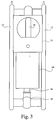
- the water then passes through a pipe that extends first upwardly then downwardly to form a loop or inverted U-bend 20.
- the pipe may have a cross-sectional area of more than 5 mm 2 or 7 mm 2 or 9 mm 2 or 12 mm 2 .
- the cross section may be less than 70 or 50 or 30 mm 2 and is preferably in the region of 20 mm 2 .
- the pipe may have a circular cross-section.
- the water then flows along a horizontal pipe 22 before passing into a knuckle joint 24.
- the water then flows through the heater panels 12 at each side and upwardly through those panels to knuckle joints 26 and 28 at the top region of the radiator before exiting the radiator panels 12 through a lower knuckle joint 30 that feeds the inlet pipe 16 for the heater.
- the radiator is set up in factory conditions. Water with antifreeze content and rust inhibitor is added through an inlet valve (not shown) in one of the knuckle joints with the air leaving through an outlet valve (not shown) in another such joint.
- the water flows through the complete radiator system to remove substantially all of the air in the system.
- the water is also heated and the internal pressure is set at 0 or 4 bar for instance or at any desired pressure. The pressure may vary during use. Then the inlet and outlet valves are closed and the system is transported to the area where it is to be used.
- the radiator In use the radiator is plugged into the electric mains to provide the power for the radiator and for a control unit 32 that is mounted on and sealed to the top of the heater 14. As the control unit is sealed on top of the boiler, and as there are no switches or other contacts that are exposed to the atmosphere, the radiator is able to be used in a bathroom.
- radiators for instance, from 1, to a plurality of radiators to, for instance, 7 are distributed around a house with perhaps two radiators being in one room and a single radiator being in another room.
- the radiators are not connected together and each has its own pump, boiler and internal water circulation.
- Each radiator is plugged into the same electric mains system.
- the radiators that are sold each include the same control unit even though all of the controls that will be described later in a unit may not necessarily be utilised for any particular radiator.
- the radiators can be sold with all items being of the same size but with, for instance, the heater having a one or two or three KW coiled heating element.
- Various modes of operation will now be described. The modes are not mutually exclusive and could be used together, at the same time, where feasible, or at different times.
Claims (15)
- Radiateur (10) comprenant un élément chauffant électrique (14) et une voie d'écoulement étanche dans laquelle, lors de l'utilisation, un fluide chauffé électriquement est mis en circulation par moyen de circulation de fluide (18), une unité de régulation conçue pour réguler le fonctionnement du radiateur (10), le radiateur étant caractérisé en ce qu'il comprend en outre une unité de réception conçue pour recevoir, lors de l'utilisation, au moins une instruction de fonctionnement provenant d'une unité de régulation distante, et conçue pour transmettre l'au moins une instruction de fonctionnement à l'unité de régulation de sorte que, lors de l'utilisation, le radiateur (10) puisse être régulé par l'unité de régulation distante, la voie d'écoulement comprenant un contrôleur de gaz (20) comprenant des parties en amont et en aval de la voie, et une partie intermédiaire entre ces parties en amont et en aval, la partie intermédiaire étant à une hauteur supérieure à celle des parties en amont et en aval.
- Radiateur (10) selon la revendication 1, dans lequel le contrôleur de gaz (20) comprend une section transversale supérieure à 5 mm2.
- Radiateur (10) selon la revendication 1 ou 2, dans lequel le contrôleur de gaz (20) comprend une section transversale inférieure à 70 mm2.
- Radiateur (10) selon l'une quelconque des revendications précédentes, dans lequel la partie inférieure de la partie intermédiaire est à une hauteur supérieure à celle des parties en amont et en aval.
- Radiateur (10) selon l'une quelconque des revendications précédentes, dans lequel le contrôleur de gaz (20) comprend un U inversé.
- Radiateur (10) selon l'une quelconque des revendications précédentes, dans lequel les parties en amont et/ou en aval comprennent un canal s'étendant verticalement le long d'au moins une partie de leur extension.
- Radiateur (10) selon l'une quelconque des revendications précédentes, le radiateur (10) comprenant au moins une partie rayonnante (12), et le contrôleur de gaz (20) étant situé à proximité de cette partie rayonnante (12).
- Radiateur (10) selon la revendication 7, dans lequel le contrôleur de gaz (20) est situé d'un côté de la partie rayonnante (12).
- Radiateur (10) selon la revendication 8, comprenant deux parties rayonnantes (12), et le contrôleur de gaz (20) étant situé entre ces deux parties rayonnantes (12).
- Radiateur (10) selon l'une quelconque des revendications 7 à 9, dans lequel la voie d'écoulement étanche comprend un fluide s'écoulant dans au moins une partie rayonnante (12).
- Radiateur (10) selon la revendication 10, dans lequel le fluide quittant la partie en aval est fourni à au moins une partie rayonnante (12).
- Radiateur (10) selon l'une quelconque des revendications 8 à 11, dans lequel le contrôleur de gaz (20) est à une hauteur inférieure à celle de l'extension supérieure de la voie d'écoulement dans au moins une partie rayonnante (12).
- Radiateur (10) selon l'une quelconque des revendications précédentes, dans lequel le contrôleur de gaz (20) est en aval du moyen de circulation de fluide (18).
- Radiateur (10) selon l'une quelconque des revendications 7 à 19, dans lequel le contrôleur de gaz (20) est en aval de l'élément chauffant (14).
- Procédé de régulation d'un radiateur (10) comprenant une voie d'écoulement étanche dans laquelle un fluide chauffé électriquement est mis en circulation, le procédé étant caractérisé en ce qu'il comprend les étapes consistant à envoyer au radiateur (10) au moins une instruction de fonctionnement provenant d'une unité de régulation distante, recevoir l'au moins une instruction de fonctionnement au niveau du radiateur (10), réguler le fonctionnement du radiateur (10) en fonction de l'au moins une instruction de fonctionnement, et amener le fluide chauffé à passer dans un contrôleur de gaz (20) en s'écoulant d'abord dans une partie en amont, puis dans une partie intermédiaire, puis dans une partie en aval, la partie intermédiaire étant à une hauteur supérieure à celle des parties en amont et en aval.
Applications Claiming Priority (2)
| Application Number | Priority Date | Filing Date | Title |
|---|---|---|---|
| GBGB0707147.5A GB0707147D0 (en) | 2007-04-13 | 2007-04-13 | Radiators |
| PCT/GB2008/050237 WO2008125875A2 (fr) | 2007-04-13 | 2008-04-02 | Radiateurs |
Publications (2)
| Publication Number | Publication Date |
|---|---|
| EP2137464A2 EP2137464A2 (fr) | 2009-12-30 |
| EP2137464B1 true EP2137464B1 (fr) | 2016-10-26 |
Family
ID=38116676
Family Applications (1)
| Application Number | Title | Priority Date | Filing Date |
|---|---|---|---|
| EP08719082.3A Active EP2137464B1 (fr) | 2007-04-13 | 2008-04-02 | Radiateurs |
Country Status (9)
| Country | Link |
|---|---|
| US (1) | US9022299B2 (fr) |
| EP (1) | EP2137464B1 (fr) |
| AU (1) | AU2008237680A1 (fr) |
| CA (1) | CA2683853C (fr) |
| ES (1) | ES2610605T3 (fr) |
| GB (1) | GB0707147D0 (fr) |
| NZ (1) | NZ580292A (fr) |
| PL (1) | PL2137464T3 (fr) |
| WO (1) | WO2008125875A2 (fr) |
Families Citing this family (7)
| Publication number | Priority date | Publication date | Assignee | Title |
|---|---|---|---|---|
| EP2938933B1 (fr) * | 2012-12-31 | 2018-09-12 | Steelmax Tech SA | Radiateur autonome stimulé électriquement |
| GB201315141D0 (en) * | 2013-08-23 | 2013-10-09 | Logicor R & D Ltd | Improvements to electric heating systems and method of use thereof |
| EP2960594A1 (fr) * | 2014-06-24 | 2015-12-30 | Bleckmann GmbH & Co. KG | Composant de système de chauffage et son procédé de production |
| US9648665B2 (en) | 2014-06-24 | 2017-05-09 | Bleckmann Gmbh & Co. Kg | Heating system component having temperature monitoring and/or control unit attached to carrier unit with welded seam and related method |
| FR3048490B1 (fr) | 2016-03-02 | 2020-12-18 | Electricite De France | Systeme de controle d'une puissance de chauffe d'un appareil de chauffage par effet joule, notamment d'un convecteur electrique |
| RU177802U1 (ru) * | 2017-04-17 | 2018-03-13 | Сергей Владиславович Глебов | Электрорадиатор |
| US11137147B2 (en) * | 2018-03-26 | 2021-10-05 | Ray King | Variably heatable radiator |
Family Cites Families (62)
| Publication number | Priority date | Publication date | Assignee | Title |
|---|---|---|---|---|
| US1425370A (en) * | 1921-01-24 | 1922-08-08 | William T Price | Air exhaust for vapor-heating systems |
| US4319601A (en) * | 1977-08-03 | 1982-03-16 | George John A | Trigger mechanism for siphon apparatus |
| FR2522888A1 (fr) | 1982-03-02 | 1983-09-09 | Thomson Csf | Antenne a double reflecteur a transformateur de polarisation incorpore |
| DE3680161D1 (de) | 1985-07-22 | 1991-08-14 | Matsushita Electric Ind Co Ltd | Elektrischer durchlauferhitzer. |
| GB8526341D0 (en) | 1985-10-25 | 1985-11-27 | Almondstone Ltd | Heating system |
| GB2193306A (en) | 1986-04-29 | 1988-02-03 | Kenneth Higham | Electric heating systems |
| JPS6314038A (ja) * | 1986-07-03 | 1988-01-21 | Toshiba Corp | 給湯装置 |
| GB8623552D0 (en) | 1986-10-01 | 1986-11-05 | Davies B G | Temperature control system |
| GB2202619A (en) | 1987-03-24 | 1988-09-28 | Kenneth Higham | Electric heating systems |
| GB2206685A (en) | 1987-07-07 | 1989-01-11 | Paul Lenworth Mantock | Closed circuit water electric heating unit |
| GB2211593B (en) | 1987-10-24 | 1992-06-10 | Alan Nelson Middleton | Central heating convector radiator, water filled, heated by an electric element and having a power input cycling mode |
| DE8809721U1 (fr) | 1988-07-28 | 1988-09-29 | Kermi Gmbh, 8350 Plattling, De | |
| GB2228069A (en) | 1989-01-04 | 1990-08-15 | Gledhill Water Storage | Control of the heat in a thermal store provided by a tank of water |
| FR2651869A1 (fr) | 1989-09-14 | 1991-03-15 | Comparon Jean Daniel | Chaudiere electrique a turbulence cyclonique. |
| BR7002400U (pt) | 1990-11-08 | 1992-07-07 | Jose Carlos Cella | Disposicao construtiva para triac em chuveiros ou aquecedores de passagem |
| GB2251063A (en) | 1990-12-20 | 1992-06-24 | John Anthony Page | Self contained liquid filled radiator |
| CA2072239C (fr) | 1991-06-27 | 1999-12-14 | Dipak J. Shah | Controleur de temperature a detection d'ecart |
| DE9201770U1 (fr) | 1992-02-12 | 1992-04-16 | Buderus Heiztechnik Gmbh, 6330 Wetzlar, De | |
| DE4226468A1 (de) | 1992-08-10 | 1994-02-17 | Haschkamp Ernestine | Schaltungsanordnung für elektrische Heizgeräte |
| EP0594886B1 (fr) | 1992-10-29 | 2001-07-18 | Landis & Gyr Technology Innovation AG | Procédé de régulation d'une installation de chauffage et dispositif pour sa mise en oeuvre |
| ATE190737T1 (de) | 1992-10-29 | 2000-04-15 | Landis & Gyr Tech Innovat | Verfahren zum regeln einer heizungsanlage und vorrichtung zur durchführung des verfahrens |
| FR2728062A1 (fr) | 1994-12-09 | 1996-06-14 | Sgs Thomson Microelectronics | Systeme de chauffage comprenant une centrale de commande et des radiateurs munis de moyens de detection de presence |
| GB9503622D0 (en) | 1995-02-23 | 1995-04-12 | Crampton Frederick A | Space heating apparatus |
| GB2305720B (en) | 1995-09-29 | 2000-01-26 | Tristat Controls Ltd | Water filled radiator heater |
| US5572985A (en) * | 1995-12-12 | 1996-11-12 | Benham; Roger A. | Recirculating system with by-pass valve |
| BR9708032B1 (pt) | 1996-03-12 | 2009-01-13 | mÉtodo e controlador de temperatura de uma pluraridade de aquecedores elÉtricos. | |
| AP854A (en) * | 1996-05-10 | 2000-07-03 | Circuit Breaker Industries Ltd | Modular circuit breaker interconnection system. |
| CH690875A5 (de) * | 1996-05-21 | 2001-02-15 | Hts High Technology Systems Ag | Heim- und Gebäudeautomationssystem. |
| US6474356B2 (en) * | 1997-02-25 | 2002-11-05 | Gertjan Roelof Bouwkamp | Device for controlling a liquid flow |
| US5874903A (en) * | 1997-06-06 | 1999-02-23 | Abb Power T & D Company Inc. | RF repeater for automatic meter reading system |
| FR2788842B1 (fr) | 1999-01-27 | 2001-06-01 | Micrel | Dispositif de regulation de chauffage a circulation d'eau |
| US6220518B1 (en) | 1999-05-13 | 2001-04-24 | Acutherm L.P. | Process and apparatus for individual adjustment of the temperature set points of a plurality of VAV devices |
| FR2798458B1 (fr) | 1999-09-15 | 2001-12-14 | Delta Dore | Dispositif de commande d'un systeme de circulation de fluide caloporteur |
| FR2804278B1 (fr) | 2000-01-25 | 2006-08-04 | G C Technology | Limiteur de temperature en polymere semi-conducteur et appareil chauffant incorporant un tel limiteur |
| TW486734B (en) | 2000-04-20 | 2002-05-11 | Mks Instr Inc | Heater control system including satellite control units with integrated power supply and electronic temperature control |
| FR2809832B1 (fr) | 2000-06-02 | 2003-06-06 | Delta Dore | Procede de configuration d'un dispositif de regulation de chauffage a commande a distance |
| FR2809853B1 (fr) | 2000-06-02 | 2002-07-26 | Delta Dore | Procede de transmission sans fil a haute frequence pour un dispositif de regulation de chauffage a commande a distance |
| JP3852555B2 (ja) | 2000-09-01 | 2006-11-29 | 三菱電機株式会社 | 熱制御装置、宇宙機および熱制御方法 |
| US6745085B2 (en) | 2000-12-15 | 2004-06-01 | Honeywell International Inc. | Fault-tolerant multi-node stage sequencer and method for energy systems |
| FI20011863A (fi) | 2001-09-21 | 2003-03-22 | Flaekt Oy | Menetelmä ja laitteisto ilmankäsittelylaitteiston ohjaamiseksi langattomasti |
| FR2832212B1 (fr) | 2001-11-13 | 2005-07-22 | Henri Louis Russi | Radiateur a fluide caloporteur |
| GB2387669B (en) | 2002-04-16 | 2006-04-26 | Honeywell Control Syst | Improvements in temperature control systems |
| FR2839372B1 (fr) | 2002-05-06 | 2005-01-07 | Martinez Thierry | Systeme de regulation et de gestion energetique |
| ATE357689T1 (de) * | 2002-09-09 | 2007-04-15 | Koninkl Philips Electronics Nv | Verfahren und vorrichtung zur verwaltung der stromaufnahme eines plattenlaufwerks |
| GB2393498A (en) | 2002-09-26 | 2004-03-31 | Cqi Ct Glow | Remote controller for a boiler |
| FR2849488B1 (fr) | 2002-12-26 | 2005-02-25 | Renault Sa | Tube sensiblement rigide pour circuit haute pression |
| DE10312373B3 (de) | 2003-03-20 | 2004-04-22 | Buderus Heiztechnik Gmbh | Verfahren zum Betrieb einer Regelung für eine Heizungsanlage |
| DE10312668B3 (de) | 2003-03-21 | 2004-06-24 | Honeywell Ag Home And Building Control | Raumtemperaturregelsystem |
| US20040262410A1 (en) * | 2003-04-11 | 2004-12-30 | Hull Gerry G. | Graphical thermostat and sensor |
| CZ13445U1 (cs) | 2003-05-14 | 2003-06-30 | Korado A. S. | Otopné deskové těleso pro kombinované vytápění |
| KR100526824B1 (ko) | 2003-06-23 | 2005-11-08 | 삼성전자주식회사 | 실내환경조절시스템 및 그 제어방법 |
| CN1830228B (zh) | 2003-07-30 | 2011-01-19 | 法国圣戈班玻璃厂 | 电加热系统 |
| BE1015775A3 (fr) | 2003-11-07 | 2005-08-02 | Defx S A | Radiateur. |
| US7775452B2 (en) | 2004-01-07 | 2010-08-17 | Carrier Corporation | Serial communicating HVAC system |
| US7744008B2 (en) | 2004-01-08 | 2010-06-29 | Robertshaw Controls Company | System and method for reducing energy consumption by controlling a water heater and HVAC system via a thermostat and thermostat for use therewith |
| US7377450B2 (en) | 2004-01-20 | 2008-05-27 | Carrier Corporation | Control of multi-zone and multi-stage HVAC system |
| GB2411462B (en) | 2004-02-25 | 2008-10-08 | Basic Holdings | Heating devices |
| US7779790B2 (en) * | 2004-08-06 | 2010-08-24 | Eemax, Inc. | Electric tankless water heater |
| US7180039B2 (en) | 2004-10-29 | 2007-02-20 | Osram Sylvania Inc. | Heater with burnout protection |
| WO2007030470A2 (fr) * | 2005-09-07 | 2007-03-15 | Comverge, Inc. | Commande de charge pour consommation d'energie locale |
| JP2007236038A (ja) * | 2006-02-28 | 2007-09-13 | Sanyo Electric Co Ltd | デマンド制御装置 |
| US20080083403A1 (en) * | 2006-10-06 | 2008-04-10 | Norman King | System and method for monitoring heating system |
-
2007
- 2007-04-13 GB GBGB0707147.5A patent/GB0707147D0/en not_active Ceased
-
2008
- 2008-04-02 AU AU2008237680A patent/AU2008237680A1/en not_active Abandoned
- 2008-04-02 US US12/595,790 patent/US9022299B2/en not_active Expired - Fee Related
- 2008-04-02 PL PL08719082T patent/PL2137464T3/pl unknown
- 2008-04-02 CA CA2683853A patent/CA2683853C/fr not_active Expired - Fee Related
- 2008-04-02 ES ES08719082.3T patent/ES2610605T3/es active Active
- 2008-04-02 WO PCT/GB2008/050237 patent/WO2008125875A2/fr active Application Filing
- 2008-04-02 EP EP08719082.3A patent/EP2137464B1/fr active Active
- 2008-04-02 NZ NZ580292A patent/NZ580292A/xx not_active IP Right Cessation
Also Published As
| Publication number | Publication date |
|---|---|
| AU2008237680A8 (en) | 2012-09-06 |
| NZ580292A (en) | 2012-09-28 |
| PL2137464T3 (pl) | 2017-03-31 |
| ES2610605T3 (es) | 2017-04-28 |
| WO2008125875A2 (fr) | 2008-10-23 |
| US9022299B2 (en) | 2015-05-05 |
| AU2008237680A1 (en) | 2008-10-23 |
| GB0707147D0 (en) | 2007-05-23 |
| CA2683853A1 (fr) | 2008-10-23 |
| WO2008125875A3 (fr) | 2012-02-02 |
| US20100133352A1 (en) | 2010-06-03 |
| CA2683853C (fr) | 2016-03-29 |
| EP2137464A2 (fr) | 2009-12-30 |
Similar Documents
| Publication | Publication Date | Title |
|---|---|---|
| EP2137464B1 (fr) | Radiateurs | |
| US20120192965A1 (en) | Water supply system with recirculation | |
| US20070170270A1 (en) | Waste water heat recovery system and method | |
| US20170276401A1 (en) | Water heating system with point-of-use control | |
| WO2011078892A1 (fr) | Système de distribution instantanée d'eau chaude | |
| US20100126604A1 (en) | System and Method for On Demand Hot Water Distribution | |
| US10775052B2 (en) | Zoned radiant heating system and method | |
| JP4462381B1 (ja) | 貯湯式給湯機 | |
| US20040149742A1 (en) | System to heat liquids | |
| US20180128499A1 (en) | Zoned radiant heating system and method | |
| JP5267112B2 (ja) | 貯湯式給湯機 | |
| JP2010230289A (ja) | 貯湯式給湯機 | |
| JP5090019B2 (ja) | 貯湯式給湯機 | |
| US20200037400A1 (en) | Electric fluid heating system and method of use thereof | |
| JP2005195309A (ja) | 浴室暖房システム | |
| JP3895554B2 (ja) | 即時出湯機能付き給湯装置 | |
| KR20230159379A (ko) | 감소된 에너지 및 물 사용량을 지원하는 방법, 시스템,및 장치 | |
| JP2000120137A (ja) | 衛生洗浄装置 | |
| JP2005274038A (ja) | コージェネレーションにおける給湯システム | |
| CA3175590A1 (fr) | Ballon d'eau chaude hybride residentiel et son systeme de commande | |
| JP2005037045A (ja) | 床暖房装置 | |
| JP2007071499A (ja) | 給湯機、給湯システム、給湯コントローラ、給湯制御プログラムおよび給湯方法 | |
| JP2001136682A (ja) | 衛生洗浄装置及び電気機器 | |
| JP2015048949A (ja) | 給湯装置 | |
| JP2000144852A (ja) | 衛生洗浄装置及び電気機器 |
Legal Events
| Date | Code | Title | Description |
|---|---|---|---|
| PUAI | Public reference made under article 153(3) epc to a published international application that has entered the european phase |
Free format text: ORIGINAL CODE: 0009012 |
|
| AK | Designated contracting states |
Kind code of ref document: A2 Designated state(s): AT BE BG CH CY CZ DE DK EE ES FI FR GB GR HR HU IE IS IT LI LT LU LV MC MT NL NO PL PT RO SE SI SK TR |
|
| R17D | Deferred search report published (corrected) |
Effective date: 20120202 |
|
| RBV | Designated contracting states (corrected) |
Designated state(s): AT BE BG CH CY CZ DE DK EE ES FI FR GB GR HR HU IE IS IT LI LT LU LV MC MT NL NO PL PT RO SE SI SK TR |
|
| 17P | Request for examination filed |
Effective date: 20120706 |
|
| DAX | Request for extension of the european patent (deleted) | ||
| GRAP | Despatch of communication of intention to grant a patent |
Free format text: ORIGINAL CODE: EPIDOSNIGR1 |
|
| INTG | Intention to grant announced |
Effective date: 20160616 |
|
| GRAS | Grant fee paid |
Free format text: ORIGINAL CODE: EPIDOSNIGR3 |
|
| GRAA | (expected) grant |
Free format text: ORIGINAL CODE: 0009210 |
|
| RAP1 | Party data changed (applicant data changed or rights of an application transferred) |
Owner name: MSA ENGINEERING SYSTEMS LIMITED |
|
| AK | Designated contracting states |
Kind code of ref document: B1 Designated state(s): AT BE BG CH CY CZ DE DK EE ES FI FR GB GR HR HU IE IS IT LI LT LU LV MC MT NL NO PL PT RO SE SI SK TR |
|
| REG | Reference to a national code |
Ref country code: GB Ref legal event code: FG4D |
|
| REG | Reference to a national code |
Ref country code: CH Ref legal event code: EP |
|
| REG | Reference to a national code |
Ref country code: AT Ref legal event code: REF Ref document number: 840304 Country of ref document: AT Kind code of ref document: T Effective date: 20161115 |
|
| REG | Reference to a national code |
Ref country code: IE Ref legal event code: FG4D |
|
| RAP2 | Party data changed (patent owner data changed or rights of a patent transferred) |
Owner name: MSA ENGINEERING SYSTEMS LIMITED |
|
| REG | Reference to a national code |
Ref country code: DE Ref legal event code: R096 Ref document number: 602008047017 Country of ref document: DE |
|
| REG | Reference to a national code |
Ref country code: LT Ref legal event code: MG4D |
|
| PG25 | Lapsed in a contracting state [announced via postgrant information from national office to epo] |
Ref country code: LV Free format text: LAPSE BECAUSE OF FAILURE TO SUBMIT A TRANSLATION OF THE DESCRIPTION OR TO PAY THE FEE WITHIN THE PRESCRIBED TIME-LIMIT Effective date: 20161026 |
|
| REG | Reference to a national code |
Ref country code: NL Ref legal event code: MP Effective date: 20161026 |
|
| REG | Reference to a national code |
Ref country code: AT Ref legal event code: MK05 Ref document number: 840304 Country of ref document: AT Kind code of ref document: T Effective date: 20161026 |
|
| REG | Reference to a national code |
Ref country code: FR Ref legal event code: PLFP Year of fee payment: 10 |
|
| PG25 | Lapsed in a contracting state [announced via postgrant information from national office to epo] |
Ref country code: LT Free format text: LAPSE BECAUSE OF FAILURE TO SUBMIT A TRANSLATION OF THE DESCRIPTION OR TO PAY THE FEE WITHIN THE PRESCRIBED TIME-LIMIT Effective date: 20161026 Ref country code: GR Free format text: LAPSE BECAUSE OF FAILURE TO SUBMIT A TRANSLATION OF THE DESCRIPTION OR TO PAY THE FEE WITHIN THE PRESCRIBED TIME-LIMIT Effective date: 20170127 Ref country code: NO Free format text: LAPSE BECAUSE OF FAILURE TO SUBMIT A TRANSLATION OF THE DESCRIPTION OR TO PAY THE FEE WITHIN THE PRESCRIBED TIME-LIMIT Effective date: 20170126 Ref country code: SE Free format text: LAPSE BECAUSE OF FAILURE TO SUBMIT A TRANSLATION OF THE DESCRIPTION OR TO PAY THE FEE WITHIN THE PRESCRIBED TIME-LIMIT Effective date: 20161026 |
|
| REG | Reference to a national code |
Ref country code: ES Ref legal event code: FG2A Ref document number: 2610605 Country of ref document: ES Kind code of ref document: T3 Effective date: 20170428 |
|
| PG25 | Lapsed in a contracting state [announced via postgrant information from national office to epo] |
Ref country code: FI Free format text: LAPSE BECAUSE OF FAILURE TO SUBMIT A TRANSLATION OF THE DESCRIPTION OR TO PAY THE FEE WITHIN THE PRESCRIBED TIME-LIMIT Effective date: 20161026 Ref country code: PT Free format text: LAPSE BECAUSE OF FAILURE TO SUBMIT A TRANSLATION OF THE DESCRIPTION OR TO PAY THE FEE WITHIN THE PRESCRIBED TIME-LIMIT Effective date: 20170227 Ref country code: HR Free format text: LAPSE BECAUSE OF FAILURE TO SUBMIT A TRANSLATION OF THE DESCRIPTION OR TO PAY THE FEE WITHIN THE PRESCRIBED TIME-LIMIT Effective date: 20161026 Ref country code: IS Free format text: LAPSE BECAUSE OF FAILURE TO SUBMIT A TRANSLATION OF THE DESCRIPTION OR TO PAY THE FEE WITHIN THE PRESCRIBED TIME-LIMIT Effective date: 20170226 Ref country code: BE Free format text: LAPSE BECAUSE OF FAILURE TO SUBMIT A TRANSLATION OF THE DESCRIPTION OR TO PAY THE FEE WITHIN THE PRESCRIBED TIME-LIMIT Effective date: 20161026 Ref country code: AT Free format text: LAPSE BECAUSE OF FAILURE TO SUBMIT A TRANSLATION OF THE DESCRIPTION OR TO PAY THE FEE WITHIN THE PRESCRIBED TIME-LIMIT Effective date: 20161026 Ref country code: NL Free format text: LAPSE BECAUSE OF FAILURE TO SUBMIT A TRANSLATION OF THE DESCRIPTION OR TO PAY THE FEE WITHIN THE PRESCRIBED TIME-LIMIT Effective date: 20161026 |
|
| PGFP | Annual fee paid to national office [announced via postgrant information from national office to epo] |
Ref country code: CZ Payment date: 20170329 Year of fee payment: 10 Ref country code: PL Payment date: 20170331 Year of fee payment: 10 |
|
| PGFP | Annual fee paid to national office [announced via postgrant information from national office to epo] |
Ref country code: TR Payment date: 20170327 Year of fee payment: 10 |
|
| REG | Reference to a national code |
Ref country code: DE Ref legal event code: R097 Ref document number: 602008047017 Country of ref document: DE |
|
| PG25 | Lapsed in a contracting state [announced via postgrant information from national office to epo] |
Ref country code: EE Free format text: LAPSE BECAUSE OF FAILURE TO SUBMIT A TRANSLATION OF THE DESCRIPTION OR TO PAY THE FEE WITHIN THE PRESCRIBED TIME-LIMIT Effective date: 20161026 Ref country code: DK Free format text: LAPSE BECAUSE OF FAILURE TO SUBMIT A TRANSLATION OF THE DESCRIPTION OR TO PAY THE FEE WITHIN THE PRESCRIBED TIME-LIMIT Effective date: 20161026 Ref country code: RO Free format text: LAPSE BECAUSE OF FAILURE TO SUBMIT A TRANSLATION OF THE DESCRIPTION OR TO PAY THE FEE WITHIN THE PRESCRIBED TIME-LIMIT Effective date: 20161026 Ref country code: SK Free format text: LAPSE BECAUSE OF FAILURE TO SUBMIT A TRANSLATION OF THE DESCRIPTION OR TO PAY THE FEE WITHIN THE PRESCRIBED TIME-LIMIT Effective date: 20161026 |
|
| PGFP | Annual fee paid to national office [announced via postgrant information from national office to epo] |
Ref country code: CH Payment date: 20170425 Year of fee payment: 16 Ref country code: FR Payment date: 20170419 Year of fee payment: 10 |
|
| PG25 | Lapsed in a contracting state [announced via postgrant information from national office to epo] |
Ref country code: BG Free format text: LAPSE BECAUSE OF FAILURE TO SUBMIT A TRANSLATION OF THE DESCRIPTION OR TO PAY THE FEE WITHIN THE PRESCRIBED TIME-LIMIT Effective date: 20170126 Ref country code: IT Free format text: LAPSE BECAUSE OF FAILURE TO SUBMIT A TRANSLATION OF THE DESCRIPTION OR TO PAY THE FEE WITHIN THE PRESCRIBED TIME-LIMIT Effective date: 20161026 |
|
| PGFP | Annual fee paid to national office [announced via postgrant information from national office to epo] |
Ref country code: ES Payment date: 20170510 Year of fee payment: 10 |
|
| PLBE | No opposition filed within time limit |
Free format text: ORIGINAL CODE: 0009261 |
|
| STAA | Information on the status of an ep patent application or granted ep patent |
Free format text: STATUS: NO OPPOSITION FILED WITHIN TIME LIMIT |
|
| 26N | No opposition filed |
Effective date: 20170727 |
|
| PG25 | Lapsed in a contracting state [announced via postgrant information from national office to epo] |
Ref country code: SI Free format text: LAPSE BECAUSE OF FAILURE TO SUBMIT A TRANSLATION OF THE DESCRIPTION OR TO PAY THE FEE WITHIN THE PRESCRIBED TIME-LIMIT Effective date: 20161026 |
|
| REG | Reference to a national code |
Ref country code: CH Ref legal event code: PL |
|
| REG | Reference to a national code |
Ref country code: IE Ref legal event code: MM4A |
|
| PG25 | Lapsed in a contracting state [announced via postgrant information from national office to epo] |
Ref country code: MC Free format text: LAPSE BECAUSE OF FAILURE TO SUBMIT A TRANSLATION OF THE DESCRIPTION OR TO PAY THE FEE WITHIN THE PRESCRIBED TIME-LIMIT Effective date: 20161026 |
|
| PG25 | Lapsed in a contracting state [announced via postgrant information from national office to epo] |
Ref country code: CH Free format text: LAPSE BECAUSE OF NON-PAYMENT OF DUE FEES Effective date: 20170430 Ref country code: LU Free format text: LAPSE BECAUSE OF NON-PAYMENT OF DUE FEES Effective date: 20170402 Ref country code: LI Free format text: LAPSE BECAUSE OF NON-PAYMENT OF DUE FEES Effective date: 20170430 |
|
| PG25 | Lapsed in a contracting state [announced via postgrant information from national office to epo] |
Ref country code: IE Free format text: LAPSE BECAUSE OF NON-PAYMENT OF DUE FEES Effective date: 20170402 |
|
| PG25 | Lapsed in a contracting state [announced via postgrant information from national office to epo] |
Ref country code: MT Free format text: LAPSE BECAUSE OF NON-PAYMENT OF DUE FEES Effective date: 20170402 |
|
| REG | Reference to a national code |
Ref country code: DE Ref legal event code: R119 Ref document number: 602008047017 Country of ref document: DE |
|
| PG25 | Lapsed in a contracting state [announced via postgrant information from national office to epo] |
Ref country code: CZ Free format text: LAPSE BECAUSE OF NON-PAYMENT OF DUE FEES Effective date: 20180402 |
|
| PG25 | Lapsed in a contracting state [announced via postgrant information from national office to epo] |
Ref country code: DE Free format text: LAPSE BECAUSE OF NON-PAYMENT OF DUE FEES Effective date: 20181101 |
|
| PG25 | Lapsed in a contracting state [announced via postgrant information from national office to epo] |
Ref country code: FR Free format text: LAPSE BECAUSE OF NON-PAYMENT OF DUE FEES Effective date: 20180430 |
|
| PG25 | Lapsed in a contracting state [announced via postgrant information from national office to epo] |
Ref country code: HU Free format text: LAPSE BECAUSE OF FAILURE TO SUBMIT A TRANSLATION OF THE DESCRIPTION OR TO PAY THE FEE WITHIN THE PRESCRIBED TIME-LIMIT; INVALID AB INITIO Effective date: 20080402 |
|
| REG | Reference to a national code |
Ref country code: ES Ref legal event code: FD2A Effective date: 20190911 |
|
| PG25 | Lapsed in a contracting state [announced via postgrant information from national office to epo] |
Ref country code: ES Free format text: LAPSE BECAUSE OF NON-PAYMENT OF DUE FEES Effective date: 20180403 Ref country code: CY Free format text: LAPSE BECAUSE OF NON-PAYMENT OF DUE FEES Effective date: 20161026 |
|
| PG25 | Lapsed in a contracting state [announced via postgrant information from national office to epo] |
Ref country code: PL Free format text: LAPSE BECAUSE OF NON-PAYMENT OF DUE FEES Effective date: 20180402 |
|
| PG25 | Lapsed in a contracting state [announced via postgrant information from national office to epo] |
Ref country code: TR Free format text: LAPSE BECAUSE OF NON-PAYMENT OF DUE FEES Effective date: 20180402 |
|
| PGFP | Annual fee paid to national office [announced via postgrant information from national office to epo] |
Ref country code: GB Payment date: 20230310 Year of fee payment: 16 |