EP2136451B1 - Battery pack - Google Patents
Battery pack Download PDFInfo
- Publication number
- EP2136451B1 EP2136451B1 EP09162879.2A EP09162879A EP2136451B1 EP 2136451 B1 EP2136451 B1 EP 2136451B1 EP 09162879 A EP09162879 A EP 09162879A EP 2136451 B1 EP2136451 B1 EP 2136451B1
- Authority
- EP
- European Patent Office
- Prior art keywords
- battery cells
- protection circuit
- battery
- assembly
- mounting portion
- Prior art date
- Legal status (The legal status is an assumption and is not a legal conclusion. Google has not performed a legal analysis and makes no representation as to the accuracy of the status listed.)
- Active
Links
Images


Classifications
-
- H—ELECTRICITY
- H01—ELECTRIC ELEMENTS
- H01M—PROCESSES OR MEANS, e.g. BATTERIES, FOR THE DIRECT CONVERSION OF CHEMICAL ENERGY INTO ELECTRICAL ENERGY
- H01M50/00—Constructional details or processes of manufacture of the non-active parts of electrochemical cells other than fuel cells, e.g. hybrid cells
- H01M50/20—Mountings; Secondary casings or frames; Racks, modules or packs; Suspension devices; Shock absorbers; Transport or carrying devices; Holders
-
- H—ELECTRICITY
- H01—ELECTRIC ELEMENTS
- H01M—PROCESSES OR MEANS, e.g. BATTERIES, FOR THE DIRECT CONVERSION OF CHEMICAL ENERGY INTO ELECTRICAL ENERGY
- H01M10/00—Secondary cells; Manufacture thereof
- H01M10/42—Methods or arrangements for servicing or maintenance of secondary cells or secondary half-cells
- H01M10/425—Structural combination with electronic components, e.g. electronic circuits integrated to the outside of the casing
-
- H—ELECTRICITY
- H01—ELECTRIC ELEMENTS
- H01M—PROCESSES OR MEANS, e.g. BATTERIES, FOR THE DIRECT CONVERSION OF CHEMICAL ENERGY INTO ELECTRICAL ENERGY
- H01M10/00—Secondary cells; Manufacture thereof
- H01M10/42—Methods or arrangements for servicing or maintenance of secondary cells or secondary half-cells
- H01M10/4207—Methods or arrangements for servicing or maintenance of secondary cells or secondary half-cells for several batteries or cells simultaneously or sequentially
-
- H—ELECTRICITY
- H01—ELECTRIC ELEMENTS
- H01M—PROCESSES OR MEANS, e.g. BATTERIES, FOR THE DIRECT CONVERSION OF CHEMICAL ENERGY INTO ELECTRICAL ENERGY
- H01M50/00—Constructional details or processes of manufacture of the non-active parts of electrochemical cells other than fuel cells, e.g. hybrid cells
- H01M50/20—Mountings; Secondary casings or frames; Racks, modules or packs; Suspension devices; Shock absorbers; Transport or carrying devices; Holders
- H01M50/204—Racks, modules or packs for multiple batteries or multiple cells
- H01M50/207—Racks, modules or packs for multiple batteries or multiple cells characterised by their shape
- H01M50/211—Racks, modules or packs for multiple batteries or multiple cells characterised by their shape adapted for pouch cells
-
- H—ELECTRICITY
- H01—ELECTRIC ELEMENTS
- H01M—PROCESSES OR MEANS, e.g. BATTERIES, FOR THE DIRECT CONVERSION OF CHEMICAL ENERGY INTO ELECTRICAL ENERGY
- H01M50/00—Constructional details or processes of manufacture of the non-active parts of electrochemical cells other than fuel cells, e.g. hybrid cells
- H01M50/20—Mountings; Secondary casings or frames; Racks, modules or packs; Suspension devices; Shock absorbers; Transport or carrying devices; Holders
- H01M50/271—Lids or covers for the racks or secondary casings
-
- H—ELECTRICITY
- H01—ELECTRIC ELEMENTS
- H01M—PROCESSES OR MEANS, e.g. BATTERIES, FOR THE DIRECT CONVERSION OF CHEMICAL ENERGY INTO ELECTRICAL ENERGY
- H01M50/00—Constructional details or processes of manufacture of the non-active parts of electrochemical cells other than fuel cells, e.g. hybrid cells
- H01M50/20—Mountings; Secondary casings or frames; Racks, modules or packs; Suspension devices; Shock absorbers; Transport or carrying devices; Holders
- H01M50/284—Mountings; Secondary casings or frames; Racks, modules or packs; Suspension devices; Shock absorbers; Transport or carrying devices; Holders with incorporated circuit boards, e.g. printed circuit boards [PCB]
- H01M50/287—Fixing of circuit boards to lids or covers
-
- H—ELECTRICITY
- H01—ELECTRIC ELEMENTS
- H01M—PROCESSES OR MEANS, e.g. BATTERIES, FOR THE DIRECT CONVERSION OF CHEMICAL ENERGY INTO ELECTRICAL ENERGY
- H01M50/00—Constructional details or processes of manufacture of the non-active parts of electrochemical cells other than fuel cells, e.g. hybrid cells
- H01M50/50—Current conducting connections for cells or batteries
- H01M50/572—Means for preventing undesired use or discharge
-
- H—ELECTRICITY
- H01—ELECTRIC ELEMENTS
- H01M—PROCESSES OR MEANS, e.g. BATTERIES, FOR THE DIRECT CONVERSION OF CHEMICAL ENERGY INTO ELECTRICAL ENERGY
- H01M2200/00—Safety devices for primary or secondary batteries
-
- H—ELECTRICITY
- H01—ELECTRIC ELEMENTS
- H01M—PROCESSES OR MEANS, e.g. BATTERIES, FOR THE DIRECT CONVERSION OF CHEMICAL ENERGY INTO ELECTRICAL ENERGY
- H01M50/00—Constructional details or processes of manufacture of the non-active parts of electrochemical cells other than fuel cells, e.g. hybrid cells
- H01M50/50—Current conducting connections for cells or batteries
- H01M50/502—Interconnectors for connecting terminals of adjacent batteries; Interconnectors for connecting cells outside a battery casing
- H01M50/514—Methods for interconnecting adjacent batteries or cells
- H01M50/516—Methods for interconnecting adjacent batteries or cells by welding, soldering or brazing
-
- H—ELECTRICITY
- H01—ELECTRIC ELEMENTS
- H01M—PROCESSES OR MEANS, e.g. BATTERIES, FOR THE DIRECT CONVERSION OF CHEMICAL ENERGY INTO ELECTRICAL ENERGY
- H01M50/00—Constructional details or processes of manufacture of the non-active parts of electrochemical cells other than fuel cells, e.g. hybrid cells
- H01M50/50—Current conducting connections for cells or batteries
- H01M50/502—Interconnectors for connecting terminals of adjacent batteries; Interconnectors for connecting cells outside a battery casing
- H01M50/521—Interconnectors for connecting terminals of adjacent batteries; Interconnectors for connecting cells outside a battery casing characterised by the material
- H01M50/522—Inorganic material
-
- Y—GENERAL TAGGING OF NEW TECHNOLOGICAL DEVELOPMENTS; GENERAL TAGGING OF CROSS-SECTIONAL TECHNOLOGIES SPANNING OVER SEVERAL SECTIONS OF THE IPC; TECHNICAL SUBJECTS COVERED BY FORMER USPC CROSS-REFERENCE ART COLLECTIONS [XRACs] AND DIGESTS
- Y02—TECHNOLOGIES OR APPLICATIONS FOR MITIGATION OR ADAPTATION AGAINST CLIMATE CHANGE
- Y02E—REDUCTION OF GREENHOUSE GAS [GHG] EMISSIONS, RELATED TO ENERGY GENERATION, TRANSMISSION OR DISTRIBUTION
- Y02E60/00—Enabling technologies; Technologies with a potential or indirect contribution to GHG emissions mitigation
- Y02E60/10—Energy storage using batteries
-
- Y—GENERAL TAGGING OF NEW TECHNOLOGICAL DEVELOPMENTS; GENERAL TAGGING OF CROSS-SECTIONAL TECHNOLOGIES SPANNING OVER SEVERAL SECTIONS OF THE IPC; TECHNICAL SUBJECTS COVERED BY FORMER USPC CROSS-REFERENCE ART COLLECTIONS [XRACs] AND DIGESTS
- Y02—TECHNOLOGIES OR APPLICATIONS FOR MITIGATION OR ADAPTATION AGAINST CLIMATE CHANGE
- Y02E—REDUCTION OF GREENHOUSE GAS [GHG] EMISSIONS, RELATED TO ENERGY GENERATION, TRANSMISSION OR DISTRIBUTION
- Y02E60/00—Enabling technologies; Technologies with a potential or indirect contribution to GHG emissions mitigation
- Y02E60/30—Hydrogen technology
- Y02E60/50—Fuel cells
-
- Y—GENERAL TAGGING OF NEW TECHNOLOGICAL DEVELOPMENTS; GENERAL TAGGING OF CROSS-SECTIONAL TECHNOLOGIES SPANNING OVER SEVERAL SECTIONS OF THE IPC; TECHNICAL SUBJECTS COVERED BY FORMER USPC CROSS-REFERENCE ART COLLECTIONS [XRACs] AND DIGESTS
- Y10—TECHNICAL SUBJECTS COVERED BY FORMER USPC
- Y10T—TECHNICAL SUBJECTS COVERED BY FORMER US CLASSIFICATION
- Y10T29/00—Metal working
- Y10T29/49—Method of mechanical manufacture
- Y10T29/49002—Electrical device making
- Y10T29/49108—Electric battery cell making
- Y10T29/49114—Electric battery cell making including adhesively bonding
Definitions
- the present invention relates to a battery pack, and more particularly, to a battery pack having at least two battery cells in order to satisfy consumers demanding a high capacity battery pack.
- the secondary battery must satisfy a demand from a mobile communication market for a small sized battery, a light weight battery, a long life battery, etc. For this reason, consumer demand for an extended capacity secondary battery is increasing.
- the present invention has been made in view of the above problems.
- JP 2005 174707 and JP 2004 247198 disclose battery assemblies comprising battery cells connected and assembled into a battery pack.
- Embodiments of the present invention provide a battery pack including at least two battery cells, and also provide a battery pack including a protection circuit module (PCM) assembly capable of controlling charge and discharge of at least two battery cells.
- PCM protection circuit module
- Embodiments of the present invention also provide a battery pack including a connection tab connecting at least two battery cells to a protection circuit module assembly, and a battery pack including a top case and a bottom case that are coupled with at least two battery cells.
- the battery pack may include at least two battery cells to provide a high capacity battery pack.
- the battery pack may include a single PCM assembly controlling at least two battery cells to decrease inferior performance due to overcharge and overdischarge.
- the connector tab electrically connecting at least two battery cells to a single PCM assembly may be provided, the connector tab may be configured so as not to be separated during the swelling of the battery cells to prevent inferior contact.
- a top case and a bottom case may be provided to be coupled with at least two battery cells to maintain a secure coupling between the at least two battery cells.
- One aspect of the invention comprises a battery assembly comprising a first battery cell, a second battery cell wherein the first and second battery cells are mounted adjacent each other, a protection circuit module that is electrically coupled to the first and second battery cells, and at least one connector tab that includes a protection circuit mounting portion and a first and second battery cell mounting portions wherein the protection circuit module is coupled to the protection circuit mounting portion and the first and second battery cells are coupled to the first and second battery cell mounting portions and wherein the protection circuit mounting portion is displaced in a first direction from the first and second battery cell mounting portions.
- Another aspect of the invention comprises a method of assembling a battery pack, the method comprising positioning a first and a second battery cell adjacent each other; and electrically coupling the first and second battery cells together and to a protection circuit with at least one connector tab, wherein the at least one connector tab includes a protection circuit mounting portion and a first and second battery cell mounting portions wherein the first and second battery cells and the protection circuit are mounted to the at least one connector tab so that the protection circuit is offset from the first and second battery cells in a first direction.
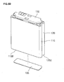
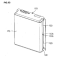
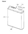
- a battery pack 100 includes a first battery cell 110, a second battery cell 120 electrically connected to the first battery cell 110, a protection circuit module (PCM) assembly 130 electrically connected to the first battery cell 110 and the second battery cell 120, a top case 150 accommodating the PCM assembly 130 and coupled to tops of the first and second battery cells 110 and 120, a bottom case 160 coupled to the lower sides of the first and second battery cells 110 and 120, and a label 170 wrapping lateral sides of the first and second battery cells 110 and 120.
- PCM protection circuit module
- the battery pack 100 further includes connector tabs 140 and 140' electrically connecting the PCM assembly 130 to the first battery cell 110 and the second battery cell 120.
- Each of the first battery cell 110 and the second battery cell 120 has an approximate hexahedron.
- the shapes of the first and second battery cells 110 and 120 are not limited to the hexahedron.
- the lateral sides of the first and second battery cells 110 and 120 include two wide lateral sides 110b and 120b and two narrow lateral sides 110c and 120c that face each other.
- Bottoms 110d and 120d of the first and second battery cells 110 and 120 are integrally formed with the wide lateral sides 110b and 120b and the narrow lateral sides 110c and 120c.
- the first battery cell 110 and the second battery cell 120 are bonded to each other in a way that one of the wide lateral sides 110b and one of the wide lateral sides 120b are facing and are bonded to each other.
- a spacer such as an insulator tape 180 is interposed between the wide lateral side 110b of the first battery cell 110 and the wide lateral side 120b of the second battery cell 120.
- the insulator tape 180 is a double-sided adhesive tape.
- the insulator tape 180 has a through-hole 181 formed in the middle thereof.
- the through-hole 181 has a rectangular shape, but its shape is not limited thereto.
- a space defined by the through-hole 181 acts as an escaping or release space that is preferably sized so as to accommodate the increased thicknesses of the first and second battery cells 110 and 120 occurring as a result of swelling of the battery cells 110, 120.
- the PCM assembly 130 includes a circuit board 131, an electric device 132 installed on the circuit board 131, and an external terminal 133 conducting current from the battery cells to the outside.
- the circuit board 131 has a rectangular shape with a width corresponding to the tops 110a and 120a of the two battery cells 110 and 120.
- the circuit board 131 has electrode through-holes 131a and 131b such that the negative terminal 111 of the first battery cell 110 and the negative terminal 121 of the second battery cell 120 are electrically connected to a negative terminal (not shown) of the circuit board 131.
- the circuit board 131 has cutaway portions 131c formed at four corners. Each of the cutaway portions 131c has an arc shape but the shape is not limited thereto.
- the cutaway portions 131c are formed to enable laser welding of the connector tabs 140 and 140' to the tops of the battery cells 110 and 120. Any shape enabling the laser welding may be employed in the cutaway portions 131c. Further, the overall configuration of the circuit board 131 may be selected to permit access to perform the laser welding of the connector tabs 140, 140'.
- the connector tabs 140 and 140' include board connection portions 141 and 141' installed on the circuit board 131, first cell connection portions 144 and 144' connected to the first battery cell 110, second cell connection portions 145 and 145' connected to the second battery cell 120, first connectors 142 and 142' connecting the board connection portions 141 and 141' to the first cell connection portions 144 and 144', and second connectors 143 and 143' connecting the board connection portions 141 and 141' to the second cell connection portions 145 and 145'.
- circuit board 131 is supported by the first connector tab 140 and the second connector tab 140' to be placed on the tops 110a and 120a of the first battery cell 110 and the second battery cell 120.
- the board connection portion 141 is parallel to the circuit board 131.
- the first connector 142 and the second connector 143 are integrally formed with the lower sides of the lateral edges of the board connection portion 141.
- the first cell connection portion 144 is integrally formed with an edge of the first connector 142 and the second connection portion 145 is integrally formed with an edge of the second connector 143.
- the first and second connection portions 144 and 145 are formed at the edges of the first and second connectors 142,143 to face each other by interposing the board connection portion 141 therebetween.
- the circuit board 131 is electrically connected to the two battery cells 110 and 120 at once by the connector tabs 140 and 140'.
- the first battery cell 110 is connected in parallel to the second battery cell 120.
- the first connector tab 140 and the second connector tab 140' electrically connect positive terminals of the first and second battery cells 110 and 120 (surfaces of the battery cells) to a positive terminal (not shown) of the circuit board 131.
- at least one of the first and second connector tabs 140 and 140' connects the first and second battery cells 110 and 120 to the circuit board 131.
- the first and second connector tabs 140 and 140' are made of nickel or nickel alloy with good electrical conductivity, but are not limited thereto.
- any one of the first and second connector tabs 140 and 140', which electrically connects the battery cells 110 and 120 to the circuit board 131 may be made of the nickel with good electrical conductivity and the other may not be made of an electrical conductor.
- the top case 150 includes a case body 151 and right and left frames 152 and 153.
- the case body 151 has a hexahedron shape with an internal space accommodating the PCM assembly 130, and the right and left frames 152 and 153 are integrally formed with right and left ends of the case body 151.
- the case body 151 includes a single planar surface 151a and four lateral sides 151b extending from the planar surface 151a.
- the planar surface 151a has external terminal through-holes 151c formed at a side and a water-sensitive label attachment 151d formed at the other side.
- Guide ribs 151e to which the label 170 is attached extend downwardly from the four lateral sides 151b.
- the right and left frames 152 and 153 are formed at the case body 151 in the vertical direction.
- the right and left frames 152 and 153 have protrusions 152a and 153a formed at inner middle portions thereof respectively.
- the protrusions 152a and 153a are formed in the longitudinal directions of the right and left frames 152 and 153.
- the protrusions 152a and 153a are inserted into gaps G defined by the narrow lateral sides 110c and 120c of the first and second battery cells 110 and 120 that are adhered to each other.
- the bottom case 160 includes a case body 161 and right and left frames 162 and 163.
- the case body 161 has a rectangular shape with a size sufficient to accommodate the bottoms of the first and second battery cells 110 and 120, and the right and left frames 162 and 163 are integrally formed with right and left edges of the case body 161.
- the case body 161 includes a single planar surface 161a and both lateral sides 161b extending from an edge of the planar surface 161a.
- Guide ribs 161e to which the label 170 is attached extend from the lateral sides 161b.
- the right and left frames 162 and 163 are formed at the case body 161 in the vertical direction.
- the right and left frames 162 and 163 have protrusions 162a and 163a formed at inner middle portions thereof respectively.
- the protrusions 162a and 163a may be formed in the longitudinal directions of the right and left frames 162 and 163.
- the protrusions 162a and 163a are inserted into gaps G defined by the narrow lateral sides 110c and 120c of the first and second battery cells 110 and 120 that are adhered to each other.
- Grooves 152b and 153b are formed at ends of the right and left frames 152 and 153 of the top case 150 respectively.
- Protrusions 162b and 163b are formed at ends of the right and left frames 162 and 163 of the bottom case 160 to be inserted into the grooves 152b and 153b respectively.
- the grooves 152b and 153b and the protrusions 162b and 163b may have any shapes enabling male- female coupling.
- the label 170 is attached to wrap a circumference of an assembly of the first and second battery cells 110 and 120, the top case 150, and the bottom case 160 at least one turn.
- the first and second battery cells 110 and 120 are securely assembled such that the wide lateral sides 110b and 120b are bonded to each other with the insulation tape 180 and are wrapped by the label 170.
- the label 170 is made of insulator and insulates the first and second battery cells 110 and 120 from the external device.
- An upper end of the label 170 wraps the guide ribs 151e of the top case 150 and a lower end of the label 170 wraps the guide ribs 161c of the bottom case 160.
- the top case 150 and the bottom case 160 are coupled with the first and second battery cells 110 and 120 by the label 170.
- the tops 110a and 120a of the first and second battery cells 110 and 120 are adhered with a second insulator tape 190. Due to the second insulator tape 190, the first and second battery cells 110 and 120 are insulated from the PCM assembly 130.
- the bottoms 110d and 120d of the first and second battery cells 110 and 120 are adhered with an adhesive tape 195.
- the adhesive tape 195 securely adheres to the first battery cell 110 and the second battery cell 120.
- the adhesive tape employs a double-sided tape.
- the bottom case 160 can be securely adhered to the bottoms 110d and 120d of the first and second battery cells 110 and 120.
- the water-sensitive label 175 is attached to the water-sensitive label attachment 151d formed on the top of the top case 150.
- the label 175 is a water sensitive label that turns color when the battery is exposed to water. In this way, the cause of failure of the device using the battery can be determined, e.g., the label can tell if an electronic device, such as a mobile phone, has been immersed in water.
- the two battery cells are controlled by the single PCM assembly during the charge and discharge so that inferior performance caused by overcharge and overdischarge is reduced.
- the first and second battery cells 110 and 120 are electrically connected to the PCM assembly 130 such that the negative terminals 111 and 121 of the battery cells 110 and 120 are electrically connected to negative terminals (not shown) of the circuit board 131.
- the first and second battery cells 110 and 120 are electrically connected to positive terminals (not shown) of the circuit board 131 by the first and second connector tabs 140 and 140'.
- the connector tabs 140 and 140' support the PCM assembly 130.
- the connector tabs 140 and 140' respectively have a bridge shape in which the board connection portions 141 and 141', the first and second connection portions 142, 142', 143, and 143', the first cell connection portions 144 and 144', and the second cell connection portions 145 and 145' are integrally formed with each other.
- connector tabs 140 and 140' of the battery pack 100 respectively are configured such that vertical relationships between the board connection portions 141 and 141', and the first and second connection portions 142, 142', 143, and 143' and the first and second cell connection portions 144, 144', 145, and 145' are established, another relationship may be possible.
- a battery pack according to another embodiment of the present invention will be described.
- a battery pack 200 includes a first battery cell 110 and a second battery cell 120 electrically connected to the first battery cell 110, a protection circuit module (PCM) assembly 130 electrically connected to the first and second battery cells 110 and 120, a top case 150 accommodating the PCM assembly 130 and coupled to tops of the first and second battery cells 110 and 120, a bottom case 160 coupled to the lower sides of the first and second battery cells 110 and 120, and a label 170 wrapping lateral sides of the first and second battery cells 110 and 120.
- This configuration is substantially the same to that of the battery pack 100 according to the embodiment of the present invention.
- the same reference numerals are assigned to the same elements and their description will be omitted.
- the battery pack 200 includes a connector tab, different from that of the battery pack 100 according to the previous embodiment of the present invention, electrically connecting the first and second battery cells 110 and 120 to the PCM assembly 130.
- the connector tab includes first and second connector tabs supporting both ends of the PCM assembly 130. Since the first and second connector tabs are identical to each other, a single connector tab 240 only will be described.
- the connector tab 240 in another embodiment of the present invention includes a board connection portion 241 installed in the PCM assembly 130, a first cell connection portion 244 connected to the first battery cell 110, a second cell connection portion 245 connected to the second battery cell 120, a first connection portion 242 connecting the board connection portion 241 to the first cell connection portion 244, and a second connection portion 243 connecting the board connection portion 241 to the second cell connection portion 245.
- the board connection portion 241 is parallel to the PCM assembly 130.
- the first and second connection portions 242, 243 are downwardly formed at edges of the board connection portion 241 in the vertical direction to the board connection portion 241.
- the first cell connection portion 244 is integrally formed with an edge of the first connection portion 242 or a slope portion 246 as described below
- the second cell connection portion 245 is integrally formed with an edge of the second connection portion 243 or a slope portion 247 as described below.
- the first and second cell connection portions 244 and 245 oppositely run from the edges of the first and second connection portions 242 and 243 with respect to the board connection portion 241.
- a slope portion 246 is formed between the first connection portion 242 and the first cell connection portion 244 and a slope portion 247 is formed between the second connection portion 243 and the second cell connection portion 245.
- the slope portions 246 and 247 extend from the lower sides of the first and second connection portions 242 and 243 to the first and second cell connection portions 244 and 245 at a preset angle ⁇ .
- the angle ⁇ is approximately 20 degrees to 70 degrees.
- the first and second battery cells 110 and 120 when the first and second battery cells 110 and 120 swell, the first and second battery cells 110 and 120, as illustrated in FIG. 6B , are spaced away from each other with respect to the insulator tape 180.
- the connector tab 240 is deformed such that the first and second connection portions 242 and 243 are moved apart from the edges of the board connection portion 241 by the slopes 246 and 247.
- connection portions 242 and 243 of the connector tab 240 moved away from each other as the gap, between the battery cells, increases due to the swelling of the first and second battery cells 110 and 120.
- the first and second cell connection portions 244 and 245 of the connector tab 240 are less likely to be separated from the tops 110a and the 120a of the first and second battery cells 110 and 120, so that the welded state can be maintained and the inferior welds do not occur.
- the angle ⁇ of the slopes 246 and 247 is less than 20 degrees, since an angle between each of the connection portions 242 and 243 and each of the slopes 246 and 247 is small and the connection portions 242 and 243 do not substantially spread, the first and second cell connection portions 244 and 245 are more likely to be separated from the tops 110a and 120a of the first and second battery cells 110 and 120.
- the angle ⁇ of the slopes 246 and 247 is greater than 70 degrees, since an angle between each of the first and second cell connection portions 244 and 245 and each of the slopes 246 and 247 is small and the connection portions 242 and 243 do not spread, the first and second cell connection portions 244 and 245 are more likely to be separated from the tops 110a and 120a of the first and second battery cells 110 and 120.
- a battery pack 300 according to still another embodiment of the present invention will described as follows.
- the battery pack 300 since the battery pack 300 according to still another embodiment of the present invention is established by a connector tab, the battery pack 300 will be described by concentrating on the connector tab.
- a connector tab 340 in the battery pack 300 includes a board connection portion 341 installed in the PCM assembly 130, a first cell connection portion 344 electrically connected to the first battery cell 110, a second cell connection portion 345 electrically connected to the second battery cell 120, a first connection portion 342 electrically connecting the board connection portion 341 to the first cell connection portion 344, and a second connection portion 343 electrically connecting the board connection portion 341 to the second cell connection portion 345.
- the board connection portion 341 is parallel to the PCM assembly 130.
- the first and second connection portions 342 and 343 are obliquely connected to edges of the board connection portion 341.
- the first cell connection portion 344 is integrally formed with an edge of the first connection portion 342, and the second cell connection portion 345 is integrally formed with an edge of the second connection portion 343.
- the first and second cell connection portions 344 and 345 oppositely run from the edges of the first and second connection portions 342 and 343 with respect to the board connection portion 341, respectively.
- the first and second connection portions 342 and 343 extend from the edges of the board connection portion 341 outwardly oblique to the vertical direction.
- the connector tab 240 of the battery pack 200 according to another embodiment of the present invention is configured such that the slopes 246 and 247 are formed at some portions of the first and second connection portions 242 and 243, and in still another embodiment, the first and second connection portions 342 and 343 wholly form the slopes.
- the first and second connection portions 342 and 343 extend from the edges of the board connection portion 341 toward the first and second cell connection portions 344 and 345 at a preset angle ⁇ , respectively.
- the preset angle ⁇ ranges approximately from 20 degrees to 70 degrees.
- the angle ⁇ is less than 20 degrees or greater than 70 degrees, a gap between the connection portions 342 and 343 does not increase in a case that an external force is exerted, so that the contact inferiority occurs.
- the connector tab 340 spreads laterally with respect to the board connection portion 341.
- first and second connection portions 342 and 343 of the connector tab 340 are moved away from each other as the gap increases due to the swelling of the first and second battery cells 110 and 120. Consequently, the first and second cell connection portions 344 and 345 of the connector tab 340 are less likely to be separated from the tops 110a and 120a of the first and second battery cells 110 and 120 while maintaining the welded state, so that the contact inferiority does not occur.
- a battery pack 400 according to still another embodiment of the present invention will be described.
- the battery pack 400 since the battery pack 400 according to still another embodiment of the present invention is established by a connector tab, the battery pack 400 will be described by concentrating on the connector tab.
- a connector tab 440 in the battery pack 400 includes a board connection portion 441 installed in the PCM assembly 130, a first cell connection portion 444 electrically connected to the first battery cell 110, a second cell connection portion 445 electrically connected to the second battery cell 120, a first connection portion 442 electrically connecting the board connection portion 441 to the first cell connection portion 444, and a second connection portion 443 electrically connecting the board connection portion 441 to the second cell connection portion 445.
- the board connection portion 441 is parallel to the PCM assembly 130.
- the first and second connection portions 442 and 443 are rounded at edges of the board connection portion 441.
- the first cell connection portion 444 is integrally formed with an edge of the first connection portion 442, and the second cell connection portion 445 is integrally formed with an edge of the second connection portion 443.
- the first and second cell connection portions 444 and 445 oppositely run from the edges of the first and second connection portions 442 and 443 with respect to the board connection portion 441, respectively.
- the first and second connection portions 442 and 443 of the connector tab 440 are rounded.
- the first and second connection portions 442 and 443 are respectively bent at the edges of the board connection portion 441 opposite to the positions where the first and second cell connection portions 444 and 445 and bent again from their middle portions toward the positions of the first and second cell connection portions 444 and 445.
- first and second connection portions 442 and 443 of the connector tab 440 are moved apart from each other as the gap increase due to the swelling of the first and second battery cells 110 and 120. Consequently, the first and second cell connection portions 444 and 445 of the connector tab 440 are less likely to be separated from the tops 110a and 120a of the first and second battery cells 110 and 120 while maintaining the welded state, so that the contact inferiority is prevented.
Applications Claiming Priority (2)
| Application Number | Priority Date | Filing Date | Title |
|---|---|---|---|
| US7454908P | 2008-06-20 | 2008-06-20 | |
| US12/356,247 US8999536B2 (en) | 2008-06-20 | 2009-01-20 | Battery pack |
Publications (3)
| Publication Number | Publication Date |
|---|---|
| EP2136451A2 EP2136451A2 (en) | 2009-12-23 |
| EP2136451A3 EP2136451A3 (en) | 2013-03-27 |
| EP2136451B1 true EP2136451B1 (en) | 2014-04-30 |
Family
ID=40939057
Family Applications (1)
| Application Number | Title | Priority Date | Filing Date |
|---|---|---|---|
| EP09162879.2A Active EP2136451B1 (en) | 2008-06-20 | 2009-06-16 | Battery pack |
Country Status (5)
| Country | Link |
|---|---|
| US (1) | US8999536B2 (ko) |
| EP (1) | EP2136451B1 (ko) |
| JP (1) | JP5191957B2 (ko) |
| KR (1) | KR101094037B1 (ko) |
| CN (1) | CN101609902B (ko) |
Families Citing this family (35)
| Publication number | Priority date | Publication date | Assignee | Title |
|---|---|---|---|---|
| KR100876266B1 (ko) * | 2007-09-28 | 2008-12-26 | 삼성에스디아이 주식회사 | 이차전지 |
| KR101009567B1 (ko) * | 2008-12-05 | 2011-01-18 | 삼성에스디아이 주식회사 | 배터리 팩 |
| KR101122904B1 (ko) * | 2009-12-18 | 2012-03-20 | 삼성에스디아이 주식회사 | 배터리 팩 |
| JP2013200940A (ja) * | 2010-06-14 | 2013-10-03 | Toyota Motor Corp | 蓄電装置 |
| KR101152443B1 (ko) | 2010-07-12 | 2012-06-01 | 삼성에스디아이 주식회사 | 배터리 팩 |
| KR101199108B1 (ko) * | 2010-07-12 | 2012-11-09 | 삼성에스디아이 주식회사 | 이차 전지 케이스 및 이를 포함하는 이차 전지 |
| US8343651B2 (en) * | 2010-07-16 | 2013-01-01 | Samsung Sdi Co., Ltd. | Battery pack |
| US9065085B2 (en) | 2011-04-19 | 2015-06-23 | Samsung Sdi Co., Ltd. | Battery pack |
| US9017836B2 (en) | 2011-07-06 | 2015-04-28 | Samsung Sdi Co., Ltd. | Battery pack |
| JP5966591B2 (ja) | 2012-05-15 | 2016-08-10 | ソニー株式会社 | バッテリパック |
| KR101908587B1 (ko) * | 2012-06-12 | 2018-10-17 | 에스케이이노베이션 주식회사 | 조립이 용이한 이차전지모듈 |
| JP5915403B2 (ja) * | 2012-06-18 | 2016-05-11 | 株式会社Gsユアサ | 組電池 |
| KR101908452B1 (ko) | 2012-06-28 | 2018-10-17 | 에스케이이노베이션 주식회사 | 조립이 용이한 일체형 이차전지모듈 |
| KR102028168B1 (ko) * | 2012-08-20 | 2019-10-02 | 삼성에스디아이 주식회사 | 외장부재를 포함하는 배터리 팩 |
| KR101397028B1 (ko) * | 2012-09-13 | 2014-05-20 | 삼성에스디아이 주식회사 | 배터리 팩 |
| KR102052588B1 (ko) * | 2013-08-13 | 2019-12-05 | 삼성에스디아이 주식회사 | 이차전지 팩 |
| KR102222888B1 (ko) * | 2014-04-09 | 2021-03-04 | 삼성에스디아이 주식회사 | 배터리모듈 |
| USD762566S1 (en) * | 2014-09-08 | 2016-08-02 | Parrot Drones | Battery for a headphone |
| USD764401S1 (en) * | 2014-09-08 | 2016-08-23 | Parrot Drone | Battery for a remote-controlled toy |
| KR102263200B1 (ko) | 2015-01-19 | 2021-06-10 | 삼성에스디아이 주식회사 | 배터리 팩 |
| KR102324344B1 (ko) * | 2015-01-27 | 2021-11-10 | 삼성에스디아이 주식회사 | 배터리 팩 |
| USD788698S1 (en) * | 2015-02-18 | 2017-06-06 | Limefuel, LLC | Rechargeable battery device |
| USD780112S1 (en) * | 2015-02-18 | 2017-02-28 | Limefuel, LLC | Rechargeable battery device |
| USD815032S1 (en) * | 2015-02-20 | 2018-04-10 | Limefuel, LLC | Rechargeable battery device |
| US10164296B2 (en) | 2015-03-12 | 2018-12-25 | Johnson Controls Technology Company | Battery module separator plates |
| JP6585726B2 (ja) * | 2015-10-02 | 2019-10-02 | 日立オートモティブシステムズ株式会社 | 組電池 |
| CN106972144B (zh) * | 2016-01-14 | 2023-03-17 | 宁德时代新能源科技股份有限公司 | 二次电池 |
| JP6418257B2 (ja) * | 2017-01-25 | 2018-11-07 | ソニー株式会社 | バッテリパック |
| KR102422515B1 (ko) * | 2017-10-19 | 2022-07-19 | 삼성에스디아이 주식회사 | 배터리 팩 |
| CN109510255B (zh) * | 2018-10-31 | 2021-08-27 | 深圳欣旺达智能科技有限公司 | 双电池快充结构和移动终端 |
| KR20200053981A (ko) * | 2018-11-09 | 2020-05-19 | 주식회사 아모그린텍 | 배터리 압력 감지 장치 |
| JP2021061152A (ja) * | 2019-10-07 | 2021-04-15 | シャープ株式会社 | 電池パックおよび電子機器 |
| US11832428B2 (en) | 2021-07-19 | 2023-11-28 | Google Llc | Battery with electromagnetic interference shielding |
| CN113451630A (zh) * | 2021-07-27 | 2021-09-28 | 孟琳 | 一种液流电池系统的电堆叠层封装方法及设备 |
| JP2024501592A (ja) * | 2021-11-30 | 2024-01-15 | 寧徳時代新能源科技股▲分▼有限公司 | 電池及びその製造方法と製造設備、電力消費装置 |
Family Cites Families (23)
| Publication number | Priority date | Publication date | Assignee | Title |
|---|---|---|---|---|
| ES2092237T3 (es) * | 1992-12-22 | 1996-11-16 | Honda Motor Co Ltd | Bateria con estructura antioxidante. |
| JP4406940B2 (ja) | 1998-02-24 | 2010-02-03 | ソニー株式会社 | 単電池の電気的接続装置 |
| GB9900396D0 (en) | 1999-01-08 | 1999-02-24 | Danionics As | Arrangements of electrochemical cells |
| KR100322102B1 (ko) | 1999-12-14 | 2002-02-06 | 김순택 | 배터리의 연결단자 |
| JP3614767B2 (ja) | 2000-10-20 | 2005-01-26 | 松下電器産業株式会社 | 電気製品の外装体形成方法 |
| JP3877623B2 (ja) | 2002-03-28 | 2007-02-07 | 三洋電機株式会社 | パック電池の製造方法 |
| KR100958647B1 (ko) | 2002-12-18 | 2010-05-20 | 삼성에스디아이 주식회사 | 파우치형 이차전지 유니트 |
| JP3806696B2 (ja) | 2003-02-14 | 2006-08-09 | 三洋電機株式会社 | パック電池 |
| JP4301929B2 (ja) | 2003-12-10 | 2009-07-22 | 三洋電機株式会社 | 電池パック |
| WO2005078825A1 (en) * | 2004-02-13 | 2005-08-25 | Lg Chem, Ltd. | Battery pack of improved structure |
| WO2005078021A1 (ja) | 2004-02-18 | 2005-08-25 | Kawamura Institute Of Chemical Research | 有機無機複合ナノファイバ、有機無機複合構造体及びこれらの製造方法 |
| JP4480456B2 (ja) | 2004-05-12 | 2010-06-16 | 埼玉日本電気株式会社 | 電池パック及びそれを用いた携帯通信端末 |
| JP2006040775A (ja) | 2004-07-29 | 2006-02-09 | Tocad Energy Co Ltd | 電池の組み合わせ構造 |
| KR100601514B1 (ko) | 2004-09-24 | 2006-07-19 | 삼성에스디아이 주식회사 | 배터리 팩의 도전성 플레이트 구조 |
| JP4716719B2 (ja) | 2004-12-03 | 2011-07-06 | 三洋電機株式会社 | 電池パック |
| TWI328892B (en) * | 2005-08-12 | 2010-08-11 | Sony Corp | Secondary battery |
| JP5011678B2 (ja) * | 2005-08-12 | 2012-08-29 | ソニー株式会社 | 二次電池 |
| JP5054905B2 (ja) | 2005-09-05 | 2012-10-24 | 株式会社オートネットワーク技術研究所 | バッテリ出力端子と端子金具の接続方法 |
| KR100850866B1 (ko) | 2005-12-27 | 2008-08-07 | 주식회사 엘지화학 | 전지팩 제조용 프레임 부재 |
| KR100719723B1 (ko) | 2005-12-29 | 2007-05-17 | 삼성에스디아이 주식회사 | 도전성 플레이트 및 이를 이용한 팩 전지 |
| KR20070108755A (ko) | 2006-05-08 | 2007-11-13 | 삼성에스디아이 주식회사 | 배터리 팩 |
| KR100873308B1 (ko) | 2006-06-05 | 2008-12-12 | 주식회사 엘지화학 | 두 개 이상의 유닛 셀들을 포함하고 있는 고용량 전지셀 |
| KR100984133B1 (ko) | 2008-04-11 | 2010-09-28 | 삼성에스디아이 주식회사 | 배터리 팩 |
-
2009
- 2009-01-20 US US12/356,247 patent/US8999536B2/en active Active
- 2009-03-10 KR KR1020090020215A patent/KR101094037B1/ko active IP Right Grant
- 2009-06-16 EP EP09162879.2A patent/EP2136451B1/en active Active
- 2009-06-18 JP JP2009145601A patent/JP5191957B2/ja active Active
- 2009-06-18 CN CN2009101424857A patent/CN101609902B/zh active Active
Also Published As
| Publication number | Publication date |
|---|---|
| CN101609902A (zh) | 2009-12-23 |
| CN101609902B (zh) | 2012-02-22 |
| JP5191957B2 (ja) | 2013-05-08 |
| JP2010003691A (ja) | 2010-01-07 |
| KR101094037B1 (ko) | 2011-12-19 |
| EP2136451A3 (en) | 2013-03-27 |
| US8999536B2 (en) | 2015-04-07 |
| EP2136451A2 (en) | 2009-12-23 |
| KR20090132490A (ko) | 2009-12-30 |
| US20090317703A1 (en) | 2009-12-24 |
Similar Documents
| Publication | Publication Date | Title |
|---|---|---|
| EP2136451B1 (en) | Battery pack | |
| US7611797B2 (en) | Lithium secondary battery with safety device | |
| EP2453500B1 (en) | A rechargeable battery, method of assembling a rechargeably battery, and a rechargeable battery module | |
| KR101059756B1 (ko) | 신규한 구조의 이차전지 팩 | |
| KR100870349B1 (ko) | 보호회로기판의 접속단자 및 그를 이용한 이차전지 | |
| CN102376931B (zh) | 可再充电电池、电池模块和可再充电电池的电极端子组件 | |
| JP4749130B2 (ja) | 二次電池及びその形成方法 | |
| KR101009567B1 (ko) | 배터리 팩 | |
| KR101001315B1 (ko) | 우수한 에너지 밀도의 이차전지 팩 및 그것을 위한 pcm어셈블리 | |
| JP4187685B2 (ja) | 二次電池 | |
| JP4499648B2 (ja) | リチウムイオン二次電池 | |
| EP2302718B1 (en) | Secondary battery | |
| KR101441524B1 (ko) | 신규한 구조의 이차전지 팩 | |
| US8481183B2 (en) | Secondary battery | |
| WO2021023060A1 (zh) | 二次电池及电池包 | |
| KR101198026B1 (ko) | 신규한 구조의 이차전지 팩 | |
| EP2328200B1 (en) | Battery assembly | |
| US8216706B2 (en) | Battery pack | |
| KR101432224B1 (ko) | 신규한 구조의 내장형 이차전지 팩 | |
| EP2273585B1 (en) | Battery pack | |
| KR101057578B1 (ko) | 폴리머 전지팩 | |
| KR101057525B1 (ko) | 배터리 팩 | |
| KR101130048B1 (ko) | 신규한 구조의 pcm 어셈블리를 포함하고 있는 이차전지팩 | |
| CN218975498U (zh) | 电池以及电子设备 | |
| US8741452B2 (en) | Secondary battery |
Legal Events
| Date | Code | Title | Description |
|---|---|---|---|
| PUAI | Public reference made under article 153(3) epc to a published international application that has entered the european phase |
Free format text: ORIGINAL CODE: 0009012 |
|
| 17P | Request for examination filed |
Effective date: 20090616 |
|
| AK | Designated contracting states |
Kind code of ref document: A2 Designated state(s): AT BE BG CH CY CZ DE DK EE ES FI FR GB GR HR HU IE IS IT LI LT LU LV MC MK MT NL NO PL PT RO SE SI SK TR |
|
| PUAL | Search report despatched |
Free format text: ORIGINAL CODE: 0009013 |
|
| AK | Designated contracting states |
Kind code of ref document: A3 Designated state(s): AT BE BG CH CY CZ DE DK EE ES FI FR GB GR HR HU IE IS IT LI LT LU LV MC MK MT NL NO PL PT RO SE SI SK TR |
|
| RIC1 | Information provided on ipc code assigned before grant |
Ipc: H02J 7/00 20060101AFI20130221BHEP Ipc: H01M 2/20 20060101ALI20130221BHEP Ipc: H01M 10/42 20060101ALI20130221BHEP |
|
| GRAP | Despatch of communication of intention to grant a patent |
Free format text: ORIGINAL CODE: EPIDOSNIGR1 |
|
| INTG | Intention to grant announced |
Effective date: 20140122 |
|
| GRAS | Grant fee paid |
Free format text: ORIGINAL CODE: EPIDOSNIGR3 |
|
| GRAA | (expected) grant |
Free format text: ORIGINAL CODE: 0009210 |
|
| AK | Designated contracting states |
Kind code of ref document: B1 Designated state(s): AT BE BG CH CY CZ DE DK EE ES FI FR GB GR HR HU IE IS IT LI LT LU LV MC MK MT NL NO PL PT RO SE SI SK TR |
|
| REG | Reference to a national code |
Ref country code: GB Ref legal event code: FG4D Ref country code: CH Ref legal event code: EP |
|
| RAP2 | Party data changed (patent owner data changed or rights of a patent transferred) |
Owner name: SAMSUNG SDI CO., LTD. |
|
| REG | Reference to a national code |
Ref country code: AT Ref legal event code: REF Ref document number: 665679 Country of ref document: AT Kind code of ref document: T Effective date: 20140515 |
|
| REG | Reference to a national code |
Ref country code: IE Ref legal event code: FG4D |
|
| REG | Reference to a national code |
Ref country code: DE Ref legal event code: R096 Ref document number: 602009023632 Country of ref document: DE Effective date: 20140612 |
|
| REG | Reference to a national code |
Ref country code: AT Ref legal event code: MK05 Ref document number: 665679 Country of ref document: AT Kind code of ref document: T Effective date: 20140430 |
|
| REG | Reference to a national code |
Ref country code: LT Ref legal event code: MG4D |
|
| REG | Reference to a national code |
Ref country code: NL Ref legal event code: VDEP Effective date: 20140430 |
|
| PG25 | Lapsed in a contracting state [announced via postgrant information from national office to epo] |
Ref country code: NL Free format text: LAPSE BECAUSE OF FAILURE TO SUBMIT A TRANSLATION OF THE DESCRIPTION OR TO PAY THE FEE WITHIN THE PRESCRIBED TIME-LIMIT Effective date: 20140430 Ref country code: CY Free format text: LAPSE BECAUSE OF FAILURE TO SUBMIT A TRANSLATION OF THE DESCRIPTION OR TO PAY THE FEE WITHIN THE PRESCRIBED TIME-LIMIT Effective date: 20140430 Ref country code: FI Free format text: LAPSE BECAUSE OF FAILURE TO SUBMIT A TRANSLATION OF THE DESCRIPTION OR TO PAY THE FEE WITHIN THE PRESCRIBED TIME-LIMIT Effective date: 20140430 Ref country code: BG Free format text: LAPSE BECAUSE OF FAILURE TO SUBMIT A TRANSLATION OF THE DESCRIPTION OR TO PAY THE FEE WITHIN THE PRESCRIBED TIME-LIMIT Effective date: 20140730 Ref country code: IS Free format text: LAPSE BECAUSE OF FAILURE TO SUBMIT A TRANSLATION OF THE DESCRIPTION OR TO PAY THE FEE WITHIN THE PRESCRIBED TIME-LIMIT Effective date: 20140830 Ref country code: GR Free format text: LAPSE BECAUSE OF FAILURE TO SUBMIT A TRANSLATION OF THE DESCRIPTION OR TO PAY THE FEE WITHIN THE PRESCRIBED TIME-LIMIT Effective date: 20140731 Ref country code: NO Free format text: LAPSE BECAUSE OF FAILURE TO SUBMIT A TRANSLATION OF THE DESCRIPTION OR TO PAY THE FEE WITHIN THE PRESCRIBED TIME-LIMIT Effective date: 20140730 Ref country code: LT Free format text: LAPSE BECAUSE OF FAILURE TO SUBMIT A TRANSLATION OF THE DESCRIPTION OR TO PAY THE FEE WITHIN THE PRESCRIBED TIME-LIMIT Effective date: 20140430 |
|
| PG25 | Lapsed in a contracting state [announced via postgrant information from national office to epo] |
Ref country code: HR Free format text: LAPSE BECAUSE OF FAILURE TO SUBMIT A TRANSLATION OF THE DESCRIPTION OR TO PAY THE FEE WITHIN THE PRESCRIBED TIME-LIMIT Effective date: 20140430 Ref country code: PL Free format text: LAPSE BECAUSE OF FAILURE TO SUBMIT A TRANSLATION OF THE DESCRIPTION OR TO PAY THE FEE WITHIN THE PRESCRIBED TIME-LIMIT Effective date: 20140430 Ref country code: SE Free format text: LAPSE BECAUSE OF FAILURE TO SUBMIT A TRANSLATION OF THE DESCRIPTION OR TO PAY THE FEE WITHIN THE PRESCRIBED TIME-LIMIT Effective date: 20140430 Ref country code: LV Free format text: LAPSE BECAUSE OF FAILURE TO SUBMIT A TRANSLATION OF THE DESCRIPTION OR TO PAY THE FEE WITHIN THE PRESCRIBED TIME-LIMIT Effective date: 20140430 Ref country code: ES Free format text: LAPSE BECAUSE OF FAILURE TO SUBMIT A TRANSLATION OF THE DESCRIPTION OR TO PAY THE FEE WITHIN THE PRESCRIBED TIME-LIMIT Effective date: 20140430 Ref country code: AT Free format text: LAPSE BECAUSE OF FAILURE TO SUBMIT A TRANSLATION OF THE DESCRIPTION OR TO PAY THE FEE WITHIN THE PRESCRIBED TIME-LIMIT Effective date: 20140430 |
|
| PG25 | Lapsed in a contracting state [announced via postgrant information from national office to epo] |
Ref country code: PT Free format text: LAPSE BECAUSE OF FAILURE TO SUBMIT A TRANSLATION OF THE DESCRIPTION OR TO PAY THE FEE WITHIN THE PRESCRIBED TIME-LIMIT Effective date: 20140901 |
|
| PG25 | Lapsed in a contracting state [announced via postgrant information from national office to epo] |
Ref country code: EE Free format text: LAPSE BECAUSE OF FAILURE TO SUBMIT A TRANSLATION OF THE DESCRIPTION OR TO PAY THE FEE WITHIN THE PRESCRIBED TIME-LIMIT Effective date: 20140430 Ref country code: DK Free format text: LAPSE BECAUSE OF FAILURE TO SUBMIT A TRANSLATION OF THE DESCRIPTION OR TO PAY THE FEE WITHIN THE PRESCRIBED TIME-LIMIT Effective date: 20140430 Ref country code: LU Free format text: LAPSE BECAUSE OF FAILURE TO SUBMIT A TRANSLATION OF THE DESCRIPTION OR TO PAY THE FEE WITHIN THE PRESCRIBED TIME-LIMIT Effective date: 20140616 Ref country code: CZ Free format text: LAPSE BECAUSE OF FAILURE TO SUBMIT A TRANSLATION OF THE DESCRIPTION OR TO PAY THE FEE WITHIN THE PRESCRIBED TIME-LIMIT Effective date: 20140430 Ref country code: SK Free format text: LAPSE BECAUSE OF FAILURE TO SUBMIT A TRANSLATION OF THE DESCRIPTION OR TO PAY THE FEE WITHIN THE PRESCRIBED TIME-LIMIT Effective date: 20140430 Ref country code: MC Free format text: LAPSE BECAUSE OF FAILURE TO SUBMIT A TRANSLATION OF THE DESCRIPTION OR TO PAY THE FEE WITHIN THE PRESCRIBED TIME-LIMIT Effective date: 20140430 Ref country code: RO Free format text: LAPSE BECAUSE OF FAILURE TO SUBMIT A TRANSLATION OF THE DESCRIPTION OR TO PAY THE FEE WITHIN THE PRESCRIBED TIME-LIMIT Effective date: 20140430 Ref country code: BE Free format text: LAPSE BECAUSE OF FAILURE TO SUBMIT A TRANSLATION OF THE DESCRIPTION OR TO PAY THE FEE WITHIN THE PRESCRIBED TIME-LIMIT Effective date: 20140430 |
|
| REG | Reference to a national code |
Ref country code: CH Ref legal event code: PL |
|
| REG | Reference to a national code |
Ref country code: DE Ref legal event code: R097 Ref document number: 602009023632 Country of ref document: DE |
|
| PLBE | No opposition filed within time limit |
Free format text: ORIGINAL CODE: 0009261 |
|
| STAA | Information on the status of an ep patent application or granted ep patent |
Free format text: STATUS: NO OPPOSITION FILED WITHIN TIME LIMIT |
|
| REG | Reference to a national code |
Ref country code: IE Ref legal event code: MM4A |
|
| PG25 | Lapsed in a contracting state [announced via postgrant information from national office to epo] |
Ref country code: IT Free format text: LAPSE BECAUSE OF FAILURE TO SUBMIT A TRANSLATION OF THE DESCRIPTION OR TO PAY THE FEE WITHIN THE PRESCRIBED TIME-LIMIT Effective date: 20140430 |
|
| 26N | No opposition filed |
Effective date: 20150202 |
|
| PG25 | Lapsed in a contracting state [announced via postgrant information from national office to epo] |
Ref country code: CH Free format text: LAPSE BECAUSE OF NON-PAYMENT OF DUE FEES Effective date: 20140630 Ref country code: IE Free format text: LAPSE BECAUSE OF NON-PAYMENT OF DUE FEES Effective date: 20140616 Ref country code: LI Free format text: LAPSE BECAUSE OF NON-PAYMENT OF DUE FEES Effective date: 20140630 |
|
| REG | Reference to a national code |
Ref country code: DE Ref legal event code: R097 Ref document number: 602009023632 Country of ref document: DE Effective date: 20150202 |
|
| PG25 | Lapsed in a contracting state [announced via postgrant information from national office to epo] |
Ref country code: SI Free format text: LAPSE BECAUSE OF FAILURE TO SUBMIT A TRANSLATION OF THE DESCRIPTION OR TO PAY THE FEE WITHIN THE PRESCRIBED TIME-LIMIT Effective date: 20140430 |
|
| PG25 | Lapsed in a contracting state [announced via postgrant information from national office to epo] |
Ref country code: MT Free format text: LAPSE BECAUSE OF FAILURE TO SUBMIT A TRANSLATION OF THE DESCRIPTION OR TO PAY THE FEE WITHIN THE PRESCRIBED TIME-LIMIT Effective date: 20140430 |
|
| REG | Reference to a national code |
Ref country code: FR Ref legal event code: PLFP Year of fee payment: 8 |
|
| PG25 | Lapsed in a contracting state [announced via postgrant information from national office to epo] |
Ref country code: TR Free format text: LAPSE BECAUSE OF FAILURE TO SUBMIT A TRANSLATION OF THE DESCRIPTION OR TO PAY THE FEE WITHIN THE PRESCRIBED TIME-LIMIT Effective date: 20140430 Ref country code: HU Free format text: LAPSE BECAUSE OF FAILURE TO SUBMIT A TRANSLATION OF THE DESCRIPTION OR TO PAY THE FEE WITHIN THE PRESCRIBED TIME-LIMIT; INVALID AB INITIO Effective date: 20090616 |
|
| REG | Reference to a national code |
Ref country code: FR Ref legal event code: PLFP Year of fee payment: 9 |
|
| REG | Reference to a national code |
Ref country code: FR Ref legal event code: PLFP Year of fee payment: 10 |
|
| PG25 | Lapsed in a contracting state [announced via postgrant information from national office to epo] |
Ref country code: MK Free format text: LAPSE BECAUSE OF FAILURE TO SUBMIT A TRANSLATION OF THE DESCRIPTION OR TO PAY THE FEE WITHIN THE PRESCRIBED TIME-LIMIT Effective date: 20140430 |
|
| P01 | Opt-out of the competence of the unified patent court (upc) registered |
Effective date: 20230528 |
|
| PGFP | Annual fee paid to national office [announced via postgrant information from national office to epo] |
Ref country code: FR Payment date: 20230523 Year of fee payment: 15 Ref country code: DE Payment date: 20230524 Year of fee payment: 15 |
|
| PGFP | Annual fee paid to national office [announced via postgrant information from national office to epo] |
Ref country code: GB Payment date: 20230518 Year of fee payment: 15 |