EP2136451B1 - Battery pack - Google Patents
Battery pack Download PDFInfo
- Publication number
- EP2136451B1 EP2136451B1 EP09162879.2A EP09162879A EP2136451B1 EP 2136451 B1 EP2136451 B1 EP 2136451B1 EP 09162879 A EP09162879 A EP 09162879A EP 2136451 B1 EP2136451 B1 EP 2136451B1
- Authority
- EP
- European Patent Office
- Prior art keywords
- battery cells
- protection circuit
- battery
- assembly
- mounting portion
- Prior art date
- Legal status (The legal status is an assumption and is not a legal conclusion. Google has not performed a legal analysis and makes no representation as to the accuracy of the status listed.)
- Active
Links
Images


Classifications
-
- H—ELECTRICITY
- H01—ELECTRIC ELEMENTS
- H01M—PROCESSES OR MEANS, e.g. BATTERIES, FOR THE DIRECT CONVERSION OF CHEMICAL ENERGY INTO ELECTRICAL ENERGY
- H01M50/00—Constructional details or processes of manufacture of the non-active parts of electrochemical cells other than fuel cells, e.g. hybrid cells
- H01M50/20—Mountings; Secondary casings or frames; Racks, modules or packs; Suspension devices; Shock absorbers; Transport or carrying devices; Holders
-
- H—ELECTRICITY
- H01—ELECTRIC ELEMENTS
- H01M—PROCESSES OR MEANS, e.g. BATTERIES, FOR THE DIRECT CONVERSION OF CHEMICAL ENERGY INTO ELECTRICAL ENERGY
- H01M10/00—Secondary cells; Manufacture thereof
- H01M10/42—Methods or arrangements for servicing or maintenance of secondary cells or secondary half-cells
- H01M10/425—Structural combination with electronic components, e.g. electronic circuits integrated to the outside of the casing
-
- H—ELECTRICITY
- H01—ELECTRIC ELEMENTS
- H01M—PROCESSES OR MEANS, e.g. BATTERIES, FOR THE DIRECT CONVERSION OF CHEMICAL ENERGY INTO ELECTRICAL ENERGY
- H01M10/00—Secondary cells; Manufacture thereof
- H01M10/42—Methods or arrangements for servicing or maintenance of secondary cells or secondary half-cells
- H01M10/4207—Methods or arrangements for servicing or maintenance of secondary cells or secondary half-cells for several batteries or cells simultaneously or sequentially
-
- H—ELECTRICITY
- H01—ELECTRIC ELEMENTS
- H01M—PROCESSES OR MEANS, e.g. BATTERIES, FOR THE DIRECT CONVERSION OF CHEMICAL ENERGY INTO ELECTRICAL ENERGY
- H01M50/00—Constructional details or processes of manufacture of the non-active parts of electrochemical cells other than fuel cells, e.g. hybrid cells
- H01M50/20—Mountings; Secondary casings or frames; Racks, modules or packs; Suspension devices; Shock absorbers; Transport or carrying devices; Holders
- H01M50/204—Racks, modules or packs for multiple batteries or multiple cells
- H01M50/207—Racks, modules or packs for multiple batteries or multiple cells characterised by their shape
- H01M50/211—Racks, modules or packs for multiple batteries or multiple cells characterised by their shape adapted for pouch cells
-
- H—ELECTRICITY
- H01—ELECTRIC ELEMENTS
- H01M—PROCESSES OR MEANS, e.g. BATTERIES, FOR THE DIRECT CONVERSION OF CHEMICAL ENERGY INTO ELECTRICAL ENERGY
- H01M50/00—Constructional details or processes of manufacture of the non-active parts of electrochemical cells other than fuel cells, e.g. hybrid cells
- H01M50/20—Mountings; Secondary casings or frames; Racks, modules or packs; Suspension devices; Shock absorbers; Transport or carrying devices; Holders
- H01M50/271—Lids or covers for the racks or secondary casings
-
- H—ELECTRICITY
- H01—ELECTRIC ELEMENTS
- H01M—PROCESSES OR MEANS, e.g. BATTERIES, FOR THE DIRECT CONVERSION OF CHEMICAL ENERGY INTO ELECTRICAL ENERGY
- H01M50/00—Constructional details or processes of manufacture of the non-active parts of electrochemical cells other than fuel cells, e.g. hybrid cells
- H01M50/20—Mountings; Secondary casings or frames; Racks, modules or packs; Suspension devices; Shock absorbers; Transport or carrying devices; Holders
- H01M50/284—Mountings; Secondary casings or frames; Racks, modules or packs; Suspension devices; Shock absorbers; Transport or carrying devices; Holders with incorporated circuit boards, e.g. printed circuit boards [PCB]
- H01M50/287—Fixing of circuit boards to lids or covers
-
- H—ELECTRICITY
- H01—ELECTRIC ELEMENTS
- H01M—PROCESSES OR MEANS, e.g. BATTERIES, FOR THE DIRECT CONVERSION OF CHEMICAL ENERGY INTO ELECTRICAL ENERGY
- H01M50/00—Constructional details or processes of manufacture of the non-active parts of electrochemical cells other than fuel cells, e.g. hybrid cells
- H01M50/50—Current conducting connections for cells or batteries
- H01M50/572—Means for preventing undesired use or discharge
-
- H—ELECTRICITY
- H01—ELECTRIC ELEMENTS
- H01M—PROCESSES OR MEANS, e.g. BATTERIES, FOR THE DIRECT CONVERSION OF CHEMICAL ENERGY INTO ELECTRICAL ENERGY
- H01M2200/00—Safety devices for primary or secondary batteries
-
- H—ELECTRICITY
- H01—ELECTRIC ELEMENTS
- H01M—PROCESSES OR MEANS, e.g. BATTERIES, FOR THE DIRECT CONVERSION OF CHEMICAL ENERGY INTO ELECTRICAL ENERGY
- H01M50/00—Constructional details or processes of manufacture of the non-active parts of electrochemical cells other than fuel cells, e.g. hybrid cells
- H01M50/50—Current conducting connections for cells or batteries
- H01M50/502—Interconnectors for connecting terminals of adjacent batteries; Interconnectors for connecting cells outside a battery casing
- H01M50/514—Methods for interconnecting adjacent batteries or cells
- H01M50/516—Methods for interconnecting adjacent batteries or cells by welding, soldering or brazing
-
- H—ELECTRICITY
- H01—ELECTRIC ELEMENTS
- H01M—PROCESSES OR MEANS, e.g. BATTERIES, FOR THE DIRECT CONVERSION OF CHEMICAL ENERGY INTO ELECTRICAL ENERGY
- H01M50/00—Constructional details or processes of manufacture of the non-active parts of electrochemical cells other than fuel cells, e.g. hybrid cells
- H01M50/50—Current conducting connections for cells or batteries
- H01M50/502—Interconnectors for connecting terminals of adjacent batteries; Interconnectors for connecting cells outside a battery casing
- H01M50/521—Interconnectors for connecting terminals of adjacent batteries; Interconnectors for connecting cells outside a battery casing characterised by the material
- H01M50/522—Inorganic material
-
- Y—GENERAL TAGGING OF NEW TECHNOLOGICAL DEVELOPMENTS; GENERAL TAGGING OF CROSS-SECTIONAL TECHNOLOGIES SPANNING OVER SEVERAL SECTIONS OF THE IPC; TECHNICAL SUBJECTS COVERED BY FORMER USPC CROSS-REFERENCE ART COLLECTIONS [XRACs] AND DIGESTS
- Y02—TECHNOLOGIES OR APPLICATIONS FOR MITIGATION OR ADAPTATION AGAINST CLIMATE CHANGE
- Y02E—REDUCTION OF GREENHOUSE GAS [GHG] EMISSIONS, RELATED TO ENERGY GENERATION, TRANSMISSION OR DISTRIBUTION
- Y02E60/00—Enabling technologies; Technologies with a potential or indirect contribution to GHG emissions mitigation
- Y02E60/10—Energy storage using batteries
-
- Y—GENERAL TAGGING OF NEW TECHNOLOGICAL DEVELOPMENTS; GENERAL TAGGING OF CROSS-SECTIONAL TECHNOLOGIES SPANNING OVER SEVERAL SECTIONS OF THE IPC; TECHNICAL SUBJECTS COVERED BY FORMER USPC CROSS-REFERENCE ART COLLECTIONS [XRACs] AND DIGESTS
- Y02—TECHNOLOGIES OR APPLICATIONS FOR MITIGATION OR ADAPTATION AGAINST CLIMATE CHANGE
- Y02E—REDUCTION OF GREENHOUSE GAS [GHG] EMISSIONS, RELATED TO ENERGY GENERATION, TRANSMISSION OR DISTRIBUTION
- Y02E60/00—Enabling technologies; Technologies with a potential or indirect contribution to GHG emissions mitigation
- Y02E60/30—Hydrogen technology
- Y02E60/50—Fuel cells
-
- Y—GENERAL TAGGING OF NEW TECHNOLOGICAL DEVELOPMENTS; GENERAL TAGGING OF CROSS-SECTIONAL TECHNOLOGIES SPANNING OVER SEVERAL SECTIONS OF THE IPC; TECHNICAL SUBJECTS COVERED BY FORMER USPC CROSS-REFERENCE ART COLLECTIONS [XRACs] AND DIGESTS
- Y10—TECHNICAL SUBJECTS COVERED BY FORMER USPC
- Y10T—TECHNICAL SUBJECTS COVERED BY FORMER US CLASSIFICATION
- Y10T29/00—Metal working
- Y10T29/49—Method of mechanical manufacture
- Y10T29/49002—Electrical device making
- Y10T29/49108—Electric battery cell making
- Y10T29/49114—Electric battery cell making including adhesively bonding
Definitions
- the present invention relates to a battery pack, and more particularly, to a battery pack having at least two battery cells in order to satisfy consumers demanding a high capacity battery pack.
- the secondary battery must satisfy a demand from a mobile communication market for a small sized battery, a light weight battery, a long life battery, etc. For this reason, consumer demand for an extended capacity secondary battery is increasing.
- the present invention has been made in view of the above problems.
- JP 2005 174707 and JP 2004 247198 disclose battery assemblies comprising battery cells connected and assembled into a battery pack.
- Embodiments of the present invention provide a battery pack including at least two battery cells, and also provide a battery pack including a protection circuit module (PCM) assembly capable of controlling charge and discharge of at least two battery cells.
- PCM protection circuit module
- Embodiments of the present invention also provide a battery pack including a connection tab connecting at least two battery cells to a protection circuit module assembly, and a battery pack including a top case and a bottom case that are coupled with at least two battery cells.
- the battery pack may include at least two battery cells to provide a high capacity battery pack.
- the battery pack may include a single PCM assembly controlling at least two battery cells to decrease inferior performance due to overcharge and overdischarge.
- the connector tab electrically connecting at least two battery cells to a single PCM assembly may be provided, the connector tab may be configured so as not to be separated during the swelling of the battery cells to prevent inferior contact.
- a top case and a bottom case may be provided to be coupled with at least two battery cells to maintain a secure coupling between the at least two battery cells.
- One aspect of the invention comprises a battery assembly comprising a first battery cell, a second battery cell wherein the first and second battery cells are mounted adjacent each other, a protection circuit module that is electrically coupled to the first and second battery cells, and at least one connector tab that includes a protection circuit mounting portion and a first and second battery cell mounting portions wherein the protection circuit module is coupled to the protection circuit mounting portion and the first and second battery cells are coupled to the first and second battery cell mounting portions and wherein the protection circuit mounting portion is displaced in a first direction from the first and second battery cell mounting portions.
- Another aspect of the invention comprises a method of assembling a battery pack, the method comprising positioning a first and a second battery cell adjacent each other; and electrically coupling the first and second battery cells together and to a protection circuit with at least one connector tab, wherein the at least one connector tab includes a protection circuit mounting portion and a first and second battery cell mounting portions wherein the first and second battery cells and the protection circuit are mounted to the at least one connector tab so that the protection circuit is offset from the first and second battery cells in a first direction.
- a battery pack 100 includes a first battery cell 110, a second battery cell 120 electrically connected to the first battery cell 110, a protection circuit module (PCM) assembly 130 electrically connected to the first battery cell 110 and the second battery cell 120, a top case 150 accommodating the PCM assembly 130 and coupled to tops of the first and second battery cells 110 and 120, a bottom case 160 coupled to the lower sides of the first and second battery cells 110 and 120, and a label 170 wrapping lateral sides of the first and second battery cells 110 and 120.
- PCM protection circuit module
- the battery pack 100 further includes connector tabs 140 and 140' electrically connecting the PCM assembly 130 to the first battery cell 110 and the second battery cell 120.
- Each of the first battery cell 110 and the second battery cell 120 has an approximate hexahedron.
- the shapes of the first and second battery cells 110 and 120 are not limited to the hexahedron.
- the lateral sides of the first and second battery cells 110 and 120 include two wide lateral sides 110b and 120b and two narrow lateral sides 110c and 120c that face each other.
- Bottoms 110d and 120d of the first and second battery cells 110 and 120 are integrally formed with the wide lateral sides 110b and 120b and the narrow lateral sides 110c and 120c.
- the first battery cell 110 and the second battery cell 120 are bonded to each other in a way that one of the wide lateral sides 110b and one of the wide lateral sides 120b are facing and are bonded to each other.
- a spacer such as an insulator tape 180 is interposed between the wide lateral side 110b of the first battery cell 110 and the wide lateral side 120b of the second battery cell 120.
- the insulator tape 180 is a double-sided adhesive tape.
- the insulator tape 180 has a through-hole 181 formed in the middle thereof.
- the through-hole 181 has a rectangular shape, but its shape is not limited thereto.
- a space defined by the through-hole 181 acts as an escaping or release space that is preferably sized so as to accommodate the increased thicknesses of the first and second battery cells 110 and 120 occurring as a result of swelling of the battery cells 110, 120.
- the PCM assembly 130 includes a circuit board 131, an electric device 132 installed on the circuit board 131, and an external terminal 133 conducting current from the battery cells to the outside.
- the circuit board 131 has a rectangular shape with a width corresponding to the tops 110a and 120a of the two battery cells 110 and 120.
- the circuit board 131 has electrode through-holes 131a and 131b such that the negative terminal 111 of the first battery cell 110 and the negative terminal 121 of the second battery cell 120 are electrically connected to a negative terminal (not shown) of the circuit board 131.
- the circuit board 131 has cutaway portions 131c formed at four corners. Each of the cutaway portions 131c has an arc shape but the shape is not limited thereto.
- the cutaway portions 131c are formed to enable laser welding of the connector tabs 140 and 140' to the tops of the battery cells 110 and 120. Any shape enabling the laser welding may be employed in the cutaway portions 131c. Further, the overall configuration of the circuit board 131 may be selected to permit access to perform the laser welding of the connector tabs 140, 140'.
- the connector tabs 140 and 140' include board connection portions 141 and 141' installed on the circuit board 131, first cell connection portions 144 and 144' connected to the first battery cell 110, second cell connection portions 145 and 145' connected to the second battery cell 120, first connectors 142 and 142' connecting the board connection portions 141 and 141' to the first cell connection portions 144 and 144', and second connectors 143 and 143' connecting the board connection portions 141 and 141' to the second cell connection portions 145 and 145'.
- circuit board 131 is supported by the first connector tab 140 and the second connector tab 140' to be placed on the tops 110a and 120a of the first battery cell 110 and the second battery cell 120.
- the board connection portion 141 is parallel to the circuit board 131.
- the first connector 142 and the second connector 143 are integrally formed with the lower sides of the lateral edges of the board connection portion 141.
- the first cell connection portion 144 is integrally formed with an edge of the first connector 142 and the second connection portion 145 is integrally formed with an edge of the second connector 143.
- the first and second connection portions 144 and 145 are formed at the edges of the first and second connectors 142,143 to face each other by interposing the board connection portion 141 therebetween.
- the circuit board 131 is electrically connected to the two battery cells 110 and 120 at once by the connector tabs 140 and 140'.
- the first battery cell 110 is connected in parallel to the second battery cell 120.
- the first connector tab 140 and the second connector tab 140' electrically connect positive terminals of the first and second battery cells 110 and 120 (surfaces of the battery cells) to a positive terminal (not shown) of the circuit board 131.
- at least one of the first and second connector tabs 140 and 140' connects the first and second battery cells 110 and 120 to the circuit board 131.
- the first and second connector tabs 140 and 140' are made of nickel or nickel alloy with good electrical conductivity, but are not limited thereto.
- any one of the first and second connector tabs 140 and 140', which electrically connects the battery cells 110 and 120 to the circuit board 131 may be made of the nickel with good electrical conductivity and the other may not be made of an electrical conductor.
- the top case 150 includes a case body 151 and right and left frames 152 and 153.
- the case body 151 has a hexahedron shape with an internal space accommodating the PCM assembly 130, and the right and left frames 152 and 153 are integrally formed with right and left ends of the case body 151.
- the case body 151 includes a single planar surface 151a and four lateral sides 151b extending from the planar surface 151a.
- the planar surface 151a has external terminal through-holes 151c formed at a side and a water-sensitive label attachment 151d formed at the other side.
- Guide ribs 151e to which the label 170 is attached extend downwardly from the four lateral sides 151b.
- the right and left frames 152 and 153 are formed at the case body 151 in the vertical direction.
- the right and left frames 152 and 153 have protrusions 152a and 153a formed at inner middle portions thereof respectively.
- the protrusions 152a and 153a are formed in the longitudinal directions of the right and left frames 152 and 153.
- the protrusions 152a and 153a are inserted into gaps G defined by the narrow lateral sides 110c and 120c of the first and second battery cells 110 and 120 that are adhered to each other.
- the bottom case 160 includes a case body 161 and right and left frames 162 and 163.
- the case body 161 has a rectangular shape with a size sufficient to accommodate the bottoms of the first and second battery cells 110 and 120, and the right and left frames 162 and 163 are integrally formed with right and left edges of the case body 161.
- the case body 161 includes a single planar surface 161a and both lateral sides 161b extending from an edge of the planar surface 161a.
- Guide ribs 161e to which the label 170 is attached extend from the lateral sides 161b.
- the right and left frames 162 and 163 are formed at the case body 161 in the vertical direction.
- the right and left frames 162 and 163 have protrusions 162a and 163a formed at inner middle portions thereof respectively.
- the protrusions 162a and 163a may be formed in the longitudinal directions of the right and left frames 162 and 163.
- the protrusions 162a and 163a are inserted into gaps G defined by the narrow lateral sides 110c and 120c of the first and second battery cells 110 and 120 that are adhered to each other.
- Grooves 152b and 153b are formed at ends of the right and left frames 152 and 153 of the top case 150 respectively.
- Protrusions 162b and 163b are formed at ends of the right and left frames 162 and 163 of the bottom case 160 to be inserted into the grooves 152b and 153b respectively.
- the grooves 152b and 153b and the protrusions 162b and 163b may have any shapes enabling male- female coupling.
- the label 170 is attached to wrap a circumference of an assembly of the first and second battery cells 110 and 120, the top case 150, and the bottom case 160 at least one turn.
- the first and second battery cells 110 and 120 are securely assembled such that the wide lateral sides 110b and 120b are bonded to each other with the insulation tape 180 and are wrapped by the label 170.
- the label 170 is made of insulator and insulates the first and second battery cells 110 and 120 from the external device.
- An upper end of the label 170 wraps the guide ribs 151e of the top case 150 and a lower end of the label 170 wraps the guide ribs 161c of the bottom case 160.
- the top case 150 and the bottom case 160 are coupled with the first and second battery cells 110 and 120 by the label 170.
- the tops 110a and 120a of the first and second battery cells 110 and 120 are adhered with a second insulator tape 190. Due to the second insulator tape 190, the first and second battery cells 110 and 120 are insulated from the PCM assembly 130.
- the bottoms 110d and 120d of the first and second battery cells 110 and 120 are adhered with an adhesive tape 195.
- the adhesive tape 195 securely adheres to the first battery cell 110 and the second battery cell 120.
- the adhesive tape employs a double-sided tape.
- the bottom case 160 can be securely adhered to the bottoms 110d and 120d of the first and second battery cells 110 and 120.
- the water-sensitive label 175 is attached to the water-sensitive label attachment 151d formed on the top of the top case 150.
- the label 175 is a water sensitive label that turns color when the battery is exposed to water. In this way, the cause of failure of the device using the battery can be determined, e.g., the label can tell if an electronic device, such as a mobile phone, has been immersed in water.
- the two battery cells are controlled by the single PCM assembly during the charge and discharge so that inferior performance caused by overcharge and overdischarge is reduced.
- the first and second battery cells 110 and 120 are electrically connected to the PCM assembly 130 such that the negative terminals 111 and 121 of the battery cells 110 and 120 are electrically connected to negative terminals (not shown) of the circuit board 131.
- the first and second battery cells 110 and 120 are electrically connected to positive terminals (not shown) of the circuit board 131 by the first and second connector tabs 140 and 140'.
- the connector tabs 140 and 140' support the PCM assembly 130.
- the connector tabs 140 and 140' respectively have a bridge shape in which the board connection portions 141 and 141', the first and second connection portions 142, 142', 143, and 143', the first cell connection portions 144 and 144', and the second cell connection portions 145 and 145' are integrally formed with each other.
- connector tabs 140 and 140' of the battery pack 100 respectively are configured such that vertical relationships between the board connection portions 141 and 141', and the first and second connection portions 142, 142', 143, and 143' and the first and second cell connection portions 144, 144', 145, and 145' are established, another relationship may be possible.
- a battery pack according to another embodiment of the present invention will be described.
- a battery pack 200 includes a first battery cell 110 and a second battery cell 120 electrically connected to the first battery cell 110, a protection circuit module (PCM) assembly 130 electrically connected to the first and second battery cells 110 and 120, a top case 150 accommodating the PCM assembly 130 and coupled to tops of the first and second battery cells 110 and 120, a bottom case 160 coupled to the lower sides of the first and second battery cells 110 and 120, and a label 170 wrapping lateral sides of the first and second battery cells 110 and 120.
- This configuration is substantially the same to that of the battery pack 100 according to the embodiment of the present invention.
- the same reference numerals are assigned to the same elements and their description will be omitted.
- the battery pack 200 includes a connector tab, different from that of the battery pack 100 according to the previous embodiment of the present invention, electrically connecting the first and second battery cells 110 and 120 to the PCM assembly 130.
- the connector tab includes first and second connector tabs supporting both ends of the PCM assembly 130. Since the first and second connector tabs are identical to each other, a single connector tab 240 only will be described.
- the connector tab 240 in another embodiment of the present invention includes a board connection portion 241 installed in the PCM assembly 130, a first cell connection portion 244 connected to the first battery cell 110, a second cell connection portion 245 connected to the second battery cell 120, a first connection portion 242 connecting the board connection portion 241 to the first cell connection portion 244, and a second connection portion 243 connecting the board connection portion 241 to the second cell connection portion 245.
- the board connection portion 241 is parallel to the PCM assembly 130.
- the first and second connection portions 242, 243 are downwardly formed at edges of the board connection portion 241 in the vertical direction to the board connection portion 241.
- the first cell connection portion 244 is integrally formed with an edge of the first connection portion 242 or a slope portion 246 as described below
- the second cell connection portion 245 is integrally formed with an edge of the second connection portion 243 or a slope portion 247 as described below.
- the first and second cell connection portions 244 and 245 oppositely run from the edges of the first and second connection portions 242 and 243 with respect to the board connection portion 241.
- a slope portion 246 is formed between the first connection portion 242 and the first cell connection portion 244 and a slope portion 247 is formed between the second connection portion 243 and the second cell connection portion 245.
- the slope portions 246 and 247 extend from the lower sides of the first and second connection portions 242 and 243 to the first and second cell connection portions 244 and 245 at a preset angle ⁇ .
- the angle ⁇ is approximately 20 degrees to 70 degrees.
- the first and second battery cells 110 and 120 when the first and second battery cells 110 and 120 swell, the first and second battery cells 110 and 120, as illustrated in FIG. 6B , are spaced away from each other with respect to the insulator tape 180.
- the connector tab 240 is deformed such that the first and second connection portions 242 and 243 are moved apart from the edges of the board connection portion 241 by the slopes 246 and 247.
- connection portions 242 and 243 of the connector tab 240 moved away from each other as the gap, between the battery cells, increases due to the swelling of the first and second battery cells 110 and 120.
- the first and second cell connection portions 244 and 245 of the connector tab 240 are less likely to be separated from the tops 110a and the 120a of the first and second battery cells 110 and 120, so that the welded state can be maintained and the inferior welds do not occur.
- the angle ⁇ of the slopes 246 and 247 is less than 20 degrees, since an angle between each of the connection portions 242 and 243 and each of the slopes 246 and 247 is small and the connection portions 242 and 243 do not substantially spread, the first and second cell connection portions 244 and 245 are more likely to be separated from the tops 110a and 120a of the first and second battery cells 110 and 120.
- the angle ⁇ of the slopes 246 and 247 is greater than 70 degrees, since an angle between each of the first and second cell connection portions 244 and 245 and each of the slopes 246 and 247 is small and the connection portions 242 and 243 do not spread, the first and second cell connection portions 244 and 245 are more likely to be separated from the tops 110a and 120a of the first and second battery cells 110 and 120.
- a battery pack 300 according to still another embodiment of the present invention will described as follows.
- the battery pack 300 since the battery pack 300 according to still another embodiment of the present invention is established by a connector tab, the battery pack 300 will be described by concentrating on the connector tab.
- a connector tab 340 in the battery pack 300 includes a board connection portion 341 installed in the PCM assembly 130, a first cell connection portion 344 electrically connected to the first battery cell 110, a second cell connection portion 345 electrically connected to the second battery cell 120, a first connection portion 342 electrically connecting the board connection portion 341 to the first cell connection portion 344, and a second connection portion 343 electrically connecting the board connection portion 341 to the second cell connection portion 345.
- the board connection portion 341 is parallel to the PCM assembly 130.
- the first and second connection portions 342 and 343 are obliquely connected to edges of the board connection portion 341.
- the first cell connection portion 344 is integrally formed with an edge of the first connection portion 342, and the second cell connection portion 345 is integrally formed with an edge of the second connection portion 343.
- the first and second cell connection portions 344 and 345 oppositely run from the edges of the first and second connection portions 342 and 343 with respect to the board connection portion 341, respectively.
- the first and second connection portions 342 and 343 extend from the edges of the board connection portion 341 outwardly oblique to the vertical direction.
- the connector tab 240 of the battery pack 200 according to another embodiment of the present invention is configured such that the slopes 246 and 247 are formed at some portions of the first and second connection portions 242 and 243, and in still another embodiment, the first and second connection portions 342 and 343 wholly form the slopes.
- the first and second connection portions 342 and 343 extend from the edges of the board connection portion 341 toward the first and second cell connection portions 344 and 345 at a preset angle ⁇ , respectively.
- the preset angle ⁇ ranges approximately from 20 degrees to 70 degrees.
- the angle ⁇ is less than 20 degrees or greater than 70 degrees, a gap between the connection portions 342 and 343 does not increase in a case that an external force is exerted, so that the contact inferiority occurs.
- the connector tab 340 spreads laterally with respect to the board connection portion 341.
- first and second connection portions 342 and 343 of the connector tab 340 are moved away from each other as the gap increases due to the swelling of the first and second battery cells 110 and 120. Consequently, the first and second cell connection portions 344 and 345 of the connector tab 340 are less likely to be separated from the tops 110a and 120a of the first and second battery cells 110 and 120 while maintaining the welded state, so that the contact inferiority does not occur.
- a battery pack 400 according to still another embodiment of the present invention will be described.
- the battery pack 400 since the battery pack 400 according to still another embodiment of the present invention is established by a connector tab, the battery pack 400 will be described by concentrating on the connector tab.
- a connector tab 440 in the battery pack 400 includes a board connection portion 441 installed in the PCM assembly 130, a first cell connection portion 444 electrically connected to the first battery cell 110, a second cell connection portion 445 electrically connected to the second battery cell 120, a first connection portion 442 electrically connecting the board connection portion 441 to the first cell connection portion 444, and a second connection portion 443 electrically connecting the board connection portion 441 to the second cell connection portion 445.
- the board connection portion 441 is parallel to the PCM assembly 130.
- the first and second connection portions 442 and 443 are rounded at edges of the board connection portion 441.
- the first cell connection portion 444 is integrally formed with an edge of the first connection portion 442, and the second cell connection portion 445 is integrally formed with an edge of the second connection portion 443.
- the first and second cell connection portions 444 and 445 oppositely run from the edges of the first and second connection portions 442 and 443 with respect to the board connection portion 441, respectively.
- the first and second connection portions 442 and 443 of the connector tab 440 are rounded.
- the first and second connection portions 442 and 443 are respectively bent at the edges of the board connection portion 441 opposite to the positions where the first and second cell connection portions 444 and 445 and bent again from their middle portions toward the positions of the first and second cell connection portions 444 and 445.
- first and second connection portions 442 and 443 of the connector tab 440 are moved apart from each other as the gap increase due to the swelling of the first and second battery cells 110 and 120. Consequently, the first and second cell connection portions 444 and 445 of the connector tab 440 are less likely to be separated from the tops 110a and 120a of the first and second battery cells 110 and 120 while maintaining the welded state, so that the contact inferiority is prevented.
Description
- The present invention relates to a battery pack, and more particularly, to a battery pack having at least two battery cells in order to satisfy consumers demanding a high capacity battery pack.
- Recently, industries related to electronics, communications, computers, and the like are developing rapidly and due to the rapid development, there is a demand for development of a reliable and high capacity small sized secondary battery.
- Especially, the secondary battery must satisfy a demand from a mobile communication market for a small sized battery, a light weight battery, a long life battery, etc. For this reason, consumer demand for an extended capacity secondary battery is increasing.
- To achieve the high capacity of the battery, there are possibly several proposals such as increasing the size of cells and connecting a plurality of cells to each other within a single battery pack. The proposal of increasing the size of cells is retrogressive in that it represents a less efficient solution. Therefore, there is a need for using a plurality of cells within a single battery pack and improving the performance of the battery pack.
- The present invention has been made in view of the above problems.
-
JP 2005 174707 JP 2004 247198 - According to the invention, there is provided a battery assembly according to claim 1.
- Embodiments of the present invention provide a battery pack including at least two battery cells, and also provide a battery pack including a protection circuit module (PCM) assembly capable of controlling charge and discharge of at least two battery cells.
- Embodiments of the present invention also provide a battery pack including a connection tab connecting at least two battery cells to a protection circuit module assembly, and a battery pack including a top case and a bottom case that are coupled with at least two battery cells. The battery pack may include at least two battery cells to provide a high capacity battery pack.
- The battery pack may include a single PCM assembly controlling at least two battery cells to decrease inferior performance due to overcharge and overdischarge.
- Since a connector tab electrically connecting at least two battery cells to a single PCM assembly may be provided, the connector tab may be configured so as not to be separated during the swelling of the battery cells to prevent inferior contact.
- A top case and a bottom case may be provided to be coupled with at least two battery cells to maintain a secure coupling between the at least two battery cells.
- One aspect of the invention comprises a battery assembly comprising a first battery cell, a second battery cell wherein the first and second battery cells are mounted adjacent each other, a protection circuit module that is electrically coupled to the first and second battery cells, and at least one connector tab that includes a protection circuit mounting portion and a first and second battery cell mounting portions wherein the protection circuit module is coupled to the protection circuit mounting portion and the first and second battery cells are coupled to the first and second battery cell mounting portions and wherein the protection circuit mounting portion is displaced in a first direction from the first and second battery cell mounting portions.
- Another aspect of the invention comprises a method of assembling a battery pack, the method comprising positioning a first and a second battery cell adjacent each other; and electrically coupling the first and second battery cells together and to a protection circuit with at least one connector tab, wherein the at least one connector tab includes a protection circuit mounting portion and a first and second battery cell mounting portions wherein the first and second battery cells and the protection circuit are mounted to the at least one connector tab so that the protection circuit is offset from the first and second battery cells in a first direction.
- The objects, features and advantages of the present invention will be more apparent from the following detailed description in conjunction with the accompanying drawings, in which:
-
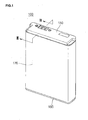
FIG. 1 is a perspective view illustrating an external appearance of a battery pack according to an embodiment of the present invention; -
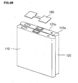
FIG. 2 is an exploded perspective view illustrating the battery pack inFIG. 1 ; -
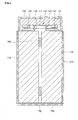
FIG. 3 is a sectional view of the battery pack taken along the line III-III inFIG. 1 ; -
FIG. 4 is a perspective view illustrating a connector tab employed in the battery pack according to the embodiment of the present invention; -
FIGS. 5A to 5H are perspective views illustrating an assembling process of the battery pack according to the embodiment of the present invention; -
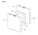
FIG. 6 A is a sectional view illustrating main parts of the battery pack according to the embodiment of the present invention; -
FIG. 6B is a sectional view illustrating a swelling occurring in the battery pack inFIG. 6A ; -
FIG. 7 is a sectional view illustrating main parts of a battery pack according to another embodiment of the present invention; and -
FIG. 8 is a sectional view illustrating main parts of a battery pack according to still another embodiment of the present invention. - Hereinafter, embodiments of the present invention will be described in detail with reference to the accompanying drawings.
- Referring to
FIGS. 1 to 4 , abattery pack 100 according to an embodiment of the present invention includes afirst battery cell 110, asecond battery cell 120 electrically connected to thefirst battery cell 110, a protection circuit module (PCM)assembly 130 electrically connected to thefirst battery cell 110 and thesecond battery cell 120, atop case 150 accommodating thePCM assembly 130 and coupled to tops of the first andsecond battery cells bottom case 160 coupled to the lower sides of the first andsecond battery cells label 170 wrapping lateral sides of the first andsecond battery cells - The
battery pack 100 further includesconnector tabs 140 and 140' electrically connecting thePCM assembly 130 to thefirst battery cell 110 and thesecond battery cell 120. - Each of the
first battery cell 110 and thesecond battery cell 120 has an approximate hexahedron. However, the shapes of the first andsecond battery cells tops second battery cells negative terminals second battery cells lateral sides lateral sides Bottoms second battery cells lateral sides lateral sides - The
first battery cell 110 and thesecond battery cell 120 are bonded to each other in a way that one of the widelateral sides 110b and one of the widelateral sides 120b are facing and are bonded to each other. In this case, a spacer such as aninsulator tape 180 is interposed between the widelateral side 110b of thefirst battery cell 110 and the widelateral side 120b of thesecond battery cell 120. Preferably, theinsulator tape 180 is a double-sided adhesive tape. - The
insulator tape 180 has a through-hole 181 formed in the middle thereof. Preferably, the through-hole 181 has a rectangular shape, but its shape is not limited thereto. A space defined by the through-hole 181 acts as an escaping or release space that is preferably sized so as to accommodate the increased thicknesses of the first andsecond battery cells battery cells - The
PCM assembly 130 includes acircuit board 131, anelectric device 132 installed on thecircuit board 131, and anexternal terminal 133 conducting current from the battery cells to the outside. - The
circuit board 131 has a rectangular shape with a width corresponding to thetops battery cells circuit board 131 has electrode through-holes negative terminal 111 of thefirst battery cell 110 and thenegative terminal 121 of thesecond battery cell 120 are electrically connected to a negative terminal (not shown) of thecircuit board 131. Thecircuit board 131 hascutaway portions 131c formed at four corners. Each of thecutaway portions 131c has an arc shape but the shape is not limited thereto.
Thecutaway portions 131c are formed to enable laser welding of theconnector tabs 140 and 140' to the tops of thebattery cells cutaway portions 131c. Further, the overall configuration of thecircuit board 131 may be selected to permit access to perform the laser welding of theconnector tabs 140, 140'. - The
connector tabs 140 and 140' includeboard connection portions 141 and 141' installed on thecircuit board 131, firstcell connection portions 144 and 144' connected to thefirst battery cell 110, secondcell connection portions 145 and 145' connected to thesecond battery cell 120,first connectors 142 and 142' connecting theboard connection portions 141 and 141' to the firstcell connection portions 144 and 144', andsecond connectors 143 and 143' connecting theboard connection portions 141 and 141' to the secondcell connection portions 145 and 145'. - Thus, the
circuit board 131 is supported by thefirst connector tab 140 and the second connector tab 140' to be placed on thetops first battery cell 110 and thesecond battery cell 120. - Since the structure of the
first connector tab 140 is identical to that of the second connector tab 140', hereinafter thefirst connector tab 140 only will be described in detail. Theboard connection portion 141 is parallel to thecircuit board 131. Thefirst connector 142 and thesecond connector 143 are integrally formed with the lower sides of the lateral edges of theboard connection portion 141. The firstcell connection portion 144 is integrally formed with an edge of thefirst connector 142 and thesecond connection portion 145 is integrally formed with an edge of thesecond connector 143. The first andsecond connection portions board connection portion 141 therebetween. - Thus, the
circuit board 131 is electrically connected to the twobattery cells connector tabs 140 and 140'. In this configuration, thefirst battery cell 110 is connected in parallel to thesecond battery cell 120. - The
first connector tab 140 and the second connector tab 140' electrically connect positive terminals of the first andsecond battery cells 110 and 120 (surfaces of the battery cells) to a positive terminal (not shown) of thecircuit board 131. In this case, at least one of the first andsecond connector tabs 140 and 140' connects the first andsecond battery cells circuit board 131. Preferably, the first andsecond connector tabs 140 and 140' are made of nickel or nickel alloy with good electrical conductivity, but are not limited thereto. Thus, any one of the first andsecond connector tabs 140 and 140', which electrically connects thebattery cells circuit board 131, may be made of the nickel with good electrical conductivity and the other may not be made of an electrical conductor. - The
top case 150 includes acase body 151 and right and leftframes case body 151 has a hexahedron shape with an internal space accommodating thePCM assembly 130, and the right and leftframes case body 151. Thecase body 151 includes a singleplanar surface 151a and fourlateral sides 151b extending from theplanar surface 151a. Theplanar surface 151a has external terminal through-holes 151c formed at a side and a water-sensitive label attachment 151d formed at the other side.Guide ribs 151e to which thelabel 170 is attached extend downwardly from the fourlateral sides 151b. The right and leftframes case body 151 in the vertical direction. The right and leftframes protrusions - The
protrusions frames protrusions lateral sides second battery cells - The
bottom case 160 includes acase body 161 and right and leftframes case body 161 has a rectangular shape with a size sufficient to accommodate the bottoms of the first andsecond battery cells frames case body 161. Thecase body 161 includes a singleplanar surface 161a and bothlateral sides 161b extending from an edge of theplanar surface 161a. Guide ribs 161e to which thelabel 170 is attached extend from thelateral sides 161b. The right and leftframes case body 161 in the vertical direction. The right and leftframes protrusions protrusions frames protrusions lateral sides second battery cells -
Grooves frames top case 150 respectively.Protrusions frames bottom case 160 to be inserted into thegrooves grooves protrusions - The
label 170 is attached to wrap a circumference of an assembly of the first andsecond battery cells top case 150, and thebottom case 160 at least one turn. Thus, the first andsecond battery cells lateral sides insulation tape 180 and are wrapped by thelabel 170. Thelabel 170 is made of insulator and insulates the first andsecond battery cells - An upper end of the
label 170 wraps theguide ribs 151e of thetop case 150 and a lower end of thelabel 170 wraps theguide ribs 161c of thebottom case 160. Thus, thetop case 150 and thebottom case 160 are coupled with the first andsecond battery cells label 170. - The
tops second battery cells second insulator tape 190. Due to thesecond insulator tape 190, the first andsecond battery cells PCM assembly 130. - The
bottoms second battery cells adhesive tape 195. Theadhesive tape 195 securely adheres to thefirst battery cell 110 and thesecond battery cell 120. Moreover, the adhesive tape employs a double-sided tape. Thus, due to theadhesive tape 195, thebottom case 160 can be securely adhered to thebottoms second battery cells - An assembling process of the battery pack according to the embodiment of the present invention will be described.
- 1. Attach the first battery cell and the second battery cell with the insulator tape.
Referring toFIG. 5A , when one widelateral side 110b of thefirst battery cell 110 faces one widelateral side 120b of thesecond battery cell 120, theinsulator tape 180 is interposed therebetween and the first andsecond battery cells second battery cells insulator tape 180. Theinsulator tape 180 has the through-hole 181. The through-hole 181 corresponds to an approximate middle portion where the battery cells swell during the charge of the battery cells. In general, when a battery cell is charged approximately 500 times, a thickness increases by about 10% of the initial thickness. Even a battery cell repeatedly charged several times can escape through the through-hole of theinsulator tape 180 as much as the increased thickness. Thus, thefirst battery cell 110 and thesecond battery cell 120 are less likely to push each other while maintaining the assembled state. - 2. Adhere the second insulator tape to the tops of the first and second battery cells.
Referring toFIG. 5B , thesecond insulator tape 190 is adhered to the tops 110a and 120a of the first andsecond battery cells
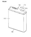
Thetops second battery cells second insulator tape 190 inhibits shorting with other elements. - 3. Place the PCM assembly on the tops of the first and second battery cells to be welded.
Referring toFIG. 5C , thePCM assembly 130 is welded to thefirst connector tab 140 and the second connector tab 140'. Firstly, theboard connection portions 141 and 141' of theconnector tabs 140 and 140' are welded to the bottom of thecircuit board 131. And, the first and secondcell connection portions connector tabs 140 and 140' are placed on the tops 110a and 120a of the first andsecond battery cells
ThePCM assembly 130 is welded to the battery cells such that the first and secondcell connection portions first connector tab 140 and the first and second cell connection portions 144' and 145' of the second connector tab 140' are welded to the tops 110a and 120a of the first andsecond battery cells cell connection portions first connector tab 140 and the first and second cell connection portions 144' and 145' of the second connector tab 140' are exposed through thecutaway portions 131c formed at the four corners of thecircuit board 131 so that the laser welding can be carried out.
Cases of the first andsecond battery cells second connector tabs 140 and 140' may be made of nickel (Ni). Aluminum and nickel allow excellent laser welding. - 4. Adhere the adhesive tape to the bottoms of the first and second battery cells.
Referring toFIG. 5D , a singleadhesive tape 195 is adhered to thebottoms second battery cells second battery cells - 5. Couple the bottom case.
Referring toFIG. 5E , thebottom case 160 is coupled with the lower sides of the first andsecond battery cells case body 161 of thebottom case 160 supports thebottoms second battery cells frames bottom case 160 support the narrowlateral sides second battery cells protrusions frames lateral sides second battery cells protrusions second battery cells case body 161.
Thebottom case 160 maintains adhesion to the first andsecond battery cells adhesive tape 195 adhered to thebottoms second battery cells - 6. Couple the top case.
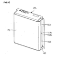
Referring toFIG. 5F , thetop case 150 is coupled with the tops of the first andsecond battery cells PCM assembly 130 is placed.
Thecase body 151 of thetop case 150 is placed on the top of thePCM assembly 130. The right and leftframes top case 150 support the narrowlateral sides second battery cells Protrusions frames lateral sides second battery cells case body 151.
Thetop case 150 is coupled with thebottom case 160. Theprotrusions frames bottom case 160 are inserted into thegrooves frames top case 150, so that male-female coupling is established. - 7. Attach the label.
Referring toFIG. 5G , thelabel 170 fully wraps the circumference of the first andsecond battery cells frames top case 150 and thebottom case 160 fill up the gaps G between the first andsecond battery cells label 170 is wrapped, the right and leftframes top case 150 and thebottom case 160 support thelabel 170.
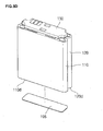
An upper end of thelabel 170 is attached to theguide ribs 151e of thetop case 150 to fix thetop case 150 to the first andsecond battery cells 110. A lower end of thelabel 170 is attached to theguide ribs 161c of thebottom case 160 to fix thebottom case 160 to the first andsecond battery cells - 8. Attach the water-sensitive label.
- Referring to
FIG. 5H , the water-sensitive label 175 is attached to the water-sensitive label attachment 151d formed on the top of thetop case 150. In this implementation, thelabel 175 is a water sensitive label that turns color when the battery is exposed to water. In this way, the cause of failure of the device using the battery can be determined, e.g., the label can tell if an electronic device, such as a mobile phone, has been immersed in water. - As described above, in the assembled battery pack according to the embodiment of the present invention, the two battery cells are controlled by the single PCM assembly during the charge and discharge so that inferior performance caused by overcharge and overdischarge is reduced.
- The first and
second battery cells PCM assembly 130 such that thenegative terminals battery cells circuit board 131. The first andsecond battery cells circuit board 131 by the first andsecond connector tabs 140 and 140'. - On the tops of the first and
second battery cells connector tabs 140 and 140' support thePCM assembly 130. Theconnector tabs 140 and 140' respectively have a bridge shape in which theboard connection portions 141 and 141', the first andsecond connection portions cell connection portions 144 and 144', and the secondcell connection portions 145 and 145' are integrally formed with each other. - Although the
connector tabs 140 and 140' of thebattery pack 100 according to the embodiment of the present invention respectively are configured such that vertical relationships between theboard connection portions 141 and 141', and the first andsecond connection portions cell connection portions - A battery pack according to another embodiment of the present invention will be described.
-
FIGS. 6A and6B , abattery pack 200 according to another embodiment of the present invention includes afirst battery cell 110 and asecond battery cell 120 electrically connected to thefirst battery cell 110, a protection circuit module (PCM)assembly 130 electrically connected to the first andsecond battery cells top case 150 accommodating thePCM assembly 130 and coupled to tops of the first andsecond battery cells bottom case 160 coupled to the lower sides of the first andsecond battery cells label 170 wrapping lateral sides of the first andsecond battery cells battery pack 100 according to the embodiment of the present invention. The same reference numerals are assigned to the same elements and their description will be omitted. - The
battery pack 200 according to another embodiment of the present invention includes a connector tab, different from that of thebattery pack 100 according to the previous embodiment of the present invention, electrically connecting the first andsecond battery cells PCM assembly 130. The connector tab includes first and second connector tabs supporting both ends of thePCM assembly 130. Since the first and second connector tabs are identical to each other, asingle connector tab 240 only will be described. - The
connector tab 240 in another embodiment of the present invention includes aboard connection portion 241 installed in thePCM assembly 130, a firstcell connection portion 244 connected to thefirst battery cell 110, a secondcell connection portion 245 connected to thesecond battery cell 120, afirst connection portion 242 connecting theboard connection portion 241 to the firstcell connection portion 244, and asecond connection portion 243 connecting theboard connection portion 241 to the secondcell connection portion 245. - The
board connection portion 241 is parallel to thePCM assembly 130. The first andsecond connection portions board connection portion 241 in the vertical direction to theboard connection portion 241. - The first
cell connection portion 244 is integrally formed with an edge of thefirst connection portion 242 or aslope portion 246 as described below, and the secondcell connection portion 245 is integrally formed with an edge of thesecond connection portion 243 or aslope portion 247 as described below. The first and secondcell connection portions second connection portions board connection portion 241. - In another embodiment of the present invention, a
slope portion 246 is formed between thefirst connection portion 242 and the firstcell connection portion 244 and aslope portion 247 is formed between thesecond connection portion 243 and the secondcell connection portion 245. Theslope portions second connection portions cell connection portions - Operation of the battery pack according to another embodiment of the present invention will be described.
- In the
battery pack 200 according to another embodiment of the present invention, when the first andsecond battery cells second battery cells FIG. 6B , are spaced away from each other with respect to theinsulator tape 180. - In this case, the
connector tab 240 is deformed such that the first andsecond connection portions board connection portion 241 by theslopes - The
connection portions connector tab 240 moved away from each other as the gap, between the battery cells, increases due to the swelling of the first andsecond battery cells cell connection portions connector tab 240 are less likely to be separated from the tops 110a and the 120a of the first andsecond battery cells - When the angle θ of the
slopes connection portions slopes connection portions cell connection portions second battery cells slopes cell connection portions slopes connection portions cell connection portions second battery cells - A
battery pack 300 according to still another embodiment of the present invention will described as follows. - Referring to
FIG. 7 , since thebattery pack 300 according to still another embodiment of the present invention is established by a connector tab, thebattery pack 300 will be described by concentrating on the connector tab. - A
connector tab 340 in thebattery pack 300 according to still another embodiment of the present invention includes aboard connection portion 341 installed in thePCM assembly 130, a firstcell connection portion 344 electrically connected to thefirst battery cell 110, a secondcell connection portion 345 electrically connected to thesecond battery cell 120, afirst connection portion 342 electrically connecting theboard connection portion 341 to the firstcell connection portion 344, and asecond connection portion 343 electrically connecting theboard connection portion 341 to the secondcell connection portion 345. - The
board connection portion 341 is parallel to thePCM assembly 130. The first andsecond connection portions board connection portion 341. - The first
cell connection portion 344 is integrally formed with an edge of thefirst connection portion 342, and the secondcell connection portion 345 is integrally formed with an edge of thesecond connection portion 343. The first and secondcell connection portions second connection portions board connection portion 341, respectively. - In the
connector tab 340 of thebattery pack 300 according to still another embodiment of the present invention, the first andsecond connection portions board connection portion 341 outwardly oblique to the vertical direction. In other words, theconnector tab 240 of thebattery pack 200 according to another embodiment of the present invention is configured such that theslopes second connection portions second connection portions - The first and
second connection portions board connection portion 341 toward the first and secondcell connection portions connection portions - Operation of the
battery pack 300 according to still another embodiment of the present invention will be described. - In this embodiment, when the first and
second battery cells connector tab 340 spreads laterally with respect to theboard connection portion 341. - Thus, the first and
second connection portions connector tab 340 are moved away from each other as the gap increases due to the swelling of the first andsecond battery cells cell connection portions connector tab 340 are less likely to be separated from the tops 110a and 120a of the first andsecond battery cells - A
battery pack 400 according to still another embodiment of the present invention will be described. - Referring to
FIG. 8 , since thebattery pack 400 according to still another embodiment of the present invention is established by a connector tab, thebattery pack 400 will be described by concentrating on the connector tab. - A
connector tab 440 in thebattery pack 400 according to still another embodiment of the present invention includes aboard connection portion 441 installed in thePCM assembly 130, a firstcell connection portion 444 electrically connected to thefirst battery cell 110, a secondcell connection portion 445 electrically connected to thesecond battery cell 120, afirst connection portion 442 electrically connecting theboard connection portion 441 to the firstcell connection portion 444, and asecond connection portion 443 electrically connecting theboard connection portion 441 to the secondcell connection portion 445. - The
board connection portion 441 is parallel to thePCM assembly 130. The first andsecond connection portions board connection portion 441. - The first
cell connection portion 444 is integrally formed with an edge of thefirst connection portion 442, and the secondcell connection portion 445 is integrally formed with an edge of thesecond connection portion 443. The first and secondcell connection portions second connection portions board connection portion 441, respectively. - The first and
second connection portions connector tab 440 are rounded. - The first and
second connection portions board connection portion 441 opposite to the positions where the first and secondcell connection portions cell connection portions - Even in the
battery pack 400 employing theconnector tab 400, when the first andsecond battery cells second connection portions connector tab 400 spread in the lateral direction. - Thus, the first and
second connection portions connector tab 440 are moved apart from each other as the gap increase due to the swelling of the first andsecond battery cells cell connection portions connector tab 440 are less likely to be separated from the tops 110a and 120a of the first andsecond battery cells
Claims (18)
- A battery assembly comprising:a first battery cell (110);a second battery cell (120), wherein the first and second battery cells are mounted adjacent to each other;a protection circuit module (130) that is electrically coupled to the first and second battery cells; andat least one connector tab (140, 140', 240, 340, 440) that extends across adjacent surfaces (110a, 120a) of the first and second battery cells to electrically connect the first and second battery cells to one another, the at least one connector tab including a protection circuit mounting portion (141, 141', 241, 341, 441) and first and second battery cell mounting portions (144, 145; 144', 145', 244, 245, 344, 345, 444, 445) on either side of the protection circuit mounting portion, wherein the protection circuit module is coupled to the protection circuit mounting portion and the first and second battery cells are coupled to the first and second battery cell mounting portions;wherein the protection circuit mounting portion is raised relative to the first and second battery cell mounting portions.
- The assembly of claim 1, further comprising a case that defines an inner recess wherein the first battery cell, the second battery cell, the protection circuit module and the at least one connector tab are positioned in the inner recess.
- The assembly of claim 1 or 2, wherein the protection circuit module is shaped in the regions adjacent the protection circuit mounting portion of the at least one connector tab so as to at least partially expose the battery cell mounting portions of the at least one connector tab to thereby permit laser welding of the battery cell mounting portions to the battery cells.
- The assembly of claim 3, wherein the protection circuit module is generally rectangular in shape having a first and a second end and the at least one connector tab is mounted adjacent to a first end of the protection circuit module and wherein the corners of the first end of the protection circuit module are cut-away so as to at least partially expose the battery cell mounting portions of the at least one connector tab.
- The assembly of any one of the preceding claims, wherein the first and second battery cells each have two elongate sides and two ends and wherein the first and second battery cells are positioned so that elongate sides of the first and second battery cells are positioned proximate to each other.
- The assembly of claim 5, further comprising a spacer (180) interposed between the first and second battery cells, wherein the spacer includes an opening (181) that is positioned with respect to the first and second battery cells so as to allow the walls of the first and second battery cells to extend into the opening when swelling to thereby reduce the likelihood that the first and second battery cells will exert pressure against each other due to swelling.
- The assembly of any one of the preceding claims, wherein the at least one connector tab comprises a first and a second connector tab (140, 140') wherein at least one of the first and second connector tabs is formed of a conductive material so as to electrically connect the first and second battery cells to the protection circuit module.
- The assembly of claim 7, wherein the first and second connector tabs each comprise the protection circuit module mounting portion (141, 141') having first and second outer ends and the first and second battery cell mounting portions (144, 145; 144', 145') and first and second interconnecting portions (142, 143; 142', 143', 242, 243, 342, 343, 442, 443) respectively interconnecting the first outer end of the protection circuit module mounting portion to the first battery cell mounting portion and the second outer end of the protection circuit module mounting portion to the second battery cell mounting portion.
- The assembly of claim 8, wherein the protection circuit mounting portion is coupled to the battery cell mounting portions by the interconnecting portions which are sufficiently flexible so as to permit lateral movement of the battery cell mounting portion relative to the protection circuit mounting portion due to swelling of the battery cells.
- The assembly of claim 9, wherein the inner end of the first battery cell mounting portion and the inner end of the second battery cell mounting portion are respectively substantially aligned with the first and second outer ends of the protection circuit module mounting portion.
- The assembly of claim 8, 9 or 10, wherein the first and second interconnecting portions (142, 143) are substantially straight extending between the first and second outer ends of the protection circuit module mounting portion and the inner ends of the first and second battery cell mounting portions.
- The assembly of claim 8, 9 or 10, wherein the first and second interconnecting portions (442, 443) are bent so as to extend inward so that disengagement of the first and second battery cells from the first and second connector tabs as a result of movement of the first and second battery cells due to swelling of the battery cells is inhibited.
- The assembly of claim 8 or 9, wherein the first and second interconnecting portions (242, 243, 246, 247, 342, 343) are at least partially sloped so that the inner ends of the first and second battery cell mounting portions are located outward of the first and second outer ends of the protection circuit module mounting portion so that disengagement of the first and second battery cells from the first and second connector tabs as a result of movement of the first and second battery cells due to swelling of the battery cells is inhibited.
- The assembly of claim 13, wherein the first and second interconnecting portions are substantially straight (342, 343) extending at an angle θ to the first direction.
- The assembly of claim 14, wherein the angle θ is between approximately 20 degrees and 70 degrees to the first direction.
- The assembly of claim 13, wherein the first and second interconnecting portions include a first substantially straight section (242, 243) and a second angled section (246, 247) wherein the second angled section extends at an angle θ to the first direction.
- The assembly of claim 16, wherein the substantially straight sections of the first and second interconnecting portions are respectively coupled to the first and second outer ends of the protection circuit module mounting portion and the angled section extends outward from the substantially straight sections at an angle θ which is between approximately 20 to 70 degrees from the first direction.
- The assembly of claim 2, wherein the case is comprised of a top case, a bottom case and a label, wherein the top case engages with the bottom case with the first and second battery cells and the protection circuit module interposed therebetween and wherein the label is wrapped around the first and second battery cells and extends between the top and bottom case to thereby enclose the first and second battery cells and the protection circuit module.
Applications Claiming Priority (2)
| Application Number | Priority Date | Filing Date | Title |
|---|---|---|---|
| US7454908P | 2008-06-20 | 2008-06-20 | |
| US12/356,247 US8999536B2 (en) | 2008-06-20 | 2009-01-20 | Battery pack |
Publications (3)
| Publication Number | Publication Date |
|---|---|
| EP2136451A2 EP2136451A2 (en) | 2009-12-23 |
| EP2136451A3 EP2136451A3 (en) | 2013-03-27 |
| EP2136451B1 true EP2136451B1 (en) | 2014-04-30 |
Family
ID=40939057
Family Applications (1)
| Application Number | Title | Priority Date | Filing Date |
|---|---|---|---|
| EP09162879.2A Active EP2136451B1 (en) | 2008-06-20 | 2009-06-16 | Battery pack |
Country Status (5)
| Country | Link |
|---|---|
| US (1) | US8999536B2 (en) |
| EP (1) | EP2136451B1 (en) |
| JP (1) | JP5191957B2 (en) |
| KR (1) | KR101094037B1 (en) |
| CN (1) | CN101609902B (en) |
Families Citing this family (35)
| Publication number | Priority date | Publication date | Assignee | Title |
|---|---|---|---|---|
| KR100876266B1 (en) * | 2007-09-28 | 2008-12-26 | 삼성에스디아이 주식회사 | Rechargeable battery |
| KR101009567B1 (en) * | 2008-12-05 | 2011-01-18 | 삼성에스디아이 주식회사 | Battery Pack |
| KR101122904B1 (en) * | 2009-12-18 | 2012-03-20 | 삼성에스디아이 주식회사 | Battery pack |
| JP2013200940A (en) * | 2010-06-14 | 2013-10-03 | Toyota Motor Corp | Power storage device |
| KR101199108B1 (en) * | 2010-07-12 | 2012-11-09 | 삼성에스디아이 주식회사 | case of secondary battery and secondary battery thereof |
| KR101152443B1 (en) | 2010-07-12 | 2012-06-01 | 삼성에스디아이 주식회사 | Battery Pack |
| US8343651B2 (en) * | 2010-07-16 | 2013-01-01 | Samsung Sdi Co., Ltd. | Battery pack |
| US9065085B2 (en) | 2011-04-19 | 2015-06-23 | Samsung Sdi Co., Ltd. | Battery pack |
| US9017836B2 (en) | 2011-07-06 | 2015-04-28 | Samsung Sdi Co., Ltd. | Battery pack |
| JP5966591B2 (en) | 2012-05-15 | 2016-08-10 | ソニー株式会社 | Battery pack |
| KR101908587B1 (en) * | 2012-06-12 | 2018-10-17 | 에스케이이노베이션 주식회사 | Easy assembling Secondary battery module |
| JP5915403B2 (en) * | 2012-06-18 | 2016-05-11 | 株式会社Gsユアサ | Assembled battery |
| KR101908452B1 (en) * | 2012-06-28 | 2018-10-17 | 에스케이이노베이션 주식회사 | Easy assembling all-in-one secondary battery module |
| KR102028168B1 (en) * | 2012-08-20 | 2019-10-02 | 삼성에스디아이 주식회사 | Battery pack having external member |
| KR101397028B1 (en) * | 2012-09-13 | 2014-05-20 | 삼성에스디아이 주식회사 | Battery pack |
| KR102052588B1 (en) * | 2013-08-13 | 2019-12-05 | 삼성에스디아이 주식회사 | Rechargeable battery pack |
| KR102222888B1 (en) * | 2014-04-09 | 2021-03-04 | 삼성에스디아이 주식회사 | Battery module |
| USD762566S1 (en) * | 2014-09-08 | 2016-08-02 | Parrot Drones | Battery for a headphone |
| USD764401S1 (en) * | 2014-09-08 | 2016-08-23 | Parrot Drone | Battery for a remote-controlled toy |
| KR102263200B1 (en) | 2015-01-19 | 2021-06-10 | 삼성에스디아이 주식회사 | Battery Pack |
| KR102324344B1 (en) * | 2015-01-27 | 2021-11-10 | 삼성에스디아이 주식회사 | Battery Pack |
| USD780112S1 (en) * | 2015-02-18 | 2017-02-28 | Limefuel, LLC | Rechargeable battery device |
| USD788698S1 (en) * | 2015-02-18 | 2017-06-06 | Limefuel, LLC | Rechargeable battery device |
| USD815032S1 (en) * | 2015-02-20 | 2018-04-10 | Limefuel, LLC | Rechargeable battery device |
| US10164296B2 (en) * | 2015-03-12 | 2018-12-25 | Johnson Controls Technology Company | Battery module separator plates |
| JP6585726B2 (en) * | 2015-10-02 | 2019-10-02 | 日立オートモティブシステムズ株式会社 | Assembled battery |
| CN106972144B (en) * | 2016-01-14 | 2023-03-17 | 宁德时代新能源科技股份有限公司 | Secondary battery |
| JP6418257B2 (en) * | 2017-01-25 | 2018-11-07 | ソニー株式会社 | Battery pack |
| KR102422515B1 (en) * | 2017-10-19 | 2022-07-19 | 삼성에스디아이 주식회사 | Battery pack |
| CN109510255B (en) * | 2018-10-31 | 2021-08-27 | 深圳欣旺达智能科技有限公司 | Double-battery quick-charging structure and mobile terminal |
| KR20200053981A (en) * | 2018-11-09 | 2020-05-19 | 주식회사 아모그린텍 | Apparatus for detecting the pressure of battery |
| JP2021061152A (en) * | 2019-10-07 | 2021-04-15 | シャープ株式会社 | Battery pack and electronic apparatus |
| US11832428B2 (en) | 2021-07-19 | 2023-11-28 | Google Llc | Battery with electromagnetic interference shielding |
| CN113451630A (en) * | 2021-07-27 | 2021-09-28 | 孟琳 | Stack packaging method and device of flow battery system |
| WO2023097501A1 (en) * | 2021-11-30 | 2023-06-08 | 宁德时代新能源科技股份有限公司 | Battery, method and device for manufacturing same, and electrical device |
Family Cites Families (23)
| Publication number | Priority date | Publication date | Assignee | Title |
|---|---|---|---|---|
| EP0607675B1 (en) * | 1992-12-22 | 1996-09-25 | Honda Giken Kogyo Kabushiki Kaisha | Battery with rust preventive structure |
| JP4406940B2 (en) | 1998-02-24 | 2010-02-03 | ソニー株式会社 | Single cell electrical connection device |
| GB9900396D0 (en) | 1999-01-08 | 1999-02-24 | Danionics As | Arrangements of electrochemical cells |
| KR100322102B1 (en) | 1999-12-14 | 2002-02-06 | 김순택 | Connector of Battery with PCM |
| JP3614767B2 (en) | 2000-10-20 | 2005-01-26 | 松下電器産業株式会社 | Method for forming exterior body of electrical product |
| JP3877623B2 (en) | 2002-03-28 | 2007-02-07 | 三洋電機株式会社 | Pack battery manufacturing method |
| KR100958647B1 (en) | 2002-12-18 | 2010-05-20 | 삼성에스디아이 주식회사 | Pouch type secondary battery |
| JP3806696B2 (en) | 2003-02-14 | 2006-08-09 | 三洋電機株式会社 | Pack battery |
| JP4301929B2 (en) * | 2003-12-10 | 2009-07-22 | 三洋電機株式会社 | Battery pack |
| BRPI0507558B8 (en) * | 2004-02-13 | 2023-01-10 | Lg Chemical Ltd | BATTERY PACK |
| WO2005078021A1 (en) | 2004-02-18 | 2005-08-25 | Kawamura Institute Of Chemical Research | Organic-inorganic composite nanofiber, organic-inorganic composite structure and method for producing those |
| JP4480456B2 (en) | 2004-05-12 | 2010-06-16 | 埼玉日本電気株式会社 | Battery pack and portable communication terminal using the same |
| JP2006040775A (en) | 2004-07-29 | 2006-02-09 | Tocad Energy Co Ltd | Combination structure of battery |
| KR100601514B1 (en) | 2004-09-24 | 2006-07-19 | 삼성에스디아이 주식회사 | Conductive plate structure of battery pack |
| JP4716719B2 (en) | 2004-12-03 | 2011-07-06 | 三洋電機株式会社 | Battery pack |
| TWI328892B (en) * | 2005-08-12 | 2010-08-11 | Sony Corp | Secondary battery |
| JP5011678B2 (en) * | 2005-08-12 | 2012-08-29 | ソニー株式会社 | Secondary battery |
| JP5054905B2 (en) | 2005-09-05 | 2012-10-24 | 株式会社オートネットワーク技術研究所 | Connecting the battery output terminal to the terminal fitting |
| KR100850866B1 (en) | 2005-12-27 | 2008-08-07 | 주식회사 엘지화학 | Frame Member for Preparation of Battery Pack |
| KR100719723B1 (en) | 2005-12-29 | 2007-05-17 | 삼성에스디아이 주식회사 | Coductory plate and pack secondary battery using it |
| KR20070108755A (en) | 2006-05-08 | 2007-11-13 | 삼성에스디아이 주식회사 | Battery pack |
| KR100873308B1 (en) | 2006-06-05 | 2008-12-12 | 주식회사 엘지화학 | High Capacity Battery Cell Employed with Two or More Unit Cells |
| KR100984133B1 (en) * | 2008-04-11 | 2010-09-28 | 삼성에스디아이 주식회사 | Battery pack |
-
2009
- 2009-01-20 US US12/356,247 patent/US8999536B2/en active Active
- 2009-03-10 KR KR1020090020215A patent/KR101094037B1/en active IP Right Grant
- 2009-06-16 EP EP09162879.2A patent/EP2136451B1/en active Active
- 2009-06-18 JP JP2009145601A patent/JP5191957B2/en active Active
- 2009-06-18 CN CN2009101424857A patent/CN101609902B/en active Active
Also Published As
| Publication number | Publication date |
|---|---|
| EP2136451A3 (en) | 2013-03-27 |
| US20090317703A1 (en) | 2009-12-24 |
| EP2136451A2 (en) | 2009-12-23 |
| JP5191957B2 (en) | 2013-05-08 |
| KR101094037B1 (en) | 2011-12-19 |
| CN101609902B (en) | 2012-02-22 |
| JP2010003691A (en) | 2010-01-07 |
| US8999536B2 (en) | 2015-04-07 |
| CN101609902A (en) | 2009-12-23 |
| KR20090132490A (en) | 2009-12-30 |
Similar Documents
| Publication | Publication Date | Title |
|---|---|---|
| EP2136451B1 (en) | Battery pack | |
| US7611797B2 (en) | Lithium secondary battery with safety device | |
| EP2453500B1 (en) | A rechargeable battery, method of assembling a rechargeably battery, and a rechargeable battery module | |
| KR101059756B1 (en) | New rechargeable battery pack | |
| KR100870349B1 (en) | Terminal of ProtectCircuit Module and Secondary Battery of using the same | |
| CN102376931B (en) | Rechargeable battery, battery module and electrode terminal assembly of rechargeable battery | |
| JP4749130B2 (en) | Secondary battery and method for forming the same | |
| KR101009567B1 (en) | Battery Pack | |
| KR101001315B1 (en) | Secondary Battery Pack Having Excellent Energy Density and PCM Assembly therefor | |
| JP4187685B2 (en) | Secondary battery | |
| JP4499648B2 (en) | Lithium ion secondary battery | |
| EP2302718B1 (en) | Secondary battery | |
| KR101441524B1 (en) | Secondary Battery of Novel Structure | |
| US8481183B2 (en) | Secondary battery | |
| WO2021023060A1 (en) | Secondary battery and battery pack | |
| KR101198026B1 (en) | Secondary Battery Pack of Novel Structure | |
| EP2328200B1 (en) | Battery assembly | |
| US8216706B2 (en) | Battery pack | |
| KR101432224B1 (en) | Secondary Battery Pack of Embedded Type of Novel Structure | |
| EP2273585B1 (en) | Battery pack | |
| KR101057578B1 (en) | Polymer battery pack | |
| KR101057525B1 (en) | Battery pack | |
| KR101130048B1 (en) | Secondary Battery Pack Having PCM Assembly of Novel Structure | |
| CN218975498U (en) | Battery and electronic equipment | |
| US8741452B2 (en) | Secondary battery |
Legal Events
| Date | Code | Title | Description |
|---|---|---|---|
| PUAI | Public reference made under article 153(3) epc to a published international application that has entered the european phase |
Free format text: ORIGINAL CODE: 0009012 |
|
| 17P | Request for examination filed |
Effective date: 20090616 |
|
| AK | Designated contracting states |
Kind code of ref document: A2 Designated state(s): AT BE BG CH CY CZ DE DK EE ES FI FR GB GR HR HU IE IS IT LI LT LU LV MC MK MT NL NO PL PT RO SE SI SK TR |
|
| PUAL | Search report despatched |
Free format text: ORIGINAL CODE: 0009013 |
|
| AK | Designated contracting states |
Kind code of ref document: A3 Designated state(s): AT BE BG CH CY CZ DE DK EE ES FI FR GB GR HR HU IE IS IT LI LT LU LV MC MK MT NL NO PL PT RO SE SI SK TR |
|
| RIC1 | Information provided on ipc code assigned before grant |
Ipc: H02J 7/00 20060101AFI20130221BHEP Ipc: H01M 2/20 20060101ALI20130221BHEP Ipc: H01M 10/42 20060101ALI20130221BHEP |
|
| GRAP | Despatch of communication of intention to grant a patent |
Free format text: ORIGINAL CODE: EPIDOSNIGR1 |
|
| INTG | Intention to grant announced |
Effective date: 20140122 |
|
| GRAS | Grant fee paid |
Free format text: ORIGINAL CODE: EPIDOSNIGR3 |
|
| GRAA | (expected) grant |
Free format text: ORIGINAL CODE: 0009210 |
|
| AK | Designated contracting states |
Kind code of ref document: B1 Designated state(s): AT BE BG CH CY CZ DE DK EE ES FI FR GB GR HR HU IE IS IT LI LT LU LV MC MK MT NL NO PL PT RO SE SI SK TR |
|
| REG | Reference to a national code |
Ref country code: GB Ref legal event code: FG4D Ref country code: CH Ref legal event code: EP |
|
| RAP2 | Party data changed (patent owner data changed or rights of a patent transferred) |
Owner name: SAMSUNG SDI CO., LTD. |
|
| REG | Reference to a national code |
Ref country code: AT Ref legal event code: REF Ref document number: 665679 Country of ref document: AT Kind code of ref document: T Effective date: 20140515 |
|
| REG | Reference to a national code |
Ref country code: IE Ref legal event code: FG4D |
|
| REG | Reference to a national code |
Ref country code: DE Ref legal event code: R096 Ref document number: 602009023632 Country of ref document: DE Effective date: 20140612 |
|
| REG | Reference to a national code |
Ref country code: AT Ref legal event code: MK05 Ref document number: 665679 Country of ref document: AT Kind code of ref document: T Effective date: 20140430 |
|
| REG | Reference to a national code |
Ref country code: LT Ref legal event code: MG4D |
|
| REG | Reference to a national code |
Ref country code: NL Ref legal event code: VDEP Effective date: 20140430 |
|
| PG25 | Lapsed in a contracting state [announced via postgrant information from national office to epo] |
Ref country code: NL Free format text: LAPSE BECAUSE OF FAILURE TO SUBMIT A TRANSLATION OF THE DESCRIPTION OR TO PAY THE FEE WITHIN THE PRESCRIBED TIME-LIMIT Effective date: 20140430 Ref country code: CY Free format text: LAPSE BECAUSE OF FAILURE TO SUBMIT A TRANSLATION OF THE DESCRIPTION OR TO PAY THE FEE WITHIN THE PRESCRIBED TIME-LIMIT Effective date: 20140430 Ref country code: FI Free format text: LAPSE BECAUSE OF FAILURE TO SUBMIT A TRANSLATION OF THE DESCRIPTION OR TO PAY THE FEE WITHIN THE PRESCRIBED TIME-LIMIT Effective date: 20140430 Ref country code: BG Free format text: LAPSE BECAUSE OF FAILURE TO SUBMIT A TRANSLATION OF THE DESCRIPTION OR TO PAY THE FEE WITHIN THE PRESCRIBED TIME-LIMIT Effective date: 20140730 Ref country code: IS Free format text: LAPSE BECAUSE OF FAILURE TO SUBMIT A TRANSLATION OF THE DESCRIPTION OR TO PAY THE FEE WITHIN THE PRESCRIBED TIME-LIMIT Effective date: 20140830 Ref country code: GR Free format text: LAPSE BECAUSE OF FAILURE TO SUBMIT A TRANSLATION OF THE DESCRIPTION OR TO PAY THE FEE WITHIN THE PRESCRIBED TIME-LIMIT Effective date: 20140731 Ref country code: NO Free format text: LAPSE BECAUSE OF FAILURE TO SUBMIT A TRANSLATION OF THE DESCRIPTION OR TO PAY THE FEE WITHIN THE PRESCRIBED TIME-LIMIT Effective date: 20140730 Ref country code: LT Free format text: LAPSE BECAUSE OF FAILURE TO SUBMIT A TRANSLATION OF THE DESCRIPTION OR TO PAY THE FEE WITHIN THE PRESCRIBED TIME-LIMIT Effective date: 20140430 |
|
| PG25 | Lapsed in a contracting state [announced via postgrant information from national office to epo] |
Ref country code: HR Free format text: LAPSE BECAUSE OF FAILURE TO SUBMIT A TRANSLATION OF THE DESCRIPTION OR TO PAY THE FEE WITHIN THE PRESCRIBED TIME-LIMIT Effective date: 20140430 Ref country code: PL Free format text: LAPSE BECAUSE OF FAILURE TO SUBMIT A TRANSLATION OF THE DESCRIPTION OR TO PAY THE FEE WITHIN THE PRESCRIBED TIME-LIMIT Effective date: 20140430 Ref country code: SE Free format text: LAPSE BECAUSE OF FAILURE TO SUBMIT A TRANSLATION OF THE DESCRIPTION OR TO PAY THE FEE WITHIN THE PRESCRIBED TIME-LIMIT Effective date: 20140430 Ref country code: LV Free format text: LAPSE BECAUSE OF FAILURE TO SUBMIT A TRANSLATION OF THE DESCRIPTION OR TO PAY THE FEE WITHIN THE PRESCRIBED TIME-LIMIT Effective date: 20140430 Ref country code: ES Free format text: LAPSE BECAUSE OF FAILURE TO SUBMIT A TRANSLATION OF THE DESCRIPTION OR TO PAY THE FEE WITHIN THE PRESCRIBED TIME-LIMIT Effective date: 20140430 Ref country code: AT Free format text: LAPSE BECAUSE OF FAILURE TO SUBMIT A TRANSLATION OF THE DESCRIPTION OR TO PAY THE FEE WITHIN THE PRESCRIBED TIME-LIMIT Effective date: 20140430 |
|
| PG25 | Lapsed in a contracting state [announced via postgrant information from national office to epo] |
Ref country code: PT Free format text: LAPSE BECAUSE OF FAILURE TO SUBMIT A TRANSLATION OF THE DESCRIPTION OR TO PAY THE FEE WITHIN THE PRESCRIBED TIME-LIMIT Effective date: 20140901 |
|
| PG25 | Lapsed in a contracting state [announced via postgrant information from national office to epo] |
Ref country code: EE Free format text: LAPSE BECAUSE OF FAILURE TO SUBMIT A TRANSLATION OF THE DESCRIPTION OR TO PAY THE FEE WITHIN THE PRESCRIBED TIME-LIMIT Effective date: 20140430 Ref country code: DK Free format text: LAPSE BECAUSE OF FAILURE TO SUBMIT A TRANSLATION OF THE DESCRIPTION OR TO PAY THE FEE WITHIN THE PRESCRIBED TIME-LIMIT Effective date: 20140430 Ref country code: LU Free format text: LAPSE BECAUSE OF FAILURE TO SUBMIT A TRANSLATION OF THE DESCRIPTION OR TO PAY THE FEE WITHIN THE PRESCRIBED TIME-LIMIT Effective date: 20140616 Ref country code: CZ Free format text: LAPSE BECAUSE OF FAILURE TO SUBMIT A TRANSLATION OF THE DESCRIPTION OR TO PAY THE FEE WITHIN THE PRESCRIBED TIME-LIMIT Effective date: 20140430 Ref country code: SK Free format text: LAPSE BECAUSE OF FAILURE TO SUBMIT A TRANSLATION OF THE DESCRIPTION OR TO PAY THE FEE WITHIN THE PRESCRIBED TIME-LIMIT Effective date: 20140430 Ref country code: MC Free format text: LAPSE BECAUSE OF FAILURE TO SUBMIT A TRANSLATION OF THE DESCRIPTION OR TO PAY THE FEE WITHIN THE PRESCRIBED TIME-LIMIT Effective date: 20140430 Ref country code: RO Free format text: LAPSE BECAUSE OF FAILURE TO SUBMIT A TRANSLATION OF THE DESCRIPTION OR TO PAY THE FEE WITHIN THE PRESCRIBED TIME-LIMIT Effective date: 20140430 Ref country code: BE Free format text: LAPSE BECAUSE OF FAILURE TO SUBMIT A TRANSLATION OF THE DESCRIPTION OR TO PAY THE FEE WITHIN THE PRESCRIBED TIME-LIMIT Effective date: 20140430 |
|
| REG | Reference to a national code |
Ref country code: CH Ref legal event code: PL |
|
| REG | Reference to a national code |
Ref country code: DE Ref legal event code: R097 Ref document number: 602009023632 Country of ref document: DE |
|
| PLBE | No opposition filed within time limit |
Free format text: ORIGINAL CODE: 0009261 |
|
| STAA | Information on the status of an ep patent application or granted ep patent |
Free format text: STATUS: NO OPPOSITION FILED WITHIN TIME LIMIT |
|
| REG | Reference to a national code |
Ref country code: IE Ref legal event code: MM4A |
|
| PG25 | Lapsed in a contracting state [announced via postgrant information from national office to epo] |
Ref country code: IT Free format text: LAPSE BECAUSE OF FAILURE TO SUBMIT A TRANSLATION OF THE DESCRIPTION OR TO PAY THE FEE WITHIN THE PRESCRIBED TIME-LIMIT Effective date: 20140430 |
|
| 26N | No opposition filed |
Effective date: 20150202 |
|
| PG25 | Lapsed in a contracting state [announced via postgrant information from national office to epo] |
Ref country code: CH Free format text: LAPSE BECAUSE OF NON-PAYMENT OF DUE FEES Effective date: 20140630 Ref country code: IE Free format text: LAPSE BECAUSE OF NON-PAYMENT OF DUE FEES Effective date: 20140616 Ref country code: LI Free format text: LAPSE BECAUSE OF NON-PAYMENT OF DUE FEES Effective date: 20140630 |
|
| REG | Reference to a national code |
Ref country code: DE Ref legal event code: R097 Ref document number: 602009023632 Country of ref document: DE Effective date: 20150202 |
|
| PG25 | Lapsed in a contracting state [announced via postgrant information from national office to epo] |
Ref country code: SI Free format text: LAPSE BECAUSE OF FAILURE TO SUBMIT A TRANSLATION OF THE DESCRIPTION OR TO PAY THE FEE WITHIN THE PRESCRIBED TIME-LIMIT Effective date: 20140430 |
|
| PG25 | Lapsed in a contracting state [announced via postgrant information from national office to epo] |
Ref country code: MT Free format text: LAPSE BECAUSE OF FAILURE TO SUBMIT A TRANSLATION OF THE DESCRIPTION OR TO PAY THE FEE WITHIN THE PRESCRIBED TIME-LIMIT Effective date: 20140430 |
|
| REG | Reference to a national code |
Ref country code: FR Ref legal event code: PLFP Year of fee payment: 8 |
|
| PG25 | Lapsed in a contracting state [announced via postgrant information from national office to epo] |
Ref country code: TR Free format text: LAPSE BECAUSE OF FAILURE TO SUBMIT A TRANSLATION OF THE DESCRIPTION OR TO PAY THE FEE WITHIN THE PRESCRIBED TIME-LIMIT Effective date: 20140430 Ref country code: HU Free format text: LAPSE BECAUSE OF FAILURE TO SUBMIT A TRANSLATION OF THE DESCRIPTION OR TO PAY THE FEE WITHIN THE PRESCRIBED TIME-LIMIT; INVALID AB INITIO Effective date: 20090616 |
|
| REG | Reference to a national code |
Ref country code: FR Ref legal event code: PLFP Year of fee payment: 9 |
|
| REG | Reference to a national code |
Ref country code: FR Ref legal event code: PLFP Year of fee payment: 10 |
|
| PG25 | Lapsed in a contracting state [announced via postgrant information from national office to epo] |
Ref country code: MK Free format text: LAPSE BECAUSE OF FAILURE TO SUBMIT A TRANSLATION OF THE DESCRIPTION OR TO PAY THE FEE WITHIN THE PRESCRIBED TIME-LIMIT Effective date: 20140430 |
|
| P01 | Opt-out of the competence of the unified patent court (upc) registered |
Effective date: 20230528 |
|
| PGFP | Annual fee paid to national office [announced via postgrant information from national office to epo] |
Ref country code: FR Payment date: 20230523 Year of fee payment: 15 Ref country code: DE Payment date: 20230524 Year of fee payment: 15 |
|
| PGFP | Annual fee paid to national office [announced via postgrant information from national office to epo] |
Ref country code: GB Payment date: 20230518 Year of fee payment: 15 |