EP2135921A1 - Substance fluorescente m-c-n-o - Google Patents
Substance fluorescente m-c-n-o Download PDFInfo
- Publication number
- EP2135921A1 EP2135921A1 EP08721089A EP08721089A EP2135921A1 EP 2135921 A1 EP2135921 A1 EP 2135921A1 EP 08721089 A EP08721089 A EP 08721089A EP 08721089 A EP08721089 A EP 08721089A EP 2135921 A1 EP2135921 A1 EP 2135921A1
- Authority
- EP
- European Patent Office
- Prior art keywords
- phosphor
- based phosphor
- nitrogen
- carbon
- oxygen
- Prior art date
- Legal status (The legal status is an assumption and is not a legal conclusion. Google has not performed a legal analysis and makes no representation as to the accuracy of the status listed.)
- Granted
Links
- 239000000126 substance Substances 0.000 title description 14
- IJGRMHOSHXDMSA-UHFFFAOYSA-N Atomic nitrogen Chemical compound N#N IJGRMHOSHXDMSA-UHFFFAOYSA-N 0.000 claims abstract description 65
- OKTJSMMVPCPJKN-UHFFFAOYSA-N Carbon Chemical compound [C] OKTJSMMVPCPJKN-UHFFFAOYSA-N 0.000 claims abstract description 47
- 229910052799 carbon Inorganic materials 0.000 claims abstract description 47
- QVGXLLKOCUKJST-UHFFFAOYSA-N atomic oxygen Chemical compound [O] QVGXLLKOCUKJST-UHFFFAOYSA-N 0.000 claims abstract description 36
- 239000001301 oxygen Substances 0.000 claims abstract description 36
- 229910052760 oxygen Inorganic materials 0.000 claims abstract description 36
- 238000000295 emission spectrum Methods 0.000 claims abstract description 34
- 229910052757 nitrogen Inorganic materials 0.000 claims abstract description 32
- OAICVXFJPJFONN-UHFFFAOYSA-N Phosphorus Chemical compound [P] OAICVXFJPJFONN-UHFFFAOYSA-N 0.000 claims description 251
- 238000000034 method Methods 0.000 claims description 69
- 238000010304 firing Methods 0.000 claims description 49
- 239000000203 mixture Substances 0.000 claims description 49
- -1 nitrogen-containing organic compound Chemical class 0.000 claims description 44
- 239000002245 particle Substances 0.000 claims description 34
- 150000001875 compounds Chemical class 0.000 claims description 31
- 239000004815 dispersion polymer Substances 0.000 claims description 27
- 239000010408 film Substances 0.000 claims description 24
- 239000002270 dispersing agent Substances 0.000 claims description 20
- 238000010438 heat treatment Methods 0.000 claims description 20
- 239000000725 suspension Substances 0.000 claims description 6
- 239000010409 thin film Substances 0.000 claims description 6
- ZOXJGFHDIHLPTG-UHFFFAOYSA-N Boron Chemical compound [B] ZOXJGFHDIHLPTG-UHFFFAOYSA-N 0.000 claims description 5
- 229910052796 boron Inorganic materials 0.000 claims description 5
- 239000003086 colorant Substances 0.000 abstract description 23
- 239000006185 dispersion Substances 0.000 abstract description 19
- 229910052751 metal Inorganic materials 0.000 abstract description 10
- 239000002184 metal Substances 0.000 abstract description 10
- 229920000642 polymer Polymers 0.000 abstract description 10
- 229910001385 heavy metal Inorganic materials 0.000 abstract description 8
- 150000002739 metals Chemical class 0.000 abstract description 7
- 239000012190 activator Substances 0.000 abstract description 4
- 239000003795 chemical substances by application Substances 0.000 abstract description 4
- XSQUKJJJFZCRTK-UHFFFAOYSA-N Urea Chemical compound NC(N)=O XSQUKJJJFZCRTK-UHFFFAOYSA-N 0.000 description 45
- 238000002284 excitation--emission spectrum Methods 0.000 description 37
- 239000000463 material Substances 0.000 description 35
- 229920001223 polyethylene glycol Polymers 0.000 description 25
- 239000002904 solvent Substances 0.000 description 25
- 239000002202 Polyethylene glycol Substances 0.000 description 23
- 239000004202 carbamide Substances 0.000 description 22
- 235000013877 carbamide Nutrition 0.000 description 22
- 239000000243 solution Substances 0.000 description 21
- 229920005989 resin Polymers 0.000 description 20
- 239000011347 resin Substances 0.000 description 20
- 238000004519 manufacturing process Methods 0.000 description 17
- 239000012298 atmosphere Substances 0.000 description 15
- KGBXLFKZBHKPEV-UHFFFAOYSA-N boric acid Chemical compound OB(O)O KGBXLFKZBHKPEV-UHFFFAOYSA-N 0.000 description 15
- 239000004327 boric acid Substances 0.000 description 13
- PNEYBMLMFCGWSK-UHFFFAOYSA-N aluminium oxide Inorganic materials [O-2].[O-2].[O-2].[Al+3].[Al+3] PNEYBMLMFCGWSK-UHFFFAOYSA-N 0.000 description 12
- 239000000758 substrate Substances 0.000 description 12
- XLYOFNOQVPJJNP-UHFFFAOYSA-N water Substances O XLYOFNOQVPJJNP-UHFFFAOYSA-N 0.000 description 11
- 230000005284 excitation Effects 0.000 description 10
- 239000000047 product Substances 0.000 description 10
- QGZKDVFQNNGYKY-UHFFFAOYSA-N Ammonia Chemical compound N QGZKDVFQNNGYKY-UHFFFAOYSA-N 0.000 description 9
- 239000004570 mortar (masonry) Substances 0.000 description 9
- PZNSFCLAULLKQX-UHFFFAOYSA-N Boron nitride Chemical compound N#B PZNSFCLAULLKQX-UHFFFAOYSA-N 0.000 description 8
- PEDCQBHIVMGVHV-UHFFFAOYSA-N Glycerine Chemical compound OCC(O)CO PEDCQBHIVMGVHV-UHFFFAOYSA-N 0.000 description 8
- 238000004833 X-ray photoelectron spectroscopy Methods 0.000 description 8
- 230000003247 decreasing effect Effects 0.000 description 8
- 150000004767 nitrides Chemical class 0.000 description 8
- 229910052582 BN Inorganic materials 0.000 description 7
- 239000004372 Polyvinyl alcohol Substances 0.000 description 7
- 150000002148 esters Chemical class 0.000 description 7
- 229920002451 polyvinyl alcohol Polymers 0.000 description 7
- LYCAIKOWRPUZTN-UHFFFAOYSA-N Ethylene glycol Chemical compound OCCO LYCAIKOWRPUZTN-UHFFFAOYSA-N 0.000 description 6
- 239000011230 binding agent Substances 0.000 description 6
- 230000000052 comparative effect Effects 0.000 description 6
- 230000000694 effects Effects 0.000 description 6
- 229920002521 macromolecule Polymers 0.000 description 6
- 238000005259 measurement Methods 0.000 description 6
- XOLBLPGZBRYERU-UHFFFAOYSA-N tin dioxide Chemical compound O=[Sn]=O XOLBLPGZBRYERU-UHFFFAOYSA-N 0.000 description 6
- 229910001887 tin oxide Inorganic materials 0.000 description 6
- VYPSYNLAJGMNEJ-UHFFFAOYSA-N Silicium dioxide Chemical compound O=[Si]=O VYPSYNLAJGMNEJ-UHFFFAOYSA-N 0.000 description 5
- 150000003863 ammonium salts Chemical class 0.000 description 5
- 230000008901 benefit Effects 0.000 description 5
- 230000015572 biosynthetic process Effects 0.000 description 5
- 238000000354 decomposition reaction Methods 0.000 description 5
- 239000011261 inert gas Substances 0.000 description 5
- 238000002156 mixing Methods 0.000 description 5
- 238000004544 sputter deposition Methods 0.000 description 5
- DLFVBJFMPXGRIB-UHFFFAOYSA-N Acetamide Chemical compound CC(N)=O DLFVBJFMPXGRIB-UHFFFAOYSA-N 0.000 description 4
- XKRFYHLGVUSROY-UHFFFAOYSA-N Argon Chemical compound [Ar] XKRFYHLGVUSROY-UHFFFAOYSA-N 0.000 description 4
- LFQSCWFLJHTTHZ-UHFFFAOYSA-N Ethanol Chemical compound CCO LFQSCWFLJHTTHZ-UHFFFAOYSA-N 0.000 description 4
- XLOMVQKBTHCTTD-UHFFFAOYSA-N Zinc monoxide Chemical compound [Zn]=O XLOMVQKBTHCTTD-UHFFFAOYSA-N 0.000 description 4
- 150000001408 amides Chemical class 0.000 description 4
- 229910021529 ammonia Inorganic materials 0.000 description 4
- 238000000149 argon plasma sintering Methods 0.000 description 4
- 238000009835 boiling Methods 0.000 description 4
- 238000001035 drying Methods 0.000 description 4
- 239000007789 gas Substances 0.000 description 4
- 235000011187 glycerol Nutrition 0.000 description 4
- 150000002484 inorganic compounds Chemical class 0.000 description 4
- 229910010272 inorganic material Inorganic materials 0.000 description 4
- 229910044991 metal oxide Inorganic materials 0.000 description 4
- 150000004706 metal oxides Chemical class 0.000 description 4
- 238000000197 pyrolysis Methods 0.000 description 4
- 229910021642 ultra pure water Inorganic materials 0.000 description 4
- 239000012498 ultrapure water Substances 0.000 description 4
- 238000007740 vapor deposition Methods 0.000 description 4
- ZWEHNKRNPOVVGH-UHFFFAOYSA-N 2-Butanone Chemical compound CCC(C)=O ZWEHNKRNPOVVGH-UHFFFAOYSA-N 0.000 description 3
- CSCPPACGZOOCGX-UHFFFAOYSA-N Acetone Chemical compound CC(C)=O CSCPPACGZOOCGX-UHFFFAOYSA-N 0.000 description 3
- WEVYAHXRMPXWCK-UHFFFAOYSA-N Acetonitrile Chemical compound CC#N WEVYAHXRMPXWCK-UHFFFAOYSA-N 0.000 description 3
- YMWUJEATGCHHMB-UHFFFAOYSA-N Dichloromethane Chemical compound ClCCl YMWUJEATGCHHMB-UHFFFAOYSA-N 0.000 description 3
- YCKRFDGAMUMZLT-UHFFFAOYSA-N Fluorine atom Chemical compound [F] YCKRFDGAMUMZLT-UHFFFAOYSA-N 0.000 description 3
- OKKJLVBELUTLKV-UHFFFAOYSA-N Methanol Chemical compound OC OKKJLVBELUTLKV-UHFFFAOYSA-N 0.000 description 3
- ZMXDDKWLCZADIW-UHFFFAOYSA-N N,N-Dimethylformamide Chemical compound CN(C)C=O ZMXDDKWLCZADIW-UHFFFAOYSA-N 0.000 description 3
- 239000004952 Polyamide Substances 0.000 description 3
- BQCADISMDOOEFD-UHFFFAOYSA-N Silver Chemical compound [Ag] BQCADISMDOOEFD-UHFFFAOYSA-N 0.000 description 3
- 229920002125 Sokalan® Polymers 0.000 description 3
- GWEVSGVZZGPLCZ-UHFFFAOYSA-N Titan oxide Chemical compound O=[Ti]=O GWEVSGVZZGPLCZ-UHFFFAOYSA-N 0.000 description 3
- YXFVVABEGXRONW-UHFFFAOYSA-N Toluene Chemical compound CC1=CC=CC=C1 YXFVVABEGXRONW-UHFFFAOYSA-N 0.000 description 3
- WNROFYMDJYEPJX-UHFFFAOYSA-K aluminium hydroxide Chemical compound [OH-].[OH-].[OH-].[Al+3] WNROFYMDJYEPJX-UHFFFAOYSA-K 0.000 description 3
- 230000008859 change Effects 0.000 description 3
- 238000006243 chemical reaction Methods 0.000 description 3
- 238000002485 combustion reaction Methods 0.000 description 3
- 238000011109 contamination Methods 0.000 description 3
- 239000013078 crystal Substances 0.000 description 3
- JKWMSGQKBLHBQQ-UHFFFAOYSA-N diboron trioxide Chemical compound O=BOB=O JKWMSGQKBLHBQQ-UHFFFAOYSA-N 0.000 description 3
- MTHSVFCYNBDYFN-UHFFFAOYSA-N diethylene glycol Chemical compound OCCOCCO MTHSVFCYNBDYFN-UHFFFAOYSA-N 0.000 description 3
- 238000004090 dissolution Methods 0.000 description 3
- 230000007613 environmental effect Effects 0.000 description 3
- 238000004880 explosion Methods 0.000 description 3
- 229910052731 fluorine Inorganic materials 0.000 description 3
- 239000011737 fluorine Substances 0.000 description 3
- 229910052736 halogen Inorganic materials 0.000 description 3
- 150000002367 halogens Chemical class 0.000 description 3
- 239000012535 impurity Substances 0.000 description 3
- 238000010348 incorporation Methods 0.000 description 3
- IGUXCTSQIGAGSV-UHFFFAOYSA-K indium(iii) hydroxide Chemical compound [OH-].[OH-].[OH-].[In+3] IGUXCTSQIGAGSV-UHFFFAOYSA-K 0.000 description 3
- 229920002401 polyacrylamide Polymers 0.000 description 3
- 239000004584 polyacrylic acid Substances 0.000 description 3
- 229920002647 polyamide Polymers 0.000 description 3
- 229920000139 polyethylene terephthalate Polymers 0.000 description 3
- 239000005020 polyethylene terephthalate Substances 0.000 description 3
- 230000008569 process Effects 0.000 description 3
- 238000007650 screen-printing Methods 0.000 description 3
- 229920002050 silicone resin Polymers 0.000 description 3
- 229910052709 silver Inorganic materials 0.000 description 3
- 239000004332 silver Substances 0.000 description 3
- 238000012360 testing method Methods 0.000 description 3
- 239000012808 vapor phase Substances 0.000 description 3
- 229920002554 vinyl polymer Polymers 0.000 description 3
- DHKHKXVYLBGOIT-UHFFFAOYSA-N 1,1-Diethoxyethane Chemical compound CCOC(C)OCC DHKHKXVYLBGOIT-UHFFFAOYSA-N 0.000 description 2
- KXJGSNRAQWDDJT-UHFFFAOYSA-N 1-acetyl-5-bromo-2h-indol-3-one Chemical compound BrC1=CC=C2N(C(=O)C)CC(=O)C2=C1 KXJGSNRAQWDDJT-UHFFFAOYSA-N 0.000 description 2
- HYDWALOBQJFOMS-UHFFFAOYSA-N 3,6,9,12,15-pentaoxaheptadecane Chemical compound CCOCCOCCOCCOCCOCC HYDWALOBQJFOMS-UHFFFAOYSA-N 0.000 description 2
- HEDRZPFGACZZDS-UHFFFAOYSA-N Chloroform Chemical compound ClC(Cl)Cl HEDRZPFGACZZDS-UHFFFAOYSA-N 0.000 description 2
- XTHFKEDIFFGKHM-UHFFFAOYSA-N Dimethoxyethane Chemical compound COCCOC XTHFKEDIFFGKHM-UHFFFAOYSA-N 0.000 description 2
- IAZDPXIOMUYVGZ-UHFFFAOYSA-N Dimethylsulphoxide Chemical compound CS(C)=O IAZDPXIOMUYVGZ-UHFFFAOYSA-N 0.000 description 2
- JOYRKODLDBILNP-UHFFFAOYSA-N Ethyl urethane Chemical compound CCOC(N)=O JOYRKODLDBILNP-UHFFFAOYSA-N 0.000 description 2
- PYVHTIWHNXTVPF-UHFFFAOYSA-N F.F.F.F.C=C Chemical compound F.F.F.F.C=C PYVHTIWHNXTVPF-UHFFFAOYSA-N 0.000 description 2
- ZHNUHDYFZUAESO-UHFFFAOYSA-N Formamide Chemical compound NC=O ZHNUHDYFZUAESO-UHFFFAOYSA-N 0.000 description 2
- XEEYBQQBJWHFJM-UHFFFAOYSA-N Iron Chemical compound [Fe] XEEYBQQBJWHFJM-UHFFFAOYSA-N 0.000 description 2
- SECXISVLQFMRJM-UHFFFAOYSA-N N-Methylpyrrolidone Chemical compound CN1CCCC1=O SECXISVLQFMRJM-UHFFFAOYSA-N 0.000 description 2
- 239000004677 Nylon Substances 0.000 description 2
- 229920002845 Poly(methacrylic acid) Chemical class 0.000 description 2
- 239000004698 Polyethylene Substances 0.000 description 2
- 239000004743 Polypropylene Substances 0.000 description 2
- 229910052581 Si3N4 Inorganic materials 0.000 description 2
- 239000005083 Zinc sulfide Substances 0.000 description 2
- 229910052783 alkali metal Inorganic materials 0.000 description 2
- 150000001340 alkali metals Chemical class 0.000 description 2
- 229910052784 alkaline earth metal Inorganic materials 0.000 description 2
- 229910052782 aluminium Inorganic materials 0.000 description 2
- VZTDIZULWFCMLS-UHFFFAOYSA-N ammonium formate Chemical compound [NH4+].[O-]C=O VZTDIZULWFCMLS-UHFFFAOYSA-N 0.000 description 2
- 229910052786 argon Inorganic materials 0.000 description 2
- JRPBQTZRNDNNOP-UHFFFAOYSA-N barium titanate Chemical compound [Ba+2].[Ba+2].[O-][Ti]([O-])([O-])[O-] JRPBQTZRNDNNOP-UHFFFAOYSA-N 0.000 description 2
- 229910002113 barium titanate Inorganic materials 0.000 description 2
- WERYXYBDKMZEQL-UHFFFAOYSA-N butane-1,4-diol Chemical compound OCCCCO WERYXYBDKMZEQL-UHFFFAOYSA-N 0.000 description 2
- 239000011248 coating agent Substances 0.000 description 2
- 238000000576 coating method Methods 0.000 description 2
- PMHQVHHXPFUNSP-UHFFFAOYSA-M copper(1+);methylsulfanylmethane;bromide Chemical compound Br[Cu].CSC PMHQVHHXPFUNSP-UHFFFAOYSA-M 0.000 description 2
- JHIVVAPYMSGYDF-UHFFFAOYSA-N cyclohexanone Chemical compound O=C1CCCCC1 JHIVVAPYMSGYDF-UHFFFAOYSA-N 0.000 description 2
- 238000011161 development Methods 0.000 description 2
- 230000018109 developmental process Effects 0.000 description 2
- AJNVQOSZGJRYEI-UHFFFAOYSA-N digallium;oxygen(2-) Chemical compound [O-2].[O-2].[O-2].[Ga+3].[Ga+3] AJNVQOSZGJRYEI-UHFFFAOYSA-N 0.000 description 2
- 239000007772 electrode material Substances 0.000 description 2
- 239000003822 epoxy resin Substances 0.000 description 2
- JBKVHLHDHHXQEQ-UHFFFAOYSA-N epsilon-caprolactam Chemical compound O=C1CCCCCN1 JBKVHLHDHHXQEQ-UHFFFAOYSA-N 0.000 description 2
- 229910021513 gallium hydroxide Inorganic materials 0.000 description 2
- 229910001195 gallium oxide Inorganic materials 0.000 description 2
- DNUARHPNFXVKEI-UHFFFAOYSA-K gallium(iii) hydroxide Chemical compound [OH-].[OH-].[OH-].[Ga+3] DNUARHPNFXVKEI-UHFFFAOYSA-K 0.000 description 2
- 239000011521 glass Substances 0.000 description 2
- LNEPOXFFQSENCJ-UHFFFAOYSA-N haloperidol Chemical compound C1CC(O)(C=2C=CC(Cl)=CC=2)CCN1CCCC(=O)C1=CC=C(F)C=C1 LNEPOXFFQSENCJ-UHFFFAOYSA-N 0.000 description 2
- 239000001257 hydrogen Substances 0.000 description 2
- 229910052739 hydrogen Inorganic materials 0.000 description 2
- FAHBNUUHRFUEAI-UHFFFAOYSA-M hydroxidooxidoaluminium Chemical compound O[Al]=O FAHBNUUHRFUEAI-UHFFFAOYSA-M 0.000 description 2
- 125000002887 hydroxy group Chemical group [H]O* 0.000 description 2
- 230000006872 improvement Effects 0.000 description 2
- 238000005342 ion exchange Methods 0.000 description 2
- 150000003951 lactams Chemical class 0.000 description 2
- GTCAXTIRRLKXRU-UHFFFAOYSA-N methyl carbamate Chemical compound COC(N)=O GTCAXTIRRLKXRU-UHFFFAOYSA-N 0.000 description 2
- 238000005121 nitriding Methods 0.000 description 2
- 239000012299 nitrogen atmosphere Substances 0.000 description 2
- 229920001778 nylon Polymers 0.000 description 2
- BASFCYQUMIYNBI-UHFFFAOYSA-N platinum Chemical compound [Pt] BASFCYQUMIYNBI-UHFFFAOYSA-N 0.000 description 2
- 239000004417 polycarbonate Substances 0.000 description 2
- 229920000515 polycarbonate Polymers 0.000 description 2
- 229920005668 polycarbonate resin Polymers 0.000 description 2
- 239000004431 polycarbonate resin Substances 0.000 description 2
- 229920000647 polyepoxide Polymers 0.000 description 2
- 229920000573 polyethylene Polymers 0.000 description 2
- 229920006324 polyoxymethylene Polymers 0.000 description 2
- 229920001155 polypropylene Polymers 0.000 description 2
- 229920002981 polyvinylidene fluoride Polymers 0.000 description 2
- 238000002360 preparation method Methods 0.000 description 2
- 239000011164 primary particle Substances 0.000 description 2
- HNJBEVLQSNELDL-UHFFFAOYSA-N pyrrolidin-2-one Chemical compound O=C1CCCN1 HNJBEVLQSNELDL-UHFFFAOYSA-N 0.000 description 2
- 230000005855 radiation Effects 0.000 description 2
- 229910001404 rare earth metal oxide Inorganic materials 0.000 description 2
- 230000009467 reduction Effects 0.000 description 2
- 235000012239 silicon dioxide Nutrition 0.000 description 2
- HQVNEWCFYHHQES-UHFFFAOYSA-N silicon nitride Chemical compound N12[Si]34N5[Si]62N3[Si]51N64 HQVNEWCFYHHQES-UHFFFAOYSA-N 0.000 description 2
- 229910052814 silicon oxide Inorganic materials 0.000 description 2
- 238000005118 spray pyrolysis Methods 0.000 description 2
- 150000005846 sugar alcohols Polymers 0.000 description 2
- 238000003786 synthesis reaction Methods 0.000 description 2
- UWHCKJMYHZGTIT-UHFFFAOYSA-N tetraethylene glycol Chemical compound OCCOCCOCCOCCO UWHCKJMYHZGTIT-UHFFFAOYSA-N 0.000 description 2
- ZUHZGEOKBKGPSW-UHFFFAOYSA-N tetraglyme Chemical compound COCCOCCOCCOCCOC ZUHZGEOKBKGPSW-UHFFFAOYSA-N 0.000 description 2
- 238000012546 transfer Methods 0.000 description 2
- 239000011787 zinc oxide Substances 0.000 description 2
- 229910052984 zinc sulfide Inorganic materials 0.000 description 2
- DRDVZXDWVBGGMH-UHFFFAOYSA-N zinc;sulfide Chemical compound [S-2].[Zn+2] DRDVZXDWVBGGMH-UHFFFAOYSA-N 0.000 description 2
- DNIAPMSPPWPWGF-VKHMYHEASA-N (+)-propylene glycol Chemical compound C[C@H](O)CO DNIAPMSPPWPWGF-VKHMYHEASA-N 0.000 description 1
- DNIAPMSPPWPWGF-GSVOUGTGSA-N (R)-(-)-Propylene glycol Chemical compound C[C@@H](O)CO DNIAPMSPPWPWGF-GSVOUGTGSA-N 0.000 description 1
- PFADYQLMUXOXGM-UHFFFAOYSA-N 1,2,3-triethoxypropane Chemical compound CCOCC(OCC)COCC PFADYQLMUXOXGM-UHFFFAOYSA-N 0.000 description 1
- CAYMIAFKNJGSOR-UHFFFAOYSA-N 1,2,3-trimethoxypropane Chemical compound COCC(OC)COC CAYMIAFKNJGSOR-UHFFFAOYSA-N 0.000 description 1
- NRQCWIQBBSIXNC-UHFFFAOYSA-N 1,2-diethoxybutane Chemical compound CCOCC(CC)OCC NRQCWIQBBSIXNC-UHFFFAOYSA-N 0.000 description 1
- VPBZZPOGZPKYKX-UHFFFAOYSA-N 1,2-diethoxypropane Chemical compound CCOCC(C)OCC VPBZZPOGZPKYKX-UHFFFAOYSA-N 0.000 description 1
- VFRGATWKSPNXLT-UHFFFAOYSA-N 1,2-dimethoxybutane Chemical compound CCC(OC)COC VFRGATWKSPNXLT-UHFFFAOYSA-N 0.000 description 1
- LEEANUDEDHYDTG-UHFFFAOYSA-N 1,2-dimethoxypropane Chemical compound COCC(C)OC LEEANUDEDHYDTG-UHFFFAOYSA-N 0.000 description 1
- IOQSSIPMPIYMDF-UHFFFAOYSA-N 1,3-diethoxypropane Chemical compound CCOCCCOCC IOQSSIPMPIYMDF-UHFFFAOYSA-N 0.000 description 1
- UUAMLBIYJDPGFU-UHFFFAOYSA-N 1,3-dimethoxypropane Chemical compound COCCCOC UUAMLBIYJDPGFU-UHFFFAOYSA-N 0.000 description 1
- YPFDHNVEDLHUCE-UHFFFAOYSA-N 1,3-propanediol Substances OCCCO YPFDHNVEDLHUCE-UHFFFAOYSA-N 0.000 description 1
- IIHAWQOFHTYWGM-UHFFFAOYSA-N 1,4-diethoxybutane Chemical compound CCOCCCCOCC IIHAWQOFHTYWGM-UHFFFAOYSA-N 0.000 description 1
- HMCUNLUHTBHKTB-UHFFFAOYSA-N 1,4-dimethoxybutane Chemical compound COCCCCOC HMCUNLUHTBHKTB-UHFFFAOYSA-N 0.000 description 1
- RRQYJINTUHWNHW-UHFFFAOYSA-N 1-ethoxy-2-(2-ethoxyethoxy)ethane Chemical compound CCOCCOCCOCC RRQYJINTUHWNHW-UHFFFAOYSA-N 0.000 description 1
- KIAMPLQEZAMORJ-UHFFFAOYSA-N 1-ethoxy-2-[2-(2-ethoxyethoxy)ethoxy]ethane Chemical compound CCOCCOCCOCCOCC KIAMPLQEZAMORJ-UHFFFAOYSA-N 0.000 description 1
- HECLRDQVFMWTQS-RGOKHQFPSA-N 1755-01-7 Chemical group C1[C@H]2[C@@H]3CC=C[C@@H]3[C@@H]1C=C2 HECLRDQVFMWTQS-RGOKHQFPSA-N 0.000 description 1
- WSMQKESQZFQMFW-UHFFFAOYSA-N 5-methyl-pyrazole-3-carboxylic acid Chemical compound CC1=CC(C(O)=O)=NN1 WSMQKESQZFQMFW-UHFFFAOYSA-N 0.000 description 1
- USFZMSVCRYTOJT-UHFFFAOYSA-N Ammonium acetate Chemical compound N.CC(O)=O USFZMSVCRYTOJT-UHFFFAOYSA-N 0.000 description 1
- 239000005695 Ammonium acetate Substances 0.000 description 1
- 229920002799 BoPET Polymers 0.000 description 1
- RYGMFSIKBFXOCR-UHFFFAOYSA-N Copper Chemical compound [Cu] RYGMFSIKBFXOCR-UHFFFAOYSA-N 0.000 description 1
- UFHFLCQGNIYNRP-UHFFFAOYSA-N Hydrogen Chemical compound [H][H] UFHFLCQGNIYNRP-UHFFFAOYSA-N 0.000 description 1
- 206010065042 Immune reconstitution inflammatory syndrome Diseases 0.000 description 1
- FYYHWMGAXLPEAU-UHFFFAOYSA-N Magnesium Chemical compound [Mg] FYYHWMGAXLPEAU-UHFFFAOYSA-N 0.000 description 1
- FXHOOIRPVKKKFG-UHFFFAOYSA-N N,N-Dimethylacetamide Chemical compound CN(C)C(C)=O FXHOOIRPVKKKFG-UHFFFAOYSA-N 0.000 description 1
- CTQNGGLPUBDAKN-UHFFFAOYSA-N O-Xylene Chemical compound CC1=CC=CC=C1C CTQNGGLPUBDAKN-UHFFFAOYSA-N 0.000 description 1
- 239000002033 PVDF binder Substances 0.000 description 1
- 229920003171 Poly (ethylene oxide) Polymers 0.000 description 1
- 229920002319 Poly(methyl acrylate) Polymers 0.000 description 1
- 229930182556 Polyacetal Natural products 0.000 description 1
- 229920002538 Polyethylene Glycol 20000 Polymers 0.000 description 1
- 239000004793 Polystyrene Substances 0.000 description 1
- 229920001328 Polyvinylidene chloride Polymers 0.000 description 1
- 239000004373 Pullulan Substances 0.000 description 1
- 229920001218 Pullulan Polymers 0.000 description 1
- 229910007991 Si-N Inorganic materials 0.000 description 1
- 229910003564 SiAlON Inorganic materials 0.000 description 1
- 229910006294 Si—N Inorganic materials 0.000 description 1
- CZMRCDWAGMRECN-UGDNZRGBSA-N Sucrose Chemical compound O[C@H]1[C@H](O)[C@@H](CO)O[C@@]1(CO)O[C@@H]1[C@H](O)[C@@H](O)[C@H](O)[C@@H](CO)O1 CZMRCDWAGMRECN-UGDNZRGBSA-N 0.000 description 1
- 229930006000 Sucrose Natural products 0.000 description 1
- ATJFFYVFTNAWJD-UHFFFAOYSA-N Tin Chemical compound [Sn] ATJFFYVFTNAWJD-UHFFFAOYSA-N 0.000 description 1
- BZHJMEDXRYGGRV-UHFFFAOYSA-N Vinyl chloride Chemical compound ClC=C BZHJMEDXRYGGRV-UHFFFAOYSA-N 0.000 description 1
- HCHKCACWOHOZIP-UHFFFAOYSA-N Zinc Chemical compound [Zn] HCHKCACWOHOZIP-UHFFFAOYSA-N 0.000 description 1
- 238000005299 abrasion Methods 0.000 description 1
- 238000010521 absorption reaction Methods 0.000 description 1
- 238000009825 accumulation Methods 0.000 description 1
- 239000011354 acetal resin Substances 0.000 description 1
- 230000002411 adverse Effects 0.000 description 1
- 150000001298 alcohols Chemical class 0.000 description 1
- XAGFODPZIPBFFR-UHFFFAOYSA-N aluminium Chemical compound [Al] XAGFODPZIPBFFR-UHFFFAOYSA-N 0.000 description 1
- 235000019257 ammonium acetate Nutrition 0.000 description 1
- 229940043376 ammonium acetate Drugs 0.000 description 1
- 229910003481 amorphous carbon Inorganic materials 0.000 description 1
- 229910052787 antimony Inorganic materials 0.000 description 1
- WATWJIUSRGPENY-UHFFFAOYSA-N antimony atom Chemical compound [Sb] WATWJIUSRGPENY-UHFFFAOYSA-N 0.000 description 1
- 239000007864 aqueous solution Substances 0.000 description 1
- 238000000889 atomisation Methods 0.000 description 1
- 229910052788 barium Inorganic materials 0.000 description 1
- DSAJWYNOEDNPEQ-UHFFFAOYSA-N barium atom Chemical compound [Ba] DSAJWYNOEDNPEQ-UHFFFAOYSA-N 0.000 description 1
- 239000003637 basic solution Substances 0.000 description 1
- MTAZNLWOLGHBHU-UHFFFAOYSA-N butadiene-styrene rubber Chemical class C=CC=C.C=CC1=CC=CC=C1 MTAZNLWOLGHBHU-UHFFFAOYSA-N 0.000 description 1
- BMRWNKZVCUKKSR-UHFFFAOYSA-N butane-1,2-diol Chemical compound CCC(O)CO BMRWNKZVCUKKSR-UHFFFAOYSA-N 0.000 description 1
- UHYPYGJEEGLRJD-UHFFFAOYSA-N cadmium(2+);selenium(2-) Chemical compound [Se-2].[Cd+2] UHYPYGJEEGLRJD-UHFFFAOYSA-N 0.000 description 1
- 229910052791 calcium Inorganic materials 0.000 description 1
- 239000011575 calcium Substances 0.000 description 1
- 150000004657 carbamic acid derivatives Chemical class 0.000 description 1
- 238000005266 casting Methods 0.000 description 1
- 230000015556 catabolic process Effects 0.000 description 1
- 229920002678 cellulose Polymers 0.000 description 1
- 239000001913 cellulose Substances 0.000 description 1
- 235000010980 cellulose Nutrition 0.000 description 1
- 238000001311 chemical methods and process Methods 0.000 description 1
- 229920006026 co-polymeric resin Polymers 0.000 description 1
- 239000004020 conductor Substances 0.000 description 1
- 239000000039 congener Substances 0.000 description 1
- 229920000547 conjugated polymer Polymers 0.000 description 1
- 229920001577 copolymer Polymers 0.000 description 1
- 229910052802 copper Inorganic materials 0.000 description 1
- 239000010949 copper Substances 0.000 description 1
- 238000002425 crystallisation Methods 0.000 description 1
- 230000008025 crystallization Effects 0.000 description 1
- 238000010908 decantation Methods 0.000 description 1
- 150000001993 dienes Chemical class 0.000 description 1
- 235000013681 dietary sucrose Nutrition 0.000 description 1
- 229940019778 diethylene glycol diethyl ether Drugs 0.000 description 1
- SBZXBUIDTXKZTM-UHFFFAOYSA-N diglyme Chemical compound COCCOCCOC SBZXBUIDTXKZTM-UHFFFAOYSA-N 0.000 description 1
- 229910001873 dinitrogen Inorganic materials 0.000 description 1
- 238000003618 dip coating Methods 0.000 description 1
- ROORDVPLFPIABK-UHFFFAOYSA-N diphenyl carbonate Chemical compound C=1C=CC=CC=1OC(=O)OC1=CC=CC=C1 ROORDVPLFPIABK-UHFFFAOYSA-N 0.000 description 1
- 238000004821 distillation Methods 0.000 description 1
- 229920001971 elastomer Polymers 0.000 description 1
- 238000010894 electron beam technology Methods 0.000 description 1
- 238000004110 electrostatic spray deposition (ESD) technique Methods 0.000 description 1
- 150000002170 ethers Chemical class 0.000 description 1
- 229920001038 ethylene copolymer Polymers 0.000 description 1
- 238000011156 evaluation Methods 0.000 description 1
- 238000001704 evaporation Methods 0.000 description 1
- 238000004108 freeze drying Methods 0.000 description 1
- 229910000373 gallium sulfate Inorganic materials 0.000 description 1
- SBDRYJMIQMDXRH-UHFFFAOYSA-N gallium;sulfuric acid Chemical compound [Ga].OS(O)(=O)=O SBDRYJMIQMDXRH-UHFFFAOYSA-N 0.000 description 1
- 150000004676 glycans Chemical class 0.000 description 1
- PCHJSUWPFVWCPO-UHFFFAOYSA-N gold Chemical compound [Au] PCHJSUWPFVWCPO-UHFFFAOYSA-N 0.000 description 1
- 229910052737 gold Inorganic materials 0.000 description 1
- 239000010931 gold Substances 0.000 description 1
- 229910002804 graphite Inorganic materials 0.000 description 1
- 239000010439 graphite Substances 0.000 description 1
- 150000003840 hydrochlorides Chemical class 0.000 description 1
- 150000002431 hydrogen Chemical class 0.000 description 1
- 238000005984 hydrogenation reaction Methods 0.000 description 1
- 230000003301 hydrolyzing effect Effects 0.000 description 1
- 238000001027 hydrothermal synthesis Methods 0.000 description 1
- 229910003437 indium oxide Inorganic materials 0.000 description 1
- PJXISJQVUVHSOJ-UHFFFAOYSA-N indium(iii) oxide Chemical compound [O-2].[O-2].[O-2].[In+3].[In+3] PJXISJQVUVHSOJ-UHFFFAOYSA-N 0.000 description 1
- 238000009413 insulation Methods 0.000 description 1
- 229910052742 iron Inorganic materials 0.000 description 1
- 239000007791 liquid phase Substances 0.000 description 1
- GQYHUHYESMUTHG-UHFFFAOYSA-N lithium niobate Chemical compound [Li+].[O-][Nb](=O)=O GQYHUHYESMUTHG-UHFFFAOYSA-N 0.000 description 1
- 238000004020 luminiscence type Methods 0.000 description 1
- 229910052749 magnesium Inorganic materials 0.000 description 1
- 239000011777 magnesium Substances 0.000 description 1
- 230000008018 melting Effects 0.000 description 1
- 238000002844 melting Methods 0.000 description 1
- 239000000693 micelle Substances 0.000 description 1
- DNIAPMSPPWPWGF-UHFFFAOYSA-N monopropylene glycol Natural products CC(O)CO DNIAPMSPPWPWGF-UHFFFAOYSA-N 0.000 description 1
- 238000000465 moulding Methods 0.000 description 1
- 239000003921 oil Substances 0.000 description 1
- 239000003960 organic solvent Substances 0.000 description 1
- BPUBBGLMJRNUCC-UHFFFAOYSA-N oxygen(2-);tantalum(5+) Chemical compound [O-2].[O-2].[O-2].[O-2].[O-2].[Ta+5].[Ta+5] BPUBBGLMJRNUCC-UHFFFAOYSA-N 0.000 description 1
- 239000011941 photocatalyst Substances 0.000 description 1
- 238000005424 photoluminescence Methods 0.000 description 1
- 230000000704 physical effect Effects 0.000 description 1
- 238000005268 plasma chemical vapour deposition Methods 0.000 description 1
- 229910052697 platinum Inorganic materials 0.000 description 1
- 229920003229 poly(methyl methacrylate) Polymers 0.000 description 1
- 229920006122 polyamide resin Polymers 0.000 description 1
- 229920000767 polyaniline Polymers 0.000 description 1
- 229920001707 polybutylene terephthalate Polymers 0.000 description 1
- 229920000728 polyester Polymers 0.000 description 1
- 229920001225 polyester resin Polymers 0.000 description 1
- 239000004645 polyester resin Substances 0.000 description 1
- 229920000570 polyether Polymers 0.000 description 1
- 229920006393 polyether sulfone Polymers 0.000 description 1
- 239000004926 polymethyl methacrylate Substances 0.000 description 1
- 229920005672 polyolefin resin Polymers 0.000 description 1
- 229920000128 polypyrrole Polymers 0.000 description 1
- 229920001282 polysaccharide Polymers 0.000 description 1
- 239000005017 polysaccharide Substances 0.000 description 1
- 229920002223 polystyrene Polymers 0.000 description 1
- 229920005990 polystyrene resin Polymers 0.000 description 1
- 229920001343 polytetrafluoroethylene Polymers 0.000 description 1
- 239000004810 polytetrafluoroethylene Substances 0.000 description 1
- 229920000166 polytrimethylene carbonate Polymers 0.000 description 1
- 239000004800 polyvinyl chloride Substances 0.000 description 1
- 229920000915 polyvinyl chloride Polymers 0.000 description 1
- 239000005033 polyvinylidene chloride Substances 0.000 description 1
- 229920000036 polyvinylpyrrolidone Polymers 0.000 description 1
- 239000001267 polyvinylpyrrolidone Substances 0.000 description 1
- 235000013855 polyvinylpyrrolidone Nutrition 0.000 description 1
- UKDIAJWKFXFVFG-UHFFFAOYSA-N potassium;oxido(dioxo)niobium Chemical compound [K+].[O-][Nb](=O)=O UKDIAJWKFXFVFG-UHFFFAOYSA-N 0.000 description 1
- 239000002244 precipitate Substances 0.000 description 1
- 238000001556 precipitation Methods 0.000 description 1
- 239000002243 precursor Substances 0.000 description 1
- 235000013772 propylene glycol Nutrition 0.000 description 1
- 235000019423 pullulan Nutrition 0.000 description 1
- 239000010453 quartz Substances 0.000 description 1
- 229910052761 rare earth metal Inorganic materials 0.000 description 1
- 238000011160 research Methods 0.000 description 1
- 238000007142 ring opening reaction Methods 0.000 description 1
- 239000005060 rubber Substances 0.000 description 1
- 239000000377 silicon dioxide Substances 0.000 description 1
- 238000007767 slide coating Methods 0.000 description 1
- 238000003980 solgel method Methods 0.000 description 1
- 239000007787 solid Substances 0.000 description 1
- 238000007711 solidification Methods 0.000 description 1
- 230000008023 solidification Effects 0.000 description 1
- 238000004528 spin coating Methods 0.000 description 1
- 239000007921 spray Substances 0.000 description 1
- 238000005507 spraying Methods 0.000 description 1
- ZEGFMFQPWDMMEP-UHFFFAOYSA-N strontium;sulfide Chemical compound [S-2].[Sr+2] ZEGFMFQPWDMMEP-UHFFFAOYSA-N 0.000 description 1
- 229920003048 styrene butadiene rubber Polymers 0.000 description 1
- 150000003440 styrenes Chemical class 0.000 description 1
- 229960004793 sucrose Drugs 0.000 description 1
- 150000004763 sulfides Chemical class 0.000 description 1
- 150000003467 sulfuric acid derivatives Chemical class 0.000 description 1
- 239000013589 supplement Substances 0.000 description 1
- 229910001936 tantalum oxide Inorganic materials 0.000 description 1
- 229920001187 thermosetting polymer Polymers 0.000 description 1
- WYXIGTJNYDDFFH-UHFFFAOYSA-Q triazanium;borate Chemical compound [NH4+].[NH4+].[NH4+].[O-]B([O-])[O-] WYXIGTJNYDDFFH-UHFFFAOYSA-Q 0.000 description 1
- ZIBGPFATKBEMQZ-UHFFFAOYSA-N triethylene glycol Chemical compound OCCOCCOCCO ZIBGPFATKBEMQZ-UHFFFAOYSA-N 0.000 description 1
- YFNKIDBQEZZDLK-UHFFFAOYSA-N triglyme Chemical compound COCCOCCOCCOC YFNKIDBQEZZDLK-UHFFFAOYSA-N 0.000 description 1
- 239000008096 xylene Substances 0.000 description 1
- 229910052725 zinc Inorganic materials 0.000 description 1
- 239000011701 zinc Substances 0.000 description 1
Images


Classifications
-
- C—CHEMISTRY; METALLURGY
- C09—DYES; PAINTS; POLISHES; NATURAL RESINS; ADHESIVES; COMPOSITIONS NOT OTHERWISE PROVIDED FOR; APPLICATIONS OF MATERIALS NOT OTHERWISE PROVIDED FOR
- C09K—MATERIALS FOR MISCELLANEOUS APPLICATIONS, NOT PROVIDED FOR ELSEWHERE
- C09K11/00—Luminescent, e.g. electroluminescent, chemiluminescent materials
- C09K11/08—Luminescent, e.g. electroluminescent, chemiluminescent materials containing inorganic luminescent materials
- C09K11/65—Luminescent, e.g. electroluminescent, chemiluminescent materials containing inorganic luminescent materials containing carbon
-
- C—CHEMISTRY; METALLURGY
- C09—DYES; PAINTS; POLISHES; NATURAL RESINS; ADHESIVES; COMPOSITIONS NOT OTHERWISE PROVIDED FOR; APPLICATIONS OF MATERIALS NOT OTHERWISE PROVIDED FOR
- C09K—MATERIALS FOR MISCELLANEOUS APPLICATIONS, NOT PROVIDED FOR ELSEWHERE
- C09K11/00—Luminescent, e.g. electroluminescent, chemiluminescent materials
- C09K11/08—Luminescent, e.g. electroluminescent, chemiluminescent materials containing inorganic luminescent materials
- C09K11/0883—Arsenides; Nitrides; Phosphides
-
- C—CHEMISTRY; METALLURGY
- C09—DYES; PAINTS; POLISHES; NATURAL RESINS; ADHESIVES; COMPOSITIONS NOT OTHERWISE PROVIDED FOR; APPLICATIONS OF MATERIALS NOT OTHERWISE PROVIDED FOR
- C09K—MATERIALS FOR MISCELLANEOUS APPLICATIONS, NOT PROVIDED FOR ELSEWHERE
- C09K11/00—Luminescent, e.g. electroluminescent, chemiluminescent materials
- C09K11/08—Luminescent, e.g. electroluminescent, chemiluminescent materials containing inorganic luminescent materials
-
- H—ELECTRICITY
- H01—ELECTRIC ELEMENTS
- H01J—ELECTRIC DISCHARGE TUBES OR DISCHARGE LAMPS
- H01J61/00—Gas-discharge or vapour-discharge lamps
- H01J61/02—Details
- H01J61/38—Devices for influencing the colour or wavelength of the light
- H01J61/42—Devices for influencing the colour or wavelength of the light by transforming the wavelength of the light by luminescence
- H01J61/44—Devices characterised by the luminescent material
-
- H—ELECTRICITY
- H01—ELECTRIC ELEMENTS
- H01L—SEMICONDUCTOR DEVICES NOT COVERED BY CLASS H10
- H01L33/00—Semiconductor devices having potential barriers specially adapted for light emission; Processes or apparatus specially adapted for the manufacture or treatment thereof or of parts thereof; Details thereof
-
- H—ELECTRICITY
- H05—ELECTRIC TECHNIQUES NOT OTHERWISE PROVIDED FOR
- H05B—ELECTRIC HEATING; ELECTRIC LIGHT SOURCES NOT OTHERWISE PROVIDED FOR; CIRCUIT ARRANGEMENTS FOR ELECTRIC LIGHT SOURCES, IN GENERAL
- H05B33/00—Electroluminescent light sources
- H05B33/12—Light sources with substantially two-dimensional radiating surfaces
- H05B33/14—Light sources with substantially two-dimensional radiating surfaces characterised by the chemical or physical composition or the arrangement of the electroluminescent material, or by the simultaneous addition of the electroluminescent material in or onto the light source
- H05B33/145—Arrangements of the electroluminescent material
-
- H—ELECTRICITY
- H01—ELECTRIC ELEMENTS
- H01L—SEMICONDUCTOR DEVICES NOT COVERED BY CLASS H10
- H01L33/00—Semiconductor devices having potential barriers specially adapted for light emission; Processes or apparatus specially adapted for the manufacture or treatment thereof or of parts thereof; Details thereof
- H01L33/48—Semiconductor devices having potential barriers specially adapted for light emission; Processes or apparatus specially adapted for the manufacture or treatment thereof or of parts thereof; Details thereof characterised by the semiconductor body packages
- H01L33/50—Wavelength conversion elements
- H01L33/501—Wavelength conversion elements characterised by the materials, e.g. binder
- H01L33/502—Wavelength conversion materials
Definitions
- the present invention relates to an M-C-N-O based phosphor comprising a group IIIB element (M), carbon (C), nitrogen (N), and oxygen (O).
- M group IIIB element
- C carbon
- N nitrogen
- O oxygen
- the present invention also relates to a polymer dispersion, light emitting film, or phosphor layer comprising such an M-C-N-O based phosphor.
- the present invention further relates to an inorganic electroluminescent device, light emitting device, or fluorescent tube comprising such a phosphor layer.
- Phosphors are used in fluorescent tubes, fluorescent display tubes, luminous display boards, and the like, and use of phosphors is increasing. Attempts have been made to use phosphors in combination with LEDs in various display apparatuses including TV monitors. White phosphors, which are expected to be applicable to a wide variety of fields, have also been actively studied and developed.
- a method for the synthesis of a group IIIB nitride which comprises dissolving a group IIIB element-containing compound and a nitrogen-containing compound in a solvent, evaporating the solvent to form a uniform mixture, and heating the uniform mixture to about 800°C to nitride the group IIIB element with nitrogen of the nitrogen-containing compound to obtain a group IIIB nitride (Patent Citation 1).
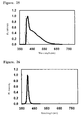
- fine BN particles synthesized by the above method when fine BN particles synthesized by the above method were irradiated with ultraviolet light having a wavelength of 365 nm, a peak of an emission spectrum was observed at a wavelength of 395 nm; fine BN particles that were observed to emit light had a low degree of crystallinity (degree of hexagonal crystallinity) and contained a large amount of oxygen (11.7% by weight), whereas fine BN particles that were not observed to emit light had a high degree of crystallinity and contained a small amount of oxygen (4.1% by weight).
- the B-N-O based amorphous oxynitride phosphors doped with Eu 2+ in an amount of 1 atm% or greater had an increased emission intensity at the wavelength of 372 nm;
- the B-N-O based amorphous oxynitride phosphors doped with Eu 2+ in an amount of 2.5 atm% or greater had a significantly increased emission intensity at the wavelength of 372 nm;
- the B-N-O based amorphous oxynitride phosphor doped with Eu 2+ in an amount of 5 atm% had a maximum emission intensity (Patent Citation 2).
- an inorganic electroluminescent device provided with a phosphor layer having phosphor particles comprising copper-doped zinc sulfide (Patent Citation 5), an inorganic electroluminescent device comprising not only zinc sulfide but also strontium sulfide (Non Patent Citation 1), and an inorganic electroluminescent device comprising cadmium selenide and zinc oxide (Patent Citation 6).
- an inorganic electroluminescent device comprising a compound such as barium thioaluminate (Non Patent Citation 2).
- Patent Citation 1 discloses that there is a relation between emission of light from the BN particles and the crystallinity of the particles and the amount of oxygen contained in the particles, details of the structure and luminous efficiency are not clear. Furthermore, there are operational problems that a step of reduction with hydrogen introduces complicated operations, and that a risk of explosions is high. There is also a practicality problem of lack of selectivity in wavelengths of light to be emitted.
- the B-N-O based oxynitride phosphor disclosed in Patent Citation 2 also includes a step of reduction with hydrogen, and therefore has the same problems of complicated operations and a high risk of explosions. Furthermore, since doping of Eu 2+ is required, there are problems that use of such an activator agent makes the operation complicated and that use of an expensive activator agent is required.
- Patent Citation 1 or 2 There are disclosed some techniques relating to BN or B-N-O based phosphors, as disclosed in Patent Citation 1 or 2.
- Patent Citations 3 and 4 disclose techniques relating to phosphors comprising Al and a carbon congener, including carbon, noting that rare-earth elements essentially act as light-emitting substances.
- M-C-N-O based phosphor that emits light in itself.
- Such M-C-N-O based phosphors do not comprise heavy metals and thus have high environmental compatibility.
- M-C-N-O based phosphors do not comprise rare metals and thus have economical advantages and are free of external factors such as availability of rare metals. Furthermore, development of such M-C-N-O based phosphors into white phosphors is also expected. Accordingly, there are social demands for such M-C-N-O based phosphors.
- an inorganic electroluminescent device having an M-C-N-O based phosphor as a phosphor layer material does not include sulfides and heavy metals in the phosphor layer and thus has a less environmental impact and contributes to resource conservation, compared with the inorganic electroluminescent devices disclosed in Patent Citations 5 and 6 and Non-patent Citations 1 and 2.
- Such an inorganic electroluminescent device having an M-C-N-O based phosphor as a phosphor layer material has excellent durability and low power consumption, compared with organic electroluminescent devices; thus, it is desired to use such an inorganic electroluminescent device in image displays such as lightweight, large flat panel displays.
- the present invention has an object to provide an M-C-N-O based phosphor that can be easily produced from inexpensive materials at a relatively low temperature without using heavy metals and rare metals, exhibits a high emission intensity without using any special activator agent, and has an emission spectrum with a peak top that can be adjusted to change a color.
- the present invention also has an object to provide a polymer dispersion or light emitting film comprising such an M-C-N-O based phosphor, and an inorganic electroluminescent device, light emitting device, or fluorescent tube having a phosphor layer comprising such an M-C-N-O based phosphor and having a simple structure that can emit light of various colors with a high luminous efficiency.
- the present inventors studied extensively and intensively and carried out various tests on M-C-N-O based phosphor devices that were variously adjusted, polymer dispersions or films comprising the devices, and inorganic electroluminescent devices, luminescent material devices, or fluorescent tubes having phosphor layers comprising the M-C-N-O based phosphors, and the present invention was accomplished.
- the present invention provides:
- the M-C-N-O based phosphor of the present invention can be easily produced from inexpensive materials at a relatively low temperature without using heavy metals and rare metals. Also, the M-C-N-O based phosphor of the present invention can emit light of various colors according to an amount of carbon contained.
- the M-C-N-O based phosphor of the present invention can be used to produce an inorganic electroluminescent device (hereinafter, inorganic EL device) having the M-C-N-O based phosphor in a phosphor layer to emit light of various colors.
- inorganic EL device inorganic electroluminescent device
- the M-C-N-O based phosphor of the present invention When excited by excitation light from an LED or laser diode, the M-C-N-O based phosphor of the present invention easily emits light of a color different from that of the LED or laser diode.
- a conventional LED or laser diode can be used to produce light emitting devices that emit light of various colors that were not previously obtained by using such a LED or laser diode.
- ultraviolet light from a fluorescent tube is used to induce emission of light from the M-C-N-O based phosphor of the present invention, an improvement in efficiency of the fluorescent tube can be achieved and also color of the fluorescent tube can be changed easily.
- An M-C-N-O based phosphor of the present invention essentially comprises a group IIIB element (M), carbon (C), nitrogen (N), and oxygen (O), and color of the phosphor changes according to an amount of carbon (C) contained.
- an amount of the group IIIB element (M) contained in the phosphor of the present invention be 1% ⁇ (M) ⁇ 50% by mass, an amount of carbon (C) contained in the phosphor of the present invention be 0.005% ⁇ (C) ⁇ 10% by mass, an amount of nitrogen (N) contained in the phosphor of the present invention be 1% ⁇ (N) ⁇ 60% by mass, and an amount of oxygen (O) contained in the phosphor of the present invention be 1% ⁇ (O) ⁇ 75% by mass.
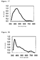
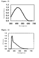
- the amount of carbon in the M-C-N-O based phosphor of the present invention may be changed to shift an emission wavelength of the phosphor and to produce emission of light of various fluorescent colors from the phosphor.
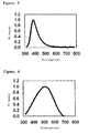
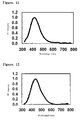
- a peak top of an emission spectrum of the M-C-N-O based phosphor of the present invention preferably varies in the wavelength range of 300-800 nm.
- a phosphor having an emission spectrum with a peak top that varies in the wavelength range of 400-650 nm is more useful.
- Carbon (C) is preferably contained in an amount of 0.005%-10% by mass.
- An excessively small amount of carbon (C) is not preferred, because this results in emission of light having a significantly short wavelength as well as lower intensity.
- An excessively large amount of carbon (C) is not preferred, because this results in not only a lower yield due to formation of impurities such as amorphous carbon but also absorption of emission energy by excess carbon. Accordingly, carbon is more preferably contained in an amount within the range of 0.01% to 9.0%.
- the M-C-N-O phosphor of the present invention can be obtained by mixing a group IIIB element-containing compound with a nitrogen-containing organic compound and then firing the mixture in a heating-firing furnace to produce a desired M-C-N-O based phosphor.
- the group IIIB element-containing compound for use in the present invention is not particularly limited, and may be any compound comprising a group IIIB oxide as a basic framework.
- Examples of compounds that can be used include boric acid, boric anhydride, derivatives of boric acid, such as esters, amides and ammonium salts, aluminic acid and derivatives of aluminic acid, such as esters, amides and ammonium salts, aluminum hydroxide, alumina, gallium hydroxide, gallium oxide, indium hydroxide, and indium oxide.
- boric acid, boric anhydride or ammonium salts of boric acid, aluminum hydroxide, gallium hydroxide or gallium oxide hydrate, or indium hydroxide It is also possible to use those compounds that are prepared by hydrolyzing other equivalent hydrochlorides, sulfates, or the like with a basic solution.
- Boric acid (B) is especially preferred.
- the nitrogen-containing organic compound for use in the present invention is not particularly limited, but may be any compound that decomposes to produce ammonia.
- nitrogen-containing organic compounds that can be used include: carbamide (i.e., urea); carbamates, such as methyl carbamate and ethyl carbamate; amides, such as formamide and acetamide; lactams, such as epsilon-caprolactam, gamma-butyrolactam, and N-methylpyrrolidone; and ammonium salts, such as ammonium formate and ammonium acetate.
- carbamide, amides, and ammonium salts are preferred; in view of economical efficiency and ease of handling, carbamide is especially preferred.
- the mixture of the group IIIB element-containing compound and the nitrogen-containing organic compound may further comprise a dispersing agent.
- the dispersing agent not only serves as a source of carbon for the M-C-N-O based phosphor but also facilitates reaction of the group IIIB element-containing compound with the nitrogen-containing organic compound.
- the dispersing agent also improves dispersibility of the boron-containing compound and the nitrogen-containing organic compound in the solvent so that preferential precipitation of only one of those compounds can be prevented when the solvent volatilizes.
- the dispersing agent to be used is not particularly limited, and various dispersing agents can be used, but it is preferable to use a dispersing agent having high affinity especially to the group IIIB element-containing compounds.
- the dispersing agent has a boiling point that is higher than a temperature at which ammonia is produced by decomposition of the nitrogen-containing organic compound.
- Examples of compounds having high affinity to the group IIIB element-containing compounds include: polyethers, such as polyethylene glycol (PEG), polyethylene glycol dimethyl ether, and polyethylene oxide; polyamides, such as polyvinyl pyrrolidone; macromolecular compounds, such as hydroxyl polymers such as polyvinyl glycerin and polyvinyl alcohol; polyalcohols, such as ethylene glycol, 1,2-propanediol, 1,3-propanediol, 1,2-butanediol, 1,4-butanediol, glycerin, diethylene glycol, triethylene glycol, and tetraethylene glycol; ethers, such as dimethoxyethane, 1,2-propanediol dimethyl ether, 1,3-propanediol dimethyl ether, 1,2-butanediol dimethyl ether, 1,4-butanediol dimethyl ether, glycerin trimethyl ether
- the M-C-N-O based phosphor can be obtained by heating and firing the mixture, which may optionally comprise the dispersing agent.
- the M-C-N-O based phosphor can be obtained by dissolving or suspending the mixture in the solvent, and then heating and firing the solution or suspension.
- the solvent is not particularly limited, and any solvent may be used that can dissolve the group IIIB element-containing compound and the nitrogen-containing organic compound and can maintain dispersibility of those compounds.
- any solvent may be used that can dissolve the group IIIB element-containing compound and the nitrogen-containing organic compound and can maintain dispersibility of those compounds.
- water and alcohols such as methanol and ethanol, can be used. In view of safety in use, explosiveness, and the like, it is preferable to use water.
- the solvent to be used contain no impurity. Especially contamination of the solvent with alkali metals and alkali earth metals is unfavorable, because there is concern that alkali metals and alkali earth metals react with the group IIIB element-containing compound to cause structural changes, which may affect emission of light. Contamination of the solvent with heavy metals is also unfavorable, because there is concern that heavy metals may have an effect on formation of a structure of the M-C-N-O based phosphor. Contamination of the solvent with halogens or the like is unfavorable, because halogens expedite decomposition of the nitrogen-containing organic compound and inhibit incorporation of nitrogen into the M-C-N-O based phosphor. Accordingly, preferably a total amount of these impurities contained is 5000 ppm or smaller, more preferably 1000 ppm or smaller.
- Amounts of the group IIIB element-containing compound and nitrogen-containing organic compound to be used cannot be generally specified, because the amounts depend on types of compounds to be used, firing temperature and time, and the like, but 10-1500 parts by weight, preferably 50-1200 parts by weight, of the nitrogen-containing organic compound is generally used with respect to 100 parts by weight of the group IIIB element-containing compound.
- An amount of the dispersing agent to be used is not particularly limited, and cannot be generally specified, because it depends on a type of a compound to be used, firing temperature and time, and the like. However, it is generally preferable to use 1-200 parts by weight, preferably 5-190 parts by weight, of the dispersing agent with respect to 100 parts by weight of the group IIIB element-containing compound.
- An amount of the solvent to be used in the present invention is not particularly limited, and cannot be generally specified, because it depends on a type of a compound to be used, firing temperature and time, and the like. However, it is generally preferable to use 1-50000 parts by weight, more preferably 10-10000 parts by weight, of the solvent with respect to 100 parts by weight of the group IIIB element-containing compound. Use of the solvent in an excessively large amount is uneconomical, because a longer period of time and a greater heat quantity are required to remove the solvent. Thus, it is more preferable to use 20-5000 parts by weight of the solvent.
- the mixture of the group IIIB element-containing compound and the nitrogen-containing organic compound, and optionally a dispersing agent, or the solution or suspension prepared by dissolving the mixture in the solvent is heated and fired according to the present invention.
- a mixing method for the preparation of the mixture, or the solution or suspension prepared by dissolving the mixture in the solvent is not particularly limited.
- a mixing method using a ball mill, turbo mill, jet mill, mortar, or the like can be used for solid-solid mixing.
- heating and firing may be carried out by any method that enables pyrolysis of the mixture or the solution containing the mixture to take place.
- heating and firing methods that can be used in the present invention include those using a heating-firing furnace with a movable bed, such as a rotary kiln and a conical kiln, those using heating-firing furnace with a continuous fixed bed, such as a roller hearth furnace and a pusher furnace, those using a heating-firing furnace with a batch fixed bed, such as an atmosphere adjusting furnace, or those using a pyrolysis furnace such as a spray or atomization method.
- the heating and firing methods are not particularly limited; the temperature may be increased to a target temperature in a single step, or may be increased through multiple steps.
- the temperature is not preferable to increase the temperature at an excessively fast rate, because sudden boiling (i.e., bumping) may occur when heat transfer is poor.
- the temperature is generally increased by 1-30°C per minute, preferably 5-25°C per minute.
- the temperature is increased by 1-30°C per minute until it reaches a boiling point, maintained at or near the boiling point for 10-120 minutes, increased by 1-30°C per minute until it reaches a decomposition temperature of the nitrogen-containing organic compound, maintained, when necessary, for 10-120 minutes, and then increased by 1-30°C per minute until it reaches a target temperature.
- a firing temperature cannot be generally specified, because it depends on the amount of the nitrogen-containing organic compound used, the amount of the dispersing agent used, and the like, but the firing temperature is generally set within the range of 300°C to 1000°C.
- An excessively high temperature is likely to result in carbon vacancies and decreased brightness or a deviation from a desired wavelength.
- an excessively low temperature does not result in improvement in brightness, because it does not allow crystallization to proceed.
- the firing may be carried out at a temperature of 320°C to 900°C, more preferably 350°C to 850°C.
- a period of maintaining the firing temperature cannot be definitely determined, because it depends on the amount of the nitrogen-containing organic compound used and the amount of the dispersing agent used, but the period is generally set within the range of 0-180 minutes.
- An excessively short period is not preferred, because it may result in insufficient heat transfer, which is likely to arise a problem concerning homogeneity.
- An excessively long period is not preferred, because it may result in carbon vacancies. Accordingly, the firing temperature may be maintained for a period of 1-150 minutes, more preferably 5-120 minutes.
- the heating and firing may be carried out in the presence of an inert gas (in the absence of oxygen) or in an atmosphere (in the presence of oxygen). However, in the case of heating and firing the mixture without addition of the dispersing agent or solvent, the heating and firing may be carried out in the absence of oxygen.
- the heating and firing may be preferably carried out in the presence of oxygen to remove excess carbon by combustion.
- a concentration of oxygen is not particularly limited, but typically may be in the range of 1% to 30%, more preferably in the range of 3% to 25%.
- the firing atmosphere can be adjusted through multiple stages. For example, when the temperature is 400°C or lower, at which the combustion level is low, the firing may be carried out in an atmosphere of an inert gas, such as nitrogen, in view of the risks of explosions by ammonia produced by decomposition of the nitrogen-containing organic compound. On the other hand, when the temperature is 400°C or higher, at which the combustion level is high, the firing may be carried out in the presence of oxygen. During the firing step, further formation of carbon vacancies can be inhibited by using an inert gas atmosphere as the firing atmosphere while maintaining the target temperature. The foregoing procedures can be performed in a gas stream or in a closed atmosphere.
- the rate of decreasing the temperature is not particularly limited. However, an excessively fast rate is unfavorable, because it requires a special firing furnace which is likely to impose unfavorable burden on facilities. Accordingly, the temperature is preferably decreased by 1-80°C per minute, more preferably 2-50°C per minute.
- the atmosphere in which the temperature is to be decreased is not particularly limited; the temperature may be decreased in an atmosphere of an inert gas, such as nitrogen and argon, or in the presence of oxygen. In view of safety and the like, the temperature is preferably decreased in an inert gas. When the temperature is 300°C or lower, moisture adheres to a target phosphor surface; thus, the temperature is preferably decreased in dry gas.
- Particles of the M-C-N-O based phosphor obtained by the above methods may take various shapes, and may include, for example, primary particles having an average particle size of 1 nm to 10 ⁇ m, as measured by a light scattering method, and aggregates of the primary particles in the range of submicrons to several microns, as measured by a light scattering method.
- these M-C-N-O based phosphor particles may be used directly, or may be ground into finer particles for a particular use. To grind the particles, a ball mill, jet mill, or turbo mill may be used. Particles prepared using a binder may also be used.
- the foregoing describes the M-C-N-O based phosphor of the present invention and the method for the production of the M-C-N-O based phosphor.
- the M-C-N-O based phosphor of the present invention is applicable to inorganic EL devices, light emitting devices, fluorescent lamps, and the like, in which the M-C-N-O based phosphor used emits light of various colors with high energy efficiency.
- the polymer dispersion suitable for use in the production of the inorganic EL devices, light emitting devices, or fluorescent lamps is described below.
- a dispersion prepared by dispersing the M-C-N-O based phosphor into a dispersion comprising polymers of resins listed below may be used as the polymer dispersion.
- polymers of the following resins can be used: cyanoethylpullulan and cyanoethylcellulose; polyfluoride resins, such as polytetrafluoroethylene, poly(trifluoroethylene), and poly(vinylidene fluoride); polycarbonate resins; polyolefin resins, such as polyethylene and polypropylene; polystyrene resins; polyacrylic acid ester resins, such as poly(methyl acrylate) and poly(methyl methacrylate); polyacrylamide resins; polyester resins, such as polyethylene terephthalate and polybutylene terephthalate; polyamide resins, such as 6-nylon and 6,6-nylon; dicyclopentadiene ring-opening polymer hydrogenation resins; hydrogenated styrene
- Resins to be used for the present invention are preferably selected from polycarbonates, polyamides, polyacrylic acid esters, polymethacrylic acid esters, polyacrylamides, polymethacrylamides, and thermosetting resins obtained from silicone resins or epoxy resins.
- the M-C-N-O based phosphor is dispersed into such a dispersion to prepare a polymer dispersion containing the M-C-N-O based phosphor.
- the M-C-N-O based phosphor can be dispersed into the polymer dispersion by a dispersion method using a homogenizer, planetary kneader, roll kneader, ultrasonic dispersing apparatus, or the like.
- the M-C-N-O based phosphor-containing polymer dispersion thus obtained can be suitably used in the production of dispersion-type inorganic EL devices described below.
- the following describes the dispersion-type inorganic EL device (hereinafter, dispersion-type EL device) of the present invention.
- the dispersion-type EL device may have a known structure in which a phosphor layer is provided between conductive electrodes, at least one of which is a counterpart of an electrode having a light-transmitting transparent conductive film. Specific structures are as follows.
- the phosphor layer is formed using the polymer dispersion described above. Specifically, the phosphor layer is formed by application of the polymer dispersion onto a substrate by spin coating, dip coating, bar coating, or spraying and then dried by heating at 50-300°C to form a layer with a desired thickness.
- the above application techniques those applicable to any surface of any substrate to be printed, such as screen printing, and those capable of continuous application, such as slide coating, are preferred.
- a dispersion prepared by dispersing fine phosphor and dielectric particles into a polymer solution having a high permittivity is applied through a screen mesh by using a screen printing technique.
- the thickness of the layer may be controlled by selecting a thickness of the mesh, an aperture ratio, and the number of applications. An area of the layer can be easily enlarged by changing a size of the screen.
- a concentration of the M-C-N-O based phosphor in the polymer dispersion is not particularly limited, but it should be understood that the concentration depends the particle size of the M-C-N-O based phosphor. However, it is generally preferable that the concentration be in the range of 1-80 % by weight; in view of dispersibility and efficient use of ultraviolet light, it is preferable to use in the range of 2-70 % by weight.
- the phosphor layer has a thickness of 300 nm to 30 ⁇ m, and particularly preferably 500 nm to 10 ⁇ m.
- the wavelength of light to be emitted from the phosphor layer can be controlled by adjusting the amount of amide compounds to be added and the firing temperature, and thus any wavelength in the visible light range can be obtained.
- a material that emits blue light of about 460 nm can be prepared by mixing boric acid with carbamide at a molar ratio of 1:1, optionally adding as a dispersion material 10% by weight of polyethylene glycol with respect to the mixture, and firing the resulting mixture in a crucible at 700°C in an atmosphere.
- the M-C-N-O based phosphor is directly dispersed, but the M-C-N-O based phosphor may be coated with a non-light-emitting shell layer and then dispersed into the phosphor layer.
- the products disclosed in Japanese patent No. 2756044 and United States patent No. 6458512 may be used, in which phosphors are coated with a non-light-emitting shell layer comprising a metal oxide or metal nitride and having a thickness of 0.01 ⁇ m or greater. Such coating may produce a waterproof, water-resistant phosphor layer.
- the non-light-emitting shell layer may comprisean oxide, nitride, oxynitride, or a material having the same composition as that of the host phosphor particles but without a luminescent center, which may be produced on the phosphor particles.
- vapor phase methods such as laser abrasion, CVD, plasma CVD, and a combination of sputtering, resistance heating, or electron beam method with vapor deposition onto a running oil substrate
- liquid phase methods such as double decomposition, sol-gel process, ultrasonic chemical process, precursor pyrolysis reaction, inverse micelle process, a combination of these processes with high-temperature firing, hydrothermal synthesis, carbamide melting, and freeze drying
- spray pyrolysis vapor phase methods, such as laser abrasion, CVD, plasma CVD, and a combination of sputtering, resistance heating, or electron beam method with vapor deposition onto a running oil substrate
- liquid phase methods such as double decomposition, sol-gel process, ultrasonic chemical process, precursor pyrolysis reaction, inverse micelle process, a combination of these processes with high-temperature firing, hydrothermal synthesis, carbamide melting, and freeze drying
- spray pyrolysis such as spray pyrolysis.
- the dispersion-type EL device of the present invention may have a dielectric layer comprising a dielectric substance between the phosphor layer and the rear electrode.
- the dielectric substance may be in the form of a thin crystal layer, particles, or a combination thereof.
- the dielectric layer comprising the dielectric substance may be provided to one side or both sides of the phosphor particle layer. Any material that has a high permittivity, high insulation properties, and a high dielectric breakdown voltage can be used in the dielectric layer
- the dielectric substance is selected from metal oxides and metal nitrides.
- the dielectric substances to be used may include, for example, barium titanate, potassium niobate, lithium niobate, lithium tantalate, tantalum oxide, or alumina. These substances may be applied as a uniform layer by sputtering, vacuum vapor deposition, or the like, or as a layer having a structure of particles comprising an organic binder. In the case of the particles, it is preferable that the dielectric substance be adequately small with respect to a size of the phosphor particles. Specifically, it is preferable that the size of the dielectric substance be 1/1 to 1/100 of the size of the phosphor particles.
- the type of the binder, the method of dispersion into the binder, and the layer forming method may be the same as those for the phosphor layer.
- any commonly used transparent electrode materials may be used in the transparent conductive layer of the dispersion-type EL device of the present invention.
- transparent electrode materials to be used include metal oxides, such as tin doped tin oxide, antimony doped tin oxide, zinc doped tin oxide, fluorine doped tin oxide, and zinc oxide, materials having a multilayer structure in which a thin silver layer is sandwiched between layers having a high index of refraction, and conjugated polymers, such as polyaniline and polypyrrole.
- tin oxide is preferably used as a main component of a surface of the transparent conductive layer, because it improves durability of the transparent conductive layer.
- the transparent conductive layer has a surface resistivity of 0.01 ⁇ /m 2 to 100 ⁇ /m 2 , more preferably 0.02 ⁇ /m 2 to 10 ⁇ /m 2 .
- An amount of the applied transparent conductive substance is preferably 100% by mass to 10% by mass, more preferably 90% by mass to 15% by mass, with respect to the transparent conductive layer.
- the transparent conductive layer can be formed by a vapor-phase method such as sputtering or vacuum vapor deposition.
- the transparent conductive layer can be formed by applying or screen-printing an ITO or tin oxide paste. It is also possible to form the layer by a thermal method such as spray pyrolysis. According to one embodiment of the present invention, a transparent film having higher thermal resistance is preferred.
- the dispersion-type EL device of the present invention may comprise a transparent electrode layer, a light emitting layer, and/or at least one intermediate layer between the rear electrode and the dielectric layer.
- the intermediate layer may comprise an organic macromolecular compound, an inorganic compound, or a combination thereof.
- the intermediate layer has a thickness of 10 nm to 10 ⁇ m, more preferably 100 nm to 1 ⁇ m.
- the macromolecular compound includes: polyethylene, polypropylene, polystyrene, polyesters, polycarbonates, polyamides, polyethersulfones, polyvinyl alcohol, polysaccharides such as pullulan, saccharose, and cellulose, vinyl chloride, fluorine rubber, polyacrylic acid esters, polymethacrylic acid esters, polyacrylamides, polymethacrylamides, silicone resins, cyanoethylpullulan, cyanoethylpolyvinyl alcohol, cyanoethylsaccharose, and mixtures thereof.
- the intermediate layer can be formed by dissolving any of these organic macromolecular compounds in a suitable organic solvent, such as dichloromethane, chloroform, acetone, methyl ethyl ketone, cyclohexanone, acetonitrile, dimethylformamide, dimethylacetamide, dimethyl sulfoxide, toluene, and xylene, and then applying the mixture onto the transparent conductive layer or phosphor layer.
- a suitable organic solvent such as dichloromethane, chloroform, acetone, methyl ethyl ketone, cyclohexanone, acetonitrile, dimethylformamide, dimethylacetamide, dimethyl sulfoxide, toluene, and xylene
- the intermediate layer may comprise an inorganic compound such as metal oxides (e.g., silicon dioxide) and metal nitrides.
- the method for forming the intermediate layer from an inorganic compound includes sputtering, CVD, or the like.
- the intermediate layer preferably has a thickness of 10 nm to 1 ⁇ m, more preferably 10 nm to 200 nm.
- Conductive materials can be used in the rear electrode from which no light is to be obtained.
- metals such as gold, silver, platinum, copper, iron, magnesium, and aluminum, or graphite can be used.
- An appropriate material is selected from these materials in view of a form of a device to be produced, a temperature during the production, and the like. These materials can be used singly or in combination.
- a thickness of the electrode is not particularly limited, but it is generally preferable that the electrode have a thickness of 100 nm to 100 ⁇ m, more preferably 500 nm to 50 ⁇ m.
- the substrate material for use in the dispersion-type EL device of the present invention is not particularly limited, and may include any substrate that has adequate shielding properties to eliminate the effects of external moisture and oxygen. Materials having excellent shielding properties, such as glass and polyethylene terephthalate, are typically used for the substrate.
- a thickness of the substrate is not particularly limited. When the substrate is made of glass, it is generally preferable that the substrate have a thickness of 10 ⁇ m to 2 mm, more preferably 14 ⁇ m to 1 mm. When the substrate is made of polyethylene terephthalate or the like, the substrate preferably has a thickness of 10 ⁇ m to 1 mm, more preferably 15 ⁇ m to 500 ⁇ m.
- Thin-film inorganic EL devices can have the same structure as that of the dispersion-type EL device and can be produced by the same method as that for producing the dispersion-type EL device, except for the production of the phosphor layer.
- the phosphor layer of the thin-film EL device is formed as follows. The phosphor layer can be formed by directly subjecting to pyrolysis or electrostatic spray deposition the mixture of the group IIIB element-containing compound and the nitrogen-containing organic compound and optionally the dispersing agent, or the solution or suspension containing the mixture.
- the phosphor layer can be formed by providing the M-C-N-O based phosphor, and subsequently subjecting it to a vapor phase process, such as sputtering and vacuum vapor deposition.
- a vapor phase process such as sputtering and vacuum vapor deposition.
- the phosphor layer has a thickness of 200 nm to 30 ⁇ m.
- the phosphor layer has a thickness of 200 nm to 1 ⁇ m.
- the dispersion-type EL device or thin-film EL device comprises environmentally-friendly elements and can produce light of various, previously unavailable colors, while having a simple structure and retaining advantages of conventional inorganic EL devices.
- the polymer dispersion containing the M-C-N-O based phosphor of the present invention can be suitably used in the production of a light emitting device described below.
- the light emitting device like the inorganic EL devices of the present invention, comprises environmentally-friendly elements and can produce light of various, previously unavailable colors, while having a simple structure and retaining advantages of conventional LEDs or laser diodes.
- the light emitting device of the present invention may be produced by, for example, applying the polymer dispersion onto an outer or inner surface of a transparent resin section surrounding a light emitting section of an LED or laser diode, and then drying the solution.
- the light emitting device may be produced by applying the polymer dispersion directly onto a light emitting section of an LED or laser diode, and then drying the solution.
- the light emitting device of the present invention may be produced such that the M-C-N-O based phosphor is provided above or in front of the light emitting section of the LED or laser diode.
- the M-C-N-O based phosphor may be provided such that the phosphor is efficiently excited by excitation light from the LED or laser diode.
- an ethylene tetrafluoride resin film to which the polymer dispersion is applied may be attached to a light emitting device of an LED, or alternatively a film of the polymer dispersion may be prepared and attached to a light emitting device of an LED.
- These films function as light emitting films that emit light when excited by excitation light from the light emitting section of the LED.
- methods for forming a film from the polymer dispersion include casting or stretching the polymer dispersion to form a film.
- the light emitting device of the present invention may be directly produced in the production of the LED or laser diode by dispersing the M-C-N-O based phosphor into a polymer that serves as a material for protecting the LED or laser diode, and then molding the resulting dispersion.
- LEDs or laser diodes can be used in the light emitting device of the present invention, but LEDs or laser diodes that emit ultraviolet light, such as GaN based crystals, are preferred.
- LEDs or laser diodes that emit ultraviolet light, such as GaN based crystals.
- the use of such LEDs or laser diodes makes it possible to produce a light emitting device having high energy efficiency.
- the concentration of the M-C-N-O based phosphor in the polymer dispersion be in the range of 1-80% by weight, but it should be understood that the concentration depends on the composition and the particle size of the M-C-N-O based phosphor.
- the concentration of the M-C-N-O based phosphor in the polymer dispersion is preferably within the range of 2-70 % by weight.
- a thickness of the phosphor layer to be excited by the LED or laser diode is not particularly limited, regardless of conditions and methods of forming the phosphor layer.
- an excessively thick phosphor layer is likely to have decreased luminous efficiency due to light scattering by particles, and an excessively thin phosphor layer may result in inefficient use of ultraviolet light.
- the phosphor layer preferably has a thickness of 10-500 ⁇ m.
- the LED or laser diode that emits light of various colors can be obtained by providing the M-C-N-O based phosphor of the present invention above or in front of a conventional LED or laser diode such that the LED or laser diode may emit light through the M-C-N-O based phosphor.
- organic combination of the LED or laser diode and the M-C-N-O based phosphor can provide a luminescent body that is small and lightweight and has a long lifetime and low power consumption.
- the LEDs or laser diodes of previously unavailable colors can be easily obtained, which retain advantages of the LEDs or laser diodes.
- the LED or laser diode of various colors can be easily produced simply by changing the materials of the M-C-N-O based phosphor to be provided to the light emitting device of the present invention without changing a structure of the LED or laser diode.
- the present invention solves the problem that the production of the LED or laser diode of various colors requires a different material for each color of light to be emitted and a different apparatus for each material.
- the present invention requires fewer apparatuses and simplifies the production steps, and accordingly has an advantage that production costs are significantly reduced.
- characteristics of the LED or laser diode that emits excitation light do not change even when the materials of the phosphor are changed, it is possible to easily obtain LEDs or laser diodes with the same electrical characteristics and different fluorescent colors. This makes it possible to use the same driving circuit to cause emission of light when devices that emit light of different colors are used, while it was conventionally required to change the driving circuit for each characteristic of the LED or laser diode; thus, the driving system can be simplified.
- the light emitting device of the present invention is applicable to the uses of LEDs or laser diodes that are widely used as display devices. Furthermore, according to of the present invention, the light emitting device that emits light of an intermediate color or white light can be easily obtained. Thus, the light emitting device of the present invention is further applicable to display lamps and illuminating lamps of instruments that require a large number of colors, though conventional LEDs or laser diodes were not applicable.
- a fluorescent tube having high energy efficiency can be easily produced by using the polymer dispersion comprising the M-C-N-O based phosphor, as described below.
- the fluorescent tube of the present invention is produced by, for example, applying the polymer dispersion onto a surface of a fluorescent tube and then drying the dispersion.
- the fluorescent tube like the light emitting device described above, may be produced such that ultraviolet light from the fluorescent tube can efficiently irradiate the phosphor layer comprising the M-C-N-O based phosphor that is provided above the surface of the tube.
- the fluorescent tube may be any tube that emits ultraviolet light; such tubes that can be referred to as any name can be used, e.g., fluorescent lamps, cold-cathode tubes, and ultraviolet lamps.
- fluorescent lamps e.g., fluorescent lamps, cold-cathode tubes, and ultraviolet lamps.
- Application of the fluorescent tube to general lamps provides a lamp that can emit fluorescent light with an improved efficiency.
- the concentration of the M-C-N-O based phosphor in the polymer dispersion may be the same as that used in the production of the light emitting device described above.
- the thickness of the phosphor layer to be excited by excitation light emitted from the fluorescent tube is not particularly limited. However, an excessively thick phosphor layer is likely to have lower luminous efficiency due to light scattering by particles, and an excessively thin phosphor layer may result in inefficient use of ultraviolet light. Thus, the phosphor layer preferably has a thickness of 10-500 ⁇ m.
- the phosphor layer can be produced by various methods as in the case of the inorganic EL device; for example, the phosphor layer can be produced by attaching the light emitting film.
- the foregoing describes the fluorescent tube of the present invention.
- the present invention can provide a fluorescent tube having high energy efficiency. Further, the present invention permits use of near-ultraviolet radiation that is conventionally unused, and therefore enables the production of environmentally-friendly fluorescent tubes that not only improve energy efficiency but also efficiently utilize radiation that is likely to have potential adverse effects on human bodies when used in short distances. Further, the fluorescent tube of colors that cannot be realized by conventional fluorescent lamps, cold-cathode tubes, and ultraviolet lamps can be easily produced according to the present invention.
- Fig. 1 The ultraviolet excitation-emission spectrum of the phosphor obtained in Example 1 is shown in Fig. 1 .
- the horizontal axis indicates a wavelength
- the vertical axis indicates a PL intensity (photoluminescence (PL) intensity).
- PL photoluminescence
- Amounts of elements contained in the phosphor obtained in Example 1 are shown in Table 1, and a peak-top emission wavelength is shown in Table 2.
- Example 2 The procedure of Example 1 was repeated, except that the firing temperature was 900°C. Amounts of elements contained are shown in Table 1, and a peak-top emission wavelength is shown in Table 2. The result of XPS measurement performed on the phosphor is shown in Fig. 2 (No.2). The ultraviolet excitation-emission spectrum is shown in Fig. 3 .
- Example 2 The procedure of Example 1 was repeated, except that 1.0 g of PEG was used instead of 0.5g of PEG. Amounts of elements contained are shown in Table 1, and a peak-top emission wavelength is shown in Table 2. The result of XPS measurement performed on the phosphor is shown in Fig. 2 (No.3). The ultraviolet excitation-emission spectrum is shown in Fig. 4 .
- Example 2 The procedure of Example 1 was repeated, except that 1.375 g of PEG was used instead of 0.5 g of PEG. Amounts of elements contained are shown in Table 1, and a peak-top emission wavelength is shown in Table 2. The result of XPS measurement performed on the phosphor is shown in Fig. 2 (No.4). The ultraviolet excitation-emission spectrum is shown in Fig. 5 .
- Example 1 Amount of boron contained (%) Amount of carbon contained (%) Amount of nitrogen contained (%) Amount of oxygen contained (%)
- Example 1 29.2 0.4 9.0 61.4
- Example 2 27.3 1.0 20.6 48.7
- Example 3 25.2 2.2 16.0 56.6
- Example 4 18.8 4.5 5.3 71.4
- Example 5 The ground mixture of Example 5 was added to 20 g of ion exchange water and dissolved. The resulting solution was placed under a reduced pressure of 70 Torr and heated at 100°C to evaporate the added water. Then, a mixture paste was obtained. The resulting paste was placed in an alumina boat. Then, the alumina boat was placed in a cylindrical tubular furnace, heated to 800°C in the atmosphere at a rate of 20°C per minute, maintained at 800°C for 20 minutes, and then allowed to cool down in nitrogen. The ultraviolet excitation-emission spectrum of the resulting phosphor is shown in Fig. 7 .
- Example 5 The procedure of Example 5 was repeated, except that tetraethylene glycol was used in place of PEG.
- the ultraviolet excitation-emission spectrum of the resulting phosphor is shown in Fig. 8 .
- Example 5 The procedure of Example 5 was repeated, except that glycerin was used in place of PEG.
- the ultraviolet excitation-emission spectrum of the resulting phosphor is shown in Fig. 9 .
- Example 5 The procedure of Example 5 was repeated, except that no PEG was used.
- the ultraviolet excitation-emission spectrum of the resulting phosphor is shown in Fig. 10 .
- Example 5 The procedure of Example 5 was repeated, except that boric anhydride was used in place of boric acid.
- the ultraviolet excitation-emission spectrum of the resulting phosphor is shown in Fig. 11 .
- Example 5 The procedure of Example 5 was repeated, except that ammonium borate was used in place of boric acid.
- the ultraviolet excitation-emission spectrum of the resulting phosphor is shown in Fig. 12 .
- Example 5 The procedure of Example 5 was repeated, except that ethyl carbamate was used in place of carbamide.
- the ultraviolet excitation-emission spectrum of the resulting phosphor is shown in Fig. 13 .
- Example 5 The procedure of Example 5 was repeated, except that acetamide was used in place of carbamide.
- the ultraviolet excitation-emission spectrum of the resulting phosphor is shown in Fig. 14 .
- Example 5 The procedure of Example 5 was repeated, except that ammonium formate was used in place of carbamide.
- the ultraviolet excitation-emission spectrum of the resulting phosphor is shown in Fig. 15 .
- Example 9 The procedure of Example 9 was repeated, except that the procedure was carried out in a nitrogen atmosphere.
- the ultraviolet excitation-emission spectrum of the resulting phosphor is shown in Fig. 16 .
- Example 1 One gram of the phosphor that was obtained in Example 1 was placed in a quartz boat, and an inner system of a cylindrical reaction tube that was heated to a predetermined temperature was purged with nitrogen. Thereafter, ammonia gas and argon gas were fed to carry out nitriding treatment. The gases were fed at 500 sccm. After 600-minute nitriding treatment, the sample was allowed to cool to room temperature in nitrogen gas and then recovered in a nitrogen atmosphere. Measurement of an amount of oxygen was carried out, but no oxygen was detected. No emission of fluorescent light by ultraviolet excitation was observed.
- Example 11 The procedure of Example 11 was repeated, except that no carbamide was added. No carbon was detected in the resulting firing product. No emission of fluorescent light by ultraviolet excitation was observed.
- Example 1 The procedure of Example 1 was repreated, except that diphenyl carbonate was used. No nitrogen was detected in the resulting firing product. No emission of light by ultraviolet excitation was observed.
- Example 1 The procedure of Example 1 was repeated, except that no boric acid was used. No boron was detected in the resulting firing product. No carbon emission by ultraviolet excitation was observed.
- a fluorine based binder (DuPont 7155) was added as the binder, and the mixture was defoamed to produce a light emitting layer paste.
- a layer with a thickness of 40 ⁇ m was formed on an ITO-bearing PET film by use of a 20-mm square screen mask (200 mesh, 25 ⁇ m).
- a layer of a barium titanate paste (DuPont 7153) was formed using a screen mask (150 mesh, 25 ⁇ m). After drying at 100°C for 10 minutes, layers were formed again and dried at 100°C for 10 minutes to produce a 20 ⁇ m dielectric layer.
- a layer of a silver paste (Acheson 461SS) was formed as an electrode on the dielectric layer by use of a screen mask (150 mesh, 25 ⁇ m) and dried at 100°C for 10 minutes to produce an electrode, whereby a dispersion-type EL device was produced.
- the resulting device was subjected to EL material evaluation at 200 V and 1 kHz.
- the obtained EL emission spectrum is shown in Fig. 20 , and the results are shown in Table 3.
- Example 19 The procedure of Example 19 was repeated, except that 19.2 g of carbamide was used in place of 30.6 g of carbamide, 2.0 g of polyethylene glycol was used in place of 1.0 g of polyethylene glycol, and the firing temperature was 700°C.
- the obtained EL emission spectrum is shown in Fig. 21 , and the results are shown in Table 3.
- the following Examples illustrate the light emitting device comprising in the phosphor layer the M-C-N-O based phosphor of the present invention.
- the light emitting device included a GaN based ultraviolet LED in a light emitting section.
- Example 21 The procedure of Example 21 was repeated, except that 19.2 g of carbamide was used in place of 30.6 g of carbamide, 2.0 g of polyethylene glycol was used in place of 1.0 g of polyethylene glycol, and the firing temperature was 700°C.
- the obtained LED emission spectrum is shown in Fig. 23 .
- Example 21 The procedure of Example 21 was repeated, except that the dispersion product was applied with a thickness of 10 ⁇ m onto an inner surface of the transparent resin section. The results were almost the same as those in Example 21. The obtained LED emission spectrum is shown in Fig. 24 .
- Example 21 The procedure of Example 21 was repeated, except that the dispersion product was applied with a thickness of 20 ⁇ m onto a surface of the light emitting device.
- the obtained LED emission spectrum is shown in Fig. 25 . It shows that ultraviolet light was converted into blue light.
- the following Examples illustrate the fluorescent tube comprising in the phosphor layer the M-C-N-O based phosphor of the present invention.
- a commercially available 15-W fluorescent lamp was used.
- a solution containing 46% polyvinyl alcohol and 54% water was added to 100 mg of the resulting phosphor, and the resulting mixture was further ground in the mortar, whereby the phosphor particles were dispersed into the mixture.
- the resulting mixture was applied with a thickness of 20 microns onto an ethylene tetrafluoride resin sheet by a bar-coater and then dried at 40°C to obtain a phosphor-dispersed film (light emitting film) having a thickness of 16 microns.
- the emission spectrum of the resulting film is shown in Fig. 27 .
- the resulting film was attached to the 15-W fluorescent lamp, and an illuminance at a point 40 cm below the film was measured by Illuminometer T-10wp manufactured by Konica Minolta Holdings, Inc; the illuminance was 577 lx. Since an illuminance of a fluorescent lamp without the light emitting film was 550 lx, it is recognized that the attachment of light emitting film improved the illuminance of the fluorescent lamp by 27 lx.
- Example 26 Ten grams of a solution containing 46% polyvinyl alcohol and 54% water were added to 100 mg of the phosphor that was obtained in Example 25, and the resulting mixture was further ground in the mortar, whereby the phosphor particles were disperse into the mixture. The resulting mixture was applied with a thickness of 16 microns onto a surface of the 15-W fluorescent lamp. After the applied solution was dried, an illuminance at a point 40 cm below the film was measured by Illuminometer T-10wp manufactured by Konica Minolta Holdings, Inc; the illuminance was 582 lx. In Example 26, an illuminance of the common fluorescent lamp was improved by 32 lx.
- Example 19 50 mg of the phosphor that was obtained in Example 19 and 50 mg of the phosphor that was obtained in Example 2 were ground and mixed, and 10 g of a solution containing 46% polyvinyl alcohol and 54% water was added to the mixture. The resulting mixture was further ground in the mortar, whereby the phosphor particles were dispersed into the mixture.
- the dispersion product was applied onto a surface of the GaN based ultraviolet LED and dried at 60°C. A voltage of 4.2 V was applied to the ultraviolet LED having the dispersion product with a thickness of 20 ⁇ m on an outer surface of a transparent resin section. The obtained LED emission spectrum is shown in Fig. 28 .
- the emission spectrum curve has two peaks, indicating that ultraviolet rays were respectively converted by the two phosphors.
- the phosphor layer can be produced that exhibits not only the foregoing emission spectrum curve having two peaks but also an emission spectrum curve having a plurality of desired peaks.
- the present invention can provide the phosphor layer comprising the M-C-N-O based phosphor having a plurality of different emission peaks.
- the M-C-N-O based phosphor of the present invention can be easily produced from inexpensive materials at a relatively low temperature without using heavy metals and rare metals.
- the M-C-N-O based phosphor of the present invention can provide luminescent materials of various wavelengths depending on the amount of carbon contained; thus, the M-C-N-O based phosphor of the present invention can be used as phosphors for CRT, PDP, and the like.
- the polymer dispersion or light emitting film comprising the M-C-N-O based phosphor of the present invention can be used to produce various fluorescent/luminescent materials having high environmental compatibility and emitting light of various, previously unavailable colors, such as inorganic EL devices, light emitting devices using excitation light from LEDs or laser diodes, and fluorescent tubes.
Landscapes
- Chemical & Material Sciences (AREA)
- Engineering & Computer Science (AREA)
- Inorganic Chemistry (AREA)
- Materials Engineering (AREA)
- Organic Chemistry (AREA)
- Manufacturing & Machinery (AREA)
- Computer Hardware Design (AREA)
- Microelectronics & Electronic Packaging (AREA)
- Power Engineering (AREA)
- Luminescent Compositions (AREA)
- Electroluminescent Light Sources (AREA)
Applications Claiming Priority (2)
| Application Number | Priority Date | Filing Date | Title |
|---|---|---|---|
| JP2007085442 | 2007-03-28 | ||
| PCT/JP2008/053669 WO2008126500A1 (fr) | 2007-03-28 | 2008-02-29 | Substance fluorescente m-c-n-o |
Publications (3)
| Publication Number | Publication Date |
|---|---|
| EP2135921A1 true EP2135921A1 (fr) | 2009-12-23 |
| EP2135921A4 EP2135921A4 (fr) | 2012-01-04 |
| EP2135921B1 EP2135921B1 (fr) | 2014-06-04 |
Family
ID=39863656
Family Applications (1)
| Application Number | Title | Priority Date | Filing Date |
|---|---|---|---|
| EP08721089.4A Not-in-force EP2135921B1 (fr) | 2007-03-28 | 2008-02-29 | Phosphore à base de m-c-n-o |
Country Status (7)
| Country | Link |
|---|---|
| US (1) | US8668843B2 (fr) |
| EP (1) | EP2135921B1 (fr) |
| JP (1) | JP5586006B2 (fr) |
| KR (1) | KR101408450B1 (fr) |
| CN (1) | CN101679861B (fr) |
| TW (1) | TWI418609B (fr) |
| WO (1) | WO2008126500A1 (fr) |
Cited By (2)
| Publication number | Priority date | Publication date | Assignee | Title |
|---|---|---|---|---|
| EP2371928A4 (fr) * | 2008-12-09 | 2012-09-12 | Univ Hiroshima | Procédé de formation d'une substance fluorescente à base de m-c-n-o |
| CN103022322A (zh) * | 2011-09-26 | 2013-04-03 | 东芝照明技术株式会社 | 发光装置的制造方法 |
Families Citing this family (14)
| Publication number | Priority date | Publication date | Assignee | Title |
|---|---|---|---|---|
| TWI471408B (zh) * | 2009-04-01 | 2015-02-01 | Univ Hiroshima | 鋁氧化物螢光體及其製造方法 |
| EP2569395B1 (fr) | 2010-05-14 | 2015-01-21 | Lightscape Materials Inc. | Luminophores à oxycarbonitrure et dispositifs électroluminescents les utilisant |
| KR101478472B1 (ko) * | 2010-08-17 | 2014-12-31 | 코니카 미놀타 어드밴스드 레이어즈 인코포레이티드 | 발광 장치의 제조 방법 |
| SG187896A1 (en) * | 2010-09-10 | 2013-04-30 | Lightscape Materials Inc | Silicon carbidonitride based phosphors and lighting devices using the same |
| US8801969B2 (en) * | 2011-01-14 | 2014-08-12 | Lightscape Materials, Inc. | Carbonitride and carbidonitride phosphors and lighting devices using the same |
| JP5704707B2 (ja) * | 2011-03-31 | 2015-04-22 | 国立大学法人広島大学 | B−c−n−o蛍光体の製造方法 |
| CN103187486A (zh) | 2011-12-27 | 2013-07-03 | 展晶科技(深圳)有限公司 | 发光二极管封装结构及其荧光薄膜的制造方法 |
| CN104254585A (zh) * | 2012-03-12 | 2014-12-31 | 松下电器产业株式会社 | 荧光体以及使用了该荧光体的发光装置 |
| DE102012208900A1 (de) * | 2012-05-25 | 2013-11-28 | Osram Opto Semiconductors Gmbh | Verfahren zum Herstellen optoelektronischer Bauelemente und Vorrichtung zum Herstellen optoelektronischer Bauelemente |
| JP6387828B2 (ja) * | 2012-06-14 | 2018-09-12 | コニカミノルタ株式会社 | 電界発光素子およびその電界発光素子を用いた照明装置 |
| CN103333687B (zh) * | 2013-07-22 | 2015-04-08 | 中国人民解放军国防科学技术大学 | 一种无机光致发光材料及其制备方法 |
| JP6142394B2 (ja) * | 2013-09-25 | 2017-06-07 | 株式会社クラレ | B−c−n−o蛍光体の製造方法 |
| CN105199720A (zh) * | 2015-09-21 | 2015-12-30 | 安徽科发信息科技有限公司 | 一种应用于led的荧光材料制备方法 |
| JP2018087278A (ja) * | 2016-11-28 | 2018-06-07 | 国立研究開発法人物質・材料研究機構 | 蛍光体、その製造方法、その発光器具およびその紫外線利用装置 |
Citations (1)
| Publication number | Priority date | Publication date | Assignee | Title |
|---|---|---|---|---|
| US3021285A (en) * | 1955-11-15 | 1962-02-13 | Jacobi Elfriede | Method of producing luminescent materials |
Family Cites Families (12)
| Publication number | Priority date | Publication date | Assignee | Title |
|---|---|---|---|---|
| US5156885A (en) | 1990-04-25 | 1992-10-20 | Minnesota Mining And Manufacturing Company | Method for encapsulating electroluminescent phosphor particles |
| US6458512B1 (en) | 1998-10-13 | 2002-10-01 | 3M Innovative Properties Company | Oxynitride encapsulated electroluminescent phosphor particles |
| JP2003249373A (ja) | 2002-02-26 | 2003-09-05 | Fuji Photo Film Co Ltd | エレクトロルミネッセンス素子とその製造法 |
| JP2004027036A (ja) * | 2002-06-26 | 2004-01-29 | Konica Minolta Holdings Inc | 真空紫外線励起発光素子用蛍光体及びそれを用いた真空紫外線励起発光素子 |
| JP2005097022A (ja) | 2003-09-22 | 2005-04-14 | Japan Science & Technology Agency | Iiib族窒化物の合成方法 |
| JP4834827B2 (ja) * | 2003-10-03 | 2011-12-14 | 独立行政法人物質・材料研究機構 | 酸窒化物蛍光体 |
| JP2005225942A (ja) | 2004-02-12 | 2005-08-25 | Sumitomo Electric Ind Ltd | 蛍光体 |
| JP5016187B2 (ja) | 2004-07-14 | 2012-09-05 | Dowaエレクトロニクス株式会社 | 窒化物蛍光体、窒化物蛍光体の製造方法、並びに上記窒化物蛍光体を用いた光源及びled |
| JP2005339924A (ja) | 2004-05-26 | 2005-12-08 | Chatani Sangyo Kk | エレクトロルミネセンス発光板の製造方法 |
| JP2006348070A (ja) * | 2005-06-13 | 2006-12-28 | Showa Denko Kk | 酸窒化物系蛍光体及びその製造法 |
| JP4863794B2 (ja) | 2006-07-06 | 2012-01-25 | スタンレー電気株式会社 | 波長変換材料、その製造方法およびそれを用いた発光装置 |
| WO2008088774A2 (fr) * | 2007-01-12 | 2008-07-24 | Momentive Performance Materials Inc. | Procédé perfectionné de fabrication de nitrure de bore |
-
2008
- 2008-02-29 EP EP08721089.4A patent/EP2135921B1/fr not_active Not-in-force
- 2008-02-29 JP JP2009508966A patent/JP5586006B2/ja not_active Expired - Fee Related
- 2008-02-29 TW TW097107151A patent/TWI418609B/zh not_active IP Right Cessation
- 2008-02-29 CN CN200880010327XA patent/CN101679861B/zh not_active Expired - Fee Related
- 2008-02-29 WO PCT/JP2008/053669 patent/WO2008126500A1/fr active Application Filing
- 2008-02-29 US US12/593,307 patent/US8668843B2/en not_active Expired - Fee Related
- 2008-02-29 KR KR1020097021199A patent/KR101408450B1/ko active IP Right Grant
Patent Citations (1)
| Publication number | Priority date | Publication date | Assignee | Title |
|---|---|---|---|---|
| US3021285A (en) * | 1955-11-15 | 1962-02-13 | Jacobi Elfriede | Method of producing luminescent materials |
Non-Patent Citations (4)
| Title |
|---|
| KAWAGUCHI M: "B/C/N MATERIALS BASED ON THE GRAPHITE NETWORK", ADVANCED MATERIALS, WILEY VCH VERLAG, DE, vol. 9, no. 8, 1 June 1997 (1997-06-01), pages 615-625, XP000656803, ISSN: 0935-9648, DOI: 10.1002/ADMA.19970090805 * |
| KUCHEYEV S O ET AL: "Chemical origin of the yellow luminescence in GaN", JOURNAL OF APPLIED PHYSICS, AMERICAN INSTITUTE OF PHYSICS. NEW YORK, US, vol. 91, no. 9, 1 May 2002 (2002-05-01), pages 5867-5874, XP012056352, ISSN: 0021-8979, DOI: 10.1063/1.1467605 * |
| LIU Q L ET AL: "Green emission from B2N2CO thin films doped with Tb", APPLIED PHYSICS LETTERS, AIP, AMERICAN INSTITUTE OF PHYSICS, MELVILLE, NY, US, vol. 81, no. 1, 1 July 2002 (2002-07-01), pages 34-36, XP012031783, ISSN: 0003-6951, DOI: 10.1063/1.1490143 * |
| See also references of WO2008126500A1 * |
Cited By (3)
| Publication number | Priority date | Publication date | Assignee | Title |
|---|---|---|---|---|
| EP2371928A4 (fr) * | 2008-12-09 | 2012-09-12 | Univ Hiroshima | Procédé de formation d'une substance fluorescente à base de m-c-n-o |
| CN103022322A (zh) * | 2011-09-26 | 2013-04-03 | 东芝照明技术株式会社 | 发光装置的制造方法 |
| EP2573828A3 (fr) * | 2011-09-26 | 2014-12-31 | Toshiba Lighting & Technology Corporation | Procédé de fabrication d'un dispositif électroluminescent et dispositif électroluminescent |
Also Published As
| Publication number | Publication date |
|---|---|
| WO2008126500A9 (fr) | 2009-11-19 |
| KR20100015489A (ko) | 2010-02-12 |
| EP2135921B1 (fr) | 2014-06-04 |
| US8668843B2 (en) | 2014-03-11 |
| TW200902683A (en) | 2009-01-16 |
| CN101679861A (zh) | 2010-03-24 |
| JPWO2008126500A1 (ja) | 2010-07-22 |
| EP2135921A4 (fr) | 2012-01-04 |
| US20100109508A1 (en) | 2010-05-06 |
| CN101679861B (zh) | 2012-11-21 |
| JP5586006B2 (ja) | 2014-09-10 |
| TWI418609B (zh) | 2013-12-11 |
| WO2008126500A1 (fr) | 2008-10-23 |
| KR101408450B1 (ko) | 2014-06-17 |
Similar Documents
| Publication | Publication Date | Title |
|---|---|---|
| EP2135921B1 (fr) | Phosphore à base de m-c-n-o | |
| TWI462991B (zh) | 使用於磷光體轉換發光二極體之由經摻雜石榴石所構成之磷光體 | |
| WO2006025259A1 (fr) | Phosphore, procede de fabrication de phosphore et dispositif luminescent utilisant ledit phosphore | |
| US8147717B2 (en) | Green emitting phosphor | |
| FI91272C (fi) | Sähköluminoiva elementti | |
| TW201024393A (en) | Doped garnet phosphors having a red shift for pcleds | |
| US10547011B2 (en) | Printed halide perovskite light-emitting diodes and method of manufacture | |
| Vien et al. | Facile synthesis of single phase α-Zn2SiO4: Mn2+ phosphor via high-energy planetary ball milling and post-annealing method | |
| US7009337B2 (en) | EL phosphor powder and EL device | |
| CN103887391B (zh) | 一种内含掺杂量子点的硫化锌薄膜交流电致发光器件及其制备方法 | |
| US20080057343A1 (en) | Phosphor, Method for Manufacturing Same, and Particle Dispersed El Device Using Same | |
| JP2007299606A (ja) | 分散型エレクトロルミネッセンス | |
| JP2005197234A (ja) | エレクトロルミネッセンス素子 | |
| US20050122034A1 (en) | Electroluminescent device | |
| JP4979194B2 (ja) | 窒化アルミニウム系蛍光体 | |
| JP2006008806A (ja) | 蛍光体前駆体、エレクトロルミネッセンス蛍光体、それらの製造方法及び分散型エレクトロルミネッセンス素子 | |
| Munir et al. | Heating profile effect on morphology, crystallinity, and photoluminescent properties of Y2O3: Eu3+ phosphor nanofibers prepared using an electrospinning method | |
| CN1927995A (zh) | 荧光材料、荧光体、显示装置及荧光体的制造方法 | |
| ARULMOZHI et al. | Effect of Bi2+ ions on the photoluminescence properties of BaTiO3: Dy3+ perovskite phosphors for LEDs application | |
| WO2006046564A1 (fr) | Phosphore d’électroluminescence et élément el utilisant ledit phosphore | |
| JP2018150487A (ja) | 蛍光体の製造方法、蛍光体及び発光素子と発光装置 | |
| Stone | An investigation into novel red emitting phosphors and their applications | |
| CN118076709A (en) | Red fluorescent material and method for producing same | |
| KR20190090572A (ko) | 불화물계 형광체의 제조 방법 | |
| JP2007138007A (ja) | 蛍光体とそれを用いたel素子および蛍光体の作製方法 |
Legal Events
| Date | Code | Title | Description |
|---|---|---|---|
| PUAI | Public reference made under article 153(3) epc to a published international application that has entered the european phase |
Free format text: ORIGINAL CODE: 0009012 |
|
| 17P | Request for examination filed |
Effective date: 20091012 |
|
| AK | Designated contracting states |
Kind code of ref document: A1 Designated state(s): AT BE BG CH CY CZ DE DK EE ES FI FR GB GR HR HU IE IS IT LI LT LU LV MC MT NL NO PL PT RO SE SI SK TR |
|
| RAP1 | Party data changed (applicant data changed or rights of an application transferred) |
Owner name: KURARAY LUMINAS CO., LTD. Owner name: HIROSHIMA UNIVERSITY |
|
| RAP1 | Party data changed (applicant data changed or rights of an application transferred) |
Owner name: KURARAY CO., LTD. Owner name: HIROSHIMA UNIVERSITY |
|
| DAX | Request for extension of the european patent (deleted) | ||
| A4 | Supplementary search report drawn up and despatched |
Effective date: 20111202 |
|
| RIC1 | Information provided on ipc code assigned before grant |
Ipc: H05B 33/14 20060101ALI20111128BHEP Ipc: H01L 33/00 20100101ALI20111128BHEP Ipc: C09K 11/65 20060101AFI20111128BHEP Ipc: H01J 61/44 20060101ALI20111128BHEP Ipc: C09K 11/08 20060101ALI20111128BHEP |
|
| GRAP | Despatch of communication of intention to grant a patent |
Free format text: ORIGINAL CODE: EPIDOSNIGR1 |
|
| RIN1 | Information on inventor provided before grant (corrected) |
Inventor name: YABUKI, AKIHIRO Inventor name: ISKANDAR, FERRY Inventor name: TAKAI, JUN Inventor name: OKUYAMA, KIKUO Inventor name: IWASAKI, HIDEHARU Inventor name: OGI, TAKASHI |
|
| INTG | Intention to grant announced |
Effective date: 20140103 |
|
| RIN1 | Information on inventor provided before grant (corrected) |
Inventor name: IWASAKI, HIDEHARU Inventor name: ISKANDAR, FERRY Inventor name: OKUYAMA, KIKUO Inventor name: TAKAI, JUN Inventor name: YABUKI, AKIHIRO Inventor name: OGI, TAKASHI |
|
| GRAS | Grant fee paid |
Free format text: ORIGINAL CODE: EPIDOSNIGR3 |
|
| GRAA | (expected) grant |
Free format text: ORIGINAL CODE: 0009210 |
|
| RAP1 | Party data changed (applicant data changed or rights of an application transferred) |
Owner name: HIROSHIMA UNIVERSITY Owner name: KURARAY CO., LTD. |
|
| AK | Designated contracting states |
Kind code of ref document: B1 Designated state(s): AT BE BG CH CY CZ DE DK EE ES FI FR GB GR HR HU IE IS IT LI LT LU LV MC MT NL NO PL PT RO SE SI SK TR |
|
| REG | Reference to a national code |
Ref country code: GB Ref legal event code: FG4D |
|
| REG | Reference to a national code |
Ref country code: NL Ref legal event code: T3 |
|
| REG | Reference to a national code |
Ref country code: CH Ref legal event code: EP |
|
| REG | Reference to a national code |
Ref country code: AT Ref legal event code: REF Ref document number: 671113 Country of ref document: AT Kind code of ref document: T Effective date: 20140615 |
|
| REG | Reference to a national code |
Ref country code: IE Ref legal event code: FG4D |
|
| REG | Reference to a national code |
Ref country code: DE Ref legal event code: R096 Ref document number: 602008032573 Country of ref document: DE Effective date: 20140710 |
|
| REG | Reference to a national code |
Ref country code: AT Ref legal event code: MK05 Ref document number: 671113 Country of ref document: AT Kind code of ref document: T Effective date: 20140604 |
|
| PG25 | Lapsed in a contracting state [announced via postgrant information from national office to epo] |
Ref country code: FI Free format text: LAPSE BECAUSE OF FAILURE TO SUBMIT A TRANSLATION OF THE DESCRIPTION OR TO PAY THE FEE WITHIN THE PRESCRIBED TIME-LIMIT Effective date: 20140604 Ref country code: LT Free format text: LAPSE BECAUSE OF FAILURE TO SUBMIT A TRANSLATION OF THE DESCRIPTION OR TO PAY THE FEE WITHIN THE PRESCRIBED TIME-LIMIT Effective date: 20140604 Ref country code: NO Free format text: LAPSE BECAUSE OF FAILURE TO SUBMIT A TRANSLATION OF THE DESCRIPTION OR TO PAY THE FEE WITHIN THE PRESCRIBED TIME-LIMIT Effective date: 20140904 Ref country code: CY Free format text: LAPSE BECAUSE OF FAILURE TO SUBMIT A TRANSLATION OF THE DESCRIPTION OR TO PAY THE FEE WITHIN THE PRESCRIBED TIME-LIMIT Effective date: 20140604 Ref country code: GR Free format text: LAPSE BECAUSE OF FAILURE TO SUBMIT A TRANSLATION OF THE DESCRIPTION OR TO PAY THE FEE WITHIN THE PRESCRIBED TIME-LIMIT Effective date: 20140905 |
|
| REG | Reference to a national code |
Ref country code: LT Ref legal event code: MG4D |
|
| PG25 | Lapsed in a contracting state [announced via postgrant information from national office to epo] |
Ref country code: AT Free format text: LAPSE BECAUSE OF FAILURE TO SUBMIT A TRANSLATION OF THE DESCRIPTION OR TO PAY THE FEE WITHIN THE PRESCRIBED TIME-LIMIT Effective date: 20140604 Ref country code: LV Free format text: LAPSE BECAUSE OF FAILURE TO SUBMIT A TRANSLATION OF THE DESCRIPTION OR TO PAY THE FEE WITHIN THE PRESCRIBED TIME-LIMIT Effective date: 20140604 Ref country code: SE Free format text: LAPSE BECAUSE OF FAILURE TO SUBMIT A TRANSLATION OF THE DESCRIPTION OR TO PAY THE FEE WITHIN THE PRESCRIBED TIME-LIMIT Effective date: 20140604 Ref country code: HR Free format text: LAPSE BECAUSE OF FAILURE TO SUBMIT A TRANSLATION OF THE DESCRIPTION OR TO PAY THE FEE WITHIN THE PRESCRIBED TIME-LIMIT Effective date: 20140604 |
|
| PG25 | Lapsed in a contracting state [announced via postgrant information from national office to epo] |
Ref country code: ES Free format text: LAPSE BECAUSE OF FAILURE TO SUBMIT A TRANSLATION OF THE DESCRIPTION OR TO PAY THE FEE WITHIN THE PRESCRIBED TIME-LIMIT Effective date: 20140604 Ref country code: CZ Free format text: LAPSE BECAUSE OF FAILURE TO SUBMIT A TRANSLATION OF THE DESCRIPTION OR TO PAY THE FEE WITHIN THE PRESCRIBED TIME-LIMIT Effective date: 20140604 Ref country code: SK Free format text: LAPSE BECAUSE OF FAILURE TO SUBMIT A TRANSLATION OF THE DESCRIPTION OR TO PAY THE FEE WITHIN THE PRESCRIBED TIME-LIMIT Effective date: 20140604 Ref country code: PT Free format text: LAPSE BECAUSE OF FAILURE TO SUBMIT A TRANSLATION OF THE DESCRIPTION OR TO PAY THE FEE WITHIN THE PRESCRIBED TIME-LIMIT Effective date: 20141006 Ref country code: RO Free format text: LAPSE BECAUSE OF FAILURE TO SUBMIT A TRANSLATION OF THE DESCRIPTION OR TO PAY THE FEE WITHIN THE PRESCRIBED TIME-LIMIT Effective date: 20140604 Ref country code: EE Free format text: LAPSE BECAUSE OF FAILURE TO SUBMIT A TRANSLATION OF THE DESCRIPTION OR TO PAY THE FEE WITHIN THE PRESCRIBED TIME-LIMIT Effective date: 20140604 |
|
| PG25 | Lapsed in a contracting state [announced via postgrant information from national office to epo] |
Ref country code: PL Free format text: LAPSE BECAUSE OF FAILURE TO SUBMIT A TRANSLATION OF THE DESCRIPTION OR TO PAY THE FEE WITHIN THE PRESCRIBED TIME-LIMIT Effective date: 20140604 Ref country code: IS Free format text: LAPSE BECAUSE OF FAILURE TO SUBMIT A TRANSLATION OF THE DESCRIPTION OR TO PAY THE FEE WITHIN THE PRESCRIBED TIME-LIMIT Effective date: 20141004 |
|
| REG | Reference to a national code |
Ref country code: DE Ref legal event code: R097 Ref document number: 602008032573 Country of ref document: DE |
|
| PLBE | No opposition filed within time limit |
Free format text: ORIGINAL CODE: 0009261 |
|
| STAA | Information on the status of an ep patent application or granted ep patent |
Free format text: STATUS: NO OPPOSITION FILED WITHIN TIME LIMIT |
|
| PG25 | Lapsed in a contracting state [announced via postgrant information from national office to epo] |
Ref country code: IT Free format text: LAPSE BECAUSE OF FAILURE TO SUBMIT A TRANSLATION OF THE DESCRIPTION OR TO PAY THE FEE WITHIN THE PRESCRIBED TIME-LIMIT Effective date: 20140604 Ref country code: DK Free format text: LAPSE BECAUSE OF FAILURE TO SUBMIT A TRANSLATION OF THE DESCRIPTION OR TO PAY THE FEE WITHIN THE PRESCRIBED TIME-LIMIT Effective date: 20140604 |
|
| 26N | No opposition filed |
Effective date: 20150305 |
|
| REG | Reference to a national code |
Ref country code: DE Ref legal event code: R097 Ref document number: 602008032573 Country of ref document: DE Effective date: 20150305 |
|
| PG25 | Lapsed in a contracting state [announced via postgrant information from national office to epo] |
Ref country code: BE Free format text: LAPSE BECAUSE OF FAILURE TO SUBMIT A TRANSLATION OF THE DESCRIPTION OR TO PAY THE FEE WITHIN THE PRESCRIBED TIME-LIMIT Effective date: 20140604 |
|
| PG25 | Lapsed in a contracting state [announced via postgrant information from national office to epo] |
Ref country code: SI Free format text: LAPSE BECAUSE OF FAILURE TO SUBMIT A TRANSLATION OF THE DESCRIPTION OR TO PAY THE FEE WITHIN THE PRESCRIBED TIME-LIMIT Effective date: 20140604 |
|
| PG25 | Lapsed in a contracting state [announced via postgrant information from national office to epo] |
Ref country code: LU Free format text: LAPSE BECAUSE OF FAILURE TO SUBMIT A TRANSLATION OF THE DESCRIPTION OR TO PAY THE FEE WITHIN THE PRESCRIBED TIME-LIMIT Effective date: 20150228 |
|
| REG | Reference to a national code |
Ref country code: CH Ref legal event code: PL |
|
| GBPC | Gb: european patent ceased through non-payment of renewal fee |
Effective date: 20150228 |
|
| PG25 | Lapsed in a contracting state [announced via postgrant information from national office to epo] |
Ref country code: MC Free format text: LAPSE BECAUSE OF FAILURE TO SUBMIT A TRANSLATION OF THE DESCRIPTION OR TO PAY THE FEE WITHIN THE PRESCRIBED TIME-LIMIT Effective date: 20140604 Ref country code: LI Free format text: LAPSE BECAUSE OF NON-PAYMENT OF DUE FEES Effective date: 20150228 Ref country code: CH Free format text: LAPSE BECAUSE OF NON-PAYMENT OF DUE FEES Effective date: 20150228 |
|
| REG | Reference to a national code |
Ref country code: FR Ref legal event code: ST Effective date: 20151030 |
|
| REG | Reference to a national code |
Ref country code: IE Ref legal event code: MM4A |
|
| PG25 | Lapsed in a contracting state [announced via postgrant information from national office to epo] |
Ref country code: IE Free format text: LAPSE BECAUSE OF NON-PAYMENT OF DUE FEES Effective date: 20150228 Ref country code: GB Free format text: LAPSE BECAUSE OF NON-PAYMENT OF DUE FEES Effective date: 20150228 |
|
| PG25 | Lapsed in a contracting state [announced via postgrant information from national office to epo] |
Ref country code: FR Free format text: LAPSE BECAUSE OF NON-PAYMENT OF DUE FEES Effective date: 20150302 |
|
| PG25 | Lapsed in a contracting state [announced via postgrant information from national office to epo] |
Ref country code: MT Free format text: LAPSE BECAUSE OF FAILURE TO SUBMIT A TRANSLATION OF THE DESCRIPTION OR TO PAY THE FEE WITHIN THE PRESCRIBED TIME-LIMIT Effective date: 20140604 |
|
| PG25 | Lapsed in a contracting state [announced via postgrant information from national office to epo] |
Ref country code: HU Free format text: LAPSE BECAUSE OF FAILURE TO SUBMIT A TRANSLATION OF THE DESCRIPTION OR TO PAY THE FEE WITHIN THE PRESCRIBED TIME-LIMIT; INVALID AB INITIO Effective date: 20080229 Ref country code: BG Free format text: LAPSE BECAUSE OF FAILURE TO SUBMIT A TRANSLATION OF THE DESCRIPTION OR TO PAY THE FEE WITHIN THE PRESCRIBED TIME-LIMIT Effective date: 20140604 |
|
| PG25 | Lapsed in a contracting state [announced via postgrant information from national office to epo] |
Ref country code: TR Free format text: LAPSE BECAUSE OF FAILURE TO SUBMIT A TRANSLATION OF THE DESCRIPTION OR TO PAY THE FEE WITHIN THE PRESCRIBED TIME-LIMIT Effective date: 20140604 |
|
| PGFP | Annual fee paid to national office [announced via postgrant information from national office to epo] |
Ref country code: NL Payment date: 20200219 Year of fee payment: 13 Ref country code: DE Payment date: 20200210 Year of fee payment: 13 |
|
| REG | Reference to a national code |
Ref country code: DE Ref legal event code: R119 Ref document number: 602008032573 Country of ref document: DE |
|
| REG | Reference to a national code |
Ref country code: NL Ref legal event code: MM Effective date: 20210301 |
|
| PG25 | Lapsed in a contracting state [announced via postgrant information from national office to epo] |
Ref country code: NL Free format text: LAPSE BECAUSE OF NON-PAYMENT OF DUE FEES Effective date: 20210301 |
|
| PG25 | Lapsed in a contracting state [announced via postgrant information from national office to epo] |
Ref country code: DE Free format text: LAPSE BECAUSE OF NON-PAYMENT OF DUE FEES Effective date: 20210901 |