EP2130692A1 - Luftreifen - Google Patents
Luftreifen Download PDFInfo
- Publication number
- EP2130692A1 EP2130692A1 EP09007049A EP09007049A EP2130692A1 EP 2130692 A1 EP2130692 A1 EP 2130692A1 EP 09007049 A EP09007049 A EP 09007049A EP 09007049 A EP09007049 A EP 09007049A EP 2130692 A1 EP2130692 A1 EP 2130692A1
- Authority
- EP
- European Patent Office
- Prior art keywords
- tire
- circumferential direction
- grooves
- groove
- direction main
- Prior art date
- Legal status (The legal status is an assumption and is not a legal conclusion. Google has not performed a legal analysis and makes no representation as to the accuracy of the status listed.)
- Granted
Links
- 230000000694 effects Effects 0.000 description 15
- 239000012530 fluid Substances 0.000 description 6
- 230000000052 comparative effect Effects 0.000 description 3
- XLYOFNOQVPJJNP-UHFFFAOYSA-N water Substances O XLYOFNOQVPJJNP-UHFFFAOYSA-N 0.000 description 3
- 230000006866 deterioration Effects 0.000 description 1
- 230000003631 expected effect Effects 0.000 description 1
- 230000002349 favourable effect Effects 0.000 description 1
- 238000000034 method Methods 0.000 description 1
Images


Classifications
-
- B—PERFORMING OPERATIONS; TRANSPORTING
- B60—VEHICLES IN GENERAL
- B60C—VEHICLE TYRES; TYRE INFLATION; TYRE CHANGING; CONNECTING VALVES TO INFLATABLE ELASTIC BODIES IN GENERAL; DEVICES OR ARRANGEMENTS RELATED TO TYRES
- B60C11/00—Tyre tread bands; Tread patterns; Anti-skid inserts
- B60C11/03—Tread patterns
- B60C11/13—Tread patterns characterised by the groove cross-section, e.g. for buttressing or preventing stone-trapping
-
- B—PERFORMING OPERATIONS; TRANSPORTING
- B60—VEHICLES IN GENERAL
- B60C—VEHICLE TYRES; TYRE INFLATION; TYRE CHANGING; CONNECTING VALVES TO INFLATABLE ELASTIC BODIES IN GENERAL; DEVICES OR ARRANGEMENTS RELATED TO TYRES
- B60C11/00—Tyre tread bands; Tread patterns; Anti-skid inserts
- B60C11/03—Tread patterns
- B60C11/0306—Patterns comprising block rows or discontinuous ribs
- B60C11/0309—Patterns comprising block rows or discontinuous ribs further characterised by the groove cross-section
-
- B—PERFORMING OPERATIONS; TRANSPORTING
- B60—VEHICLES IN GENERAL
- B60C—VEHICLE TYRES; TYRE INFLATION; TYRE CHANGING; CONNECTING VALVES TO INFLATABLE ELASTIC BODIES IN GENERAL; DEVICES OR ARRANGEMENTS RELATED TO TYRES
- B60C11/00—Tyre tread bands; Tread patterns; Anti-skid inserts
- B60C11/03—Tread patterns
- B60C11/13—Tread patterns characterised by the groove cross-section, e.g. for buttressing or preventing stone-trapping
- B60C11/1307—Tread patterns characterised by the groove cross-section, e.g. for buttressing or preventing stone-trapping with special features of the groove walls
- B60C2011/133—Tread patterns characterised by the groove cross-section, e.g. for buttressing or preventing stone-trapping with special features of the groove walls comprising recesses
-
- B—PERFORMING OPERATIONS; TRANSPORTING
- B60—VEHICLES IN GENERAL
- B60C—VEHICLE TYRES; TYRE INFLATION; TYRE CHANGING; CONNECTING VALVES TO INFLATABLE ELASTIC BODIES IN GENERAL; DEVICES OR ARRANGEMENTS RELATED TO TYRES
- B60C11/00—Tyre tread bands; Tread patterns; Anti-skid inserts
- B60C11/03—Tread patterns
- B60C11/13—Tread patterns characterised by the groove cross-section, e.g. for buttressing or preventing stone-trapping
- B60C11/1307—Tread patterns characterised by the groove cross-section, e.g. for buttressing or preventing stone-trapping with special features of the groove walls
- B60C2011/1338—Tread patterns characterised by the groove cross-section, e.g. for buttressing or preventing stone-trapping with special features of the groove walls comprising protrusions
Definitions
- the present invention relates to a pneumatic tire, especially to a mud and snow type pneumatic tire which has improved driving and braking performances in running on mud and snow without increasing a lug groove area.
- tread pattern including four circumferential direction main grooves provided in the tread surface, so that land portions are defined by the circumferential direction main grooves.
- the land portions are formed as ribs or blocks having lug grooves.
- Such tread pattern causes the tire to exhibit high braking and driving performance in running on mud and snow, and thereby to have excellent off-road performance.
- Japanese patent application Kokai publication No. 2006-137239 proposes a tire designed to have improved braking and driving performance in running on snow without increasing the lug groove component.
- the tire has the following four circumferential direction main grooves provided in the tread surface: first circumferential direction main grooves provided on a center region and second circumferential direction main grooves provided on respective shoulder regions.
- the first circumferential direction main grooves are each provided with multiple circumferential direction small grooves extending in the tire circumferential direction in the groove side walls thereof.
- the second circumferential direction main grooves are each provided with multiple radial direction grooves extending in the tire radial direction in the groove side walls thereof.
- the circumferential direction small grooves reduce a frictional resistance between water and the groove walls.
- the radial direction small grooves increase the friction with snow columns formed in the respective grooves when the tire comes into contact with the snowy road surface. Thereby, braking and driving performance in running on snow is improved.
- the configuration providing only the circumferential direction small grooves and the radial direction small grooves as described above provides limited improvement in the braking and driving performances in running on mud and snow, unless the lug groove component is increased. Accordingly, deterioration in the rib stiffness or the block stiffness cannot be avoided, and this technique is insufficient in achieving a good balance between the braking and driving performance in running on mud and snow as well as the driving stability in on-road running.
- An object of the present invention is to a provide pneumatic tire which overcomes the above problems and achieves a good balance between the braking and driving performance in running on mud and snow as well as the driving stability in on-road running.
- a pneumatic tire for achieving the above objective is a pneumatic tire having a tread surface in which two circumferential direction main grooves continuous in a tire circumferential direction are arranged on each of left and right sides of a tire center, and land portions are defined by the circumferential direction main grooves as ribs or blocks having lug grooves.
- a large number of fine grooves are provided in each of right and left walls of each of the circumferential direction main grooves, the fine grooves being inclined to the tire circumferential direction and provided in regions along the circumferential direction main groove, covering at least 50% of the entire circumference thereof in total.
- the fine grooves in the right wall and the fine grooves in the left wall are inclined to the tire circumferential direction in the same direction in a plan view in a tire radial direction.
- the fine grooves in the right wall and the fine grooves in the left wall are inclined to the tire circumferential direction in directions opposite to each other in a plan view in the tire radial direction.
- the four circumferential direction main grooves each two of which are provided on each side of the tire center, have the following configuration.
- Each of the two circumferential direction main grooves on the tire center side which largely contribute to braking performance in running on snow and mud, is provided with the fine grooves in the right and left walls.
- the fine grooves in the right wall and those in the left wall are inclined in the opposite directions. Thereby, the fine grooves in the right and left groove walls can increase reaction force received from snow or mud and thus improve driving performance.
- each of the two circumferential direction main grooves on the corresponding tire shoulder side is provided with the fine grooves in the right and left walls.
- the fine grooves in the right wall and those in the left wall are inclined to the tire circumferential direction in the same direction. Thereby, the fine grooves cause fluids to flow helically in the circumferential direction main grooves. A rectifying effect is thus produced, improving the braking performance.
- fluid is water or mud on a running surface. The rectifying effect on the fluid causes the draining speed to increase, and the draining effect is thus improved. Thereby, the tire can exhibit higher braking performance.
- the pneumatic tire described above can achieve high driving and braking performance on mud and snow, and there is no need to increase the lug groove area any more. Accordingly, the pneumatic tire of the present invention achieves a good balance between the performances on mud and snow as well as the on-road driving stability which would be deteriorated if the lug groove area were increased.
- Fig. 1 shows a tread surface 1 of the pneumatic tire.
- two circumferential direction main grooves 3 (3C and 3S) are provide on the tire center side and tire shoulder side, respectively.
- Each groove has a see-through structure in a tire circumferential direction.
- the "see-through structure” refers to a groove structure in which a far side of each of the main grooves 3 in the tread surface 1 can be seen from one side of the groove 3 without being blocked of view by its right and left groove walls when viewed in the tire circumferential direction.
- Land portions 4 are defined by the circumferential direction main grooves 3 and are formed as continuous ribs extending in the tire circumferential direction in the example of Fig. 1 .
- the center land portion 4 between the two circumferential direction main grooves 3C on the tire center 2 side is provided with a large number of lug grooves 8 and sipes 9, which are arranged alternately in an intermittent manner in the circumferential direction.
- the lug grooves 8 having a short dimension are provided along both edges of the center land portion 4, and one end of each lug groove 8 communicates with the corresponding circumferential direction main groove 3.
- the sipes 9 extend across the center land portion 4 in a direction inclined to the tire width direction. Short lug grooves 8 and long lug grooves 8L are provided to each land portion 4 between the corresponding circumferential direction main groove 3C on the tire center 2 side and the corresponding circumferential direction main groove 3S on the corresponding shoulder side.
- the lug grooves 8 and the long lug grooves 8L communicate only with the corresponding circumferential direction main groove 3S on the shoulder side. Each long lug groove 8L is crooked and communicates with another long lug groove 8L adjacent in the circumferential direction to form a wave pattern.
- the ratio of numbers of the short lug grooves 8 and the long lug grooves 8L is 2 to 1.
- each of the land portions 4 are configured as ribs. Instead, each of the land portions 4 may be formed as a block array including a large number of blocks by laying lug grooves across the land portion 4 from one circumferential direction main groove to the other.
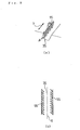
- the four circumferential direction main grooves 3 (3C, 3S) continuous in the tire circumferential direction are provided, in their respective right and left wall surfaces, with a large number of fine grooves 5 (5C, 5S) being inclined to the tire circumferential direction at an angle of ⁇ as shown in Fig. 2A to Fig 3B .
- the shape of the fine grooves 5 is preferably practically a straight line, but may be slightly curved or crooked.
- the fine grooves 5S provided at right and left wall surfaces of each of the two circumferential direction main grooves 3 on the respective right and left shoulder sides are inclined in the same direction in a plan view in a tire radial direction.
- all of the fine grooves 5S are inclined at the same angle in a plan view in the tire radial direction (see Fig. 2B ).
- Reference numeral 6 denotes a center line of the circumferential direction main groove 3.
- the fine grooves 5C provided in a right wall surface and the fine grooves 5C provided in a left wall surface are inclined in directions opposite from each other in a plan view in the tire radial direction.
- the fine grooves 5C in the right wall and the fine grooves 5C in the left wall are formed symmetric with respect to the center line 6 extending in the tire circumferential direction (see Fig. 3B ).
- the plan view in the tire radial direction means "viewing the tread surface from the outside in the tire radial direction.”
- the fine grooves 5S and 5C are provided only in the right and left wall surfaces of the circumferential direction main grooves 3S and 3C, respectively, as shown in Fig. 2A to Fig. 3B .
- the fine grooves 5 in the right wall surface and those in the left wall surface may be extended to the bottom of the circumferential direction main groove 3 so as to communicate with each other.
- the direction in which the fine grooves 5S and 5C are inclined to the tire rotational direction is not limited, and may be inclined to the right or left.
- the right side fine grooves 5C and the left side fine grooves 5C may have respective inclined directions so as to come close to each other as shown in Fig. 3B , or conversely, so as to be far apart from each other, at the downstream side of the tire rotational direction.
- the fine grooves 5 need to be provided in regions along the circumference direction main groove 3, covering 50% or more of the entire circumference thereof in total. If the fine grooves 5 cover less than 50%, desired effects of the present invention cannot be obtained. Preferably, the fine grooves 5 cover 70% or more, and more preferably, 90% to 100%.
- the fine grooves 5 are provided in the two walls of each circumferential direction main groove 3 in a manner as described above. Specifically, in each of the circumferential direction main grooves 3C on the tire center 2 side, the fine grooves 5C in the right surface and those in the left surface extend in directions opposite to each other and inclined to the tire circumferential direction. The fine grooves 5C are thus line-symmetrically arranged. Thereby, the fine grooves 5C can increase reaction force received from snow or mud. This reaction force received by the fine grooves 5C allows the pneumatic tire of the present invention to exhibit high driving performance.
- the fine grooves 5S all extend in the same direction inclined to the tire circumferential direction.
- the fine grooves 5S allow fluids to flow helically in the main grooves 3S. A rectifying effect is thus produced, which increases draining speed of the water, mud and the like on the running surface. Accordingly, the pneumatic tire exhibits high braking performance.
- the pneumatic tire of the present invention achieves a good balance between the performances on mud and snow as well as the on-road driving stability which would be deteriorated if the lug groove area were increased.
- each fine groove 5 is preferably set to 20° to 70°, more preferably at 35° to 55° in order to effectively produce the effects of the present invention.
- Each of the fine grooves 5 is preferably a straight line in the present invention, but may be slightly curved or crooked.
- the inclined angle ⁇ is defined as an inclined angle of the straight line connecting the two ends of each fine groove 5.
- each fine groove 5 is preferably 0.2 mm to 0.8 mm, more preferably 0.4 mm to 0.6 mm.
- An interval between each two adjacent fine grooves 5 is preferably 0.8 mm to 10 mm, more preferably 1 mm to 5 mm.
- the interval between each two adjacent fine grooves 5 is a distance between side end of one fine groove 5 and side end of the other fine groove 5, measured in the direction orthogonal to the direction of the fine grooves 5.
- the circumferential direction main grooves 3C on the tire center 2 side can exert an increased reaction force against a tire rotation force. Thereby, traction force and braking force of the tire can be increased.
- setting the inclined angle ⁇ within the above range allows the circumferential direction main grooves 3S on the respective shoulder sides to produce an improved rectifying effect in which fluids flow helically. Thereby, the braking performance on wet, snowy and muddy road surface is drastically improved.
- the circumferential direction main grooves 3C on the tire center 2 side can contribute to increased traction performance
- the circumferential direction main grooves 3S on the respective shoulder sides can contribute to increased braking performance.
- a groove width less than 0.2 mm is not preferable since the draining effect by the fine grooves 5 is reduced.
- a groove width larger than 0.8 mm is also not preferable since the improvement in the traction performance is reduced.
- each fine groove 5 in the main grooves 3S on the respective tire shoulder sides is smaller than 0.2 mm or larger than 0.8 mm, the rectifying effect of the fine grooves 5 is reduced, which in turn lowers the draining effect. Therefore, such configuration is not preferable.
- each circumferential direction main groove 3C on the tire center 2 side is preferably located in a way that the center line thereof should be within a region between lines shifted from the tire center 2 respectively by 5% and 15% of the tire contact width on the corresponding side.
- each circumferential direction main groove 3S on the corresponding shoulder side is preferably located in a way that the center line thereof should be within a region between lines shifted from the tire center 2 respectively by 25% and 40% of the tire contact width on the corresponding side.
- the former region is denoted by C
- the latter region is denoted by S.
- a center part of the tread surface largely contributes to driving
- shoulder parts of the tread surface largely contribute to braking. Accordingly, by configuring the circumferential direction main grooves 3 on the tire center 2 side and on the shoulder sides as described above, their respective performance can be exhibited more effectively.
- Each circumferential direction main groove 3C on the tire center 2 side has a groove width of preferably 3% to 7%, more preferably 4% to 6% of the tire contact width.
- each circumferential direction main groove 3S on the corresponding shoulder side has a groove width of preferably 100% to 125%, more preferably 115% to 120% of the groove width of each circumferential direction main groove 3C on the tire center 2 side. If the groove widths of the respective circumferential direction main grooves 3C and 3S are too small, less amount of fluids is affected by the fine grooves 5 (5C, 5S), thereby reducing the expected effects of the present invention.
- each of the main grooves 3S can be improved by setting each of the main grooves 3S to have a large width, such as 115% to 120% of the groove width of each circumferential direction main groove 3C on the tire center 2 side.
- each main circumferential direction main groove 3 are inclined to the normal direction of the tread surface 1 at an inclined angle ⁇ .
- the inclined angle ⁇ is preferably 5° to 13°, more preferably 7° to 10°. If the inclined angle ⁇ of each groove wall to the normal direction of the tread surface 1 is smaller than 5°, block stiffness is reduced, and the effect of the fine grooves 5 is reduced. Meanwhile, if the inclined angle ⁇ is larger than 13°, the above rectifying effect is reduced.
- the pneumatic tire of the present invention preferably employs a tread surface with a groove area ratio (%) within a certain range which is generally applied to mud and snow tires.
- the groove area ratio is set to 30% to 50%.
- the groove area ratio of lug grooves 8 should especially be set to 5% to 20%.
- the "groove area ratio of the tread surface (%)” is a proportion of an area which is actually not in contact with the ground to the contact area in the contact surface.
- the "groove area ratio of lug grooves (%)” is a proportion of a total area of the lug grooves 8 to an area of each of the land portions 4 defined by the circumferential direction main grooves 3 (including lug groove portions).
- the groove area ratio of lug grooves is obtained by excluding the total area of the circumferential direction main grooves 3 in the above groove area ratio of the tread surface.
- the tire contact width mentioned in the present invention is a contact width measured in a tire axial direction when the tire is inflated to an air pressure, and then applied a load of 80% of the maximum load capacity of the tire.
- the air pressure applied here is selected from the air pressure-load capacity correspondence table specified by JATMA, as one that corresponds to the maximum load capacity of the tire.
- the contact surface is a region surrounded by the contacting outer edges when the tire is applied the above described load.
- Each of the eight types of tires was fitted onto a rim with size of 17x8J (measuring rim) and inflated to an air pressure of 200 kPa. Then, the tire was mounted on a four-wheel-drive RV wagon, and running tests described below were performed on the tire running on the test course.
- Table 1 and Table 2 show the results of the tests.
- the pneumatic tires of the present invention showed excellent braking and driving performance in running under wet and snowy condition.
- the tires showed excellent on-road driving stability performance, which cannot be observed in conventional pneumatic tires designed for the same purpose.
- a braking distance from an initial speed of 100 km/h was measured for each tire on the wet test course.
- the braking distances are indicated by indices where the distance of Conventional Example is normalized to 100. The larger the index is, the more excellent the tire is in wet braking ability.
- a braking distance from an initial speed of 40 km/h was measured for each tire on the snowy test course.
- the braking distances are indicated by indices where the distance of Conventional Example is normalized to 100. The larger the index is, the more excellent the tire is in braking ability on snow.
- a frictional coefficient between the tire and the road surface at speed of 5 km/h was measured for each tire on the snowy test course.
- the frictional coefficients are indicated by indices where the frictional coefficient of Conventional Example is normalized to 100. The larger the index is, the more excellent the tire is in driving ability on snow. (4) On-Road Driving Stability
Landscapes
- Engineering & Computer Science (AREA)
- Mechanical Engineering (AREA)
- Tires In General (AREA)
- Medicines Containing Material From Animals Or Micro-Organisms (AREA)
Applications Claiming Priority (1)
| Application Number | Priority Date | Filing Date | Title |
|---|---|---|---|
| JP2008144277 | 2008-06-02 |
Publications (2)
| Publication Number | Publication Date |
|---|---|
| EP2130692A1 true EP2130692A1 (de) | 2009-12-09 |
| EP2130692B1 EP2130692B1 (de) | 2010-11-10 |
Family
ID=40996754
Family Applications (1)
| Application Number | Title | Priority Date | Filing Date |
|---|---|---|---|
| EP09007049A Active EP2130692B1 (de) | 2008-06-02 | 2009-05-27 | Luftreifen |
Country Status (6)
| Country | Link |
|---|---|
| US (1) | US8596318B2 (de) |
| EP (1) | EP2130692B1 (de) |
| JP (1) | JP5278127B2 (de) |
| CN (1) | CN101596844B (de) |
| AT (1) | ATE487615T1 (de) |
| DE (1) | DE602009000334D1 (de) |
Cited By (5)
| Publication number | Priority date | Publication date | Assignee | Title |
|---|---|---|---|---|
| US20120273105A1 (en) * | 2009-09-22 | 2012-11-01 | Bridgestone Corporation | Winter tyre with improved traction on snow surfaces |
| EP3047980A4 (de) * | 2013-09-17 | 2017-05-10 | The Yokohama Rubber Company, Limited | Luftreifen |
| WO2017092899A1 (de) * | 2015-12-04 | 2017-06-08 | Continental Reifen Deutschland Gmbh | Fahrzeugluftreifen |
| EP2583839A3 (de) * | 2011-10-20 | 2017-11-15 | Sumitomo Rubber Industries, Ltd. | Schwerlastreifen |
| CN110352136A (zh) * | 2017-03-02 | 2019-10-18 | 株式会社普利司通 | 轮胎 |
Families Citing this family (17)
| Publication number | Priority date | Publication date | Assignee | Title |
|---|---|---|---|---|
| JP4471031B1 (ja) * | 2009-02-16 | 2010-06-02 | 横浜ゴム株式会社 | 空気入りタイヤ |
| JP5062344B1 (ja) * | 2011-04-12 | 2012-10-31 | 横浜ゴム株式会社 | 空気入りタイヤ |
| WO2013015410A1 (ja) * | 2011-07-27 | 2013-01-31 | 株式会社ブリヂストン | タイヤ |
| JP5895778B2 (ja) * | 2012-09-06 | 2016-03-30 | 横浜ゴム株式会社 | 空気入りタイヤ |
| RU2599856C1 (ru) * | 2013-03-06 | 2016-10-20 | Дзе Йокогама Раббер Ко., Лтд. | Пневматическая шина |
| US9259975B2 (en) * | 2013-03-15 | 2016-02-16 | The Goodyear Tire & Rubber Company | Tire with outer groove containing bonded tube |
| US20140360641A1 (en) * | 2013-06-05 | 2014-12-11 | Cooper Tire & Rubber Company | Tire tread with angled rib groove walls |
| EP2860048B1 (de) * | 2013-10-09 | 2018-06-20 | Cooper Tire & Rubber Company | Reifenlauffläche mit geneigten und gerippten Nutenwänden |
| CN105764708B (zh) * | 2013-12-20 | 2018-05-25 | 住友橡胶工业株式会社 | 冬用轮胎 |
| JP6010576B2 (ja) * | 2014-04-14 | 2016-10-19 | 住友ゴム工業株式会社 | 空気入りタイヤ |
| JP2017530050A (ja) | 2014-10-06 | 2017-10-12 | ブリヂストン アメリカズ タイヤ オペレーションズ、 エルエルシー | タイヤトラクション要素 |
| JP6851858B2 (ja) * | 2017-03-02 | 2021-03-31 | 株式会社ブリヂストン | タイヤ |
| JP7375441B2 (ja) | 2019-10-08 | 2023-11-08 | 住友ゴム工業株式会社 | タイヤ |
| JP7375442B2 (ja) | 2019-10-08 | 2023-11-08 | 住友ゴム工業株式会社 | タイヤ |
| JP7375443B2 (ja) | 2019-10-08 | 2023-11-08 | 住友ゴム工業株式会社 | タイヤ |
| JP2022122121A (ja) * | 2021-02-09 | 2022-08-22 | 住友ゴム工業株式会社 | タイヤ |
| DE102021211651A1 (de) * | 2021-10-15 | 2023-04-20 | Continental Reifen Deutschland Gmbh | Fahrzeugluftreifen |
Citations (5)
| Publication number | Priority date | Publication date | Assignee | Title |
|---|---|---|---|---|
| US2268344A (en) * | 1938-08-18 | 1941-12-30 | Us Rubber Co | Pneumatic tire tread |
| JPH04201606A (ja) * | 1990-11-30 | 1992-07-22 | Yokohama Rubber Co Ltd:The | 空気入りタイヤ |
| EP1568514A1 (de) * | 2002-11-26 | 2005-08-31 | The Yokohama Rubber Co., Ltd. | Luftreifen |
| JP2006069305A (ja) * | 2004-08-31 | 2006-03-16 | Sumitomo Rubber Ind Ltd | 空気入りタイヤ |
| JP2006137239A (ja) | 2004-11-10 | 2006-06-01 | Bridgestone Corp | 空気入りタイヤ |
Family Cites Families (28)
| Publication number | Priority date | Publication date | Assignee | Title |
|---|---|---|---|---|
| NL133932C (de) * | 1967-09-18 | |||
| FR2461602A1 (fr) * | 1979-07-24 | 1981-02-06 | Michelin & Cie | Pneumatique destine a rouler sur la neige |
| US4449560A (en) * | 1981-05-13 | 1984-05-22 | Bridgestone Tire Company Limited | Heavy duty pneumatic tire |
| JP2800944B2 (ja) * | 1989-10-12 | 1998-09-21 | 住友ゴム工業 株式会社 | 空気入りタイヤ |
| JP2994008B2 (ja) * | 1990-08-16 | 1999-12-27 | 株式会社ブリヂストン | 空気入りラジアルタイヤ |
| JPH05605A (ja) * | 1991-06-25 | 1993-01-08 | Toyo Tire & Rubber Co Ltd | 空気入りラジアルタイヤのトレツド外皮 |
| EP0602989A1 (de) * | 1992-12-16 | 1994-06-22 | Sumitomo Rubber Industries, Co. Ltd | Luftreifen |
| JP2774778B2 (ja) * | 1994-12-16 | 1998-07-09 | 住友ゴム工業株式会社 | 空気入りタイヤ |
| PL186432B1 (pl) * | 1996-12-19 | 2004-01-30 | Michelin Rech Tech | Opona do dużych obciążeń |
| US6196288B1 (en) * | 1997-12-15 | 2001-03-06 | Michelin Recherche Et Technique S.A. | Siping geometry to delay the onset of rib edge wear in truck tires |
| ES2249234T3 (es) * | 1999-07-19 | 2006-04-01 | Bridgestone Corporation | Neumatico. |
| JP3367927B2 (ja) * | 2000-01-24 | 2003-01-20 | 住友ゴム工業株式会社 | 空気入りタイヤ |
| US6866076B2 (en) * | 2000-02-07 | 2005-03-15 | Bridgestone Corporation | Tire having longitudinally extending smaller grooves formed in the walls of a groove |
| US6415835B1 (en) * | 2000-06-08 | 2002-07-09 | The Goodyear Tire & Rubber Company | Pneumatic tire tread having groove with peaks and valleys |
| US6435237B1 (en) * | 2000-06-14 | 2002-08-20 | The Goodyear Tire & Rubber Company | Pneumatic tire having generally rounded footprint shape |
| US7004216B2 (en) * | 2003-12-11 | 2006-02-28 | The Goodyear Tire & Rubber Company | Tire tread including spaced projections in base of groove |
| JP4457735B2 (ja) * | 2004-04-09 | 2010-04-28 | 横浜ゴム株式会社 | 空気入りタイヤ |
| JP4299745B2 (ja) * | 2004-08-12 | 2009-07-22 | 住友ゴム工業株式会社 | 空気入りタイヤ |
| JP4312141B2 (ja) * | 2004-10-13 | 2009-08-12 | 住友ゴム工業株式会社 | 重荷重用ラジアルタイヤ |
| JP2006151314A (ja) * | 2004-12-01 | 2006-06-15 | Bridgestone Corp | 空気入りタイヤ |
| JP4604861B2 (ja) * | 2005-06-10 | 2011-01-05 | 横浜ゴム株式会社 | 空気入りタイヤ |
| JP4661421B2 (ja) * | 2005-07-15 | 2011-03-30 | 横浜ゴム株式会社 | 空気入りタイヤ |
| CN101341035B (zh) * | 2005-12-20 | 2010-07-28 | 住友橡胶工业株式会社 | 重载荷用轮胎 |
| JP4950491B2 (ja) * | 2005-12-29 | 2012-06-13 | 住友ゴム工業株式会社 | 重荷重用タイヤ |
| JP4921889B2 (ja) * | 2006-08-23 | 2012-04-25 | 住友ゴム工業株式会社 | 空気入りタイヤ |
| JP5129470B2 (ja) * | 2006-08-24 | 2013-01-30 | 住友ゴム工業株式会社 | 空気入りタイヤ |
| JP4968895B2 (ja) * | 2006-09-25 | 2012-07-04 | 東洋ゴム工業株式会社 | 悪路走行用空気入りタイヤ |
| JP5032829B2 (ja) * | 2006-11-13 | 2012-09-26 | 住友ゴム工業株式会社 | 空気入りタイヤ |
-
2009
- 2009-04-13 JP JP2009097024A patent/JP5278127B2/ja not_active Expired - Fee Related
- 2009-05-14 US US12/466,146 patent/US8596318B2/en active Active
- 2009-05-27 EP EP09007049A patent/EP2130692B1/de active Active
- 2009-05-27 DE DE602009000334T patent/DE602009000334D1/de active Active
- 2009-05-27 AT AT09007049T patent/ATE487615T1/de not_active IP Right Cessation
- 2009-06-02 CN CN200910142728.7A patent/CN101596844B/zh active Active
Patent Citations (5)
| Publication number | Priority date | Publication date | Assignee | Title |
|---|---|---|---|---|
| US2268344A (en) * | 1938-08-18 | 1941-12-30 | Us Rubber Co | Pneumatic tire tread |
| JPH04201606A (ja) * | 1990-11-30 | 1992-07-22 | Yokohama Rubber Co Ltd:The | 空気入りタイヤ |
| EP1568514A1 (de) * | 2002-11-26 | 2005-08-31 | The Yokohama Rubber Co., Ltd. | Luftreifen |
| JP2006069305A (ja) * | 2004-08-31 | 2006-03-16 | Sumitomo Rubber Ind Ltd | 空気入りタイヤ |
| JP2006137239A (ja) | 2004-11-10 | 2006-06-01 | Bridgestone Corp | 空気入りタイヤ |
Cited By (13)
| Publication number | Priority date | Publication date | Assignee | Title |
|---|---|---|---|---|
| US20120273105A1 (en) * | 2009-09-22 | 2012-11-01 | Bridgestone Corporation | Winter tyre with improved traction on snow surfaces |
| US20150224827A1 (en) * | 2009-09-22 | 2015-08-13 | Bridgestone Corporation | Winter tyre with improved traction on snow surfaces |
| US9211765B2 (en) * | 2009-09-22 | 2015-12-15 | Bridgestone Corporation | Winter tyre with improved traction on snow surfaces |
| US9358841B2 (en) * | 2009-09-22 | 2016-06-07 | Bridgestone Corporation | Winter tyre with improved traction on snow surfaces |
| EP2583839A3 (de) * | 2011-10-20 | 2017-11-15 | Sumitomo Rubber Industries, Ltd. | Schwerlastreifen |
| EP3047980A4 (de) * | 2013-09-17 | 2017-05-10 | The Yokohama Rubber Company, Limited | Luftreifen |
| US10576789B2 (en) | 2013-09-17 | 2020-03-03 | The Yokohama Rubber Co., Ltd. | Pneumatic tire |
| WO2017092899A1 (de) * | 2015-12-04 | 2017-06-08 | Continental Reifen Deutschland Gmbh | Fahrzeugluftreifen |
| CN108367622A (zh) * | 2015-12-04 | 2018-08-03 | 大陆轮胎德国有限公司 | 车辆充气轮胎 |
| CN110352136A (zh) * | 2017-03-02 | 2019-10-18 | 株式会社普利司通 | 轮胎 |
| EP3590732A4 (de) * | 2017-03-02 | 2020-01-08 | Bridgestone Corporation | Reifen |
| CN110352136B (zh) * | 2017-03-02 | 2022-04-01 | 株式会社普利司通 | 轮胎 |
| US11511568B2 (en) | 2017-03-02 | 2022-11-29 | Bridgestone Corporation | Tire |
Also Published As
| Publication number | Publication date |
|---|---|
| ATE487615T1 (de) | 2010-11-15 |
| CN101596844B (zh) | 2011-12-14 |
| CN101596844A (zh) | 2009-12-09 |
| US20090294003A1 (en) | 2009-12-03 |
| JP5278127B2 (ja) | 2013-09-04 |
| EP2130692B1 (de) | 2010-11-10 |
| DE602009000334D1 (de) | 2010-12-23 |
| JP2010013091A (ja) | 2010-01-21 |
| US8596318B2 (en) | 2013-12-03 |
Similar Documents
| Publication | Publication Date | Title |
|---|---|---|
| EP2130692B1 (de) | Luftreifen | |
| EP2108531B1 (de) | Pneumatischer Reifen | |
| EP3351407B1 (de) | Reifen | |
| EP2163405B1 (de) | Luftreifen | |
| EP3308980B1 (de) | Reifen | |
| KR100915110B1 (ko) | 공기 타이어 | |
| KR101788883B1 (ko) | 공기 타이어 | |
| US8517069B2 (en) | Pneumatic tire with tread having sipes, circumferential main grooves and lateral grooves | |
| KR101824569B1 (ko) | 공기입 타이어 | |
| EP2230100B1 (de) | Luftreifen | |
| EP3025875A1 (de) | Luftreifen | |
| EP2070730B1 (de) | Luftreifen | |
| EP2620299A1 (de) | Luftreifen | |
| EP2732981A2 (de) | Luftreifen | |
| EP1498288A1 (de) | Luftreifen | |
| CN101835634A (zh) | 充气轮胎 | |
| EP3693187B1 (de) | Reifen | |
| KR101066806B1 (ko) | 공기 타이어 | |
| US6935392B2 (en) | Pneumatic tire including slant main grooves and sipes | |
| WO2000006398A1 (fr) | Pneumatique | |
| JP5168803B2 (ja) | 空気入りタイヤ | |
| US11400764B2 (en) | Tire | |
| EP3517322B1 (de) | Reifen | |
| US11505006B2 (en) | Tyre | |
| EP3936351A1 (de) | Luftreifen |
Legal Events
| Date | Code | Title | Description |
|---|---|---|---|
| PUAI | Public reference made under article 153(3) epc to a published international application that has entered the european phase |
Free format text: ORIGINAL CODE: 0009012 |
|
| AK | Designated contracting states |
Kind code of ref document: A1 Designated state(s): AT BE BG CH CY CZ DE DK EE ES FI FR GB GR HR HU IE IS IT LI LT LU LV MC MK MT NL NO PL PT RO SE SI SK TR |
|
| 17P | Request for examination filed |
Effective date: 20100128 |
|
| GRAP | Despatch of communication of intention to grant a patent |
Free format text: ORIGINAL CODE: EPIDOSNIGR1 |
|
| GRAS | Grant fee paid |
Free format text: ORIGINAL CODE: EPIDOSNIGR3 |
|
| RIN1 | Information on inventor provided before grant (corrected) |
Inventor name: HORIUCHI, KENJI,C/O THE YOKOHAMA RUBBER CO., LTD. |
|
| GRAA | (expected) grant |
Free format text: ORIGINAL CODE: 0009210 |
|
| AK | Designated contracting states |
Kind code of ref document: B1 Designated state(s): AT BE BG CH CY CZ DE DK EE ES FI FR GB GR HR HU IE IS IT LI LT LU LV MC MK MT NL NO PL PT RO SE SI SK TR |
|
| REG | Reference to a national code |
Ref country code: GB Ref legal event code: FG4D |
|
| REG | Reference to a national code |
Ref country code: CH Ref legal event code: EP |
|
| RIN2 | Information on inventor provided after grant (corrected) |
Inventor name: HORIUCHI, KENJI,C/O THE YOKOHAMA RUBBER CO., LTD. |
|
| REG | Reference to a national code |
Ref country code: IE Ref legal event code: FG4D |
|
| REF | Corresponds to: |
Ref document number: 602009000334 Country of ref document: DE Date of ref document: 20101223 Kind code of ref document: P |
|
| REG | Reference to a national code |
Ref country code: NL Ref legal event code: VDEP Effective date: 20101110 |
|
| LTIE | Lt: invalidation of european patent or patent extension |
Effective date: 20101110 |
|
| PG25 | Lapsed in a contracting state [announced via postgrant information from national office to epo] |
Ref country code: LT Free format text: LAPSE BECAUSE OF FAILURE TO SUBMIT A TRANSLATION OF THE DESCRIPTION OR TO PAY THE FEE WITHIN THE PRESCRIBED TIME-LIMIT Effective date: 20101110 Ref country code: NO Free format text: LAPSE BECAUSE OF FAILURE TO SUBMIT A TRANSLATION OF THE DESCRIPTION OR TO PAY THE FEE WITHIN THE PRESCRIBED TIME-LIMIT Effective date: 20110210 |
|
| PG25 | Lapsed in a contracting state [announced via postgrant information from national office to epo] |
Ref country code: SI Free format text: LAPSE BECAUSE OF FAILURE TO SUBMIT A TRANSLATION OF THE DESCRIPTION OR TO PAY THE FEE WITHIN THE PRESCRIBED TIME-LIMIT Effective date: 20101110 Ref country code: HR Free format text: LAPSE BECAUSE OF FAILURE TO SUBMIT A TRANSLATION OF THE DESCRIPTION OR TO PAY THE FEE WITHIN THE PRESCRIBED TIME-LIMIT Effective date: 20101110 Ref country code: CY Free format text: LAPSE BECAUSE OF FAILURE TO SUBMIT A TRANSLATION OF THE DESCRIPTION OR TO PAY THE FEE WITHIN THE PRESCRIBED TIME-LIMIT Effective date: 20101110 Ref country code: FI Free format text: LAPSE BECAUSE OF FAILURE TO SUBMIT A TRANSLATION OF THE DESCRIPTION OR TO PAY THE FEE WITHIN THE PRESCRIBED TIME-LIMIT Effective date: 20101110 Ref country code: AT Free format text: LAPSE BECAUSE OF FAILURE TO SUBMIT A TRANSLATION OF THE DESCRIPTION OR TO PAY THE FEE WITHIN THE PRESCRIBED TIME-LIMIT Effective date: 20101110 Ref country code: SE Free format text: LAPSE BECAUSE OF FAILURE TO SUBMIT A TRANSLATION OF THE DESCRIPTION OR TO PAY THE FEE WITHIN THE PRESCRIBED TIME-LIMIT Effective date: 20101110 Ref country code: BG Free format text: LAPSE BECAUSE OF FAILURE TO SUBMIT A TRANSLATION OF THE DESCRIPTION OR TO PAY THE FEE WITHIN THE PRESCRIBED TIME-LIMIT Effective date: 20110210 Ref country code: LV Free format text: LAPSE BECAUSE OF FAILURE TO SUBMIT A TRANSLATION OF THE DESCRIPTION OR TO PAY THE FEE WITHIN THE PRESCRIBED TIME-LIMIT Effective date: 20101110 Ref country code: IS Free format text: LAPSE BECAUSE OF FAILURE TO SUBMIT A TRANSLATION OF THE DESCRIPTION OR TO PAY THE FEE WITHIN THE PRESCRIBED TIME-LIMIT Effective date: 20110310 Ref country code: NL Free format text: LAPSE BECAUSE OF FAILURE TO SUBMIT A TRANSLATION OF THE DESCRIPTION OR TO PAY THE FEE WITHIN THE PRESCRIBED TIME-LIMIT Effective date: 20101110 Ref country code: PT Free format text: LAPSE BECAUSE OF FAILURE TO SUBMIT A TRANSLATION OF THE DESCRIPTION OR TO PAY THE FEE WITHIN THE PRESCRIBED TIME-LIMIT Effective date: 20110310 |
|
| PG25 | Lapsed in a contracting state [announced via postgrant information from national office to epo] |
Ref country code: GR Free format text: LAPSE BECAUSE OF FAILURE TO SUBMIT A TRANSLATION OF THE DESCRIPTION OR TO PAY THE FEE WITHIN THE PRESCRIBED TIME-LIMIT Effective date: 20110211 |
|
| PG25 | Lapsed in a contracting state [announced via postgrant information from national office to epo] |
Ref country code: ES Free format text: LAPSE BECAUSE OF FAILURE TO SUBMIT A TRANSLATION OF THE DESCRIPTION OR TO PAY THE FEE WITHIN THE PRESCRIBED TIME-LIMIT Effective date: 20110221 Ref country code: BE Free format text: LAPSE BECAUSE OF FAILURE TO SUBMIT A TRANSLATION OF THE DESCRIPTION OR TO PAY THE FEE WITHIN THE PRESCRIBED TIME-LIMIT Effective date: 20101110 Ref country code: CZ Free format text: LAPSE BECAUSE OF FAILURE TO SUBMIT A TRANSLATION OF THE DESCRIPTION OR TO PAY THE FEE WITHIN THE PRESCRIBED TIME-LIMIT Effective date: 20101110 Ref country code: EE Free format text: LAPSE BECAUSE OF FAILURE TO SUBMIT A TRANSLATION OF THE DESCRIPTION OR TO PAY THE FEE WITHIN THE PRESCRIBED TIME-LIMIT Effective date: 20101110 |
|
| PG25 | Lapsed in a contracting state [announced via postgrant information from national office to epo] |
Ref country code: RO Free format text: LAPSE BECAUSE OF FAILURE TO SUBMIT A TRANSLATION OF THE DESCRIPTION OR TO PAY THE FEE WITHIN THE PRESCRIBED TIME-LIMIT Effective date: 20101110 Ref country code: SK Free format text: LAPSE BECAUSE OF FAILURE TO SUBMIT A TRANSLATION OF THE DESCRIPTION OR TO PAY THE FEE WITHIN THE PRESCRIBED TIME-LIMIT Effective date: 20101110 Ref country code: PL Free format text: LAPSE BECAUSE OF FAILURE TO SUBMIT A TRANSLATION OF THE DESCRIPTION OR TO PAY THE FEE WITHIN THE PRESCRIBED TIME-LIMIT Effective date: 20101110 Ref country code: DK Free format text: LAPSE BECAUSE OF FAILURE TO SUBMIT A TRANSLATION OF THE DESCRIPTION OR TO PAY THE FEE WITHIN THE PRESCRIBED TIME-LIMIT Effective date: 20101110 |
|
| PLBE | No opposition filed within time limit |
Free format text: ORIGINAL CODE: 0009261 |
|
| STAA | Information on the status of an ep patent application or granted ep patent |
Free format text: STATUS: NO OPPOSITION FILED WITHIN TIME LIMIT |
|
| 26N | No opposition filed |
Effective date: 20110811 |
|
| REG | Reference to a national code |
Ref country code: DE Ref legal event code: R097 Ref document number: 602009000334 Country of ref document: DE Effective date: 20110811 |
|
| PG25 | Lapsed in a contracting state [announced via postgrant information from national office to epo] |
Ref country code: MT Free format text: LAPSE BECAUSE OF FAILURE TO SUBMIT A TRANSLATION OF THE DESCRIPTION OR TO PAY THE FEE WITHIN THE PRESCRIBED TIME-LIMIT Effective date: 20101110 Ref country code: IT Free format text: LAPSE BECAUSE OF FAILURE TO SUBMIT A TRANSLATION OF THE DESCRIPTION OR TO PAY THE FEE WITHIN THE PRESCRIBED TIME-LIMIT Effective date: 20101110 Ref country code: MC Free format text: LAPSE BECAUSE OF NON-PAYMENT OF DUE FEES Effective date: 20110531 |
|
| REG | Reference to a national code |
Ref country code: FR Ref legal event code: ST Effective date: 20120131 |
|
| REG | Reference to a national code |
Ref country code: IE Ref legal event code: MM4A |
|
| PG25 | Lapsed in a contracting state [announced via postgrant information from national office to epo] |
Ref country code: FR Free format text: LAPSE BECAUSE OF NON-PAYMENT OF DUE FEES Effective date: 20110531 Ref country code: IE Free format text: LAPSE BECAUSE OF NON-PAYMENT OF DUE FEES Effective date: 20110527 |
|
| PG25 | Lapsed in a contracting state [announced via postgrant information from national office to epo] |
Ref country code: MK Free format text: LAPSE BECAUSE OF FAILURE TO SUBMIT A TRANSLATION OF THE DESCRIPTION OR TO PAY THE FEE WITHIN THE PRESCRIBED TIME-LIMIT Effective date: 20101110 |
|
| PG25 | Lapsed in a contracting state [announced via postgrant information from national office to epo] |
Ref country code: LU Free format text: LAPSE BECAUSE OF NON-PAYMENT OF DUE FEES Effective date: 20110527 |
|
| PG25 | Lapsed in a contracting state [announced via postgrant information from national office to epo] |
Ref country code: TR Free format text: LAPSE BECAUSE OF FAILURE TO SUBMIT A TRANSLATION OF THE DESCRIPTION OR TO PAY THE FEE WITHIN THE PRESCRIBED TIME-LIMIT Effective date: 20101110 |
|
| PG25 | Lapsed in a contracting state [announced via postgrant information from national office to epo] |
Ref country code: HU Free format text: LAPSE BECAUSE OF FAILURE TO SUBMIT A TRANSLATION OF THE DESCRIPTION OR TO PAY THE FEE WITHIN THE PRESCRIBED TIME-LIMIT Effective date: 20101110 |
|
| REG | Reference to a national code |
Ref country code: CH Ref legal event code: PL |
|
| GBPC | Gb: european patent ceased through non-payment of renewal fee |
Effective date: 20130527 |
|
| PG25 | Lapsed in a contracting state [announced via postgrant information from national office to epo] |
Ref country code: CH Free format text: LAPSE BECAUSE OF NON-PAYMENT OF DUE FEES Effective date: 20130531 Ref country code: LI Free format text: LAPSE BECAUSE OF NON-PAYMENT OF DUE FEES Effective date: 20130531 |
|
| PG25 | Lapsed in a contracting state [announced via postgrant information from national office to epo] |
Ref country code: GB Free format text: LAPSE BECAUSE OF NON-PAYMENT OF DUE FEES Effective date: 20130527 |
|
| P01 | Opt-out of the competence of the unified patent court (upc) registered |
Effective date: 20230512 |
|
| PGFP | Annual fee paid to national office [announced via postgrant information from national office to epo] |
Ref country code: DE Payment date: 20230404 Year of fee payment: 15 |