EP3025875A1 - Luftreifen - Google Patents
Luftreifen Download PDFInfo
- Publication number
- EP3025875A1 EP3025875A1 EP15195272.8A EP15195272A EP3025875A1 EP 3025875 A1 EP3025875 A1 EP 3025875A1 EP 15195272 A EP15195272 A EP 15195272A EP 3025875 A1 EP3025875 A1 EP 3025875A1
- Authority
- EP
- European Patent Office
- Prior art keywords
- groove
- shoulder
- center
- land section
- main groove
- Prior art date
- Legal status (The legal status is an assumption and is not a legal conclusion. Google has not performed a legal analysis and makes no representation as to the accuracy of the status listed.)
- Granted
Links
- 230000007704 transition Effects 0.000 claims description 12
- 238000012360 testing method Methods 0.000 description 12
- XLYOFNOQVPJJNP-UHFFFAOYSA-N water Substances O XLYOFNOQVPJJNP-UHFFFAOYSA-N 0.000 description 7
- 230000000052 comparative effect Effects 0.000 description 6
- 230000004044 response Effects 0.000 description 5
- 230000004323 axial length Effects 0.000 description 4
- 230000002708 enhancing effect Effects 0.000 description 4
- 230000004043 responsiveness Effects 0.000 description 4
- 230000000694 effects Effects 0.000 description 3
- 230000001105 regulatory effect Effects 0.000 description 3
- 230000001052 transient effect Effects 0.000 description 3
- 230000001133 acceleration Effects 0.000 description 1
- 239000010426 asphalt Substances 0.000 description 1
- 238000013461 design Methods 0.000 description 1
- 238000007599 discharging Methods 0.000 description 1
- 238000006073 displacement reaction Methods 0.000 description 1
- 238000011156 evaluation Methods 0.000 description 1
- 238000005259 measurement Methods 0.000 description 1
- 238000012986 modification Methods 0.000 description 1
- 230000004048 modification Effects 0.000 description 1
- 230000002035 prolonged effect Effects 0.000 description 1
- 230000001953 sensory effect Effects 0.000 description 1
- 238000010998 test method Methods 0.000 description 1
Images


Classifications
-
- B—PERFORMING OPERATIONS; TRANSPORTING
- B60—VEHICLES IN GENERAL
- B60C—VEHICLE TYRES; TYRE INFLATION; TYRE CHANGING; CONNECTING VALVES TO INFLATABLE ELASTIC BODIES IN GENERAL; DEVICES OR ARRANGEMENTS RELATED TO TYRES
- B60C11/00—Tyre tread bands; Tread patterns; Anti-skid inserts
- B60C11/03—Tread patterns
- B60C11/032—Patterns comprising isolated recesses
-
- B—PERFORMING OPERATIONS; TRANSPORTING
- B60—VEHICLES IN GENERAL
- B60C—VEHICLE TYRES; TYRE INFLATION; TYRE CHANGING; CONNECTING VALVES TO INFLATABLE ELASTIC BODIES IN GENERAL; DEVICES OR ARRANGEMENTS RELATED TO TYRES
- B60C11/00—Tyre tread bands; Tread patterns; Anti-skid inserts
- B60C11/03—Tread patterns
- B60C11/0327—Tread patterns characterised by special properties of the tread pattern
- B60C11/0332—Tread patterns characterised by special properties of the tread pattern by the footprint-ground contacting area of the tyre tread
-
- B—PERFORMING OPERATIONS; TRANSPORTING
- B60—VEHICLES IN GENERAL
- B60C—VEHICLE TYRES; TYRE INFLATION; TYRE CHANGING; CONNECTING VALVES TO INFLATABLE ELASTIC BODIES IN GENERAL; DEVICES OR ARRANGEMENTS RELATED TO TYRES
- B60C11/00—Tyre tread bands; Tread patterns; Anti-skid inserts
- B60C11/03—Tread patterns
- B60C11/0302—Tread patterns directional pattern, i.e. with main rolling direction
-
- B—PERFORMING OPERATIONS; TRANSPORTING
- B60—VEHICLES IN GENERAL
- B60C—VEHICLE TYRES; TYRE INFLATION; TYRE CHANGING; CONNECTING VALVES TO INFLATABLE ELASTIC BODIES IN GENERAL; DEVICES OR ARRANGEMENTS RELATED TO TYRES
- B60C11/00—Tyre tread bands; Tread patterns; Anti-skid inserts
- B60C11/03—Tread patterns
- B60C11/0304—Asymmetric patterns
-
- B—PERFORMING OPERATIONS; TRANSPORTING
- B60—VEHICLES IN GENERAL
- B60C—VEHICLE TYRES; TYRE INFLATION; TYRE CHANGING; CONNECTING VALVES TO INFLATABLE ELASTIC BODIES IN GENERAL; DEVICES OR ARRANGEMENTS RELATED TO TYRES
- B60C11/00—Tyre tread bands; Tread patterns; Anti-skid inserts
- B60C11/03—Tread patterns
- B60C11/0318—Tread patterns irregular patterns with particular pitch sequence
-
- B—PERFORMING OPERATIONS; TRANSPORTING
- B60—VEHICLES IN GENERAL
- B60C—VEHICLE TYRES; TYRE INFLATION; TYRE CHANGING; CONNECTING VALVES TO INFLATABLE ELASTIC BODIES IN GENERAL; DEVICES OR ARRANGEMENTS RELATED TO TYRES
- B60C11/00—Tyre tread bands; Tread patterns; Anti-skid inserts
- B60C11/03—Tread patterns
- B60C2011/0337—Tread patterns characterised by particular design features of the pattern
- B60C2011/0339—Grooves
- B60C2011/0341—Circumferential grooves
-
- B—PERFORMING OPERATIONS; TRANSPORTING
- B60—VEHICLES IN GENERAL
- B60C—VEHICLE TYRES; TYRE INFLATION; TYRE CHANGING; CONNECTING VALVES TO INFLATABLE ELASTIC BODIES IN GENERAL; DEVICES OR ARRANGEMENTS RELATED TO TYRES
- B60C11/00—Tyre tread bands; Tread patterns; Anti-skid inserts
- B60C11/03—Tread patterns
- B60C2011/0337—Tread patterns characterised by particular design features of the pattern
- B60C2011/0339—Grooves
- B60C2011/0358—Lateral grooves, i.e. having an angle of 45 to 90 degees to the equatorial plane
- B60C2011/0367—Lateral grooves, i.e. having an angle of 45 to 90 degees to the equatorial plane characterised by depth
-
- B—PERFORMING OPERATIONS; TRANSPORTING
- B60—VEHICLES IN GENERAL
- B60C—VEHICLE TYRES; TYRE INFLATION; TYRE CHANGING; CONNECTING VALVES TO INFLATABLE ELASTIC BODIES IN GENERAL; DEVICES OR ARRANGEMENTS RELATED TO TYRES
- B60C11/00—Tyre tread bands; Tread patterns; Anti-skid inserts
- B60C11/03—Tread patterns
- B60C2011/0337—Tread patterns characterised by particular design features of the pattern
- B60C2011/0339—Grooves
- B60C2011/0374—Slant grooves, i.e. having an angle of about 5 to 35 degrees to the equatorial plane
-
- B—PERFORMING OPERATIONS; TRANSPORTING
- B60—VEHICLES IN GENERAL
- B60C—VEHICLE TYRES; TYRE INFLATION; TYRE CHANGING; CONNECTING VALVES TO INFLATABLE ELASTIC BODIES IN GENERAL; DEVICES OR ARRANGEMENTS RELATED TO TYRES
- B60C11/00—Tyre tread bands; Tread patterns; Anti-skid inserts
- B60C11/03—Tread patterns
- B60C2011/0337—Tread patterns characterised by particular design features of the pattern
- B60C2011/0339—Grooves
- B60C2011/0381—Blind or isolated grooves
Definitions
- the present invention relates to a pneumatic tire that exhibits well-balanced enhancement of steering stability and wet performance.
- Patent publication 1 proposes a pneumatic tire with a designated direction to be mounted on a four-wheel vehicle (hereinafter, may also be referred to as simply a "vehicle").
- a pneumatic tire is provided with lateral grooves in the outer and inner middle land sections.
- lateral grooves formed in the inner middle land section are each set to incline in the same direction.
- the inner middle land section having such lateral grooves tends to deform significantly when affected by a force in a direction perpendicular to lateral grooves.
- the degree of deformation when turning right differs from that when turning left.
- the tire deforms significantly. Therefore, the pneumatic tire of patent publication 1 exhibits a low transient response during turning, and steering stability tends to be low as a result.
- Patent Publication 1 JP2013-151236A
- the present invention was carried out in consideration of the above problems. Its main objective is to provide a pneumatic tire that exhibits well-balanced enhancement of steering stability and wet performance.
- An aspect of the present invention is a pneumatic tire having a tread with a designated direction to be mounted on a vehicle.
- the tread includes an inner tread edge to be positioned on the vehicle inner side and an outer tread edge to be positioned on the vehicle outer side when mounted on a vehicle, multiple main grooves extending continuously in a tire circumferential direction so as to form multiple land sections between the tread edges, and multiple lateral grooves extending in a direction to cross the main grooves.
- the main grooves include an inner shoulder-main groove positioned closest to the inner tread edge, an outer shoulder-main groove positioned closest to the outer tread edge, an inner center-main groove positioned between the inner shoulder-main groove and the tire equator, and an outer center-main groove positioned between the outer shoulder-main groove and the tire equator.
- the land sections include an inner middle land section between the inner shoulder-main groove and the inner center-main groove, and an outer middle land section between the outer shoulder-main groove and the outer center-main groove.
- the lateral grooves include inner middle-lateral grooves formed in the inner middle land section, and the outer middle-lateral grooves formed in the outer middle land section.
- the inner middle-lateral grooves include a first inner middle-inclined groove that extends from the inner shoulder-main groove and terminates within the inner middle land section, and a second inner middle-inclined groove that extends from the inner center-main groove and terminates within the inner middle land section while inclining in a direction opposite that of the first inner middle-inclined groove and being arranged alternately with the first inner middle-inclined groove.
- the outer middle-lateral grooves include a first outer middle-inclined groove that extends from the outer shoulder-main groove and terminates within the outer middle land section, and a second outer middle-inclined groove that extends from the outer center-main groove and terminates within the outer middle land section while inclining in a direction opposite that of the first outer middle-inclined groove and being arranged alternately with the first outer middle-inclined groove.
- the total number of the first and second outer middle-inclined grooves is set to be less than the total number of the first and second inner middle-inclined grooves.
- the land sections include a center land section positioned between the inner center-main groove and the outer center-main groove; and that center-lateral grooves formed in the center land section include an inner center-inclined groove that extends from the inner center-main groove and terminates within the center land section, and an outer center-inclined groove that extends from the outer center-main groove and terminates within the center land section.
- the inner center-inclined groove is preferred to make a smooth transition to the second inner middle-inclined groove when connected through the inner center-main groove, while the outer center-inclined groove make a smooth transition to the second outer middle-inclined groove when connected through the outer center-main groove.
- the land sections include an inner shoulder land section positioned on the tire axially outer side of the inner shoulder-main groove, and that inner shoulder-lateral grooves formed in the inner shoulder land section include a first inner shoulder-lateral groove that makes a smooth transition to the first inner middle-inclined groove when connected through the inner shoulder-main groove, and a second inner shoulder-lateral groove that extends from the inner shoulder-main groove in the tire axially outward direction and terminates within the inner shoulder land section.
- the inner shoulder-lateral grooves are each preferred to have a groove width of 7.0 ⁇ 9.0% of the positional pitch and a groove depth of 5.0 ⁇ 7.0 mm.
- the land sections include an outer shoulder land section positioned on the tire axially outer side of the outer shoulder-main groove, and that outer shoulder-lateral grooves formed in the outer shoulder land section include a first outer shoulder-lateral groove that makes a smooth transition to the first outer middle-inclined groove when connected through the outer shoulder-main groove, and a second outer shoulder-lateral groove that extends from the outer tread edge in the tire axially inward direction and terminates within the outer shoulder land section.
- the first outer middle-inclined groove and the second outer middle-inclined groove are preferred to cross the center line that evenly bisects the width of the outer middle land section.
- the first inner middle-inclined groove is preferred to cross the center line that evenly bisects the width of the inner middle land section, whereas the second inner middle-inclined groove is preferred not to cross the center line of the inner middle land section but to terminate before reaching the center line.
- the inner middle-lateral grooves formed in the inner middle land section include first inner middle-inclined grooves that extend from the inner shoulder-main groove and terminate within the inner middle land section, and second inner middle-inclined grooves that extend from the inner center-main groove and terminate within the inner middle land section while inclining in a direction opposite that of the first inner middle-inclined grooves and being arranged alternately with the first inner middle-inclined grooves.
- the outer middle-lateral grooves formed in the outer middle land section include first outer middle-inclined grooves that extend from the outer shoulder-main groove and terminate within the outer middle land section, and second outer middle-inclined grooves that extend from the outer center-main groove and terminate within the outer middle land section while inclining in a direction opposite that of the first outer middle-inclined grooves and being arranged alternately with the first outer middle-inclined grooves.
- middle-lateral grooves are each set to connect to the shoulder-main groove or center-main groove and to terminate within the land section, and thus the rigidity of each middle land section is maintained and excellent wet performance is achieved.
- inclined grooves set to incline in different directions from each other are alternately arranged in a tire circumferential direction. Accordingly, each middle land section deforms linearly in response to the degree of steering during turning without following the direction of a load exerted on the land section. Therefore, a linear transient response is obtained during turning and excellent steering stability is thereby achieved.
- the total number of the first and second outer middle-inclined grooves is set to be less than the total number of the first and second inner middle-inclined grooves.
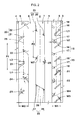
- Fig. 1 is a developed view of tread 2 of pneumatic tire 1 according to the present embodiment.
- pneumatic tire 1 of the present embodiment is a radial tire to be mounted on a passenger car with a designated direction for mounting on a vehicle.
- the direction for mounting on a vehicle is indicated by using letters or symbols on a sidewall (not shown) of pneumatic tire 1.
- the right side is on the vehicle inner side and the left side is on the vehicle outer side when mounted on a vehicle.
- Tread 2 is bordered by inner tread edge (Tei) positioned on the vehicle inner side and outer tread edge (Teo) positioned on the vehicle outer side when the tire is mounted on a vehicle. Between inner tread edge (Tei) and outer tread edge (Teo), multiple main grooves are formed extending continuously in a tire circumferential direction so as to form multiple land sections.
- the main grooves of the present embodiment include inner shoulder-main groove 3 positioned closest to inner tread edge (Tei), outer shoulder-main groove 4 positioned closest to outer tread edge (Teo), inner center-main groove 5 positioned between inner shoulder-main groove 3 and tire equator (C), and outer center-main groove 6 positioned between outer shoulder-main groove 4 and tire equator (C).
- Main grooves 3 ⁇ 6 are each set to extend straight, for example, in a tire circumferential direction. Accordingly, main grooves 3 ⁇ 6 efficiently discharge the water on the ground surface away from the running tire toward the rear of the vehicle. However, the main grooves may also be formed in a zigzag pattern.
- Main grooves 3 ⁇ 6 are each designed to have a certain groove width and groove depth to exhibit excellent drainage capability.
- main grooves 3 ⁇ 6 are set to have a groove width of at least 2.5%, more preferably at least 3%, even more preferably at least 4%, of tread contact-patch width (TW).
- main grooves 3 ⁇ 6 are each set to have a groove width of no greater than 11.5%, more preferably no greater than 10%, even more preferably no greater than 9%, of tread contact-patch width (TW).
- main grooves 3 ⁇ 6 are set to have a groove depth of at least 6 mm, more preferably at least 7 mm, for example.
- Tread contact-patch width indicates the tire axial distance between inner tread edge (Tei) and outer tread edge (Teo) of a tire under normal conditions.
- Normal conditions mean that tire 1 is mounted on a normal rim and is filled with air at a normal inflation pressure while no load is exerted thereon. Unless otherwise specified, measurements of a tire show values obtained when the tire is under normal conditions.
- a "normal rim” indicates a rim specified by a regulatory system that includes standards for each tire: it is specified as a "Normal Rim” by JATMA, "Design Rim” by TRA, and "Measuring Rim” by ETRTO.
- Normal inflation pressure indicates air pressure specified by a regulatory system that includes standards for the tire: it is specified as “Maximum Air Pressure” by JATMA, maximum value listed in the table “Tire Load Limits at Various Cold Inflation Pressures” by TRA, and “Inflation Pressure” by ETRTO.
- the normal inflation pressure is uniformly set at 180 kPa.
- Thread edges are defined as the tire axially outermost points of the tread contact patch when a normal load is exerted on a tire under normal conditions and tread 2 is set on a planar surface with a camber angle of zero degrees.
- Normal load indicates a load specified by a regulatory system that includes standards for the tire: it is specified as “Maximum Load Capacity” by JATMA, maximum value listed in the table “Tire Load Limits at Various Cold Inflation Pressures” by TRA, and “Load Capacity” by ETRTO.
- the normal load is set at 88% of the above load.
- outer shoulder-main groove 4 it is especially preferred for outer shoulder-main groove 4 to have the smallest groove width (GW2) among main grooves.
- GW2 groove width
- Such a structure contributes to improving the land ratio of tread 2 on the vehicle outer side, subsequently to enhancing steering stability.
- GW2 groove width
- tire noise is less likely to leak outside the vehicle, and the tire exhibits excellent quietness during its run.
- groove width (GW3) of inner center-main groove 5 or groove width (GW4) of outer center-main groove 6 be set to be the greatest of the main grooves.
- the width is especially preferred to be at least 7% of tread contact-patch width (TW).
- groove width (GW3) or (GW4) is set two to three times greater than the groove width (GW2) of outer shoulder-main groove 4.
- Tread 2 is divided into five land sections by the aforementioned main grooves 3 ⁇ 6.
- Land sections include center land section 7 between inner center-main groove 5 and outer center-main groove 6, inner middle land section 8 between inner center-main groove 5 and inner shoulder-main groove 3, outer middle land section 9 between outer center-main groove 6 and outer shoulder-main groove 4, inner shoulder land section 10 on the tire axially outer side of inner shoulder-main groove 3, and outer shoulder land section 11 on the tire axially outer side of outer shoulder-main groove 4.
- main grooves 3 ⁇ 6 are respectively arranged in positions so that center land section 7, inner middle land section 8 and outer middle land section 9 have substantially the same width in a tire axial direction.
- the difference in widths of land sections 7 ⁇ 9 is preferred to be within 5 mm.
- inner shoulder land section 10 and outer shoulder land section 11 are set to be wider than any of land sections 7 ⁇ 9. By so setting, the lateral rigidity of inner and outer shoulder land sections (10, 11) is enhanced.
- Tread 2 further includes multiple lateral grooves 12 extending in a direction to cross main grooves 3 ⁇ 6 respectively. The detailed structure of each lateral groove is described later.
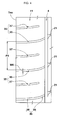
- Fig. 2 is an enlarged view showing inner middle land section 8, outer middle land section 9 and center land section 7 in Fig. 1 .
- inner middle land section 8 is provided with multiple inner middle-lateral grooves 15, which include multiple first inner middle-inclined grooves 16 and multiple second inner middle-inclined grooves 17.
- First inner middle-inclined groove 16 and second inner middle-inclined groove 17 are arranged alternately in a tire circumferential direction.
- Each first inner middle-inclined groove 16 extends from inner shoulder-main groove 3 and terminates within inner middle land section 8.
- Each first inner middle-inclined groove 16 is set to incline relative to a tire axial direction.
- Angle ( ⁇ 1) of first inner middle-inclined groove 16 is, for example, 25 ⁇ 70 degrees, preferably 35 ⁇ 60 degrees, relative to a tire axial direction.
- first inner middle-inclined groove 16 is set to cross center line 18, which evenly bisects the width of inner middle land section 8 and terminates on the tire axially inner side of center line 18.
- Tire axial length (L1) of first inner middle-inclined groove 16 is preferred to be 0.6 ⁇ 0.85 times the tire axial width (W1) of inner middle land section 8.
- Such a structure of first inner middle-inclined groove 16 contributes to enhancing drainage capability effectively while minimizing a decrease in steering stability.
- Second inner middle-inclined groove 17 extends from inner center-main groove 5 and terminates within inner middle land section 8.
- Second inner middle-inclined groove 17 is set to incline in a direction opposite that of first inner middle-inclined groove 16.
- Angle ( ⁇ 2) of second inner middle-inclined groove 17 is, for example, 10 ⁇ 50 degrees, preferably 20 ⁇ 40 degrees, relative to a tire axial direction.
- Second inner middle-inclined groove 17 is preferred not to cross center line 18 of inner middle land section 8 but to terminate before reaching the center line.
- Tire axial length (L2) of second inner middle-inclined groove 17 is preferred to be 0.35 ⁇ 0.50 times the length (L1) of first inner middle-inclined groove 16.
- Such a structure of second inner middle-inclined groove 17 contributes to suppressing uneven wear in the region on the tire axially inner side of inner middle land section 8.
- Groove width (W4) of second inner middle-inclined groove 17 is preferred to be greater than groove width (W3) of first inner middle-inclined groove 16, for example.
- Groove width (W4) of second inner middle-inclined groove 17 is more preferred to be 1.7 ⁇ 2.2 times the groove width (W2) of first inner middle-inclined groove 16, for example.
- Such a structure of second inner middle-inclined groove 17 exhibits excellent wet performance while maintaining the rigidity of inner middle land section 8.
- Outer middle land section 9 is provided with multiple outer middle-lateral grooves 20, which include multiple first outer middle-inclined grooves 21 and multiple second outer middle-inclined grooves 22.
- Each first outer middle-inclined groove 21 extends from outer shoulder-main groove 4 and terminates within outer middle land section 9.
- Each second outer middle-inclined groove 22 extends from outer center-main groove 6 and terminates within outer middle land section 9.
- First outer middle-inclined groove 21 and second outer middle-inclined groove 22 are set to incline in opposite directions and are arranged alternately in a tire circumferential direction.
- inner middle-lateral grooves 15 and outer middle-lateral grooves 20 are connected to shoulder-main grooves (3, 4) or center-main grooves (5, 6), and terminate within the land section. Accordingly, excellent wet performance is achieved while the rigidity of middle land sections (8, 9) is maintained.
- middle land sections (8, 9) are provided with inclined grooves, which are set to incline in different directions from each other and to be positioned alternately in a tire circumferential direction.
- middle land sections (8, 9) deform linearly in response to the degree of steering during turning without following the direction of a load exerted on the land section. Accordingly, linear transient response is achieved during turning, and excellent steering stability is thereby achieved.
- total number (N2) of first and second outer middle-inclined grooves (21, 22) in the tire circumference is set less than total number (N1) of first and second inner middle-inclined grooves (16, 17) in the tire circumference.
- the aforementioned total number (N2) is preferred to be no greater than 0.6 times, more preferably no greater than 0.5 times, the total number (N1). To maintain excellent wet performance, the total number (N2) is preferred to be at least 0.3 times, more preferably at least 0.4 times, the total number (N1).
- first outer middle-inclined groove 21 is set to incline in the same direction as that of first inner middle-inclined groove 16, while second outer middle-inclined groove 22 is set to incline in the same direction as that of second inner middle-inclined groove 17.
- middle land sections (8, 9) wear uniformly.
- angle ( ⁇ 3) of first outer middle-inclined groove 21 relative to the tire axial direction and angle ( ⁇ 4) of second outer middle-inclined groove 22 relative to the tire axial direction are preferred to be, for example, at least 20 degrees, more preferably at least 25 degrees, and to be no greater than 40 degrees, more preferably no greater than 35 degrees.
- First and second outer middle-inclined grooves (21, 22) are each preferred to cross center line 23 evenly bisecting the width of outer middle land section 9.
- Such a structure of first and second outer middle-inclined grooves (21, 22) contributes to effectively discharging water away from between outer middle land section 9 and the ground surface while running on a wet surface, and to suppressing a hydroplaning phenomenon.
- tire axial length (L3) of first outer middle-inclined groove 21 and tire axial length (L4) of second outer middle-inclined groove 22 are preferred to have a total (L3+L4) of 105% ⁇ 115% of width (W2) of outer middle land section 9.
- Center land section 7 is provided with multiple center-lateral grooves 25, which include inner center-inclined grooves 26 that extend from inner center-main groove 5 and terminate within center land section 7 and outer center-inclined grooves 27 that extend from outer center-main groove 6 and terminate within center land section 7. Accordingly, center land section 7 is formed in a rib pattern that extends continuously in a tire circumferential direction.
- Inner center-inclined grooves 26 and outer center-inclined grooves 27 are arranged at positional pitch (P2), which is set to be, for example, 0.95 ⁇ 1.05 times the positional pitch (P1) of outer middle-lateral grooves 20.
- Positional pitch (P2) is preferred to be substantially equal to positional pitch (P1).
- Inner center-inclined grooves 26 and outer center-inclined grooves 27 are set to incline in the same direction relative to a tire axial direction, for example.
- Angle ( ⁇ 5) of inner center-inclined grooves 26 and outer center-inclined grooves 27 is, for example, 25 ⁇ 35 degrees relative to a tire axial direction.
- Angle ( ⁇ 5) is preferred to be substantially equal to angle ( ⁇ 4) of second outer middle-inclined grooves 22, for example.
- Virtually extended line 28 of inner center-inclined groove 26 is preferred to be connected to outer center-inclined groove 27.
- Inner center-inclined groove 26 is preferred to make a smooth transition to second inner middle-inclined groove 17 when connected through inner center-main groove 5.
- outer center-inclined groove 27 is preferred to make a smooth transition to second outer middle-inclined groove 22 when connected through outer center-main groove 6.
- Center-lateral groove 25 is preferred to have groove width (W7) smaller than that of inner middle-lateral groove 15 and outer middle-lateral groove 20, for example.
- Groove width (W7) of center-lateral groove 25 is set to be 0.25 ⁇ 0.35 times the groove width (W4) of second inner middle-inclined groove 17, for example.
- Such a structure of center-lateral groove 25 contributes to maintaining the rigidity of center land section 7 and enhancing steering stability.
- Fig. 3 is an enlarged view showing inner shoulder land section 10 in Fig. 1 .
- inner shoulder land section 10 is provided with multiple inner shoulder-lateral grooves 30, which include first inner shoulder-lateral grooves 31 and second inner shoulder-lateral grooves 32, for example.
- First inner shoulder lateral groove 31 extends from inner shoulder-main groove 3 to inner tread edge (Tei), for example.
- First inner shoulder-lateral groove 31 includes straight component 33, which extends straight along a tire axial direction on the inner tread-edge (Tei) side, and curved component 34, which is connected to straight component 33 and extends in the tire axially inward direction.
- Angle ( ⁇ 6) of curved component 34 relative to a tire axial direction is set to increase gradually toward tire equator (C), for example.
- Such a structure of first inner shoulder-lateral groove 31 contributes to directing some of the water in inner shoulder-main groove 3 in the tire axially outward direction while running on a wet surface so that wet performance is enhanced.
- First inner shoulder-lateral groove 31 of the present embodiment is preferred to make a smooth transition to first inner middle-inclined groove 16 when connected through inner shoulder-main groove 3.
- Such a structure of first inner shoulder-lateral groove 31 directs the water in inner shoulder-main groove 3 toward inner tread edge (Tei) during a wet run by utilizing the inertia of water directed toward inner shoulder-main groove 3 through first inner shoulder-lateral groove 31. Accordingly, even higher drainage capability is achieved.
- Second inner shoulder-lateral groove 32 extends from inner shoulder-main groove 3 in the tire axially outward direction and terminates within inner shoulder land section 10, for example. Such a structure of second inner shoulder-lateral groove 32 contributes to enhancing steering stability while suppressing uneven wear of inner shoulder land section 10.
- Second inner shoulder-lateral groove 32 is preferred to extend along curved component 34 of first inner shoulder lateral groove 31. Such second inner shoulder-lateral groove 32 contributes to the uniform wear of inner shoulder land section 10.
- groove width (W5) of inner shoulder-lateral groove 30 is preferred to be at least 7.0%, more preferably at least 7.5%, and no greater than 9.0%, more preferably no greater than 8.5%, of positional pitch (P3) of inner shoulder-lateral groove 30.
- the groove depth of inner shoulder-lateral groove 30 is preferred to be at least 5.0 mm, more preferably 6.2 mm, and to be no greater than 7.0 mm, more preferably no greater than 6.6 mm.
- Fig. 4 is an enlarged view showing outer shoulder land section 11 in Fig. 1 .
- outer shoulder land section 11 is provided with multiple outer shoulder-lateral grooves 35, which include first outer shoulder-lateral groove 36 and second outer shoulder-lateral groove 37, for example.
- First outer shoulder-lateral groove 36 extends from outer shoulder-main groove 4 to outer tread edge (Teo), for example.
- First outer shoulder-lateral groove 36 includes, for example, a first curved component 38, which is positioned on the outer tread-edge (Teo) side and gently curves at a substantially constant curvature radius along a tire axial direction, for example, and a second curved component 39, which is connected to the tire axially inner side of first curved component 38 and curves at a smaller curvature radius than that of first curved component 38.
- a first curved component 38 which is positioned on the outer tread-edge (Teo) side and gently curves at a substantially constant curvature radius along a tire axial direction, for example, and a second curved component 39, which is connected to the tire axially inner side of first curved component 38 and curves at a smaller curvature radius than that of first curved component 38.
- First outer shoulder-lateral groove 36 is preferred to make a smooth transition to first outer middle-inclined groove 21 when connected through outer shoulder-main groove 4, for example.
- first and second curved components (38, 39) the water in outer shoulder-main groove 4 is directed effectively in the tire axially outward direction during a wet run.
- Second outer shoulder-lateral groove 37 extends from outer tread edge (Teo) in the tire axially inward direction and terminates within outer shoulder land section 11, for example. Second outer shoulder-lateral groove 37 extends along first curved component 38 of first outer shoulder-lateral groove 36. Such a structure of second outer shoulder-lateral groove 37 contributes to suppressing wandering while maintaining the rigidity of outer shoulder land section 11.
- Total number (N4) of outer shoulder-lateral grooves 35 is preferred to be less than total number (N3) of inner shoulder-lateral grooves 30 (shown in Fig. 3 ), for example.
- total number (N4) above is preferred to be no greater than 0.6 times, more preferably no greater than 0.5 times, and at least 0.3 times, more preferably at least 0.4 times, the above total number (N3).
- Groove width (W6) of outer shoulder-lateral groove 35 is preferred to be at least 3.0%, more preferably at least 3.8%, and no greater than 5.0%, more preferably no greater than 4.5%, of positional pitch (P4) of outer shoulder-lateral groove 35.
- the groove depth of outer shoulder-lateral groove 35 is preferred to be at least 5.0 mm, more preferably 6.2 mm, and no greater than 7.0 mm, more preferably no greater than 6.6 mm.
- Test pneumatic tires for passenger cars with a size of 245/45R18 and having the basic pattern shown in Fig. 1 were prepared according to specifications in Table 1.
- a tire was prepared to have middle-lateral grooves set to incline in the same direction as shown in Fig. 5 .
- the steering stability, wet performance and wear resistance of each test tire were evaluated.
- the common specifications for each test tire and test methods are as follows.
- a professional test driver drove the test vehicle with test tires mounted thereon on a test course to conduct sensory evaluation of steering stability, including steering wheel responsiveness, rigidity feel, grip and the like. Results are shown in ratings by setting the value obtained in the comparative example at 100. The greater the value, the more outstanding is the steering stability.
- the degree of wear in the land sections was measured after the vehicle was run on a dry surface for a certain distance. The results are shown in indices by inverting the values and by setting the value in the comparative example at 100. The greater the value, the more outstanding is the indicated wear resistance.
- Table 1 Comp. Examp. Examp. 1 Examp. 2 Examp. 3 Examp. 4 Examp. 5 Examp. 6 Examp. 7 Figure Showing Tread Pattern FIG. 5 FIG. 1 FIG. 1 FIG. 1 FIG. 1 FIG. 1 FIG. 1 FIG. 1 FIG. 1 FIG. 1 FIG. 1 FIG. 1 FIG. 1 FIG. 1 FIG. 1 FIG. 1 FIG. 1 FIG. 1 FIG. 1 FIG. 1 FIG. 1 FIG. 1 FIG. 1 FIG.
- FIG. 1 FIG. 1
- FIG. 1 Total Number (N2) of Outer Middle-Lateral Grooves / Total Number (N1) of Inner Middle-Lateral Grooves 0.45 0.45 0.45 0.45 0.45 0.45 0.45 0.45 Total Number (N4) of Outer Shoulder-Lateral Grooves / Total Number (N3) of Inner Shoulder-Lateral Grooves 0.45 0.45 0.45 0.45 0.45 0.45 0.45 0.45 0.45 0.45 0.45 Groove Width (W5) of Inner Shoulder-Lateral Groove / Positional Pitch (P3) (%) 7.0 7.5 8.5 9.0 8.0 8.0 8.0 Groove Depth of Inner Shoulder-Lateral Groove (mm) 6.4 6.4 6.4 6.4 5.0 5.5 6.6 7.0 Groove Width (W6) of
- tires of the examples were confirmed to have excellent steering stability while maintaining wet performance, compared with the tire of the comparative example. Namely, tires of the examples were confirmed to have well-balanced enhancement of steering stability and wet performance.
Landscapes
- Engineering & Computer Science (AREA)
- Mechanical Engineering (AREA)
- Tires In General (AREA)
Applications Claiming Priority (1)
| Application Number | Priority Date | Filing Date | Title |
|---|---|---|---|
| JP2014240400A JP6084195B2 (ja) | 2014-11-27 | 2014-11-27 | 空気入りタイヤ |
Publications (2)
| Publication Number | Publication Date |
|---|---|
| EP3025875A1 true EP3025875A1 (de) | 2016-06-01 |
| EP3025875B1 EP3025875B1 (de) | 2017-07-05 |
Family
ID=54601670
Family Applications (1)
| Application Number | Title | Priority Date | Filing Date |
|---|---|---|---|
| EP15195272.8A Active EP3025875B1 (de) | 2014-11-27 | 2015-11-19 | Luftreifen |
Country Status (4)
| Country | Link |
|---|---|
| US (1) | US10442250B2 (de) |
| EP (1) | EP3025875B1 (de) |
| JP (1) | JP6084195B2 (de) |
| CN (1) | CN105644274B (de) |
Cited By (2)
| Publication number | Priority date | Publication date | Assignee | Title |
|---|---|---|---|---|
| EP3398793A1 (de) * | 2017-05-02 | 2018-11-07 | Sumitomo Rubber Industries, Ltd. | Reifen |
| EP3747672A1 (de) * | 2019-06-05 | 2020-12-09 | Sumitomo Rubber Industries, Ltd. | Reifenlauffläche |
Families Citing this family (23)
| Publication number | Priority date | Publication date | Assignee | Title |
|---|---|---|---|---|
| USD783507S1 (en) * | 2015-05-29 | 2017-04-11 | Black Donuts Engineering Oy | Tire tread |
| USD798224S1 (en) * | 2015-08-08 | 2017-09-26 | Shandong Hongsheng Rubber Co., Ltd. | Tire |
| JP6288119B2 (ja) * | 2016-02-10 | 2018-03-07 | 横浜ゴム株式会社 | 空気入りタイヤ |
| USD795149S1 (en) * | 2016-04-20 | 2017-08-22 | The Goodyear Tire & Rubber Company | Tire |
| USD795163S1 (en) * | 2016-04-25 | 2017-08-22 | The Goodyear Tire & Rubber Company | Tire |
| JP6825252B2 (ja) * | 2016-07-12 | 2021-02-03 | 横浜ゴム株式会社 | 空気入りタイヤ |
| JP6819110B2 (ja) * | 2016-07-21 | 2021-01-27 | 住友ゴム工業株式会社 | タイヤ |
| JP6926467B2 (ja) * | 2016-12-22 | 2021-08-25 | 横浜ゴム株式会社 | 空気入りタイヤ |
| JP6828512B2 (ja) * | 2017-02-28 | 2021-02-10 | 住友ゴム工業株式会社 | タイヤ |
| JP6907823B2 (ja) * | 2017-08-30 | 2021-07-21 | 住友ゴム工業株式会社 | 空気入りラジアルタイヤ |
| JP6897444B2 (ja) * | 2017-09-15 | 2021-06-30 | 住友ゴム工業株式会社 | タイヤ |
| JP6911663B2 (ja) * | 2017-09-15 | 2021-07-28 | 住友ゴム工業株式会社 | タイヤ |
| US11135877B2 (en) | 2017-09-19 | 2021-10-05 | Sumitomo Rubber Industries, Ltd. | Tire |
| CN109515069B (zh) * | 2017-09-19 | 2022-04-26 | 住友橡胶工业株式会社 | 轮胎 |
| JP7097179B2 (ja) * | 2017-12-26 | 2022-07-07 | Toyo Tire株式会社 | 空気入りタイヤ |
| JP7035740B2 (ja) * | 2018-04-06 | 2022-03-15 | 住友ゴム工業株式会社 | タイヤ |
| JP7057226B2 (ja) * | 2018-06-06 | 2022-04-19 | Toyo Tire株式会社 | 空気入りタイヤ |
| CN112368159B (zh) * | 2018-07-13 | 2023-01-31 | 横滨橡胶株式会社 | 充气轮胎 |
| JP7172289B2 (ja) * | 2018-08-29 | 2022-11-16 | 横浜ゴム株式会社 | 空気入りタイヤ |
| JP7238383B2 (ja) * | 2018-12-19 | 2023-03-14 | 横浜ゴム株式会社 | 空気入りタイヤ |
| JP7460401B2 (ja) * | 2020-03-09 | 2024-04-02 | 株式会社ブリヂストン | タイヤ |
| CN111703258B (zh) * | 2020-07-22 | 2024-07-09 | 万力轮胎股份有限公司 | 一种胎面结构及轮胎 |
| CN111703257B (zh) * | 2020-07-22 | 2024-06-28 | 万力轮胎股份有限公司 | 一种胎面结构及轮胎 |
Citations (4)
| Publication number | Priority date | Publication date | Assignee | Title |
|---|---|---|---|---|
| JP2012017001A (ja) * | 2010-07-07 | 2012-01-26 | Sumitomo Rubber Ind Ltd | 空気入りタイヤ |
| JP2012121542A (ja) * | 2010-11-15 | 2012-06-28 | Yokohama Rubber Co Ltd:The | 空気入りタイヤ |
| EP2610086A1 (de) * | 2011-12-29 | 2013-07-03 | Sumitomo Rubber Industries, Ltd. | Luftreifen |
| JP2013151236A (ja) | 2012-01-25 | 2013-08-08 | Sumitomo Rubber Ind Ltd | 空気入りタイヤ |
Family Cites Families (11)
| Publication number | Priority date | Publication date | Assignee | Title |
|---|---|---|---|---|
| US561694A (en) * | 1896-06-09 | August blank | ||
| FR2463687A1 (fr) * | 1979-08-20 | 1981-02-27 | Uniroyal Englebert Pneu | Sculpture de bande de roulement pour enveloppes de pneumatique |
| JP2805472B2 (ja) * | 1986-12-23 | 1998-09-30 | 横浜ゴム株式会社 | 空気入りタイヤ |
| JP5633240B2 (ja) * | 2010-08-12 | 2014-12-03 | 横浜ゴム株式会社 | 空気入りタイヤ |
| JP5337201B2 (ja) * | 2011-06-20 | 2013-11-06 | 住友ゴム工業株式会社 | 空気入りタイヤ |
| JP2013071633A (ja) * | 2011-09-28 | 2013-04-22 | Yokohama Rubber Co Ltd:The | 空気入りタイヤ |
| JP5503622B2 (ja) * | 2011-11-08 | 2014-05-28 | 住友ゴム工業株式会社 | 空気入りタイヤ |
| JP2013180637A (ja) * | 2012-03-01 | 2013-09-12 | Yokohama Rubber Co Ltd:The | 空気入りタイヤ |
| JP5957405B2 (ja) * | 2013-03-19 | 2016-07-27 | 住友ゴム工業株式会社 | 空気入りタイヤ |
| JP5890796B2 (ja) * | 2013-04-11 | 2016-03-22 | 住友ゴム工業株式会社 | 空気入りタイヤ |
| US20160121658A1 (en) * | 2014-11-04 | 2016-05-05 | The Goodyear Tire & Rubber Company | Tread for a snow tire |
-
2014
- 2014-11-27 JP JP2014240400A patent/JP6084195B2/ja active Active
-
2015
- 2015-10-27 CN CN201510707551.6A patent/CN105644274B/zh active Active
- 2015-11-13 US US14/940,881 patent/US10442250B2/en active Active
- 2015-11-19 EP EP15195272.8A patent/EP3025875B1/de active Active
Patent Citations (4)
| Publication number | Priority date | Publication date | Assignee | Title |
|---|---|---|---|---|
| JP2012017001A (ja) * | 2010-07-07 | 2012-01-26 | Sumitomo Rubber Ind Ltd | 空気入りタイヤ |
| JP2012121542A (ja) * | 2010-11-15 | 2012-06-28 | Yokohama Rubber Co Ltd:The | 空気入りタイヤ |
| EP2610086A1 (de) * | 2011-12-29 | 2013-07-03 | Sumitomo Rubber Industries, Ltd. | Luftreifen |
| JP2013151236A (ja) | 2012-01-25 | 2013-08-08 | Sumitomo Rubber Ind Ltd | 空気入りタイヤ |
Cited By (3)
| Publication number | Priority date | Publication date | Assignee | Title |
|---|---|---|---|---|
| EP3398793A1 (de) * | 2017-05-02 | 2018-11-07 | Sumitomo Rubber Industries, Ltd. | Reifen |
| US10864775B2 (en) | 2017-05-02 | 2020-12-15 | Sumitomo Rubber Industries, Ltd. | Tire |
| EP3747672A1 (de) * | 2019-06-05 | 2020-12-09 | Sumitomo Rubber Industries, Ltd. | Reifenlauffläche |
Also Published As
| Publication number | Publication date |
|---|---|
| US10442250B2 (en) | 2019-10-15 |
| CN105644274B (zh) | 2019-09-24 |
| US20160152092A1 (en) | 2016-06-02 |
| CN105644274A (zh) | 2016-06-08 |
| JP6084195B2 (ja) | 2017-02-22 |
| EP3025875B1 (de) | 2017-07-05 |
| JP2016101804A (ja) | 2016-06-02 |
Similar Documents
| Publication | Publication Date | Title |
|---|---|---|
| EP3025875B1 (de) | Luftreifen | |
| EP3178668B1 (de) | Luftreifen | |
| EP3260308B1 (de) | Reifen | |
| EP3023267B1 (de) | Luftreifen | |
| EP3153334B1 (de) | Reifen | |
| EP3147139B1 (de) | Luftreifen | |
| EP2818334B1 (de) | Luftreifen | |
| US9211768B2 (en) | Pneumatic tire | |
| EP3081393B1 (de) | Luftreifen | |
| EP3095623B1 (de) | Luftreifen | |
| EP2537688B1 (de) | Luftreifen | |
| EP2631087B1 (de) | Luftreifen | |
| EP3028878B1 (de) | Luftreifen | |
| US10118445B2 (en) | Pneumatic tire | |
| EP2777950B1 (de) | Luftreifen | |
| EP2213483A1 (de) | Luftreifen | |
| EP3318421B1 (de) | Reifen | |
| EP2851210A1 (de) | Motorradreifen | |
| EP3199378A1 (de) | Luftreifen | |
| JP6965507B2 (ja) | タイヤ | |
| JP6374996B2 (ja) | 空気入りタイヤ | |
| EP3988336B1 (de) | Reifen | |
| EP2821257B1 (de) | Luftreifen | |
| EP3988337B1 (de) | Reifen | |
| EP4070970A1 (de) | Reifen |
Legal Events
| Date | Code | Title | Description |
|---|---|---|---|
| PUAI | Public reference made under article 153(3) epc to a published international application that has entered the european phase |
Free format text: ORIGINAL CODE: 0009012 |
|
| AK | Designated contracting states |
Kind code of ref document: A1 Designated state(s): AL AT BE BG CH CY CZ DE DK EE ES FI FR GB GR HR HU IE IS IT LI LT LU LV MC MK MT NL NO PL PT RO RS SE SI SK SM TR |
|
| AX | Request for extension of the european patent |
Extension state: BA ME |
|
| 17P | Request for examination filed |
Effective date: 20161124 |
|
| RBV | Designated contracting states (corrected) |
Designated state(s): AL AT BE BG CH CY CZ DE DK EE ES FI FR GB GR HR HU IE IS IT LI LT LU LV MC MK MT NL NO PL PT RO RS SE SI SK SM TR |
|
| GRAP | Despatch of communication of intention to grant a patent |
Free format text: ORIGINAL CODE: EPIDOSNIGR1 |
|
| RIC1 | Information provided on ipc code assigned before grant |
Ipc: B60C 11/03 20060101AFI20170313BHEP |
|
| INTG | Intention to grant announced |
Effective date: 20170419 |
|
| GRAS | Grant fee paid |
Free format text: ORIGINAL CODE: EPIDOSNIGR3 |
|
| GRAA | (expected) grant |
Free format text: ORIGINAL CODE: 0009210 |
|
| AK | Designated contracting states |
Kind code of ref document: B1 Designated state(s): AL AT BE BG CH CY CZ DE DK EE ES FI FR GB GR HR HU IE IS IT LI LT LU LV MC MK MT NL NO PL PT RO RS SE SI SK SM TR |
|
| REG | Reference to a national code |
Ref country code: GB Ref legal event code: FG4D |
|
| REG | Reference to a national code |
Ref country code: CH Ref legal event code: EP |
|
| REG | Reference to a national code |
Ref country code: AT Ref legal event code: REF Ref document number: 906325 Country of ref document: AT Kind code of ref document: T Effective date: 20170715 |
|
| REG | Reference to a national code |
Ref country code: IE Ref legal event code: FG4D |
|
| REG | Reference to a national code |
Ref country code: DE Ref legal event code: R096 Ref document number: 602015003438 Country of ref document: DE |
|
| REG | Reference to a national code |
Ref country code: NL Ref legal event code: MP Effective date: 20170705 |
|
| REG | Reference to a national code |
Ref country code: AT Ref legal event code: MK05 Ref document number: 906325 Country of ref document: AT Kind code of ref document: T Effective date: 20170705 |
|
| REG | Reference to a national code |
Ref country code: FR Ref legal event code: PLFP Year of fee payment: 3 |
|
| REG | Reference to a national code |
Ref country code: LT Ref legal event code: MG4D |
|
| PG25 | Lapsed in a contracting state [announced via postgrant information from national office to epo] |
Ref country code: LT Free format text: LAPSE BECAUSE OF FAILURE TO SUBMIT A TRANSLATION OF THE DESCRIPTION OR TO PAY THE FEE WITHIN THE PRESCRIBED TIME-LIMIT Effective date: 20170705 Ref country code: AT Free format text: LAPSE BECAUSE OF FAILURE TO SUBMIT A TRANSLATION OF THE DESCRIPTION OR TO PAY THE FEE WITHIN THE PRESCRIBED TIME-LIMIT Effective date: 20170705 Ref country code: HR Free format text: LAPSE BECAUSE OF FAILURE TO SUBMIT A TRANSLATION OF THE DESCRIPTION OR TO PAY THE FEE WITHIN THE PRESCRIBED TIME-LIMIT Effective date: 20170705 Ref country code: NO Free format text: LAPSE BECAUSE OF FAILURE TO SUBMIT A TRANSLATION OF THE DESCRIPTION OR TO PAY THE FEE WITHIN THE PRESCRIBED TIME-LIMIT Effective date: 20171005 Ref country code: NL Free format text: LAPSE BECAUSE OF FAILURE TO SUBMIT A TRANSLATION OF THE DESCRIPTION OR TO PAY THE FEE WITHIN THE PRESCRIBED TIME-LIMIT Effective date: 20170705 Ref country code: SE Free format text: LAPSE BECAUSE OF FAILURE TO SUBMIT A TRANSLATION OF THE DESCRIPTION OR TO PAY THE FEE WITHIN THE PRESCRIBED TIME-LIMIT Effective date: 20170705 Ref country code: FI Free format text: LAPSE BECAUSE OF FAILURE TO SUBMIT A TRANSLATION OF THE DESCRIPTION OR TO PAY THE FEE WITHIN THE PRESCRIBED TIME-LIMIT Effective date: 20170705 |
|
| PG25 | Lapsed in a contracting state [announced via postgrant information from national office to epo] |
Ref country code: PL Free format text: LAPSE BECAUSE OF FAILURE TO SUBMIT A TRANSLATION OF THE DESCRIPTION OR TO PAY THE FEE WITHIN THE PRESCRIBED TIME-LIMIT Effective date: 20170705 Ref country code: RS Free format text: LAPSE BECAUSE OF FAILURE TO SUBMIT A TRANSLATION OF THE DESCRIPTION OR TO PAY THE FEE WITHIN THE PRESCRIBED TIME-LIMIT Effective date: 20170705 Ref country code: IS Free format text: LAPSE BECAUSE OF FAILURE TO SUBMIT A TRANSLATION OF THE DESCRIPTION OR TO PAY THE FEE WITHIN THE PRESCRIBED TIME-LIMIT Effective date: 20171105 Ref country code: GR Free format text: LAPSE BECAUSE OF FAILURE TO SUBMIT A TRANSLATION OF THE DESCRIPTION OR TO PAY THE FEE WITHIN THE PRESCRIBED TIME-LIMIT Effective date: 20171006 Ref country code: ES Free format text: LAPSE BECAUSE OF FAILURE TO SUBMIT A TRANSLATION OF THE DESCRIPTION OR TO PAY THE FEE WITHIN THE PRESCRIBED TIME-LIMIT Effective date: 20170705 Ref country code: BG Free format text: LAPSE BECAUSE OF FAILURE TO SUBMIT A TRANSLATION OF THE DESCRIPTION OR TO PAY THE FEE WITHIN THE PRESCRIBED TIME-LIMIT Effective date: 20171005 Ref country code: LV Free format text: LAPSE BECAUSE OF FAILURE TO SUBMIT A TRANSLATION OF THE DESCRIPTION OR TO PAY THE FEE WITHIN THE PRESCRIBED TIME-LIMIT Effective date: 20170705 |
|
| REG | Reference to a national code |
Ref country code: DE Ref legal event code: R097 Ref document number: 602015003438 Country of ref document: DE |
|
| PG25 | Lapsed in a contracting state [announced via postgrant information from national office to epo] |
Ref country code: CZ Free format text: LAPSE BECAUSE OF FAILURE TO SUBMIT A TRANSLATION OF THE DESCRIPTION OR TO PAY THE FEE WITHIN THE PRESCRIBED TIME-LIMIT Effective date: 20170705 Ref country code: DK Free format text: LAPSE BECAUSE OF FAILURE TO SUBMIT A TRANSLATION OF THE DESCRIPTION OR TO PAY THE FEE WITHIN THE PRESCRIBED TIME-LIMIT Effective date: 20170705 Ref country code: RO Free format text: LAPSE BECAUSE OF FAILURE TO SUBMIT A TRANSLATION OF THE DESCRIPTION OR TO PAY THE FEE WITHIN THE PRESCRIBED TIME-LIMIT Effective date: 20170705 |
|
| PLBE | No opposition filed within time limit |
Free format text: ORIGINAL CODE: 0009261 |
|
| STAA | Information on the status of an ep patent application or granted ep patent |
Free format text: STATUS: NO OPPOSITION FILED WITHIN TIME LIMIT |
|
| PG25 | Lapsed in a contracting state [announced via postgrant information from national office to epo] |
Ref country code: SM Free format text: LAPSE BECAUSE OF FAILURE TO SUBMIT A TRANSLATION OF THE DESCRIPTION OR TO PAY THE FEE WITHIN THE PRESCRIBED TIME-LIMIT Effective date: 20170705 Ref country code: EE Free format text: LAPSE BECAUSE OF FAILURE TO SUBMIT A TRANSLATION OF THE DESCRIPTION OR TO PAY THE FEE WITHIN THE PRESCRIBED TIME-LIMIT Effective date: 20170705 Ref country code: IT Free format text: LAPSE BECAUSE OF FAILURE TO SUBMIT A TRANSLATION OF THE DESCRIPTION OR TO PAY THE FEE WITHIN THE PRESCRIBED TIME-LIMIT Effective date: 20170705 Ref country code: SK Free format text: LAPSE BECAUSE OF FAILURE TO SUBMIT A TRANSLATION OF THE DESCRIPTION OR TO PAY THE FEE WITHIN THE PRESCRIBED TIME-LIMIT Effective date: 20170705 |
|
| 26N | No opposition filed |
Effective date: 20180406 |
|
| PG25 | Lapsed in a contracting state [announced via postgrant information from national office to epo] |
Ref country code: MC Free format text: LAPSE BECAUSE OF FAILURE TO SUBMIT A TRANSLATION OF THE DESCRIPTION OR TO PAY THE FEE WITHIN THE PRESCRIBED TIME-LIMIT Effective date: 20170705 |
|
| PG25 | Lapsed in a contracting state [announced via postgrant information from national office to epo] |
Ref country code: SI Free format text: LAPSE BECAUSE OF FAILURE TO SUBMIT A TRANSLATION OF THE DESCRIPTION OR TO PAY THE FEE WITHIN THE PRESCRIBED TIME-LIMIT Effective date: 20170705 Ref country code: LU Free format text: LAPSE BECAUSE OF NON-PAYMENT OF DUE FEES Effective date: 20171119 |
|
| REG | Reference to a national code |
Ref country code: BE Ref legal event code: MM Effective date: 20171130 |
|
| REG | Reference to a national code |
Ref country code: IE Ref legal event code: MM4A |
|
| PG25 | Lapsed in a contracting state [announced via postgrant information from national office to epo] |
Ref country code: MT Free format text: LAPSE BECAUSE OF NON-PAYMENT OF DUE FEES Effective date: 20171119 |
|
| REG | Reference to a national code |
Ref country code: FR Ref legal event code: PLFP Year of fee payment: 4 |
|
| PG25 | Lapsed in a contracting state [announced via postgrant information from national office to epo] |
Ref country code: IE Free format text: LAPSE BECAUSE OF NON-PAYMENT OF DUE FEES Effective date: 20171119 |
|
| PG25 | Lapsed in a contracting state [announced via postgrant information from national office to epo] |
Ref country code: BE Free format text: LAPSE BECAUSE OF NON-PAYMENT OF DUE FEES Effective date: 20171130 |
|
| PG25 | Lapsed in a contracting state [announced via postgrant information from national office to epo] |
Ref country code: HU Free format text: LAPSE BECAUSE OF FAILURE TO SUBMIT A TRANSLATION OF THE DESCRIPTION OR TO PAY THE FEE WITHIN THE PRESCRIBED TIME-LIMIT; INVALID AB INITIO Effective date: 20151119 |
|
| REG | Reference to a national code |
Ref country code: CH Ref legal event code: PL |
|
| PG25 | Lapsed in a contracting state [announced via postgrant information from national office to epo] |
Ref country code: CH Free format text: LAPSE BECAUSE OF NON-PAYMENT OF DUE FEES Effective date: 20181130 Ref country code: LI Free format text: LAPSE BECAUSE OF NON-PAYMENT OF DUE FEES Effective date: 20181130 |
|
| PG25 | Lapsed in a contracting state [announced via postgrant information from national office to epo] |
Ref country code: CY Free format text: LAPSE BECAUSE OF FAILURE TO SUBMIT A TRANSLATION OF THE DESCRIPTION OR TO PAY THE FEE WITHIN THE PRESCRIBED TIME-LIMIT Effective date: 20170705 |
|
| PG25 | Lapsed in a contracting state [announced via postgrant information from national office to epo] |
Ref country code: MK Free format text: LAPSE BECAUSE OF FAILURE TO SUBMIT A TRANSLATION OF THE DESCRIPTION OR TO PAY THE FEE WITHIN THE PRESCRIBED TIME-LIMIT Effective date: 20170705 |
|
| PG25 | Lapsed in a contracting state [announced via postgrant information from national office to epo] |
Ref country code: TR Free format text: LAPSE BECAUSE OF FAILURE TO SUBMIT A TRANSLATION OF THE DESCRIPTION OR TO PAY THE FEE WITHIN THE PRESCRIBED TIME-LIMIT Effective date: 20170705 |
|
| PG25 | Lapsed in a contracting state [announced via postgrant information from national office to epo] |
Ref country code: PT Free format text: LAPSE BECAUSE OF FAILURE TO SUBMIT A TRANSLATION OF THE DESCRIPTION OR TO PAY THE FEE WITHIN THE PRESCRIBED TIME-LIMIT Effective date: 20170705 |
|
| PG25 | Lapsed in a contracting state [announced via postgrant information from national office to epo] |
Ref country code: AL Free format text: LAPSE BECAUSE OF FAILURE TO SUBMIT A TRANSLATION OF THE DESCRIPTION OR TO PAY THE FEE WITHIN THE PRESCRIBED TIME-LIMIT Effective date: 20170705 |
|
| GBPC | Gb: european patent ceased through non-payment of renewal fee |
Effective date: 20191119 |
|
| PG25 | Lapsed in a contracting state [announced via postgrant information from national office to epo] |
Ref country code: GB Free format text: LAPSE BECAUSE OF NON-PAYMENT OF DUE FEES Effective date: 20191119 |
|
| PGFP | Annual fee paid to national office [announced via postgrant information from national office to epo] |
Ref country code: FR Payment date: 20230929 Year of fee payment: 9 |
|
| PGFP | Annual fee paid to national office [announced via postgrant information from national office to epo] |
Ref country code: DE Payment date: 20230929 Year of fee payment: 9 |