EP2777950B1 - Luftreifen - Google Patents
Luftreifen Download PDFInfo
- Publication number
- EP2777950B1 EP2777950B1 EP14151542.9A EP14151542A EP2777950B1 EP 2777950 B1 EP2777950 B1 EP 2777950B1 EP 14151542 A EP14151542 A EP 14151542A EP 2777950 B1 EP2777950 B1 EP 2777950B1
- Authority
- EP
- European Patent Office
- Prior art keywords
- center
- tire
- tread
- range
- edge
- Prior art date
- Legal status (The legal status is an assumption and is not a legal conclusion. Google has not performed a legal analysis and makes no representation as to the accuracy of the status listed.)
- Active
Links
- 230000004323 axial length Effects 0.000 claims description 10
- 239000011295 pitch Substances 0.000 claims description 5
- 238000012360 testing method Methods 0.000 description 16
- XLYOFNOQVPJJNP-UHFFFAOYSA-N water Substances O XLYOFNOQVPJJNP-UHFFFAOYSA-N 0.000 description 7
- 238000005299 abrasion Methods 0.000 description 6
- 238000011161 development Methods 0.000 description 5
- 230000018109 developmental process Effects 0.000 description 5
- 239000010426 asphalt Substances 0.000 description 2
- 238000013461 design Methods 0.000 description 2
- 238000010008 shearing Methods 0.000 description 2
- 230000000052 comparative effect Effects 0.000 description 1
- 230000001419 dependent effect Effects 0.000 description 1
- 230000002542 deteriorative effect Effects 0.000 description 1
- 238000006073 displacement reaction Methods 0.000 description 1
- 230000008520 organization Effects 0.000 description 1
- 238000011056 performance test Methods 0.000 description 1
- 238000010998 test method Methods 0.000 description 1
Images


Classifications
-
- B—PERFORMING OPERATIONS; TRANSPORTING
- B60—VEHICLES IN GENERAL
- B60C—VEHICLE TYRES; TYRE INFLATION; TYRE CHANGING; CONNECTING VALVES TO INFLATABLE ELASTIC BODIES IN GENERAL; DEVICES OR ARRANGEMENTS RELATED TO TYRES
- B60C11/00—Tyre tread bands; Tread patterns; Anti-skid inserts
- B60C11/03—Tread patterns
- B60C11/0302—Tread patterns directional pattern, i.e. with main rolling direction
-
- B—PERFORMING OPERATIONS; TRANSPORTING
- B60—VEHICLES IN GENERAL
- B60C—VEHICLE TYRES; TYRE INFLATION; TYRE CHANGING; CONNECTING VALVES TO INFLATABLE ELASTIC BODIES IN GENERAL; DEVICES OR ARRANGEMENTS RELATED TO TYRES
- B60C11/00—Tyre tread bands; Tread patterns; Anti-skid inserts
- B60C11/03—Tread patterns
- B60C11/0327—Tread patterns characterised by special properties of the tread pattern
- B60C11/033—Tread patterns characterised by special properties of the tread pattern by the void or net-to-gross ratios of the patterns
-
- B—PERFORMING OPERATIONS; TRANSPORTING
- B60—VEHICLES IN GENERAL
- B60C—VEHICLE TYRES; TYRE INFLATION; TYRE CHANGING; CONNECTING VALVES TO INFLATABLE ELASTIC BODIES IN GENERAL; DEVICES OR ARRANGEMENTS RELATED TO TYRES
- B60C11/00—Tyre tread bands; Tread patterns; Anti-skid inserts
- B60C11/03—Tread patterns
- B60C11/11—Tread patterns in which the raised area of the pattern consists only of isolated elements, e.g. blocks
-
- B—PERFORMING OPERATIONS; TRANSPORTING
- B60—VEHICLES IN GENERAL
- B60C—VEHICLE TYRES; TYRE INFLATION; TYRE CHANGING; CONNECTING VALVES TO INFLATABLE ELASTIC BODIES IN GENERAL; DEVICES OR ARRANGEMENTS RELATED TO TYRES
- B60C11/00—Tyre tread bands; Tread patterns; Anti-skid inserts
- B60C11/03—Tread patterns
- B60C2011/0337—Tread patterns characterised by particular design features of the pattern
- B60C2011/0339—Grooves
- B60C2011/0341—Circumferential grooves
- B60C2011/0346—Circumferential grooves with zigzag shape
-
- B—PERFORMING OPERATIONS; TRANSPORTING
- B60—VEHICLES IN GENERAL
- B60C—VEHICLE TYRES; TYRE INFLATION; TYRE CHANGING; CONNECTING VALVES TO INFLATABLE ELASTIC BODIES IN GENERAL; DEVICES OR ARRANGEMENTS RELATED TO TYRES
- B60C11/00—Tyre tread bands; Tread patterns; Anti-skid inserts
- B60C11/03—Tread patterns
- B60C2011/0337—Tread patterns characterised by particular design features of the pattern
- B60C2011/0339—Grooves
- B60C2011/0358—Lateral grooves, i.e. having an angle of 45 to 90 degees to the equatorial plane
- B60C2011/0365—Lateral grooves, i.e. having an angle of 45 to 90 degees to the equatorial plane characterised by width
-
- B—PERFORMING OPERATIONS; TRANSPORTING
- B60—VEHICLES IN GENERAL
- B60C—VEHICLE TYRES; TYRE INFLATION; TYRE CHANGING; CONNECTING VALVES TO INFLATABLE ELASTIC BODIES IN GENERAL; DEVICES OR ARRANGEMENTS RELATED TO TYRES
- B60C11/00—Tyre tread bands; Tread patterns; Anti-skid inserts
- B60C11/03—Tread patterns
- B60C2011/0337—Tread patterns characterised by particular design features of the pattern
- B60C2011/0339—Grooves
- B60C2011/0358—Lateral grooves, i.e. having an angle of 45 to 90 degees to the equatorial plane
- B60C2011/0367—Lateral grooves, i.e. having an angle of 45 to 90 degees to the equatorial plane characterised by depth
-
- B—PERFORMING OPERATIONS; TRANSPORTING
- B60—VEHICLES IN GENERAL
- B60C—VEHICLE TYRES; TYRE INFLATION; TYRE CHANGING; CONNECTING VALVES TO INFLATABLE ELASTIC BODIES IN GENERAL; DEVICES OR ARRANGEMENTS RELATED TO TYRES
- B60C11/00—Tyre tread bands; Tread patterns; Anti-skid inserts
- B60C11/03—Tread patterns
- B60C2011/0337—Tread patterns characterised by particular design features of the pattern
- B60C2011/0339—Grooves
- B60C2011/0374—Slant grooves, i.e. having an angle of about 5 to 35 degrees to the equatorial plane
Definitions
- the present invention relates to a pneumatic tire having a tread pattern that may deliver high wear resistance while maintaining excellent wet grip.
- Japanese Unexamined Patent Application Publication No. 2009-132235 discloses a pneumatic tire including a tread pattern having a plurality of tread blocks that are divided by a plurality of circumferentially extending main grooves and a plurality of lateral grooves. In order to improve wet grip of the tire above, it is known to increase the groove widths and depths of each main grooves and lateral groove.
- JP-A-2006082735 , JP-S61-108005 and JP-H09-300917 disclose pneumatic tires according to the preamble of claim 1.
- the present invention has been worked out in light of the circumstances described above, and has a main object of providing a pneumatic tire having a tread pattern that may deliver high wear resistance while maintaining excellent wet grip.
- the present invention provides a pneumatic tire according to claim 1.
- Dependent claims refer to preferred embodiments of the invention.
- a pneumatic tire in accordance with the present embodiment is suitably used for a four-wheel racing kart.
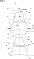
- the tire includes a tread portion 2 provided with a tread pattern having a designated rotational direction N.
- the rotational direction N may be indicated on its sidewall portions (not shown) of the tire using characters or a mark.
- the tread pattern comprises a plurality of main inclined grooves 3 spaced in a circumferential direction of the tire, and connecting grooves 4 connecting between the circumferentially adjacent main inclined grooves 4.
- Each main inclined groove 3 is configured to a V-shaped (an inverted V-shaped in FIG. 1 ) that protrude toward the rotational direction N, and extends from one tread edge Te to the other tread edge Te.
- the main inclined groove 3 may smoothly drain the water outwardly of the tread portion 2 from a tire equator C through the tread edges Te utilizing the rotation of the tire, thereby improving drainage performance.
- the tread edge Te is defined as an axially outer edge in a ground contact patch of the tread portion 2 under a standard loaded condition in which the tire is mounted on a standard wheel rim with a standard pressure and is loaded with a standard tire load at a camber angle of set to zero.
- the axial distance between the tread edges Te and Te of the tire is defined as its tread width TW.
- various dimensions, positions and the like of the tire refer to those under a standard unloaded condition of the tire unless otherwise noted.
- the standard unloaded condition is such that the tire 1 is mounted on the standard wheel rim with the standard pressure and is loaded with no tire load.
- the standard wheel rim is a wheel rim officially approved or recommended for the tire by standards organizations, i.e. JATMA, TRA, ETRTO, and the like which are effective in the area where the tire is manufactured, sold or used.
- the standard wheel rim is the "standard rim” specified in JATMA, the "Measuring Rim” in ETRTO, and the "Design Rim” in TRA or the like.
- the standard pressure and the standard tire load are the maximum air pressure and the maximum tire load for the tire specified by the same organization in the Air-pressure/Maximum-load Table or similar list.
- the standard pressure is the "maximum air pressure” in JATMA, the “Inflation Pressure” in ETRTO, and the maximum pressure given in the "Tire Load Limits at Various Cold Inflation Pressures” table in TRA or the like.
- the standard pressure is uniformly defined by 180 kPa.
- the standard pressure is uniformly defined by 100 kPa.
- the standard tire load is the "maximum load capacity" in JATMA, the “Load Capacity” in ETRTO, and the maximum value given in the above-mentioned table in TRA or the like.
- the standard tire load is uniformly defined by 88 % of the maximum tire load.
- the standard tire load is uniformly defined by 392 N.
- the main inclined groove 3 comprises a first inclined element 3A extending from the tire equator C to one of the tread edge Te (the left side tread edge in FIG. 1 ) and a second inclined element 3B extending from the tire equator C to the other one of the tread edge Te (the right side tread edge in FIG. 1 ).
- the respective first inclined element 3A and the second inclined element 3B sequentially include a center portion 3a, middle portion 3b and the shoulder portion 3c, from the tire equator C.
- the center portion 3a extends in a short length from the tire equator C axially outwardly while inclining at angle of substantially 90 degrees with respect to the circumferential direction of the tire.
- the angle of the groove 3 is measured using its groove centerline 3G.
- the angle is measured as an angle of its tangent, shown in FIG. 1 .
- the middle portion 3b extends axially outwardly from the center portion 3a while inclining at an angle ⁇ 1 smaller than that of the center portion 3a.
- the middle portion may be subjected to a large ground contact pressure during traveling.
- the angle ⁇ 1 of the middle portion 3b is preferably set in a range of not less than 5 degrees, but preferably less than 45 degrees with respect to the circumferential direction of the tire, in order to smoothly drain the water from the tread portion 2 while using an action of the tire rotation.
- the shoulder portion 3c extends axially outwardly from the middle portion 3b while inclining at an angle ⁇ 2 greater than the angle ⁇ 1 of the middle portion 3b.
- the shoulder portion 3c may be subjected to a large ground contact pressure during cornering.
- the angle ⁇ 2 of the shoulder portion 3c is preferably set in a range of from 45 to 90 degrees with respect to the circumferential direction of the tire, in order to smoothly drain the water from the tread portion 2 while using lateral force during cornering.
- the angle ⁇ 2 of the shoulder portion 3c is gradually increasing toward the tread edge Te.
- Each portions 3a, 3b and 3c of the main inclined groove 3 in accordance with the present embodiment are smoothly connected one another so as to provide better drainage performance, thereby effectively draining the water from the tire equator C axially outwardly.
- the connecting grooves 4 include a first connecting groove 4A to couple between the circumferentially adjacent first inclined elements 3A and 3A, and a second connecting groove 4B to couple between the circumferentially adjacent second inclined elements 3B and 3B.
- the connecting grooves 4 are provided axially outside the center portion 3a of the main inclined groove 3.
- the connecting grooves 4 are inclined toward the tire equator toward the anti-rotational direction N of the tire, for example.
- the connecting grooves 4 may further improve drainage performance around the tire equator C by dispersing the water toward the main inclined grooves 3.
- the main inclined groove 3 preferably has its groove width W1 in a range of from 5 to 14 mm.
- the connecting groove 4 preferably has its groove width W2 in a range of from 2 to 10 mm.
- a groove width including above means a width measured perpendicular to a longitudinal direction of the groove.
- the main inclined groove 3 and the connecting groove 4 preferably have the respective groove depths in a range of from 3 to 7 mm.
- the tread portion between main inclined grooves 3 and 3 is separated into a center block 5 and a pair of shoulder blocks 6 disposed axially both sides of the center blocks 5.
- the tread pattern is configured to a substantially symmetrically pattern with respect to the tire equator C.
- the tread pattern may be employed a non symmetrical design.
- the center block 5 is divided among the circumferentially adjacent main inclined grooves 3, 3, and a pair of connecting grooves 4 and 4.
- the center block 5 has a trapezoidal-like shape.
- the center block 5 is surrounded by the circumferentially adjacent center portions 3a of the main inclined grooves 3, a pair of middle portions 3b of the main inclined grooves 3, and a pair of connecting grooves 4.
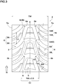
- the trapezoidal-like shape block means a block that has an axially extending leading and trailing edges 9 and 10 (shown in FIG. 2 ), and is not be required to have the trapezoidal shape according to the exact meaning.
- FIG. 2 shows an enlarged vies of center blocks 5.
- the center block 5 is provided with a center lateral groove 7 connecting between the first inclined element 3A and the second inclined element 3B.
- each center block 5 is separated into a first block element 5A between the center lateral groove 7 and the leading edge 9, and a second block element 5B between the center lateral groove 7 and the trailing edge.
- the center block 5 tends to have low rigidity around its center lateral groove 7, the center block may help to increase friction force by offering suitable contacting state against the road when braking.
- the center lateral groove 7 may effectively drain the water toward the main inclined groove 4, thereby improving wet grip.
- the center lateral groove 7 includes a pair of groove edges 7e and 7e that are configured to an arc shape protruding toward the rotational direction N of the tire, respectively. Such a center lateral groove 7 may further effectively drain the water backwardly utilizing rotational action of the tire, while improving wear resistance of the center block 5.
- the center lateral groove 7 has a groove width W3 in a range of from 1.0 to 7.0 mm.
- the first block element 5A and the second block element 5B may support each other to maintain large rigidity of the center block 5, when large circumferential shearing force is applied to the center block 5.
- the groove width W3 of the center lateral groove is less than 1.0 mm, drainage performance of the tire may be deteriorated.
- the groove width W3 of the center lateral groove is more than 7.0 mm, the first block element 5A and the second block element 5B may not support each other when large shearing force is applied, thereby deteriorating wear resistance of the center block 5.
- the center lateral groove 7 preferably has its groove depth (not shown) in a range of not less than 50%, more preferably not less than 60%, but preferably not more than 90%, more preferably not more than 80%, in relation to the groove depth of the main inclined groove 3.
- the center block 5 includes the leading edge 9, the trailing edge 10 having its axial length larger than that of the leading edge 9, and a pair of inclined side edges 11.
- the leading edge 9 includes a center part 12 having its center corresponding to the tire equator C and its width of 3% in relation to the tread width TW.
- the center part 12 of the leading edge 9 is preferably configured to an arc protruding toward the rotational direction N of the tire with a radius R1 of curvature in a range of not less than 30mm. Since such a center part 12 tends to improve rigidity of the leading edge 9, the center block 5 may offer high wear resistance. More preferably, the radius R1 of curvature of the center part 12 is preferably set in a range of not less than 45mm. Furthermore, in another aspect of the embodiment, the center part 12 may be configured to an axially extending straight line.
- the leading edge 9 of the center block 9 has its axial length L1 in a range of from 5% to 20%, more preferably in a range of from 7% to 18% in relation to the tread width TW, in order to further improve wear resistance as well as wet grip performance of the tire.
- L1 axial length
- the end of the leading edge is defined as its center point on the chamfer arc.
- the trailing edge 10 has its axial length larger than that of the leading edge 9. Furthermore, the trailing edge 10 may be configured to an arc shape that protrudes toward the rotational direction N of the tire.
- the center block 5 may have high circumferential rigidity, thereby further improving wear resistance as well as wet grip.
- the arc shape of the trailing edge 10 has its radius R2 of curvature in a range of not less than 15mm, in order to further improve the circumferential rigidity of the center block 5.
- the trailing edge 10 may be configured to an axially extending straight line.
- Each inclined side edge 11 of the center block 5 includes a first inclined side edge 14 on the first block element 5A, and a second side edge 15 on the second block element 5B.
- the first inclined side edge 14 and the second inclined side edge 15 are positioned on the same straight line or single arc.
- wet grip performance around both sides of the center block 5 may be improved due to better drainage performance of the main inclined grooves 3.
- the arc preferably has its radius in a range of not less than 20mm.
- the arc 11 may protrude either toward the tread edge or the tire equator C.
- the respective angles ⁇ 1 and ⁇ 2 of the first inclined side edge 14 and the second inclined side edge 15 are preferably set in a range of from 10 to 30 degrees with respect to the circumferential direction of the tire.
- the angles ⁇ 1 and ⁇ 2 are less than 10 degrees, wear resistance of the center block 5 may be deteriorated due to its low circumferential rigidity.
- the angles ⁇ 1 and ⁇ 2 are more than 30 degrees, wet grip of the tire may be deteriorated.
- the center blocks 5 are circumferentially arranged at pitches P in a range of from 0.5% to 2.0% in relation to a tire circumferential length on the tire equator C., for example.
- each shoulder block 6 is configured to a tapered shape toward the tire equator C so as to reduce its circumferential length L2.
- the shoulder block 6 may have large circumferential rigidity and ground contact area toward the tread edge Te, thereby further improving wear resistance of the tire.
- each shoulder block 6 is provided with a shoulder lateral groove 18.
- each shoulder block 6 is divided into a leading shoulder portion 6A and a trailing shoulder portion 6B.
- the shoulder lateral groove 18 includes a curved portion 18A extending along the main inclined groove 3, and a straight portion 18B disposed inwardly of the curved portion 18A and extending substantially along the axial direction of the tire. Such a shoulder lateral groove 18 may deliver better drainage performance as well as high pattern rigidity of the shoulder block 6, thereby further improving wear resistance.
- the straight portion 18B is preferably inclined at angle ⁇ 4 in a range of not less than 80 degrees with respect to the circumferential direction of the tire, in order to further improve pattern rigidity at its axially inner portion.
- the shoulder block 6 has its leading point 6b that is positioned forwardly with respect to the leading edge 9 of the center block 5 adjacent to the shoulder block 6 in the axial direction of the tire.
- ground contact force acting to the leading edge 9 of the center block 5 during traveling may be reduced by dispersing to both shoulder blocks 9.
- the tread pattern 2 has a central region Cr having an axial width of 50% in relation to the tread width TW.
- the central region Cr is configured to a pattern with a land ratio in a range of from 30% to 60%, in order to further improve wear resistance as well as wet grip performance of the tire. More preferably, the central region Cr has the land ratio in a range of from 40% to 50%.
- the land ratio of the central region Cr is defined as a ratio Mb/Ma of the net ground contact area Mb to the gross ground contact area Ma that is obtained by plugging all grooves up, in the central region Cr.
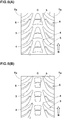
- Pneumatic tires for a four-wheel racing kart shown in FIG. 1 and Table 1 were manufactured and tested.
- Major common specifics of the tires and test methods are as follows.
- test tires were installed to a four-wheel racing kart of 100cc displacement, as its whole wheels under the following condition. Then, traction and braking performance on a dry asphalt road was evaluated by the driver's feeling. The test results were indicated using a score based on Ex.1 being 5.0 in Table 1. The larger the score, the better the performance is.
- test driver drove the racing kart above on a wet asphalt road with a puddle 5mm deep, and evaluated its wet grip performance by the driver's feeling.
- the test results were evaluated using a score based on Ex.1 being 5.0 in Table 1. The larger the score, the better the performance is.
- test driver did a time trial of 7 laps using the racing kart above on a test course of 734m long under wet condition with a puddle 5mm deep and dry condition, respectively.
- the test results were evaluated using the total lap time of wet and dry conditions, and were indicated as a score under the following conditions:
- Table 1 Test results are shown in Table 1 using an average score of the traction performance, braking performance, wet grip, and time trial, and wear resistance tests.
- Table 1-1 Ref. 1 Ref. 2 Ex. 1 Ex. 2 Ex. 3 Ex. 4 Ex. 5 Ex. 6 Ex. 7 Ex. 8 Tread pattern
- FIG. 6A FIG. 6B FIG. 1 FIG. 1 FIG. 1 FIG. 1 FIG. 1 FIG. 1 FIG. 1 FIG. 1 FIG. 1 FIG. 1 FIG. 1 FIG.
- test results show that the example tires in accordance with the present invention have excellent performance in well balance as compared to the reference tires. Although the same tests were done using different tires in size, the same results above were confirmed.
Landscapes
- Engineering & Computer Science (AREA)
- Mechanical Engineering (AREA)
- Tires In General (AREA)
Claims (9)
- Luftreifen, dereinen Laufflächenabschnitt (2) umfasst, der mit einem Laufflächenprofil mit einer vorgegebenen Drehrichtung (N) versehen ist,wobei das Laufflächenprofil (2)eine Mehrzahl von V-förmigen geneigten Hauptrillen (3), die zur Drehrichtung (N) hin vorstehen und sich von einer Laufflächenkante (Te) zu der anderen Laufflächenkante (Te) erstrecken,ein Paar Verbindungsrillen (4), die auf beiden Seiten eines Reifenäquators (C) zwischen den in Umfangsrichtung benachbarten schrägen Hauptrillen (3) angeordnet sind, undeinen Mittelblock (5) umfasst, der zwischen den in Umfangsrichtung benachbarten schrägen Hauptrillen (3, 3) und dem einen Paar Verbindungsrillen (4, 4) abgeteilt ist,dadurch gekennzeichnet, dassder Mittelblock (5) eine trapezartige Form aufweist, die eine sich quer erstreckende Vorderkante (9) und eine sich quer erstreckende Hinterkante (10) umfasst, die eine axiale Länge aufweist, die größer ist als die der Vorderkante (9),wobei die Vorderkante (9) des Mittelblocks (5) einen Mittelteil (12) mit einer axialen Länge in einem Bereich von 3 % in Relation zu einer Laufflächenbreite (TW) umfasst und der Mittelteil (12) auf eine gerade Weise ausgestaltet ist, oderwobei die Vorderkante (9) des Mittelblocks (5) einen zentralen Bereich mit einer axialen Länge in einem Bereich von 3 % Relation zu einer Laufflächenbreite (TW) umfasst und der Mittelbereich derart ausgestaltet ist, dass er einen Bogen mit einem Krümmungsradius (R1) in einem Bereich von nicht weniger als 30 mm aufweist.
- Reifen nach einem der Ansprüche 1, wobei die Vorderkante (9) eine axiale Länge in einem Bereich von 5 % bis 20 % in Relation zu einer Laufflächenbreite (TW) aufweist.
- Reifen nach Anspruch 1 oder 2,wobei jede geneigte Hauptrille (3) ein erstes geneigtes Element (3A) umfasst, das sich von dem Reifenäquator (C) zu einer der Laufflächenkante (Te) erstreckt, und ein zweites geneigtes Element (3B), das sich von dem Reifenäquator (C) zu der anderen der Laufflächenkante (Te) erstreckt, unddas Laufflächenprofil (2) ferner eine mittlere Querrille (7) umfasst, die eine Verbindung zwischen dem ersten geneigten Element (3A) und dem zweiten geneigten Element (3B) herstellt, sodass sie den Mittelblock (5) quert.
- Reifen nach Anspruch 3, wobei die mittlere Querrille (7) eine Rillenbreite (W3) in einem Bereich von 1,0 bis 7,0 mm aufweist.
- Reifen nach Anspruch 3 oder 4, wobei die mittlere Querrille (7) eine Rillentiefe in einem Bereich von 50 % bis 90 % in Relation zu einer Rillentiefe der schrägen Hauptrille aufweist.
- Reifen nach einem der Ansprüche 3, 4 oder 5,wobei der Mittelblock (5) ein erstes Blockelement (5A) zwischen der mittlere Querrille (7) und der Vorderkante (9) und ein zweites Blockelement (5B) zwischen der mittlere Querrille (7) und der Hinterkante (10) umfasst,das erste Blockelement (5A) ein Paar erste geneigte Seitenkanten (14) umfasst,das zweite Blockelement (5B) ein Paar zweite geneigte Seitenkanten (15) umfasst, unddie erste geneigte Seitenkante (14) und die zweite geneigte Seitenkante (15) auf der gleichen geraden Linie auf jeder Seite des Reifenäquator (C) angeordnet sind.
- Reifen nach Anspruch 6, wobei die ersten geneigten Seitenkanten (5A) und die zweiten geneigten Seitenkanten (5B) unter einem Winkel in einem Bereich von 10 bis 30 Grad mit Bezug auf eine Umfangsrichtung des Reifens geneigt sind.
- Reifen nach einem der Ansprüche 1 bis 7, wobei die Mittelblöcke (5) in Umfangsrichtung in Teilungsabständen (P) in einem Bereich von 0,5 % bis 2,0 % in Relation zu einer Reifenumfangslänge auf dem Reifenäquator (C) angeordnet sind.
- Reifen nach einem der Ansprüche 1 bis 8,wobei das Laufflächenprofil (2) einen zentralen Bereich (Cr) mit einer axialen Breite von 50 % in Relation zu einer Laufflächenbreite (TW) aufweist, undder zentrale Bereich (Cr) ein Landverhältnis in einem Bereich von 30 % bis 60 % aufweist.
Applications Claiming Priority (1)
| Application Number | Priority Date | Filing Date | Title |
|---|---|---|---|
| JP2013053724A JP5973942B2 (ja) | 2013-03-15 | 2013-03-15 | 空気入りタイヤ |
Publications (3)
| Publication Number | Publication Date |
|---|---|
| EP2777950A2 EP2777950A2 (de) | 2014-09-17 |
| EP2777950A3 EP2777950A3 (de) | 2017-04-12 |
| EP2777950B1 true EP2777950B1 (de) | 2019-03-13 |
Family
ID=49949564
Family Applications (1)
| Application Number | Title | Priority Date | Filing Date |
|---|---|---|---|
| EP14151542.9A Active EP2777950B1 (de) | 2013-03-15 | 2014-01-17 | Luftreifen |
Country Status (5)
| Country | Link |
|---|---|
| US (1) | US9096099B2 (de) |
| EP (1) | EP2777950B1 (de) |
| JP (1) | JP5973942B2 (de) |
| CN (1) | CN104044409B (de) |
| AU (1) | AU2014200327B2 (de) |
Families Citing this family (11)
| Publication number | Priority date | Publication date | Assignee | Title |
|---|---|---|---|---|
| JP5782480B2 (ja) * | 2013-07-05 | 2015-09-24 | 住友ゴム工業株式会社 | 空気入りタイヤ |
| JP6336409B2 (ja) * | 2015-05-26 | 2018-06-06 | 住友ゴム工業株式会社 | 冬用タイヤ |
| JP6360459B2 (ja) * | 2015-05-26 | 2018-07-18 | 住友ゴム工業株式会社 | 冬用タイヤ |
| JP2017065605A (ja) | 2015-10-01 | 2017-04-06 | 住友ゴム工業株式会社 | 自動車用タイヤ |
| JP6623764B2 (ja) * | 2016-01-06 | 2019-12-25 | 住友ゴム工業株式会社 | 空気入りタイヤ |
| KR101859839B1 (ko) * | 2016-10-17 | 2018-05-18 | 한국타이어 주식회사 | 공기입 타이어 |
| JP7293840B2 (ja) * | 2019-04-23 | 2023-06-20 | 横浜ゴム株式会社 | 空気入りタイヤ |
| JP6699079B1 (ja) | 2019-09-27 | 2020-05-27 | 住友ゴム工業株式会社 | 空気入りタイヤ |
| JP7497607B2 (ja) * | 2020-04-30 | 2024-06-11 | 住友ゴム工業株式会社 | タイヤ |
| JP6804054B1 (ja) | 2020-05-07 | 2020-12-23 | 住友ゴム工業株式会社 | 乗用車用空気入りラジアルタイヤ |
| JP1697146S (de) * | 2021-02-10 | 2021-10-18 |
Citations (2)
| Publication number | Priority date | Publication date | Assignee | Title |
|---|---|---|---|---|
| JPS61108005A (ja) * | 1984-10-31 | 1986-05-26 | Bridgestone Corp | 空気入りタイヤ |
| JPH09300917A (ja) * | 1996-05-10 | 1997-11-25 | Toyo Tire & Rubber Co Ltd | 空気入りタイヤ |
Family Cites Families (13)
| Publication number | Priority date | Publication date | Assignee | Title |
|---|---|---|---|---|
| USD265187S (en) * | 1980-06-12 | 1982-06-29 | Compagnie Generale Des Etablissements Michelin | Tire |
| JPH04126612A (ja) * | 1990-09-19 | 1992-04-27 | Bridgestone Corp | 空気入りタイヤ |
| JPH07132710A (ja) * | 1993-11-12 | 1995-05-23 | Bridgestone Corp | 冬用空気入タイヤ |
| JP2698556B2 (ja) * | 1995-07-06 | 1998-01-19 | 株式会社ブリヂストン | 空気入りラジアルタイヤ |
| JP4570262B2 (ja) * | 2001-02-26 | 2010-10-27 | 株式会社ブリヂストン | 空気入りタイヤ |
| JP4421432B2 (ja) * | 2004-09-17 | 2010-02-24 | 株式会社ブリヂストン | 空気入りタイヤ |
| USD549157S1 (en) * | 2006-05-02 | 2007-08-21 | The Goodyear Tire & Rubber Company | Tire tread |
| JP4299870B2 (ja) | 2007-11-29 | 2009-07-22 | 住友ゴム工業株式会社 | 空気入りタイヤ |
| WO2009069585A1 (ja) * | 2007-11-28 | 2009-06-04 | Sumitomo Rubber Industries, Ltd. | 空気入りタイヤ |
| USD626499S1 (en) * | 2009-12-28 | 2010-11-02 | The Goodyear Tire & Rubber Company | Tire for automobile |
| JP5222334B2 (ja) * | 2010-09-09 | 2013-06-26 | 住友ゴム工業株式会社 | 空気入りタイヤ |
| JP5727502B2 (ja) * | 2010-10-22 | 2015-06-03 | 株式会社ブリヂストン | 建設車両用重荷重空気入りタイヤ |
| JP5261465B2 (ja) * | 2010-11-29 | 2013-08-14 | 住友ゴム工業株式会社 | レーシングカート用タイヤ |
-
2013
- 2013-03-15 JP JP2013053724A patent/JP5973942B2/ja not_active Expired - Fee Related
- 2013-09-05 CN CN201310400580.9A patent/CN104044409B/zh not_active Expired - Fee Related
-
2014
- 2014-01-17 EP EP14151542.9A patent/EP2777950B1/de active Active
- 2014-01-20 AU AU2014200327A patent/AU2014200327B2/en not_active Ceased
- 2014-01-23 US US14/161,922 patent/US9096099B2/en not_active Expired - Fee Related
Patent Citations (2)
| Publication number | Priority date | Publication date | Assignee | Title |
|---|---|---|---|---|
| JPS61108005A (ja) * | 1984-10-31 | 1986-05-26 | Bridgestone Corp | 空気入りタイヤ |
| JPH09300917A (ja) * | 1996-05-10 | 1997-11-25 | Toyo Tire & Rubber Co Ltd | 空気入りタイヤ |
Also Published As
| Publication number | Publication date |
|---|---|
| CN104044409A (zh) | 2014-09-17 |
| AU2014200327B2 (en) | 2017-04-20 |
| AU2014200327A1 (en) | 2014-10-02 |
| JP5973942B2 (ja) | 2016-08-23 |
| EP2777950A3 (de) | 2017-04-12 |
| JP2014177238A (ja) | 2014-09-25 |
| EP2777950A2 (de) | 2014-09-17 |
| US9096099B2 (en) | 2015-08-04 |
| US20140261937A1 (en) | 2014-09-18 |
| CN104044409B (zh) | 2017-10-03 |
Similar Documents
| Publication | Publication Date | Title |
|---|---|---|
| EP2777950B1 (de) | Luftreifen | |
| EP3153334B1 (de) | Reifen | |
| EP3189983B1 (de) | Luftreifen | |
| EP3000621B1 (de) | Luftreifen | |
| EP3000622B1 (de) | Luftreifen | |
| EP3015288B1 (de) | Luftreifen | |
| EP2614966B1 (de) | LKW-Luftreifen | |
| EP2982520B1 (de) | Luftreifen | |
| US9150056B2 (en) | Pneumatic tire | |
| EP3012119B1 (de) | Luftreifen | |
| EP2772370B1 (de) | Luftreifen | |
| EP3269564A1 (de) | Luftreifen | |
| EP3078506B1 (de) | Luftreifen | |
| US10272725B2 (en) | Pneumatic tire | |
| EP3127715B1 (de) | Fahrzeugluftreifen | |
| US20160257172A1 (en) | Pneumatic tire | |
| EP3335910B1 (de) | Reifen | |
| US20180111421A1 (en) | Tire | |
| EP3403852B1 (de) | Reifen | |
| EP3318421B1 (de) | Reifen | |
| EP3456551B1 (de) | Reifen | |
| EP3421265B1 (de) | Reifen | |
| EP3275699B1 (de) | Reifen | |
| EP3075571A2 (de) | Reifen | |
| EP2821257B1 (de) | Luftreifen |
Legal Events
| Date | Code | Title | Description |
|---|---|---|---|
| PUAI | Public reference made under article 153(3) epc to a published international application that has entered the european phase |
Free format text: ORIGINAL CODE: 0009012 |
|
| 17P | Request for examination filed |
Effective date: 20140117 |
|
| AK | Designated contracting states |
Kind code of ref document: A2 Designated state(s): AL AT BE BG CH CY CZ DE DK EE ES FI FR GB GR HR HU IE IS IT LI LT LU LV MC MK MT NL NO PL PT RO RS SE SI SK SM TR |
|
| AX | Request for extension of the european patent |
Extension state: BA ME |
|
| PUAL | Search report despatched |
Free format text: ORIGINAL CODE: 0009013 |
|
| AK | Designated contracting states |
Kind code of ref document: A3 Designated state(s): AL AT BE BG CH CY CZ DE DK EE ES FI FR GB GR HR HU IE IS IT LI LT LU LV MC MK MT NL NO PL PT RO RS SE SI SK SM TR |
|
| AX | Request for extension of the european patent |
Extension state: BA ME |
|
| RIC1 | Information provided on ipc code assigned before grant |
Ipc: B60C 11/03 20060101AFI20170308BHEP Ipc: B60C 11/11 20060101ALI20170308BHEP |
|
| STAA | Information on the status of an ep patent application or granted ep patent |
Free format text: STATUS: REQUEST FOR EXAMINATION WAS MADE |
|
| R17P | Request for examination filed (corrected) |
Effective date: 20170621 |
|
| RBV | Designated contracting states (corrected) |
Designated state(s): AL AT BE BG CH CY CZ DE DK EE ES FI FR GB GR HR HU IE IS IT LI LT LU LV MC MK MT NL NO PL PT RO RS SE SI SK SM TR |
|
| STAA | Information on the status of an ep patent application or granted ep patent |
Free format text: STATUS: EXAMINATION IS IN PROGRESS |
|
| 17Q | First examination report despatched |
Effective date: 20180208 |
|
| GRAP | Despatch of communication of intention to grant a patent |
Free format text: ORIGINAL CODE: EPIDOSNIGR1 |
|
| STAA | Information on the status of an ep patent application or granted ep patent |
Free format text: STATUS: GRANT OF PATENT IS INTENDED |
|
| INTG | Intention to grant announced |
Effective date: 20181015 |
|
| GRAS | Grant fee paid |
Free format text: ORIGINAL CODE: EPIDOSNIGR3 |
|
| GRAA | (expected) grant |
Free format text: ORIGINAL CODE: 0009210 |
|
| STAA | Information on the status of an ep patent application or granted ep patent |
Free format text: STATUS: THE PATENT HAS BEEN GRANTED |
|
| AK | Designated contracting states |
Kind code of ref document: B1 Designated state(s): AL AT BE BG CH CY CZ DE DK EE ES FI FR GB GR HR HU IE IS IT LI LT LU LV MC MK MT NL NO PL PT RO RS SE SI SK SM TR |
|
| REG | Reference to a national code |
Ref country code: GB Ref legal event code: FG4D |
|
| REG | Reference to a national code |
Ref country code: CH Ref legal event code: EP Ref country code: AT Ref legal event code: REF Ref document number: 1107181 Country of ref document: AT Kind code of ref document: T Effective date: 20190315 |
|
| REG | Reference to a national code |
Ref country code: IE Ref legal event code: FG4D |
|
| REG | Reference to a national code |
Ref country code: DE Ref legal event code: R096 Ref document number: 602014042658 Country of ref document: DE |
|
| REG | Reference to a national code |
Ref country code: NL Ref legal event code: MP Effective date: 20190313 |
|
| REG | Reference to a national code |
Ref country code: LT Ref legal event code: MG4D |
|
| PG25 | Lapsed in a contracting state [announced via postgrant information from national office to epo] |
Ref country code: SE Free format text: LAPSE BECAUSE OF FAILURE TO SUBMIT A TRANSLATION OF THE DESCRIPTION OR TO PAY THE FEE WITHIN THE PRESCRIBED TIME-LIMIT Effective date: 20190313 Ref country code: FI Free format text: LAPSE BECAUSE OF FAILURE TO SUBMIT A TRANSLATION OF THE DESCRIPTION OR TO PAY THE FEE WITHIN THE PRESCRIBED TIME-LIMIT Effective date: 20190313 Ref country code: NO Free format text: LAPSE BECAUSE OF FAILURE TO SUBMIT A TRANSLATION OF THE DESCRIPTION OR TO PAY THE FEE WITHIN THE PRESCRIBED TIME-LIMIT Effective date: 20190613 Ref country code: LT Free format text: LAPSE BECAUSE OF FAILURE TO SUBMIT A TRANSLATION OF THE DESCRIPTION OR TO PAY THE FEE WITHIN THE PRESCRIBED TIME-LIMIT Effective date: 20190313 |
|
| PG25 | Lapsed in a contracting state [announced via postgrant information from national office to epo] |
Ref country code: GR Free format text: LAPSE BECAUSE OF FAILURE TO SUBMIT A TRANSLATION OF THE DESCRIPTION OR TO PAY THE FEE WITHIN THE PRESCRIBED TIME-LIMIT Effective date: 20190614 Ref country code: NL Free format text: LAPSE BECAUSE OF FAILURE TO SUBMIT A TRANSLATION OF THE DESCRIPTION OR TO PAY THE FEE WITHIN THE PRESCRIBED TIME-LIMIT Effective date: 20190313 Ref country code: HR Free format text: LAPSE BECAUSE OF FAILURE TO SUBMIT A TRANSLATION OF THE DESCRIPTION OR TO PAY THE FEE WITHIN THE PRESCRIBED TIME-LIMIT Effective date: 20190313 Ref country code: LV Free format text: LAPSE BECAUSE OF FAILURE TO SUBMIT A TRANSLATION OF THE DESCRIPTION OR TO PAY THE FEE WITHIN THE PRESCRIBED TIME-LIMIT Effective date: 20190313 Ref country code: BG Free format text: LAPSE BECAUSE OF FAILURE TO SUBMIT A TRANSLATION OF THE DESCRIPTION OR TO PAY THE FEE WITHIN THE PRESCRIBED TIME-LIMIT Effective date: 20190613 Ref country code: RS Free format text: LAPSE BECAUSE OF FAILURE TO SUBMIT A TRANSLATION OF THE DESCRIPTION OR TO PAY THE FEE WITHIN THE PRESCRIBED TIME-LIMIT Effective date: 20190313 |
|
| REG | Reference to a national code |
Ref country code: AT Ref legal event code: MK05 Ref document number: 1107181 Country of ref document: AT Kind code of ref document: T Effective date: 20190313 |
|
| PG25 | Lapsed in a contracting state [announced via postgrant information from national office to epo] |
Ref country code: SK Free format text: LAPSE BECAUSE OF FAILURE TO SUBMIT A TRANSLATION OF THE DESCRIPTION OR TO PAY THE FEE WITHIN THE PRESCRIBED TIME-LIMIT Effective date: 20190313 Ref country code: RO Free format text: LAPSE BECAUSE OF FAILURE TO SUBMIT A TRANSLATION OF THE DESCRIPTION OR TO PAY THE FEE WITHIN THE PRESCRIBED TIME-LIMIT Effective date: 20190313 Ref country code: CZ Free format text: LAPSE BECAUSE OF FAILURE TO SUBMIT A TRANSLATION OF THE DESCRIPTION OR TO PAY THE FEE WITHIN THE PRESCRIBED TIME-LIMIT Effective date: 20190313 Ref country code: EE Free format text: LAPSE BECAUSE OF FAILURE TO SUBMIT A TRANSLATION OF THE DESCRIPTION OR TO PAY THE FEE WITHIN THE PRESCRIBED TIME-LIMIT Effective date: 20190313 Ref country code: PT Free format text: LAPSE BECAUSE OF FAILURE TO SUBMIT A TRANSLATION OF THE DESCRIPTION OR TO PAY THE FEE WITHIN THE PRESCRIBED TIME-LIMIT Effective date: 20190713 Ref country code: AL Free format text: LAPSE BECAUSE OF FAILURE TO SUBMIT A TRANSLATION OF THE DESCRIPTION OR TO PAY THE FEE WITHIN THE PRESCRIBED TIME-LIMIT Effective date: 20190313 Ref country code: ES Free format text: LAPSE BECAUSE OF FAILURE TO SUBMIT A TRANSLATION OF THE DESCRIPTION OR TO PAY THE FEE WITHIN THE PRESCRIBED TIME-LIMIT Effective date: 20190313 |
|
| PG25 | Lapsed in a contracting state [announced via postgrant information from national office to epo] |
Ref country code: SM Free format text: LAPSE BECAUSE OF FAILURE TO SUBMIT A TRANSLATION OF THE DESCRIPTION OR TO PAY THE FEE WITHIN THE PRESCRIBED TIME-LIMIT Effective date: 20190313 Ref country code: PL Free format text: LAPSE BECAUSE OF FAILURE TO SUBMIT A TRANSLATION OF THE DESCRIPTION OR TO PAY THE FEE WITHIN THE PRESCRIBED TIME-LIMIT Effective date: 20190313 |
|
| REG | Reference to a national code |
Ref country code: DE Ref legal event code: R097 Ref document number: 602014042658 Country of ref document: DE |
|
| PG25 | Lapsed in a contracting state [announced via postgrant information from national office to epo] |
Ref country code: AT Free format text: LAPSE BECAUSE OF FAILURE TO SUBMIT A TRANSLATION OF THE DESCRIPTION OR TO PAY THE FEE WITHIN THE PRESCRIBED TIME-LIMIT Effective date: 20190313 Ref country code: IS Free format text: LAPSE BECAUSE OF FAILURE TO SUBMIT A TRANSLATION OF THE DESCRIPTION OR TO PAY THE FEE WITHIN THE PRESCRIBED TIME-LIMIT Effective date: 20190713 |
|
| PLBE | No opposition filed within time limit |
Free format text: ORIGINAL CODE: 0009261 |
|
| STAA | Information on the status of an ep patent application or granted ep patent |
Free format text: STATUS: NO OPPOSITION FILED WITHIN TIME LIMIT |
|
| PG25 | Lapsed in a contracting state [announced via postgrant information from national office to epo] |
Ref country code: DK Free format text: LAPSE BECAUSE OF FAILURE TO SUBMIT A TRANSLATION OF THE DESCRIPTION OR TO PAY THE FEE WITHIN THE PRESCRIBED TIME-LIMIT Effective date: 20190313 |
|
| 26N | No opposition filed |
Effective date: 20191216 |
|
| PG25 | Lapsed in a contracting state [announced via postgrant information from national office to epo] |
Ref country code: SI Free format text: LAPSE BECAUSE OF FAILURE TO SUBMIT A TRANSLATION OF THE DESCRIPTION OR TO PAY THE FEE WITHIN THE PRESCRIBED TIME-LIMIT Effective date: 20190313 |
|
| PG25 | Lapsed in a contracting state [announced via postgrant information from national office to epo] |
Ref country code: TR Free format text: LAPSE BECAUSE OF FAILURE TO SUBMIT A TRANSLATION OF THE DESCRIPTION OR TO PAY THE FEE WITHIN THE PRESCRIBED TIME-LIMIT Effective date: 20190313 |
|
| PG25 | Lapsed in a contracting state [announced via postgrant information from national office to epo] |
Ref country code: MC Free format text: LAPSE BECAUSE OF FAILURE TO SUBMIT A TRANSLATION OF THE DESCRIPTION OR TO PAY THE FEE WITHIN THE PRESCRIBED TIME-LIMIT Effective date: 20190313 |
|
| REG | Reference to a national code |
Ref country code: CH Ref legal event code: PL |
|
| GBPC | Gb: european patent ceased through non-payment of renewal fee |
Effective date: 20200117 |
|
| REG | Reference to a national code |
Ref country code: BE Ref legal event code: MM Effective date: 20200131 |
|
| PG25 | Lapsed in a contracting state [announced via postgrant information from national office to epo] |
Ref country code: LU Free format text: LAPSE BECAUSE OF NON-PAYMENT OF DUE FEES Effective date: 20200117 Ref country code: GB Free format text: LAPSE BECAUSE OF NON-PAYMENT OF DUE FEES Effective date: 20200117 Ref country code: FR Free format text: LAPSE BECAUSE OF NON-PAYMENT OF DUE FEES Effective date: 20200131 |
|
| PG25 | Lapsed in a contracting state [announced via postgrant information from national office to epo] |
Ref country code: CH Free format text: LAPSE BECAUSE OF NON-PAYMENT OF DUE FEES Effective date: 20200131 Ref country code: LI Free format text: LAPSE BECAUSE OF NON-PAYMENT OF DUE FEES Effective date: 20200131 Ref country code: BE Free format text: LAPSE BECAUSE OF NON-PAYMENT OF DUE FEES Effective date: 20200131 |
|
| PG25 | Lapsed in a contracting state [announced via postgrant information from national office to epo] |
Ref country code: IE Free format text: LAPSE BECAUSE OF NON-PAYMENT OF DUE FEES Effective date: 20200117 |
|
| PG25 | Lapsed in a contracting state [announced via postgrant information from national office to epo] |
Ref country code: MT Free format text: LAPSE BECAUSE OF FAILURE TO SUBMIT A TRANSLATION OF THE DESCRIPTION OR TO PAY THE FEE WITHIN THE PRESCRIBED TIME-LIMIT Effective date: 20190313 Ref country code: CY Free format text: LAPSE BECAUSE OF FAILURE TO SUBMIT A TRANSLATION OF THE DESCRIPTION OR TO PAY THE FEE WITHIN THE PRESCRIBED TIME-LIMIT Effective date: 20190313 |
|
| PG25 | Lapsed in a contracting state [announced via postgrant information from national office to epo] |
Ref country code: MK Free format text: LAPSE BECAUSE OF FAILURE TO SUBMIT A TRANSLATION OF THE DESCRIPTION OR TO PAY THE FEE WITHIN THE PRESCRIBED TIME-LIMIT Effective date: 20190313 |
|
| PGFP | Annual fee paid to national office [announced via postgrant information from national office to epo] |
Ref country code: IT Payment date: 20221213 Year of fee payment: 10 Ref country code: DE Payment date: 20221130 Year of fee payment: 10 |
|
| P01 | Opt-out of the competence of the unified patent court (upc) registered |
Effective date: 20230510 |
|
| REG | Reference to a national code |
Ref country code: DE Ref legal event code: R119 Ref document number: 602014042658 Country of ref document: DE |