EP2129986B1 - Dosierung und/oder förderung von pulvrigen und/oder rieselfähigen feststoffen - Google Patents
Dosierung und/oder förderung von pulvrigen und/oder rieselfähigen feststoffen Download PDFInfo
- Publication number
- EP2129986B1 EP2129986B1 EP08707613.9A EP08707613A EP2129986B1 EP 2129986 B1 EP2129986 B1 EP 2129986B1 EP 08707613 A EP08707613 A EP 08707613A EP 2129986 B1 EP2129986 B1 EP 2129986B1
- Authority
- EP
- European Patent Office
- Prior art keywords
- piston
- inflow
- slotted
- interior
- outflow
- Prior art date
- Legal status (The legal status is an assumption and is not a legal conclusion. Google has not performed a legal analysis and makes no representation as to the accuracy of the status listed.)
- Active
Links
Images


Classifications
-
- F—MECHANICAL ENGINEERING; LIGHTING; HEATING; WEAPONS; BLASTING
- F27—FURNACES; KILNS; OVENS; RETORTS
- F27D—DETAILS OR ACCESSORIES OF FURNACES, KILNS, OVENS OR RETORTS, IN SO FAR AS THEY ARE OF KINDS OCCURRING IN MORE THAN ONE KIND OF FURNACE
- F27D3/00—Charging; Discharging; Manipulation of charge
- F27D3/16—Introducing a fluid jet or current into the charge
-
- B—PERFORMING OPERATIONS; TRANSPORTING
- B22—CASTING; POWDER METALLURGY
- B22F—WORKING METALLIC POWDER; MANUFACTURE OF ARTICLES FROM METALLIC POWDER; MAKING METALLIC POWDER; APPARATUS OR DEVICES SPECIALLY ADAPTED FOR METALLIC POWDER
- B22F3/00—Manufacture of workpieces or articles from metallic powder characterised by the manner of compacting or sintering; Apparatus specially adapted therefor ; Presses and furnaces
- B22F3/004—Filling molds with powder
-
- B—PERFORMING OPERATIONS; TRANSPORTING
- B65—CONVEYING; PACKING; STORING; HANDLING THIN OR FILAMENTARY MATERIAL
- B65G—TRANSPORT OR STORAGE DEVICES, e.g. CONVEYORS FOR LOADING OR TIPPING, SHOP CONVEYOR SYSTEMS OR PNEUMATIC TUBE CONVEYORS
- B65G53/00—Conveying materials in bulk through troughs, pipes or tubes by floating the materials or by flow of gas, liquid or foam
- B65G53/34—Details
- B65G53/40—Feeding or discharging devices
- B65G53/46—Gates or sluices, e.g. rotary wheels
- B65G53/4683—Gates or sluices, e.g. rotary wheels with a reciprocating mover acting directly on material
-
- C—CHEMISTRY; METALLURGY
- C21—METALLURGY OF IRON
- C21C—PROCESSING OF PIG-IRON, e.g. REFINING, MANUFACTURE OF WROUGHT-IRON OR STEEL; TREATMENT IN MOLTEN STATE OF FERROUS ALLOYS
- C21C7/00—Treating molten ferrous alloys, e.g. steel, not covered by groups C21C1/00 - C21C5/00
- C21C7/0037—Treating molten ferrous alloys, e.g. steel, not covered by groups C21C1/00 - C21C5/00 by injecting powdered material
-
- F—MECHANICAL ENGINEERING; LIGHTING; HEATING; WEAPONS; BLASTING
- F27—FURNACES; KILNS; OVENS; RETORTS
- F27D—DETAILS OR ACCESSORIES OF FURNACES, KILNS, OVENS OR RETORTS, IN SO FAR AS THEY ARE OF KINDS OCCURRING IN MORE THAN ONE KIND OF FURNACE
- F27D3/00—Charging; Discharging; Manipulation of charge
- F27D3/0033—Charging; Discharging; Manipulation of charge charging of particulate material
-
- F—MECHANICAL ENGINEERING; LIGHTING; HEATING; WEAPONS; BLASTING
- F27—FURNACES; KILNS; OVENS; RETORTS
- F27D—DETAILS OR ACCESSORIES OF FURNACES, KILNS, OVENS OR RETORTS, IN SO FAR AS THEY ARE OF KINDS OCCURRING IN MORE THAN ONE KIND OF FURNACE
- F27D3/00—Charging; Discharging; Manipulation of charge
- F27D3/18—Charging particulate material using a fluid carrier
-
- G—PHYSICS
- G01—MEASURING; TESTING
- G01F—MEASURING VOLUME, VOLUME FLOW, MASS FLOW OR LIQUID LEVEL; METERING BY VOLUME
- G01F11/00—Apparatus requiring external operation adapted at each repeated and identical operation to measure and separate a predetermined volume of fluid or fluent solid material from a supply or container, without regard to weight, and to deliver it
- G01F11/10—Apparatus requiring external operation adapted at each repeated and identical operation to measure and separate a predetermined volume of fluid or fluent solid material from a supply or container, without regard to weight, and to deliver it with measuring chambers moved during operation
- G01F11/12—Apparatus requiring external operation adapted at each repeated and identical operation to measure and separate a predetermined volume of fluid or fluent solid material from a supply or container, without regard to weight, and to deliver it with measuring chambers moved during operation of the valve type, i.e. the separating being effected by fluid-tight or powder-tight movements
- G01F11/14—Apparatus requiring external operation adapted at each repeated and identical operation to measure and separate a predetermined volume of fluid or fluent solid material from a supply or container, without regard to weight, and to deliver it with measuring chambers moved during operation of the valve type, i.e. the separating being effected by fluid-tight or powder-tight movements wherein the measuring chamber reciprocates
- G01F11/18—Apparatus requiring external operation adapted at each repeated and identical operation to measure and separate a predetermined volume of fluid or fluent solid material from a supply or container, without regard to weight, and to deliver it with measuring chambers moved during operation of the valve type, i.e. the separating being effected by fluid-tight or powder-tight movements wherein the measuring chamber reciprocates for fluent solid material
-
- C—CHEMISTRY; METALLURGY
- C21—METALLURGY OF IRON
- C21C—PROCESSING OF PIG-IRON, e.g. REFINING, MANUFACTURE OF WROUGHT-IRON OR STEEL; TREATMENT IN MOLTEN STATE OF FERROUS ALLOYS
- C21C5/00—Manufacture of carbon-steel, e.g. plain mild steel, medium carbon steel or cast steel or stainless steel
- C21C5/28—Manufacture of steel in the converter
- C21C5/42—Constructional features of converters
- C21C5/46—Details or accessories
- C21C5/466—Charging device for converters
Definitions
- the present invention relates to a device for metering and / or conveying powdery and / or free-flowing solids, in particular powder, dusts and / or granules, comprising a housing with at least one funnel-shaped inlet, at least one cone-shaped outlet and at least one, at least one piston speed-controlled moving forward or backward driving linear drive.
- a generic device is in particular from the DE 195 38 622 C1 The disclosures of which are hereby explicitly referenced.
- the DE 195 38 622 C1 known device is the entire interior of the device during the process flow under a pneumatic overpressure. Due to the gravitational pull, the quantities fed through the working piston, specifically metered for transport out of the apparatus, fall into an outlet cone and are pneumatically conveyed by gas quantities introduced into the outlet cone through the single outlet of the apparatus into a conduit leading to the target location.
- the working piston of the device pushes the solid column lying in the housing space in front of the piston horizontally forward at a programmed feed rate.
- the DE 3422486 A1 describes a dispenser for dispensing granular or powdery products. This creates a gas-permeable connection between the inlet region and outlet region during actuation of the conveyor.
- US Pat. No. 3,669,318 discloses a device for conveying material that can also be used under overpressure conditions.
- the present invention seeks to improve the generic dosage and / or promotion of powdery and / or free-flowing solids.
- a device which mechanically by the advance of a piston, which is variable in its feed speed, powder, dusts and / or granules in a preferably cone-shaped outlet (outlet cone) fall, the piston by its particular configuration to promotional material does not push in front of him but carries in itself.
- the delivery method is changed in such a way that the horizontal solid column is exposed to as little as possible or only a small internal pressure in the material structure during advancement and thus is not or only slightly compressed. Consequently, no high frictional forces on the inner wall, the total resistance during advancement remains low in the material to be conveyed no lump formation and the required drive power of the linear drive is reduced.
- a generic device for metering and / or conveying of powdery and / or free-flowing solids, in particular powder, dusts and / or granules comprising a housing with at least one funnel-shaped inlet, at least one cone-shaped outlet and at least one, at least one piston speed-controlled or moving back linear driving the piston is at least partially formed as a hollow body with an inlet facing the opening and an outlet facing the outlet.
- the piston is advantageously designed so that the extension provides a cavity; in which the material to be conveyed can flow or fall.
- the cavity is in cross section advantageously circular, partially circular and / or curved combined with straight lines and / or only consisting of straight lines in the form of polygons.
- the extended region of the piston in the length of the funnel-shaped inlet (inlet funnel) in the longitudinal direction (longitudinal direction) of the piston at the top and / or bottom at least one longitudinal slot.
- the inlet is made through longitudinal slots and / or through rows of holes.
- the material that fills the entire interior of the housing by opening the inlet or inlet valve through the funnel-shaped inlet (inlet funnel) also flows through the opening formed by the upper slot of the piston, the inlet facing the piston and fills the entire interior of the essentially formed as a hollow body piston.
- the material is not compressed during conveying with the hollow body, preferably slotted piston, since it is enclosed in the piston and is formally supported by the piston and thus pressing forces on the inner wall of the housing space do not arise.
- two devices according to the invention or a device with two pistons according to the invention are advantageously used or used.
- a single device or with a device with a piston intermittent promotion is possible.
- a particularly preferred embodiment of the invention relates to a device for metering and / or conveying powdery and / or free-flowing solids and is a further development of the device according to the DE 195 38 622 C1 ,
- the interior of the housing has an inlet funnel in the upper part, which is shaped so that when fully retracted piston and when opening the inlet valve arranged above the entire interior in the inlet region and located in this area, through slots at the top and bottom open piston entirely filled with material.
- On the non-driven side of the piston is in the working direction of the piston behind the Abstreiflager the outlet region arranged with an outlet cone that the advanced material falls into the outlet cone and is pneumatically accelerated by introduced into the outlet cone conveying gas in a line to the destination.
- the piston is not designed as a plunger, which advances the material with its piston surface, but advantageously as a vessel which receives the material to be conveyed and primarily does not push but carries in itself. Furthermore, the piston is significantly longer than the piston designed as a plunger according to the device according to the DE 195 38 622 C1 , Further, the piston is additionally supported and sealed at the free end (non-driven side) of the piston with a stripping bearing. In particular, the stripping bearing has the task of guiding the long piston and sealing off the inlet region to the outlet region in such a way that no material can pass through the bearing.
- a bypass from one to the other side of the stripper ensures absolute pressure equality in front of and behind the scraper bearing so that in particular an uncontrolled shooting through of material is excluded.
- the piston interior is prematurely sealed with partitions at an angle corresponding to the angle of repose of the material, to the outside.
- the advantage of the device according to the invention over the device according to the DE 195 38 622 C1 is in particular that the material is not pushed by the piston but is worn, no frictional resistance to the inner wall of the housing arise and consequently significantly less feed force is required. This results in no compaction of the material, so that the bulk density from the beginning to the end of a working stroke is always loose and equal.
- the material to be pumped will fall into the outlet cone according to the compression of the horizontal solids column. The exact time of the start of delivery is thus not exactly determinable and not exactly reproducible.
- Another advantage over the device according to the DE 195 38 622 C1 is that the beginning of the discharge is exactly determinable and advantageously coincides with the time at which the lower slot of the piston passes from the Abstreiflager at the outlet edge in the outlet region. Switching from one to the other piston are advantageously to ensure seamless.
- powdery and / or free-flowing solids can advantageously be supplied with variable volume control pneumatically in flight and / or dense stream through a delivery line to a destination, which is a reactor or a similar vessel and is under atmospheric pressure or under pressure.
- the invention like the device according to the DE 195 38 622 C1 - its origin and finds, there use in the desulphurisation of pig iron.
- magnesium granules with a grain size of about 0.2 mm to about 0.8 mm is constant, variably adjustable, according to a predetermined target amount, injected against fluctuating pressures between about 3.5 bar and about 5.5 bar in a molten pig iron.
- the invention thereby advantageously the extended task, other solids such as soda, calcium carbide and / or lime in dust and / or granular form volume controlled pneumatically injected into pig iron melts.
- a multi-injection desulfurization with Dosier fingervoriquesen can be operated in contrast to conventional desulfurization advantageously fully automatically without personnel monitoring.
- the uniform promotion and the disregard of required flow improvers and / or required particle sizes achieve significant improvements in efficiency compared to otherwise common today unsatisfactory and poor efficiencies of the desulfurization, especially the calcium carbide of 0.3.
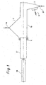
- a device is shown, as known from the prior art according to the DE 195 38 622 C1 is known.
- the device consists essentially of a housing 15 with inlet funnel 2 and outlet cone 3, a piston 19 with sealing bearing 5.
- the open inlet valve 16 material flows into the housing 15 and fills it completely.
- the outlet valve 17 and the delivery gas valve 9 are opened and the linear actuator 18 pushes the plunger 37 into the housing 15.
- the material in the housing located in front of the plunger 37 is compressed and commences according to the compressibility of the horizontal column of material and the frictional forces of the material on the inner wall of the housing to fall after a corresponding feed distance in the outlet cone.
- the plunger 37 has a bearing, the so-called sealing bearing 5, and works with its piston surface on the principle of a plunger.
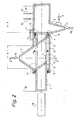
- Fig. 2 is a preferred embodiment of a device with slotted piston according to the invention 1.
- the device consists essentially of the housing 15 with inlet funnel 2 and outlet cone 3, the slotted piston 1 with sealing bearing 5 and stripping 4.
- the difference Fig. 1 or for DE 195 38 62 is in particular that the slotted piston 1 is significantly longer than the plunger 37, not pushes the material in front of him after the plunger principle and opens his piston in the inlet region 6 through a slot-like opening with fully retracted linear drive 18, the slot area through the partitions 12 and 13 is closed to the ends of the slotted piston 1 and an additional stripping bearing 4 has.
- the stripping bearing 4 has the task to store the slotted piston and to guide and prevent material passes the slotted piston 1 over in the outlet region 7.
- the stripping 4 is not gas pressure tight.
- the bypass 8 ensures equal pressure in front of and behind the stripping 4.
- Fig. 3 shows Fig. 2 in section A - A and additionally a reservoir 29, which is weighed by the balance 30 and by the compensator 31 is free of force shunts.
- the material which flows in a reverse movement of the piston 1 from the supply vessel 29 through the inlet valve 16 into the device and thus fills the empty, slotted piston 1, is weighed by the balance 30. With this weighing value, the amount of material in the slotted piston can be determined and thus also exactly the discharge quantity per feed distance can be determined.
- the determination of the filling quantity is determined or determined empirically by calculating the volume multiplied by the bulk density of the material to be conveyed.
- the upper slot 10 in the slotted piston 1 is the slot through which the material flows into the slotted piston 1.
- the lower slot 11 is the slot through which the material falls out of the slotted piston 1 at the outlet edge 19 and falls into the outlet cone 3.
- the slots 10 and 11 can also be designed as a row of holes. Also, the slotted piston 1 in the region of the two slots 10 and 11 around with holes, similar to a sieve, be performed.
- Fig. 4 shows a preferred embodiment of the interior of the slotted piston 1.
- the strong inclination of the outlet edges ensures that the material flows out of the slotted piston 1 entirely.
- Fig. 5 shows another embodiment of the interior of the slotted piston 1. Again, by the contrary to the in Fig. 3 shown slotted piston 1 ensures that the material flows out of the slotted piston 1 entirely.
- the fluidizing dividing wall 34 When filling, the fluidizing dividing wall 34 is in the inlet position 36 and prevents uncontrolled flow of the pouring column of the material in the direction of the outlet edge 19 and ensures a defined position of the pouring column.
- the adjustment cylinder 35 pulls the fluidization partition in the position shown and the linear drive 18 pushes the same distance the slotted piston 1 afterwards, so that the bulk column of the material rests directly in front of the fluidization wall. From this position, the promotion begins by the advanced material column in the slotted piston 1 is loosened and accelerated by introduced into the fluidization port 33 and emerging from the fluidizing partition wall 34 gas.
- the fluidization dividing wall 34 has application to caking dusts and / or powders for preventing avalanche and / or pulsating outfeed of the material.
- Fig. 7 is a further embodiment of the device with the inventive slotted piston 1.
- the device differs from the embodiment according to Fig. 2 in that it.
- Fig. 2 the inlet funnel 2 is replaced with its length corresponding to the inlet region 6 through the inlet nozzle 20.
- the inlet nozzle 20 is a conduit which ensures the material inlet in the slotted piston 1 locally and not on the entire slot length.
- the inlet valve 16 In order to fill the slotted piston 1 over its entire length, the inlet valve 16 must be open during the reverse drive, so that the slotted piston 1 is filled with material as it passes from the inlet connection 20.
- Fig. 8 shows the slotted piston 1 in a further embodiment instead of the slots 10 and 11 with a row of holes. This version is used in extremely free-flowing materials.
- the linear actuator 18 is retracted and the slotted piston 1 is in the starting position position 22.
- the inlet valve 16 opens and material flows through the inlet funnel 2 into the housing 15 and through the upper slot 10 over the entire length of the upper slot 10 into the slotted piston 1.
- the inlet valve 16 closes the expansion valve 24 and opens the tensioning valve 23 and pressurizes the interior of the device.
- the bypass 8 ensures that there is no differential pressure between the inlet region 6 and the outlet region 7. Both linear actuators 18 advance until the beginning of the lower slot coincides with the outlet edge 19 and no material yet falls into the outlet cone 3. Both devices are ready for delivery.
- the delivery start begins with a device, the second device remains ready for delivery and is activated when the linear drive of the first device has reached its stroke end 25.
- the working stroke end 25 corresponds to the position when the end of the lower slot 11 and the beginning of the rear partition wall 12 coincides with the outlet edge 19.
- the output quantity per working stroke or per segment or corresponding to a feed rate can be determined empirically, mathematically or gravimetrically.
- the linear drive 18 of a device moves at a certain speed, the Sollaustragsmenge accordingly. At the same time closes the stringing valve 23 and open the outlet valve 17 and the conveying gas valve 9. Material falls from the piston interior 14 at the outlet edge 19 in the outlet cone 3 and flows, carried and accelerated by the conveying gas in the delivery line 28 to the destination. When working stroke end 25 is reached, a quick changeover to the other device is initiated.
- the linear drive 18 advances at a certain speed and at the same time closes the tensioning valve 23 and opens the outlet valve 17 and the delivery gas valve 9. Material falls from the lower slot 11 at the outlet edge 19 into the outlet cone 3 and the delivery becomes continued without interruption.
- the inlet valve 16 With the quick switch closes on the empty device conveyed the outlet valve 17 and the expansion valve 24 opens. After a waiting time in which the internal pressure is released, the inlet valve 16 opens, the linear drive 18 pulls back the slotted piston 1 and material falls through the inlet funnel 2 into the housing 15 and into the piston interior 14. After the starting position 22 has been reached, the linear drive 18 stops , Closes the inlet valve 16 and opens the clothing valve 23. The linear actuator 18 advances and positions the beginning of the lower slot 11 exactly with the outlet edge 19. This device is now ready for delivery and waiting for the next fast switching.
Landscapes
- Engineering & Computer Science (AREA)
- Mechanical Engineering (AREA)
- General Engineering & Computer Science (AREA)
- Chemical & Material Sciences (AREA)
- Physics & Mathematics (AREA)
- Organic Chemistry (AREA)
- Manufacturing & Machinery (AREA)
- Metallurgy (AREA)
- Materials Engineering (AREA)
- Fluid Mechanics (AREA)
- General Physics & Mathematics (AREA)
- Filling Or Emptying Of Bunkers, Hoppers, And Tanks (AREA)
- Coating Apparatus (AREA)
- Basic Packing Technique (AREA)
- Auxiliary Methods And Devices For Loading And Unloading (AREA)
- Catching Or Destruction (AREA)
Priority Applications (1)
| Application Number | Priority Date | Filing Date | Title |
|---|---|---|---|
| PL08707613T PL2129986T3 (pl) | 2007-02-12 | 2008-02-08 | Dozowanie i/lub transport proszkowych i/lub sypkich substancji stałych |
Applications Claiming Priority (2)
| Application Number | Priority Date | Filing Date | Title |
|---|---|---|---|
| DE102007006755A DE102007006755A1 (de) | 2007-02-12 | 2007-02-12 | Pneumatische Dosierfördervorrichung für Pulver, Stäube und Granulate im Nieder- und Hochdruckbereich |
| PCT/EP2008/000968 WO2008098706A1 (de) | 2007-02-12 | 2008-02-08 | Dosierung und/oder förderung von pulvrigen und/oder rieselfähigen feststoffen |
Publications (2)
| Publication Number | Publication Date |
|---|---|
| EP2129986A1 EP2129986A1 (de) | 2009-12-09 |
| EP2129986B1 true EP2129986B1 (de) | 2014-05-07 |
Family
ID=39253954
Family Applications (1)
| Application Number | Title | Priority Date | Filing Date |
|---|---|---|---|
| EP08707613.9A Active EP2129986B1 (de) | 2007-02-12 | 2008-02-08 | Dosierung und/oder förderung von pulvrigen und/oder rieselfähigen feststoffen |
Country Status (8)
| Country | Link |
|---|---|
| EP (1) | EP2129986B1 (pl) |
| CN (1) | CN101688758B (pl) |
| BR (1) | BRPI0807490A2 (pl) |
| DE (1) | DE102007006755A1 (pl) |
| PL (1) | PL2129986T3 (pl) |
| RU (1) | RU2467273C2 (pl) |
| UA (1) | UA98948C2 (pl) |
| WO (1) | WO2008098706A1 (pl) |
Cited By (1)
| Publication number | Priority date | Publication date | Assignee | Title |
|---|---|---|---|---|
| CN105173736A (zh) * | 2015-10-12 | 2015-12-23 | 航天长征化学工程股份有限公司 | 一种粉体加压输送装置、系统及方法 |
Families Citing this family (10)
| Publication number | Priority date | Publication date | Assignee | Title |
|---|---|---|---|---|
| DE102009030190A1 (de) | 2009-06-24 | 2011-01-13 | Lischka, Helmut, Dr. | Injektionsmetallurgisches Einblasverfahren |
| CN103112730A (zh) * | 2013-02-20 | 2013-05-22 | 潍坊金丝达环境工程股份有限公司 | 密封进料装置 |
| CN103754649B (zh) * | 2014-01-23 | 2016-07-20 | 济南拓基输送机械有限公司 | 粉状物料输送用卸料阀 |
| UA95199U (uk) | 2014-07-09 | 2014-12-10 | Дозатор з точним дозуванням для сипучих продуктів | |
| CN107934559B (zh) * | 2017-11-21 | 2019-07-30 | 青岛冠铭包装制品有限公司 | 一种流速可控轻质物料送料装置 |
| DE102019102183A1 (de) * | 2019-01-11 | 2020-07-16 | Ika-Werke Gmbh & Co. Kg | Feststoffzuführvorrichtung und Mischanordnung |
| CN110040519B (zh) * | 2019-04-30 | 2024-12-24 | 裕东(中山)机械工程有限公司 | 一种定量气固两相流输送装置及定量输送系统 |
| AU2021200246A1 (en) | 2020-01-31 | 2021-08-19 | Howmedica Osteonics Corp. | Injection molding feedstock delivery system |
| CN111895798A (zh) * | 2020-08-19 | 2020-11-06 | 三原华伟建材有限公司 | 一种节能环保窑炉 |
| RU2767102C1 (ru) * | 2021-04-22 | 2022-03-16 | Вэнь ЧЖАО | Установка для дозирования сыпучих материалов |
Family Cites Families (13)
| Publication number | Priority date | Publication date | Assignee | Title |
|---|---|---|---|---|
| DE1008201B (de) * | 1953-06-11 | 1957-05-09 | Ludolf Engel Dr Ing | Einschleusvorrichtung fuer Druck- oder Unterdruckbehaelter |
| DE1175653B (de) * | 1962-03-28 | 1964-08-13 | Basf Ag | Verfahren und Vorrichtung zum diskontinuier-lichen Dosieren von pulverfoermigen Stoffen |
| DE1953862U (de) | 1964-05-02 | 1967-01-19 | Hoesch Maschinenfabrik Ag | Feststehende, offene luenette fuer drehmaschinen. |
| US3471203A (en) * | 1967-01-30 | 1969-10-07 | Rader Pneumatics & Eng Co Ltd | Particulate material pumping apparatus |
| US3669318A (en) * | 1970-10-15 | 1972-06-13 | Univ Michigan Tech | Feeder for high pressure autoclave |
| DE2722931C2 (de) * | 1977-05-20 | 1987-04-30 | Krupp Koppers GmbH, 4300 Essen | Feststoffkolbenpumpe und Verfahren zu deren Betrieb zum Fördern von feinkörnigen bis staubförmigen Brennstoffen |
| IT8305052V0 (it) * | 1983-11-08 | 1983-11-08 | Meliconi Srl | Dosatore per l'erogazione diprodotti granulari o in polvere |
| RO86692B1 (ro) * | 1984-07-13 | 2002-06-28 | Institutul De Cercetare Stiintifica Si Inginerie Tehnologica Pentru Industria Electrotehnica | Debitmetru pentru materiale transportate pneumatic |
| JPH0520432Y2 (pl) | 1987-12-08 | 1993-05-27 | ||
| RU2091717C1 (ru) * | 1994-07-04 | 1997-09-27 | Кубанский государственный технологический университет | Загрузочное устройство для дозирования сыпучего материала |
| DE19538622C1 (de) | 1995-10-17 | 1997-05-07 | Bernd Feldhaus | Vorrichtung zum Dosieren und Fördern von pulvrigen und rieselfähigen Feststoffen |
| DE19603580C2 (de) * | 1996-02-01 | 1999-04-15 | Stein Ind Anlagen Inh Christel | Vorrichtung zur Förderung schüttfähiger Güter |
| CN1493513A (zh) * | 2002-10-28 | 2004-05-05 | 王洪福 | 高效节能旋转分配器 |
-
2007
- 2007-02-12 DE DE102007006755A patent/DE102007006755A1/de not_active Withdrawn
-
2008
- 2008-02-08 EP EP08707613.9A patent/EP2129986B1/de active Active
- 2008-02-08 WO PCT/EP2008/000968 patent/WO2008098706A1/de not_active Ceased
- 2008-02-08 RU RU2009134175/02A patent/RU2467273C2/ru active
- 2008-02-08 PL PL08707613T patent/PL2129986T3/pl unknown
- 2008-02-08 CN CN2008800118449A patent/CN101688758B/zh not_active Expired - Fee Related
- 2008-02-08 BR BRPI0807490-9A2A patent/BRPI0807490A2/pt not_active IP Right Cessation
- 2008-02-08 UA UAA200908443A patent/UA98948C2/ru unknown
Cited By (1)
| Publication number | Priority date | Publication date | Assignee | Title |
|---|---|---|---|---|
| CN105173736A (zh) * | 2015-10-12 | 2015-12-23 | 航天长征化学工程股份有限公司 | 一种粉体加压输送装置、系统及方法 |
Also Published As
| Publication number | Publication date |
|---|---|
| BRPI0807490A2 (pt) | 2014-05-20 |
| EP2129986A1 (de) | 2009-12-09 |
| RU2009134175A (ru) | 2011-03-20 |
| PL2129986T3 (pl) | 2014-09-30 |
| WO2008098706A1 (de) | 2008-08-21 |
| CN101688758B (zh) | 2012-11-28 |
| UA98948C2 (ru) | 2012-07-10 |
| RU2467273C2 (ru) | 2012-11-20 |
| CN101688758A (zh) | 2010-03-31 |
| DE102007006755A1 (de) | 2008-08-14 |
Similar Documents
| Publication | Publication Date | Title |
|---|---|---|
| EP2129986B1 (de) | Dosierung und/oder förderung von pulvrigen und/oder rieselfähigen feststoffen | |
| WO2003026991A1 (de) | Pneumatische fördervorrichtung und -verfahren | |
| EP2297519B1 (de) | Verfahren und vorrichtung für das zufördern von förderfähigen materialien zu reaktionsöfen | |
| EP0203119B1 (de) | Verwendung einer vorrichtung zum fördern von fliessfähigem material | |
| DE2657677B2 (de) | Verfahren und Vorrichtung zur pneumatischen Förderung von Schüttgütern, zähflieflenden Massen, Schlämmen o.dgl. in einer rohrförmigen Förderrinne | |
| EP0692441B1 (de) | Verfahren und Vorrichtung zum pneumatischen Fördern von Schüttgut | |
| WO2015165926A1 (de) | Vorrichtiung, anlage und verfahren zur herstellung einer mit granulat vermengten masse | |
| EP0164436A1 (de) | Vorrichtung für eine dosierte Förderung von staubförmigen Gütern | |
| DE4400029C2 (de) | Vorrichtung für eine regelbare dosierte Förderung von staub- und granulatförmigen Schüttgütern, bei konstantem Druck | |
| EP1320504A1 (de) | Vorrichtung zum einleiten von schwer fliessendem schüttgut in eine förderleitung | |
| DE19538622C1 (de) | Vorrichtung zum Dosieren und Fördern von pulvrigen und rieselfähigen Feststoffen | |
| EP0117922B1 (de) | Vorrichtung zum Fördern von staubförmigen bis grobkörnigen Gütern, insbesondere Dammbaustoffen im Untertagebergbau | |
| DE19909132B4 (de) | Vorrichtung zum Fördern von Schüttgütern | |
| EP1105544B1 (de) | Verfahren zur zinkerzeugung nach dem is-verfahren in einer is-schachtofenanlage | |
| DE2252870A1 (de) | Verfahren und vorrichtung zur pneumatischen foerderung | |
| EP1068364B1 (de) | Verfahren zum legieren von stählen und vorrichtung zur durchführung des verfahrens | |
| DE4237177A1 (de) | Regelbare mechanische Dosierförderanlage für staubförmige Güter | |
| DE3441082A1 (de) | Schmelzanordnung | |
| AT403555B (de) | Verfahren und vorrichtung zum aufbringen von giesspulver auf den giessspiegel beim stranggiessen | |
| DE19521766A1 (de) | Verfahren und Vorrichtung zur Auflösung von Schüttgutstopfen | |
| DE3407402A1 (de) | Pneumatisches foerderverfahren fuer fliessfaehige schuettgueter | |
| DE4336403A1 (de) | Vorrichtung für die Zuführung von Bewehrungsfasern | |
| DE2513448C2 (de) | Vorrichtung zum fuellen von horizontalkammeroefen von koksofenbatterien | |
| DE10358450B4 (de) | Verfahren zur Erzeugung von Metall aus Metallerzen | |
| AT145228B (de) | Verfahren zur Regelung der Füllung eines Behälters oder Apparates. |
Legal Events
| Date | Code | Title | Description |
|---|---|---|---|
| PUAI | Public reference made under article 153(3) epc to a published international application that has entered the european phase |
Free format text: ORIGINAL CODE: 0009012 |
|
| 17P | Request for examination filed |
Effective date: 20090806 |
|
| AK | Designated contracting states |
Kind code of ref document: A1 Designated state(s): AT BE BG CH CY CZ DE DK EE ES FI FR GB GR HR HU IE IS IT LI LT LU LV MC MT NL NO PL PT RO SE SI SK TR |
|
| DAX | Request for extension of the european patent (deleted) | ||
| RAP1 | Party data changed (applicant data changed or rights of an application transferred) |
Owner name: SIEMENS VAI METALS TECHNOLOGIES GMBH |
|
| 17Q | First examination report despatched |
Effective date: 20110916 |
|
| GRAP | Despatch of communication of intention to grant a patent |
Free format text: ORIGINAL CODE: EPIDOSNIGR1 |
|
| INTG | Intention to grant announced |
Effective date: 20131206 |
|
| GRAS | Grant fee paid |
Free format text: ORIGINAL CODE: EPIDOSNIGR3 |
|
| GRAA | (expected) grant |
Free format text: ORIGINAL CODE: 0009210 |
|
| AK | Designated contracting states |
Kind code of ref document: B1 Designated state(s): AT BE BG CH CY CZ DE DK EE ES FI FR GB GR HR HU IE IS IT LI LT LU LV MC MT NL NO PL PT RO SE SI SK TR |
|
| REG | Reference to a national code |
Ref country code: GB Ref legal event code: FG4D Free format text: NOT ENGLISH |
|
| REG | Reference to a national code |
Ref country code: AT Ref legal event code: REF Ref document number: 667008 Country of ref document: AT Kind code of ref document: T Effective date: 20140515 |
|
| REG | Reference to a national code |
Ref country code: IE Ref legal event code: FG4D Free format text: LANGUAGE OF EP DOCUMENT: GERMAN |
|
| REG | Reference to a national code |
Ref country code: DE Ref legal event code: R096 Ref document number: 502008011714 Country of ref document: DE Effective date: 20140612 |
|
| REG | Reference to a national code |
Ref country code: PL Ref legal event code: T3 |
|
| REG | Reference to a national code |
Ref country code: NL Ref legal event code: VDEP Effective date: 20140507 |
|
| REG | Reference to a national code |
Ref country code: LT Ref legal event code: MG4D |
|
| PG25 | Lapsed in a contracting state [announced via postgrant information from national office to epo] |
Ref country code: FI Free format text: LAPSE BECAUSE OF FAILURE TO SUBMIT A TRANSLATION OF THE DESCRIPTION OR TO PAY THE FEE WITHIN THE PRESCRIBED TIME-LIMIT Effective date: 20140507 Ref country code: CY Free format text: LAPSE BECAUSE OF FAILURE TO SUBMIT A TRANSLATION OF THE DESCRIPTION OR TO PAY THE FEE WITHIN THE PRESCRIBED TIME-LIMIT Effective date: 20140507 Ref country code: GR Free format text: LAPSE BECAUSE OF FAILURE TO SUBMIT A TRANSLATION OF THE DESCRIPTION OR TO PAY THE FEE WITHIN THE PRESCRIBED TIME-LIMIT Effective date: 20140808 Ref country code: NO Free format text: LAPSE BECAUSE OF FAILURE TO SUBMIT A TRANSLATION OF THE DESCRIPTION OR TO PAY THE FEE WITHIN THE PRESCRIBED TIME-LIMIT Effective date: 20140807 Ref country code: LT Free format text: LAPSE BECAUSE OF FAILURE TO SUBMIT A TRANSLATION OF THE DESCRIPTION OR TO PAY THE FEE WITHIN THE PRESCRIBED TIME-LIMIT Effective date: 20140507 Ref country code: IS Free format text: LAPSE BECAUSE OF FAILURE TO SUBMIT A TRANSLATION OF THE DESCRIPTION OR TO PAY THE FEE WITHIN THE PRESCRIBED TIME-LIMIT Effective date: 20140907 |
|
| PG25 | Lapsed in a contracting state [announced via postgrant information from national office to epo] |
Ref country code: HR Free format text: LAPSE BECAUSE OF FAILURE TO SUBMIT A TRANSLATION OF THE DESCRIPTION OR TO PAY THE FEE WITHIN THE PRESCRIBED TIME-LIMIT Effective date: 20140507 Ref country code: LV Free format text: LAPSE BECAUSE OF FAILURE TO SUBMIT A TRANSLATION OF THE DESCRIPTION OR TO PAY THE FEE WITHIN THE PRESCRIBED TIME-LIMIT Effective date: 20140507 Ref country code: ES Free format text: LAPSE BECAUSE OF FAILURE TO SUBMIT A TRANSLATION OF THE DESCRIPTION OR TO PAY THE FEE WITHIN THE PRESCRIBED TIME-LIMIT Effective date: 20140507 Ref country code: SE Free format text: LAPSE BECAUSE OF FAILURE TO SUBMIT A TRANSLATION OF THE DESCRIPTION OR TO PAY THE FEE WITHIN THE PRESCRIBED TIME-LIMIT Effective date: 20140507 |
|
| PG25 | Lapsed in a contracting state [announced via postgrant information from national office to epo] |
Ref country code: PT Free format text: LAPSE BECAUSE OF FAILURE TO SUBMIT A TRANSLATION OF THE DESCRIPTION OR TO PAY THE FEE WITHIN THE PRESCRIBED TIME-LIMIT Effective date: 20140908 |
|
| PG25 | Lapsed in a contracting state [announced via postgrant information from national office to epo] |
Ref country code: DK Free format text: LAPSE BECAUSE OF FAILURE TO SUBMIT A TRANSLATION OF THE DESCRIPTION OR TO PAY THE FEE WITHIN THE PRESCRIBED TIME-LIMIT Effective date: 20140507 Ref country code: EE Free format text: LAPSE BECAUSE OF FAILURE TO SUBMIT A TRANSLATION OF THE DESCRIPTION OR TO PAY THE FEE WITHIN THE PRESCRIBED TIME-LIMIT Effective date: 20140507 Ref country code: CZ Free format text: LAPSE BECAUSE OF FAILURE TO SUBMIT A TRANSLATION OF THE DESCRIPTION OR TO PAY THE FEE WITHIN THE PRESCRIBED TIME-LIMIT Effective date: 20140507 Ref country code: RO Free format text: LAPSE BECAUSE OF FAILURE TO SUBMIT A TRANSLATION OF THE DESCRIPTION OR TO PAY THE FEE WITHIN THE PRESCRIBED TIME-LIMIT Effective date: 20140507 Ref country code: SK Free format text: LAPSE BECAUSE OF FAILURE TO SUBMIT A TRANSLATION OF THE DESCRIPTION OR TO PAY THE FEE WITHIN THE PRESCRIBED TIME-LIMIT Effective date: 20140507 |
|
| REG | Reference to a national code |
Ref country code: DE Ref legal event code: R097 Ref document number: 502008011714 Country of ref document: DE |
|
| PG25 | Lapsed in a contracting state [announced via postgrant information from national office to epo] |
Ref country code: NL Free format text: LAPSE BECAUSE OF FAILURE TO SUBMIT A TRANSLATION OF THE DESCRIPTION OR TO PAY THE FEE WITHIN THE PRESCRIBED TIME-LIMIT Effective date: 20140507 |
|
| PLBE | No opposition filed within time limit |
Free format text: ORIGINAL CODE: 0009261 |
|
| STAA | Information on the status of an ep patent application or granted ep patent |
Free format text: STATUS: NO OPPOSITION FILED WITHIN TIME LIMIT |
|
| 26N | No opposition filed |
Effective date: 20150210 |
|
| REG | Reference to a national code |
Ref country code: DE Ref legal event code: R097 Ref document number: 502008011714 Country of ref document: DE Effective date: 20150210 |
|
| PG25 | Lapsed in a contracting state [announced via postgrant information from national office to epo] |
Ref country code: BE Free format text: LAPSE BECAUSE OF NON-PAYMENT OF DUE FEES Effective date: 20150228 |
|
| PG25 | Lapsed in a contracting state [announced via postgrant information from national office to epo] |
Ref country code: SI Free format text: LAPSE BECAUSE OF FAILURE TO SUBMIT A TRANSLATION OF THE DESCRIPTION OR TO PAY THE FEE WITHIN THE PRESCRIBED TIME-LIMIT Effective date: 20140507 |
|
| PG25 | Lapsed in a contracting state [announced via postgrant information from national office to epo] |
Ref country code: LU Free format text: LAPSE BECAUSE OF FAILURE TO SUBMIT A TRANSLATION OF THE DESCRIPTION OR TO PAY THE FEE WITHIN THE PRESCRIBED TIME-LIMIT Effective date: 20150208 |
|
| REG | Reference to a national code |
Ref country code: CH Ref legal event code: PL |
|
| PG25 | Lapsed in a contracting state [announced via postgrant information from national office to epo] |
Ref country code: CH Free format text: LAPSE BECAUSE OF NON-PAYMENT OF DUE FEES Effective date: 20150228 Ref country code: MC Free format text: LAPSE BECAUSE OF FAILURE TO SUBMIT A TRANSLATION OF THE DESCRIPTION OR TO PAY THE FEE WITHIN THE PRESCRIBED TIME-LIMIT Effective date: 20140507 Ref country code: LI Free format text: LAPSE BECAUSE OF NON-PAYMENT OF DUE FEES Effective date: 20150228 |
|
| REG | Reference to a national code |
Ref country code: IE Ref legal event code: MM4A |
|
| PG25 | Lapsed in a contracting state [announced via postgrant information from national office to epo] |
Ref country code: IE Free format text: LAPSE BECAUSE OF NON-PAYMENT OF DUE FEES Effective date: 20150208 |
|
| REG | Reference to a national code |
Ref country code: FR Ref legal event code: PLFP Year of fee payment: 9 |
|
| PGFP | Annual fee paid to national office [announced via postgrant information from national office to epo] |
Ref country code: AT Payment date: 20160218 Year of fee payment: 9 Ref country code: GB Payment date: 20160217 Year of fee payment: 9 Ref country code: FR Payment date: 20160218 Year of fee payment: 9 |
|
| REG | Reference to a national code |
Ref country code: FR Ref legal event code: TP Owner name: PRIMETALS TECHNOLOGIES AUSTRIA GMBH, AT Effective date: 20160718 |
|
| REG | Reference to a national code |
Ref country code: DE Ref legal event code: R082 Ref document number: 502008011714 Country of ref document: DE Representative=s name: KINNSTAETTER, KLAUS, DIPL.-PHYS.UNIV., DE Ref country code: DE Ref legal event code: R081 Ref document number: 502008011714 Country of ref document: DE Owner name: PRIMETALS TECHNOLOGIES AUSTRIA GMBH, AT Free format text: FORMER OWNER: SIEMENS VAI METALS TECHNOLOGIES GMBH, LINZ, AT |
|
| PG25 | Lapsed in a contracting state [announced via postgrant information from national office to epo] |
Ref country code: MT Free format text: LAPSE BECAUSE OF FAILURE TO SUBMIT A TRANSLATION OF THE DESCRIPTION OR TO PAY THE FEE WITHIN THE PRESCRIBED TIME-LIMIT Effective date: 20140507 |
|
| REG | Reference to a national code |
Ref country code: FR Ref legal event code: CD Owner name: PRIMETALS TECHNOLOGIES AUSTRIA GMBH, AT Effective date: 20170103 |
|
| REG | Reference to a national code |
Ref country code: AT Ref legal event code: PC Ref document number: 667008 Country of ref document: AT Kind code of ref document: T Owner name: PRIMETALS TECHNOLOGIES AUSTRIA GMBH, AT Effective date: 20170314 |
|
| PG25 | Lapsed in a contracting state [announced via postgrant information from national office to epo] |
Ref country code: BG Free format text: LAPSE BECAUSE OF FAILURE TO SUBMIT A TRANSLATION OF THE DESCRIPTION OR TO PAY THE FEE WITHIN THE PRESCRIBED TIME-LIMIT Effective date: 20140507 Ref country code: HU Free format text: LAPSE BECAUSE OF FAILURE TO SUBMIT A TRANSLATION OF THE DESCRIPTION OR TO PAY THE FEE WITHIN THE PRESCRIBED TIME-LIMIT; INVALID AB INITIO Effective date: 20080208 |
|
| PGFP | Annual fee paid to national office [announced via postgrant information from national office to epo] |
Ref country code: PL Payment date: 20170120 Year of fee payment: 10 |
|
| PG25 | Lapsed in a contracting state [announced via postgrant information from national office to epo] |
Ref country code: TR Free format text: LAPSE BECAUSE OF FAILURE TO SUBMIT A TRANSLATION OF THE DESCRIPTION OR TO PAY THE FEE WITHIN THE PRESCRIBED TIME-LIMIT Effective date: 20140507 |
|
| REG | Reference to a national code |
Ref country code: AT Ref legal event code: MM01 Ref document number: 667008 Country of ref document: AT Kind code of ref document: T Effective date: 20170208 |
|
| GBPC | Gb: european patent ceased through non-payment of renewal fee |
Effective date: 20170208 |
|
| PG25 | Lapsed in a contracting state [announced via postgrant information from national office to epo] |
Ref country code: AT Free format text: LAPSE BECAUSE OF NON-PAYMENT OF DUE FEES Effective date: 20170208 |
|
| REG | Reference to a national code |
Ref country code: FR Ref legal event code: ST Effective date: 20171031 |
|
| PG25 | Lapsed in a contracting state [announced via postgrant information from national office to epo] |
Ref country code: FR Free format text: LAPSE BECAUSE OF NON-PAYMENT OF DUE FEES Effective date: 20170228 |
|
| PG25 | Lapsed in a contracting state [announced via postgrant information from national office to epo] |
Ref country code: GB Free format text: LAPSE BECAUSE OF NON-PAYMENT OF DUE FEES Effective date: 20170208 |
|
| PG25 | Lapsed in a contracting state [announced via postgrant information from national office to epo] |
Ref country code: PL Free format text: LAPSE BECAUSE OF NON-PAYMENT OF DUE FEES Effective date: 20180208 |
|
| PGFP | Annual fee paid to national office [announced via postgrant information from national office to epo] |
Ref country code: DE Payment date: 20250218 Year of fee payment: 18 |
|
| PGFP | Annual fee paid to national office [announced via postgrant information from national office to epo] |
Ref country code: IT Payment date: 20250224 Year of fee payment: 18 |
|
| REG | Reference to a national code |
Ref country code: DE Ref legal event code: R082 Ref document number: 502008011714 Country of ref document: DE Representative=s name: LINDNER BLAUMEIER, PATENT- UND RECHTSANWAELTE,, DE |