EP2127889B1 - Aufzeichnungsmedientransportvorrichtung in Bildaufzeichnungsvorrichtung - Google Patents
Aufzeichnungsmedientransportvorrichtung in Bildaufzeichnungsvorrichtung Download PDFInfo
- Publication number
- EP2127889B1 EP2127889B1 EP09003226A EP09003226A EP2127889B1 EP 2127889 B1 EP2127889 B1 EP 2127889B1 EP 09003226 A EP09003226 A EP 09003226A EP 09003226 A EP09003226 A EP 09003226A EP 2127889 B1 EP2127889 B1 EP 2127889B1
- Authority
- EP
- European Patent Office
- Prior art keywords
- transport
- linear motor
- tables
- image recording
- recording medium
- Prior art date
- Legal status (The legal status is an assumption and is not a legal conclusion. Google has not performed a legal analysis and makes no representation as to the accuracy of the status listed.)
- Not-in-force
Links
- 230000007246 mechanism Effects 0.000 claims abstract description 245
- 230000007723 transport mechanism Effects 0.000 claims abstract description 32
- 238000001514 detection method Methods 0.000 claims description 26
- 230000007423 decrease Effects 0.000 abstract description 7
- 238000001454 recorded image Methods 0.000 abstract description 5
- 230000032258 transport Effects 0.000 description 190
- 230000008878 coupling Effects 0.000 description 25
- 238000010168 coupling process Methods 0.000 description 25
- 238000005859 coupling reaction Methods 0.000 description 25
- 238000010586 diagram Methods 0.000 description 19
- 239000000976 ink Substances 0.000 description 14
- 238000000034 method Methods 0.000 description 14
- 230000008569 process Effects 0.000 description 14
- 238000010276 construction Methods 0.000 description 9
- 230000007257 malfunction Effects 0.000 description 9
- 239000003795 chemical substances by application Substances 0.000 description 8
- 238000007781 pre-processing Methods 0.000 description 8
- 238000007639 printing Methods 0.000 description 6
- 230000009467 reduction Effects 0.000 description 5
- 238000012423 maintenance Methods 0.000 description 4
- 238000010438 heat treatment Methods 0.000 description 3
- 239000003086 colorant Substances 0.000 description 2
- 238000005516 engineering process Methods 0.000 description 2
- 230000006870 function Effects 0.000 description 2
- 239000000463 material Substances 0.000 description 2
- 230000003287 optical effect Effects 0.000 description 2
- 238000012546 transfer Methods 0.000 description 2
- 238000011144 upstream manufacturing Methods 0.000 description 2
- 239000008186 active pharmaceutical agent Substances 0.000 description 1
- 230000003321 amplification Effects 0.000 description 1
- 238000007664 blowing Methods 0.000 description 1
- 238000007599 discharging Methods 0.000 description 1
- 230000000694 effects Effects 0.000 description 1
- 230000002708 enhancing effect Effects 0.000 description 1
- 230000002452 interceptive effect Effects 0.000 description 1
- 239000004973 liquid crystal related substance Substances 0.000 description 1
- 238000012986 modification Methods 0.000 description 1
- 230000004048 modification Effects 0.000 description 1
- 238000003199 nucleic acid amplification method Methods 0.000 description 1
- 230000002093 peripheral effect Effects 0.000 description 1
- 239000002985 plastic film Substances 0.000 description 1
- 229920006255 plastic film Polymers 0.000 description 1
- 230000004044 response Effects 0.000 description 1
- 238000004804 winding Methods 0.000 description 1
- 239000002023 wood Substances 0.000 description 1
Images








Classifications
-
- B—PERFORMING OPERATIONS; TRANSPORTING
- B41—PRINTING; LINING MACHINES; TYPEWRITERS; STAMPS
- B41J—TYPEWRITERS; SELECTIVE PRINTING MECHANISMS, i.e. MECHANISMS PRINTING OTHERWISE THAN FROM A FORME; CORRECTION OF TYPOGRAPHICAL ERRORS
- B41J13/00—Devices or arrangements of selective printing mechanisms, e.g. ink-jet printers or thermal printers, specially adapted for supporting or handling copy material in short lengths, e.g. sheets
- B41J13/08—Conveyor bands or like feeding devices
-
- B—PERFORMING OPERATIONS; TRANSPORTING
- B41—PRINTING; LINING MACHINES; TYPEWRITERS; STAMPS
- B41J—TYPEWRITERS; SELECTIVE PRINTING MECHANISMS, i.e. MECHANISMS PRINTING OTHERWISE THAN FROM A FORME; CORRECTION OF TYPOGRAPHICAL ERRORS
- B41J11/00—Devices or arrangements of selective printing mechanisms, e.g. ink-jet printers or thermal printers, for supporting or handling copy material in sheet or web form
- B41J11/02—Platens
- B41J11/06—Flat page-size platens or smaller flat platens having a greater size than line-size platens
-
- B—PERFORMING OPERATIONS; TRANSPORTING
- B41—PRINTING; LINING MACHINES; TYPEWRITERS; STAMPS
- B41J—TYPEWRITERS; SELECTIVE PRINTING MECHANISMS, i.e. MECHANISMS PRINTING OTHERWISE THAN FROM A FORME; CORRECTION OF TYPOGRAPHICAL ERRORS
- B41J13/00—Devices or arrangements of selective printing mechanisms, e.g. ink-jet printers or thermal printers, specially adapted for supporting or handling copy material in short lengths, e.g. sheets
- B41J13/10—Sheet holders, retainers, movable guides, or stationary guides
-
- B—PERFORMING OPERATIONS; TRANSPORTING
- B41—PRINTING; LINING MACHINES; TYPEWRITERS; STAMPS
- B41J—TYPEWRITERS; SELECTIVE PRINTING MECHANISMS, i.e. MECHANISMS PRINTING OTHERWISE THAN FROM A FORME; CORRECTION OF TYPOGRAPHICAL ERRORS
- B41J13/00—Devices or arrangements of selective printing mechanisms, e.g. ink-jet printers or thermal printers, specially adapted for supporting or handling copy material in short lengths, e.g. sheets
- B41J13/10—Sheet holders, retainers, movable guides, or stationary guides
- B41J13/103—Sheet holders, retainers, movable guides, or stationary guides for the sheet feeding section
-
- B—PERFORMING OPERATIONS; TRANSPORTING
- B41—PRINTING; LINING MACHINES; TYPEWRITERS; STAMPS
- B41J—TYPEWRITERS; SELECTIVE PRINTING MECHANISMS, i.e. MECHANISMS PRINTING OTHERWISE THAN FROM A FORME; CORRECTION OF TYPOGRAPHICAL ERRORS
- B41J13/00—Devices or arrangements of selective printing mechanisms, e.g. ink-jet printers or thermal printers, specially adapted for supporting or handling copy material in short lengths, e.g. sheets
- B41J13/10—Sheet holders, retainers, movable guides, or stationary guides
- B41J13/106—Sheet holders, retainers, movable guides, or stationary guides for the sheet output section
-
- B—PERFORMING OPERATIONS; TRANSPORTING
- B41—PRINTING; LINING MACHINES; TYPEWRITERS; STAMPS
- B41J—TYPEWRITERS; SELECTIVE PRINTING MECHANISMS, i.e. MECHANISMS PRINTING OTHERWISE THAN FROM A FORME; CORRECTION OF TYPOGRAPHICAL ERRORS
- B41J13/00—Devices or arrangements of selective printing mechanisms, e.g. ink-jet printers or thermal printers, specially adapted for supporting or handling copy material in short lengths, e.g. sheets
- B41J13/10—Sheet holders, retainers, movable guides, or stationary guides
- B41J13/14—Aprons or guides for the printing section
-
- B—PERFORMING OPERATIONS; TRANSPORTING
- B41—PRINTING; LINING MACHINES; TYPEWRITERS; STAMPS
- B41J—TYPEWRITERS; SELECTIVE PRINTING MECHANISMS, i.e. MECHANISMS PRINTING OTHERWISE THAN FROM A FORME; CORRECTION OF TYPOGRAPHICAL ERRORS
- B41J3/00—Typewriters or selective printing or marking mechanisms characterised by the purpose for which they are constructed
- B41J3/28—Typewriters or selective printing or marking mechanisms characterised by the purpose for which they are constructed for printing downwardly on flat surfaces, e.g. of books, drawings, boxes, envelopes, e.g. flat-bed ink-jet printers
Definitions
- the present invention relates to a device for transporting a recording medium in an apparatus for recording a predetermined image on the recording medium while transporting the recording medium.
- an image recording apparatus in which, while a transport means including rollers, a belt and the like is used to transport a recording medium such as printing paper and the like, ink is ejected from a multiplicity of inkjet nozzles arranged in a direction orthogonal to the transport direction of the recording medium onto the recording medium being transported, to thereby record an image on the recording medium.
- a transport means including rollers, a belt and the like
- ink is ejected from a multiplicity of inkjet nozzles arranged in a direction orthogonal to the transport direction of the recording medium onto the recording medium being transported, to thereby record an image on the recording medium.
- the image recording apparatus as disclosed in the above-mentioned cited references is capable of doing a large amount of printing at a high speed, but presents a problem in finding difficulties in recording an image with high accuracy on a recording medium because of vibrations created by the rollers, the belt and the like when in operation.
- this image recording apparatus While transporting a recording medium principally using a transport means including rollers, a belt and the like, this image recording apparatus records an image on the recording medium after the transport of the recording medium is changed from the transport using the transport means including the rollers, the belt and the like to the transport using a plurality of linear motor mechanisms capable of more accurate transport than using the rollers, the belt and the like at least during image recording.
- Such an image recording apparatus is capable of doing a large amount of printing at a high speed with high accuracy.
- the image recording apparatus which uses the plurality of linear motor mechanisms to transport the recording medium presents a problem such that, if any one of the linear motor mechanisms malfunctions, the printing process is suspended or there arises a need to transport the recording medium by using the transport means including the rollers, the belt and the like, rather than the linear motor mechanisms, during the image recording.
- the present invention is intended for an image recording apparatus for recording an image on recording media.
- the image recording apparatus comprises: a) an image recording part for recording an image on recording media; and b) a recording medium transport device for transporting the recording media stocked in a predetermined stocking part, the recording medium transport device including b-1) a plurality of tables for holding the recording media thereon, b-2) a supply part for supplying the recording media to each of the plurality of tables, b-3) a plurality of linear motor mechanisms for transporting the plurality of tables in a first transport section including at least an area in which the image recording part records an image on the recording media, b-4) an endless transport mechanism for transporting the plurality of tables in at least a second transport section contiguous with the first transport section and capable of transporting the plurality of tables in the first transport section, and b-5) an unused linear motor mechanism determination part for determining an unused linear motor mechanism to be unused for the transport of the plurality of tables from among the plurality of linear motor mechanisms, the plurality of linear motor mechanisms and the endless transport mechanism being provided so that
- the image recording apparatus achieves continuous image recording although the throughput thereof decreases. This suppresses the reduction in productivity, as compared with the complete stop of the image recording apparatus.
- the recording medium transport device further includes b-6) a supply timing determination part for determining supply timing indicative of when to supply the recording media from the supply part in accordance with the condition of transport of the plurality of tables, the supply timing determination part determining the supply timing so that, if an alternative transport table to be transported by the endless transport mechanism as an alternative in the first transport section is present among the plurality of tables, the recording media are not supplied from the supply part to the alternative transport table.
- the supply part supplies the recording media to the plurality of tables, based on the supply timing determined by the supply timing determination part.
- the number of linear motor mechanisms provided in the recording medium transport device is greater by at least two than a simultaneous transport table count which is the number of tables included among the plurality of tables and transported at the same time in the first transport section.
- the plurality of linear motor mechanisms except the unused linear motor mechanism are used to transport the plurality of tables in the first transport section when the sum of the number of unused linear motor mechanisms and the simultaneous transport table count is less than the number of linear motor mechanisms provided in the recording medium transport device.
- the endless transport mechanism is used as an alternative for the transport only when the sum of the number of unused linear motor mechanisms and the simultaneous transport table count is not less than the number of linear motor mechanisms provided in the recording medium transport device.
- the image recording apparatus is capable of maintaining the accuracy of the recorded image as high as that obtained when there is no unused linear motor mechanism.
- the present invention is also intended for a recording medium transport device for transporting recording media stocked in a predetermined stocking part in an apparatus including an image recording part and for recording an image on the recording media in the image recording part.
- the recording medium transport device comprises: a plurality of tables for holding the recording media thereon; a supply part for supplying the recording media to each of the plurality of tables; a plurality of linear motor mechanisms for transporting the plurality of tables in a first transport section including at least an area in which the image recording part records an image on the recording media; an endless transport mechanism for transporting the plurality of tables in at least a second transport section contiguous with the first transport section and capable of transporting the plurality of tables in the first transport section; and an unused linear motor mechanism determination part for determining an unused linear motor mechanism to be unused for the transport of the plurality of tables from among the plurality of linear motor mechanisms, the plurality of linear motor mechanisms and the endless transport mechanism being provided so that the plurality of tables are used sequentially and circularly for the transport in the first transport section, wherein, when the unused linear motor mechanism is not determined, all of the plurality of linear motor mechanisms are used for the transport of the plurality of tables in the first transport section, and wherein, when the unused linear motor mechanism
- the recording medium transport device further comprises a supply timing determination part for determining supply timing indicative of when to supply the recording media from the supply part in accordance with the condition of transport of the plurality of tables, the supply timing determination part determining the supply timing so that, if an alternative transport table to be transported by the endless transport mechanism as an alternative in the first transport section is present among the plurality of tables, the recording media are not supplied from the supply part to the alternative transport table, wherein the supply part supplies the recording media to the plurality of tables, based on the supply timing determined by the supply timing determination part.
- a supply timing determination part for determining supply timing indicative of when to supply the recording media from the supply part in accordance with the condition of transport of the plurality of tables, the supply timing determination part determining the supply timing so that, if an alternative transport table to be transported by the endless transport mechanism as an alternative in the first transport section is present among the plurality of tables, the recording media are not supplied from the supply part to the alternative transport table, wherein the supply part supplies the recording media to the plurality of tables, based on
- No recording medium is supplied to a table which is not transported by the linear motor mechanisms. If a malfunctioning linear motor mechanism is present because of a breakage, an operation anomaly and the like, the image recording is achieved while the accuracy of the recorded image is maintained although throughput decreases.
- the number of linear motor mechanisms provided in the recording medium transport device is greater by at least two than a simultaneous transport table count which is the number of tables included among the plurality of tables and transported at the same time in the first transport section.
- the plurality of linear motor mechanisms except the unused linear motor mechanism are used to transport the plurality of tables in the first transport section when the sum of the number of unused linear motor mechanisms and the simultaneous transport table count is less than the number of linear motor mechanisms provided in the recording medium transport device.
- the endless transport mechanism is used as an alternative for the transport only when the sum of the number of unused linear motor mechanisms and the simultaneous transport table count is not less than the number of linear motor mechanisms provided in the recording medium transport device.
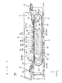
- Fig. 1 is a schematic sectional view principally showing a mechanical construction of a fixed head type image recording apparatus 100 for recording an image based on inkjet technology which is a form of an image recording apparatus according to a preferred embodiment of the present invention.
- Fig. 2 is a perspective view of principal parts of the image recording apparatus 100.
- An XYZ rectangular coordinate system such that a direction in which recording media RM are transported is defined as the positive X direction and a vertically upward direction is defined as the positive Z direction is additionally shown in Fig. 1 .
- the image recording apparatus 100 is an apparatus for recording an image on the recording media RM such as, for example, printing paper and the like in accordance with descriptions of previously provided image recording data (data about color density values of pixels constituting an image to be recorded).
- the image recording apparatus 100 is an inkjet printer for recording an image by ejecting inks of different colors (e.g., four colors: C (cyan), M (magenta), Y (yellow), and K (black)) corresponding to a plurality of (in Fig. 1 , four) inkjet heads 4H (41 to 44), respectively, from the inkjet heads 4H toward the recording media RM.
- At least two of the plurality of inkjet heads 4H may eject inks of the same color (e.g., white).
- An example of the recording medium RM used in this preferred embodiment includes, but is not limited to, typical printing paper (wood free paper).
- the recording media RM may be made of a material capable of accepting ink, such as a plastic film and the like.
- the image recording apparatus 100 principally includes: a supply part 2 for supplying the recording media RM from a pre-recording stocking part 10 for stocking therein the recording media RM to be subjected to image recording; a transport mechanism 3 for transporting the recording media RM along a predetermined transport path by using ten tables 20 each capable of holding a recording medium RM thereon; an image recording part 4 for ejecting inks from a multiplicity of inkjet nozzles provided at the lower end of each of the inkjet heads 4H (41 to 44) toward the recording media RM passing through the transport path; a discharge part 5 for discharging the recording media RM with an image recorded thereon from the transport path to place the recording media RM into a post-recording stocking part (not shown); a recording medium detection sensor 6 for detecting the presence or absence of the recording media RM on the tables 20 at a predetermined position of the transport path; a scanner 7 for photoelectrically reading the image formed on the recording media RM by the image recording part 4
- all of the inkjet heads 4H (the head 41 for black, the head 42 for cyan, the head 43 for magenta, and the head 44 for yellow) are fixedly provided in predetermined positions. Recording of an image is achieved by ejecting inks from the plurality of inkjet nozzles provided at the lower end of each of the inkjet heads 4H in synchronism with the travel of the recording media RM directly under each of the inkjet heads 4H.
- the plurality of inkjet nozzles in each of the inkjet heads 4H are disposed to eject ink at equal intervals within an image recording area along the width of the recording media RM (in the Y direction as viewed in Fig. 1 ) toward the recording media RM transported directly thereunder so that the image is recorded on the entire surface of each of the recording media RM.
- the arrangement of the plurality of inkjet nozzles may be determined as appropriate.
- the recording media RM are previously placed on or stocked in the pre-recording stocking part 10 provided in the supply part 2.
- the recording media RM placed on or stocked in the pre-recording stocking part 10 are attracted one by one from the top under suction by a supply sucker 13 not shown, and are sequentially supplied to a conveyor 11.
- the conveyor 11 transports the supplied recording media RM sequentially to the tables 20 provided in the transport mechanism 3.
- a supply control part 82 to be described later controls when to attract the recording media RM under suction by means of the supply sucker 13 in consideration for the time between the supply of the recording media RM to the conveyor 11 and the transfer of the recording medium RM to the tables 20.
- the ten tables 20 are arranged at fixed intervals on an endless track extending along endless guides 25 disposed on opposite side panels 33, and travels on the endless track along the guides 25.
- Each of the tables 20 is capable of holding a single recording medium RM thereon under suction through a suction hole 21.
- the recording medium RM supplied from the conveyor 11 to each of the tables 20 is transported on the transport path while being held thereon under suction through the suction hole 21.
- a vacuum fan 22 is provided under the transport path of the tables 20, and exhausts air to thereby allow the recording medium RM to be held on each of the tables 20 under suction through the suction hole 21.
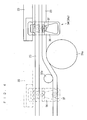
- Fig. 3 is a partial perspective view showing components related to the transport of the tables 20 in the transport mechanism 3 in further detail.
- Fig. 4 is a partial view showing the coupling between the tables 20 and a chain 23 in further detail. More specifically, each of the plurality of tables 20 includes coupling portions 34 (first coupling portions 34a and second coupling portions 34b) at the four corners thereof.
- the coupling portions 34 include guide receiving portions 35 (35a and 35b), respectively, for engagement with the guides 25.
- the guide receiving portions 35 enable each of the tables 20 to be guided along the guides 25 and to be transported circularly in the transport mechanism 3.
- each the first coupling portions 34a provided at the front as viewed in the direction of the travel is provided with a chain coupling portion 36 having a generally triangular hole.
- the chain coupling portion 36 of each of the tables 20 is brought into engagement with a coupling pin 37 provided on the chain 23, whereby each of the tables 20 is coupled to the chain 23 looped around a pair of sprockets 26 disposed on the side panels 33 while being spaced a predetermined distance apart from the chain 23, as indicated by solid lines in Fig. 4 .
- a sprocket 27 is disposed on a side of one of the sprockets 26, and is coupled to a driving sprocket 28 and a driven sprocket 29 with a chain 30.
- the driving sprocket 28 is provided so as to be rotated by driving a motor not shown. As the motor not shown is driven, the chain 23 looped around the pair of sprockets 26 accordingly moves around to move the tables 20 along the guides 25.
- the vertical position of the chain 23 is changed at some midpoint by combining a pair of sprockets 31 (31a and 31b) and a pair of sprockets 32 (32a and 32b) together.
- the chain coupling portion 36 and the coupling pin 37 are decoupled from each other past a location in which the sprocket 31a and the sprockets 32a are combined.
- the tables 20 are moved by linear motor mechanisms 24 from this location to a location in which the sprocket 31 b and the sprocket 32b are combined, while being guided by the guides 25,
- the linear motor mechanisms 24 are provided so as to enable a linear motor to transport the tables 20 at least during the recording of an image on the recording media RM.
- the linear motor mechanisms 24 are provided so as to be able to transport the tables 20 when the image recording part 4 records an image and when the scanner 7 reads an image. This is to enhance the accuracy of travel of the tables 20 (i.e., the accuracy of transport of the recording media RM) during the passage of the tables 20 directly under the image recording part 4 and the scanner 7.
- image recording errors ejection in improper positions
- a shift in the transport position of the recording media RM results in a shift in the image recording and reading positions.
- a section of the transport path in which the tables 20 are transported by the linear motor mechanisms 24 is also referred to hereinafter as a linear transport section.
- a maximum of three tables 20 are allowed to be present in the linear transport section at the same time.
- the transport mechanism 3 in the image recording apparatus 100 is provided with the five linear motor mechanisms 24.
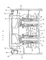
- Fig. 5 is a vertical sectional view showing principal parts of the transport mechanism 3 and for illustrating the construction of the linear motor mechanisms 24. For purposes of illustration, only four of the five linear motor mechanisms 24 are shown in Fig. 5 . The remaining linear motor mechanism 24 not shown is similar in construction to the four linear motor mechanisms 24 shown in Fig. 5 .
- the transport mechanism 3 may be provided with more than five linear motor mechanisms 24.
- Each of the linear motor mechanisms 24 includes a support plate 62 mounted upright on the main body of the image recording apparatus 100, a mobile base 63 disposed in opposed relation to the support plate 62, and a pair of linear guides 64 for coupling the mobile base 63 and the support plate 62 to each other and for horizontally movably guiding the mobile base 63 relative to the support plate 62.
- a stator 65 of the linear motor is fixed to the support plate 62, and a movable element 66 of the linear motor is fixed to the mobile base 63.
- the mobile base 63 provided with the movable element 66 is attachable to and detachable from a table 20 under the table 20. With the mobile base 63 provided with the movable element 66 being coupled to the table 20, the mobile base 63 and the table 20 are moved by changing the magnetic polarity of the stator 65 extending in the direction of the travel of the table 20.
- Each of the linear motor mechanisms 24 is provided with a movable element position detection sensor not shown for detecting where the movable element 66 is positioned in a corresponding one of the linear motor mechanisms 24.
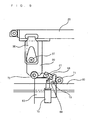
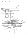
- Figs. 6 and 7 are side views showing the coupling mechanisms.
- Fig. 6 shows a coupling mechanism closer to the supply part 2
- Fig. 7 shows a coupling mechanism closer to the discharge part 5.
- Figs. 8 to 11 are illustrations showing the coupling and decoupling operations of the coupling mechanisms.
- a V-block 60 is attached to the lower surface of the table 2.
- a latch lever 68 pivotable about a shaft 67 is provided on the upper end of the mobile base 63 coupled to the movable element 66 of the linear motor as mentioned above.
- a cam follower 72 is provided on a first end of the latch lever 68. The cam follower 72 is configured to abut against a recessed portion of the V-block 60 to couple the latch lever 68 and the V-block 60 to each other.
- a cam follower 71 is provided on a second end of the latch lever 68.
- a lock lever 69 pivotable about a shaft 73 is provided on the upper end of the mobile base 63.
- a movable cam 80 extending in the direction of travel of the table 20 is provided under the above-mentioned cam follower 71.
- a pair of fixed cams 78 and 79 are provided on opposite ends of the movable cam 80 as viewed in the direction of the travel of the table 20.
- the movable cam 80 is coupled to the main body of the image recording apparatus 100 through pivotal levers 74.
- the movable cam 80 has a first end coupled through a link lever 75 to an air cylinder 76.
- the movable cam 80 has a second end coupled through a tension spring 177 to the main body of the image recording apparatus 100.
- the cam follower 71 is moved from on the movable cam 80 onto the fixed cam 79, as shown in Fig. 10 . Accordingly, the latch lever 68 is pivoted to disengage the cam follower 72 from the recessed portion of the V-block 60, thereby decoupling the cam follower 72 and the V-block 60 from each other. In this state, the table 20 and the movable element 66 of the linear motor mechanism 24 are decoupled from each other. Thereafter, the table 20 is transported again by the chain 23.
- the mobile base 63 returns from the second end position closer to the discharge part 5 to the first end position closer to the supply part 2.
- an air cylinder 70 is driven to pivot the lock lever 69 about the shaft 73, as shown in Fig. 11 .
- the latch lever 68 is fixed in a position such that the cam follower 72 is disengaged from the V-block 60.
- the mobile base 63 is moved from the second end position closer to the discharge part 5 to the first end position closer to the supply part 2.
- the table 20 After being transported by the linear motor mechanism 24, the table 20 is transported again by the chain 23.
- the table 20 moves to a predetermined position, and then transfers the recording medium RM held thereon under suction to the discharge part 5. Thereafter, the table 20 moves on the endless track along the guides 25, and is used again for the transport of another recording medium RM.
- the image recording apparatus 100 sufficiently ensures the accuracy of the holding position of the recording media RM on the tables 20, and the transport accuracy of the tables 20 during the image recording in the image recording part 4 and during the image reading in the scanner 7.
- the image recording apparatus 100 further includes a pre-processing agent ejection head 40 provided upstream from the inkjet heads 4H in the transport path and for applying a less visible (e.g., transparent) pre-processing agent prior to the ejection of ink from the inkjet heads 4H for the purpose of enhancing the fixability of ink ejected from the inkjet heads 4H.
- a pre-processing agent ejection head 40 provided upstream from the inkjet heads 4H in the transport path and for applying a less visible (e.g., transparent) pre-processing agent prior to the ejection of ink from the inkjet heads 4H for the purpose of enhancing the fixability of ink ejected from the inkjet heads 4H.
- a pre-processing agent ejection head 40 provided upstream from the inkjet heads 4H in the transport path and for applying a less visible (e.g., transparent) pre-processing agent prior to the ejection of ink from the inkjet heads 4H for
- the image recording apparatus 100 further includes heaters 45, 46, 47, 48 and 49 provided downstream from the pre-processing agent ejection head 40 and the inkjet heads 4H, respectively, and for blowing hot air onto the recording media RM.
- the heater 45 is provided for pre-heating
- the heaters 46, 47 and 48 are provided for intermediate heating
- the heater 49 is provided for main heating.
- the pre-processing agent ejection head 40, the inkjet heads 4H, the heaters 45 to 49 and the scanner 7 are movable by a drive mechanism not shown in a direction orthogonal to the transport direction of the recording media RM (in a direction perpendicular to the plane of Fig. 1 ). This enables the pre-processing agent ejection head 40, the inkjet heads 4H, the heaters 45 to 49 and the scanner 7 to reciprocatingly move between an image recording position opposed to the transport path of the recording media RM and a maintenance position not opposed to the transport path of the recording media RM.
- the pre-processing agent ejection head 40, the inkjet heads 4H, the heaters 45 to 49 and the scanner 7 are moved to the maintenance position. This removes obstructions on the transport path of the recording media RM to ensure the working space for the maintenance operation of the tables 20 and the like.
- the discharge part 5 includes a discharge drum 50.
- the discharge drum 50 separates the recording media RM from the tables 20 by winding the recording media RM around an outer peripheral portion thereof.
- an outlet passage switching mechanism 51 allow selection between the use of a first outlet passage 52 and the use of a second outlet passage 53 in accordance with a switching instruction from the controller 8.
- each of the first outlet passage 52 and the second outlet passage 53 includes a conveyor.
- the first outlet passage 52 and the second outlet passage 53 are provided with individual stocking parts (post-recording stocking parts), respectively, for stocking the recording media RM therein.
- the outlet passage switching mechanism 51 operates so that recording media RM subjected to a normal (or proper) image recording process are stocked in the stocking part through the first outlet passage 52, and other recording media
- the scanner 7 includes a linear CCD camera, and is adapted to photoelectrically read all or part (a patch and the like) of an image recorded on the recording media RM in response to a reading instruction from the controller 8. Typically, the scanner 7 reads an image recorded by the image recording part 4. In some cases, however, the scanner 7 reads an image without the image recording in the image recording part 4.
- the display and manipulation part 9 is a display device of a touch panel type. Specifically, with various menus and the like displayed on a screen of the display and manipulation part 9, an operator touches a predetermined position of the screen to perform an input manipulation.
- the display and manipulation part 9 is an integral unit composed of a display part and an input manipulation part as conceptual components.
- Such a configuration of the display and manipulation part 9 is not essential, but the display and manipulation part 9 may be configured, for example, such that a display part such as a liquid crystal display and an input manipulation part including a plurality of key buttons are provided separately.
- the recording medium detection sensor 6 is a reflective optical sensor provided downstream from the supply part 2 and upstream from the image recording part 4 over the transport path of the recording media RM, and detects whether there is a recording medium RM on each of the tables 20 or not.
- the recording medium detection sensor 6 directs light toward a table 20 reaching a position opposed thereto. Also, when there is no recording medium RM on the table 20, the recording medium detection sensor 6 receives light reflected from the table 20. When there is a recording medium RM on the table 20, the recording medium detection sensor 6 receives light reflected from the surface of the recording medium RM.
- the recording medium detection sensor 6 is not particularly limited to the reflective optical sensor if the recording medium detection sensor 6 is of the type which is capable of detecting whether there is a recording medium RM on the table 20 or not.
- Fig. 12 is a block diagram showing the construction of the controller 8.
- the controller 8 includes: a main control part 81 having a CPU 811, a ROM 812, a RAM 813 and the like and for effecting centralized control of the operation of the entire image recording apparatus 100 including the image recording process; the supply control part 82 for controlling the operation of the supply part 2; a transport control part 83 for controlling the operation of the transport mechanism 3; a recording medium detection control part 93 for controlling the operation of the recording medium detection sensor 6; an ejection control part 84 for controlling the operation of ejecting ink in the inkjet heads 4H (and also controlling the ejecting operation of the pre-processing agent ejection head 40 in the image recording apparatus 100); a discharge control part 85 for controlling the operation of the discharge part 5; a scanner control part 87 for controlling the operation of the scanner 7; a display and manipulation control part 89 for controlling the operation of the display and manipulation part 9; a malfunctioning linear motor mechanism detection part 90 for detecting a malfunction in the linear motor mechanisms 24; an unused linear motor mechanism determination part 91 for
- the malfunctioning linear motor mechanism detection part 90 detects a malfunction in the linear motor mechanisms 24. Specifically, when a position detection sensor provided in a linear motor mechanism 24 detects the improper return of the moveable element 66 to the first end position of the linear motor mechanism 24 closer to the supply part 2 or when the position of the movable element 66 in the linear motor mechanism 24 is not detected due to a failure of the position detection sensor, the malfunctioning linear motor mechanism detection part 90 detects the linear motor mechanism 24 as a malfunctioning linear motor mechanism.
- the malfunctioning linear motor mechanism detection part 90 may detect such a malfunction either before the image recording apparatus 100 starts the image recording process or continuously or intermittently while the image recording apparatus 100 performs the image recording process.
- the unused linear motor mechanism determination part 91 serves to determine a linear motor mechanism 24 which is not to be used for the transport of the tables 20.
- a linear motor mechanism 24 detected as a malfunctioning linear motor mechanism by the malfunctioning linear motor mechanism detection part 90 is determined as the linear motor mechanism 24 which is not to be used for the transport.
- the operator may manipulate the display and manipulation part 9 to selectively specify linear motor mechanisms 24 to be used for the transport.
- the operator may specify whether to stop driving the linear motor mechanism 24 determined as the linear motor mechanism which is not to be used for the transport or not. When the operator determines to stop driving the linear motor mechanism 24, the driving of the linear motor mechanism 24 is stopped under the control of the transport control part 83.
- the supply timing determination part 92 determining whether to provide an intermittent supply such that no recording medium RM is supplied to a specific table 20 when the supply part 2 supplies the recording media RM sequentially to the plurality of tables 20.
- the supply timing determination part 92 also performs the process of specifying a table 20 to which no recording medium RM is supplied and process of determining a supply timing so that no recording medium RM is supplied to the specific table 20.
- the process of determining the supply timing in the supply timing determination part 92 will be described later in detail.
- the supply control part 82 controls the operation of the supply sucker 13 so that no recording medium RM is attracted under suction, whereby no recording medium RM is supplied to only the specific table 20.
- the supply control part 82, the transport control part 83, the recording medium detection control part 93, the ejection control part 84, the discharge control part 85, the scanner control part 87, the display and manipulation control part 89, the malfunctioning linear motor mechanism detection part 90, the unused linear motor mechanism determination part 91 and the supply timing determination part 92 may be provided in the form of respective purpose-built control circuits, and may have a CPU, a ROM, a RAM and the like in a manner similar to the main control part 81. Further, the main control part 81 may also have the functions of the respective control parts.
- the controller 8 further includes a storage part 86 composed of, for example, a hard disk and the like.
- the storage part 86 stores therein a program PG executed in the CPU 811 to thereby perform various functions in the main control part 81, and various data related to the operation of the image recording apparatus 100.
- Examples of the data stored in the storage part 86 include image recording data D0 about descriptions of recording (color density values for respective pixel positions (XY addresses) described based on a CMYK color system) of an image to be recorded, a look-up table TB containing descriptions about a relationship (a tone reproduction curve) between the color density values and the amount of ink ejection for the individual inkjet nozzles, and SPM (screen pattern memory) data DS specifying how to eject ink to form pixels having a given color density value.
- the image recording data D0 may be held in the RAM 813.
- FIGs. 13 to 21 are schematic diagrams of the linear transport section in the image recording apparatus 100 as viewed in the positive Z direction of Fig. 1 for the purpose of illustrating the transport of the ten tables 20 by using the linear motor mechanisms 24.
- the direction of travel of the tables 20 in the linear transport section i.e. the direction of transport of the recording media RM, is leftward, i.e. from right to left, as viewed in Figs. 13 to 21 .
- reference numerals 24a, 24b, 24c, 24d and 24e are used to make a distinction between the five linear motor mechanisms 24, and the linear motor mechanisms 24a, 24b, 24c, 24d and 24e shall be arranged in the order named in the negative Y direction of Fig. 1 .
- Reference numerals 66a to 66e are used to designate the movable elements of the respective linear motor mechanisms 24a to 24e, and the movable elements 66a to 66e are schematically shown in Figs. 13 to 21 . Arrows in Figs. 13 to 21 denote the direction of the movement of the movable elements 66a to 66e.
- Reference numerals 20a to 20j are used to make a distinction between the ten tables 20.
- the table 20a is the table transported for the first time from a first end position of the linear transport section closer to the supply part 2 (the right-hand end position of the linear motor mechanisms 24a to 24e as viewed in Figs. 13 to 21 ) to a second end position thereof closer to the discharge part 5 (the left-hand end position of the linear motor mechanisms 24a to 24e as viewed in Figs. 13 to 21 ).
- the tables 20b, 20c, 20d, ... and 20j are the tables 20 transported following the table 20a to the second end position in the order named. Following the table 20j, the table 20a transported by the chain 23 along the endless track after the transport in the linear transport section reaches the first end position of the linear transport section closer to the supply part 2 again.
- Figs. 13 to 15 are diagrams for illustration of the transport of the ten tables 20a to 20j by using the five linear motor mechanisms 24a to 24e. This corresponds to an instance (a first case) in which no linear motor mechanisms 24 are determined by the unused linear motor mechanism determination part 91.
- the tables 20a, 20b and 20c are shown as coupled to the movable elements 66a, 66b and 66c, respectively, and transported from right to left as viewed in the figure.
- the movable element 66d is in a standby condition in the first end position of the linear transport section closer to the supply part 2, pending the table 20d to be transported next to the linear transport section by the linear motor mechanisms 24.
- the movable element 66e is moving, after finishing the transport of the table 20j having been executed immediately before the transport of the table 20a by the linear motor mechanisms 24, to return from the second end position of the linear motor mechanism 24e closer to the discharge part 5 to the first end position thereof closer to the supply part 2.
- Fig. 14 is a diagram showing the linear transport section after the movable element 66a finishes the transport of the table 20a with reference to Fig. 13 .
- the tables 20b, 20c and 20d are shown as coupled to the movable elements 66b, 66c and 66d, respectively, and transported in the order named as viewed from the second end position of the linear transport section closer to the discharge part 5.
- the movable elements 66a is moving to return to the first end position of the linear motor mechanism 24a closer to the supply part 2 after finishing the transport of the table 20a.
- the movable element 66e is in a standby condition in the first end position of the linear motor mechanism 24e closer to the supply part 2 pending the table 20e to be transported next.
- Fig. 15 is a diagram showing the linear transport section after the movable element 66b finishes the transport of the table 20b with reference to Fig. 14 .
- the tables 20c, 20d and 20e are shown as coupled to the movable elements 66c, 66d and 66e, respectively, and transported in the order named as viewed from the second end position of the linear transport section closer to the discharge part 5.
- the movable element 66b is moving to return to the first end position of the linear motor mechanism 24b closer to the supply part 2 after finishing the transport of the table 20b.
- the movable element 66a is in a standby condition in the first end position of the linear motor mechanism 24a closer to the supply part 2 pending the table 20f to be transported next.
- the five linear motor mechanisms 24a to 24e are used to transport the tables 20a to 20j sequentially to the linear transport section.
- Figs. 16 to 18 are diagrams for illustration of the transport of the ten tables 20a to 20j when, because one linear motor mechanism 24d included among the five linear motor mechanisms 24a to 24e malfunctions or for other reasons, the remaining four linear motor mechanisms 24 are used for the transport.
- Figs. 16 to 18 are diagrams illustrating an instance in which the linear motor mechanism 24d is determined to be unused for the transport by the unused linear motor mechanism determination part 91. This corresponds to an instance (a second case) in which the sum of the number of linear motor mechanisms 24 determined to be unused (in this case, one) and the number of tables transported at the same time (in this case, three) is less than the number of linear motor mechanisms 24 provided in the image recording apparatus 100 (in this case, five).
- the tables 20a, 20b and 20c are shown as coupled to the movable elements 66a, 66b and 66c, respectively, and transported from right to left as viewed in the figure.
- the movable element 66e is moving, after finishing the transport of the table 20j having been executed immediately before the transport of the table 20a by the linear motor mechanisms 24, to return from the second end position of the linear motor mechanism 24e closer to the discharge part 5 to the first end position thereof closer to the supply part 2.
- the movable element 66d (and the linear motor mechanism 24d) is not used for the transport, as mentioned above.
- Fig. 17 is a diagram showing the linear transport section after the movable element 66a finishes the transport of the table 20a with reference to Fig. 16 .
- the tables 20b and 20c are shown as coupled to the movable elements 66b and 66c, respectively, and transported in the order named as viewed from the second end position of the linear transport section closer to the discharge part 5. Since the linear motor mechanism 24d is determined to be unused by the unused linear motor mechanism determination part 91, the table 20d is coupled to the movable element 66e provided in the linear motor mechanism 24e and transported thereby.
- the movable element 66a is moving to return to the first end position of the linear motor mechanism 24a closer to the supply part 2 after finishing the transport of the table 20a.
- Fig. 18 is a diagram showing the linear transport section after the movable element 66b finishes the transport of the table 20b with reference to Fig. 17 .
- the tables 20c, 20d and 20e are shown as coupled to the movable elements 66c, 66e and 66a, respectively, and transported in the order named as viewed from the second end position of the linear transport section closer to the discharge part 5.
- the movable element 66b is moving to return to the first end position of the linear motor mechanism 24b closer to the supply part 2 after finishing the transport of the table 20b.
- the second case provides a throughput similar to that of the first case to achieve the image recording although the linear motor mechanism 24 determined to be unused is present.
- Figs. 19 to 21 are diagrams for illustration of the transport of the ten tables 20a to 20j when, because two linear motor mechanisms 24c and 24d included among the five linear motor mechanisms 24a to 24e malfunction or for other reasons, the remaining three linear motor mechanisms 24 are used for the transport.
- Figs. 19 to 21 are diagrams illustrating an instance in which the linear motor mechanisms 24c and 24d are determined to be unused for the transport by the unused linear motor mechanism determination part 91.
- the tables 20a, 20b and 20c are shown as coupled to the movable elements 66a, 66b and 66e, respectively, and transported from right to left as viewed in the figure.
- the movable element 66c (and the linear motor mechanism 24c) and the movable element 66d (and the linear motor mechanism 24d) are not used for the transport, as mentioned above.
- Fig. 20 is a diagram showing the linear transport section after the movable element 66a finishes the transport of the table 20a with reference to Fig. 19 .
- the tables 20b and 20c are shown as coupled to the movable elements 66b and 66e, respectively, and transported in the order named as viewed from the second end position of the linear transport section closer to the discharge part 5.
- the movable element 66a is moving to return to the first end position of the linear motor mechanism 24a closer to the supply part 2 after finishing the transport of the table 20a.
- the chain 23 is used in place of the linear motor mechanisms 24 to transport the table 20d in this preferred embodiment.
- the chain 23 is used as an alternative to transport a table 20 which cannot be transported by the linear motor mechanisms 24 in the linear transport section because of the presence of the linear motor mechanism 24 determined to be unused.
- Fig. 21 is a diagram showing the linear transport section after the movable element 66b finishes the transport of the table 20b with reference to Fig. 20 .
- the tables 20c and 20e are shown as coupled to the movable elements 66e and 66a, respectively, and transported in the order named as viewed from the second end position of the linear transport section closer to the discharge part 5.
- the table 20d is shown as transported by the chain 23.
- the movable element 66b is moving to return to the first end position of the linear motor mechanism 24b closer to the supply part 2 after finishing the transport of the table 20b.
- one of the tables 20 is required to be transported before any of the movable elements 66 returns.
- this table 20 is not transported by the linear motor mechanisms 24, but the chain 23 is used as an alternative to transport this table 20.
- the image recording apparatus 100 is adapted to transport the tables 20 in a manner to be described below.
- the linear motor mechanisms 24 except the linear motor mechanism(s) 24 determined to be unused are used to transport the tables 20.
- the chain 23 is used as an alternative for the transport.
- this preferred embodiment suppresses the reduction in productivity, as compared with the complete stop of the image recording apparatus 100.
- the supply timing of the recording media RM from the supply part 2 will be described in detail.
- the image recording apparatus 100 is adapted so that no recording medium RM is supplied from the supply part 2 to the table 20 transported by the chain 23 as an alternative. In other words, the intermittent supply of the recording media RM is provided.
- Fig. 22 is a flow diagram showing the process of determining the supply timing of the recording media RM, i.e. when to supply the recording media RM, from the supply part 2.
- the unused linear motor mechanism determination part 91 determines a linear motor mechanism 24 to be unused for the transport (in Step S1).
- the linear motor mechanism 24 determined to be unused includes a linear motor mechanism 24 specified arbitrarily by an operator in addition to a linear motor mechanism 24 detected by the malfunctioning linear motor mechanism detection part 90 as a malfunctioning linear motor mechanism.
- linear setting data D about descriptions of information indicating whether each of the linear motor mechanisms 24a to 24e is to be used for the transport or not is generated in the unused linear motor mechanism determination part 91 (in Step S2).
- the 1-bit data Da to De are those corresponding to the linear motor mechanisms 24a to 24e, respectively.
- the value of the corresponding 1-bit data is "0.”
- the value of the corresponding 1-bit data is "1.”
- the value of the corresponding 1-bit data may be "0" when each of the linear motor mechanisms 24 is determined to be used, and be “1” when each of the linear motor mechanisms 24 is determined to be unused.
- Step S3 whether to provide the intermittent supply or not is judged in the supply timing determination part 92, based on the linear setting data D (in Step S3). Whether to provide the intermittent supply or not is determined by whether there is a table 20 to be transported by the chain 23 or not. Specifically, when x + y ⁇ z, it is judged to be necessary to provide the intermittent supply, and the process in Step S4 is subsequently performed. When x + y ⁇ z in the linear transport section, it is not judged to be necessary to provide the intermittent supply, and the process in Step S6 is subsequently performed.
- the supply timing determination part 92 determines the supply timing of the recording media RM so as to provide the intermittent supply (in Step S4). Specifically, when the ten tables 20 to be sequentially transported are to be transported by the chain 23 as an alternative is determined in accordance with the information described in the linear setting data D and specifying the use or non-use of the linear motor mechanisms 24a to 24e. In accordance with such a corresponding relationship, a determination is made as to whether the supply part 2 supplies a recording medium RM to each of the tables 20 or not (i.e., whether the supply part 2 provides the intermittent supply or not).
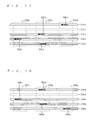
- Fig. 23 is a view for illustration of the supply timing of the recording media RM which is determined by the supply timing determination part 92 when the linear motor mechanisms 24c and 24d are to be unused (in corresponding relation to the third case).
- a corresponding relationship between the tables 20a to 20j and the linear motor mechanisms 24a to 24e (i.e., the movable elements 66a to 66e) for transporting the tables 20a to 20j is shown in Fig. 23 .
- Fig. 23 are shown the liner motor mechanisms 24a to 24e or the chain 23 responsible for the transport of the tables 20a to 20j in the linear transport section.
- the tables 20 transported by the chain 23 are diagonally shaded in Fig. 23 .
- the linear motor mechanism 24 to be unused is not determined, the table 20a, 20b, 20c, 20d, 20e, 20f, ... (repeated) shall be transported sequentially by the linear motor mechanisms 24a, 24b, 24c, 24d, 24e, 24a, ... (repeated).
- the order in which the tables 20a to 20j are transported in the linear transport section is shown from the upper left in Fig. 23 .
- the table 20a is initially transported by the movable element 66a of the linear motor mechanism 24a, and the tables 20b is then transported by the movable element 66b of the linear motor mechanism 24b, as sequentially shown in Figs. 19 to 21 .
- the table 20c to be transported next is transported by the movable element 66e of the linear motor mechanism 24e because the originally scheduled linear motor mechanism 24c and also the linear motor mechanism 24d are to be unused.
- the table 20d is transported to the first end position of the linear transport section closer to the supply part 2 and serves as the next table to be transported in the linear transport section. At this point, however, there is no linear motor mechanism 24 which can transport the table 20d. Thus, the table 20d is transported by the chain 23.
- the tables 20e; 20f and 20g are transported by using the linear motor mechanisms 24a, 24b and 24e, respectively, and the table 20h is transported by the chain 23 in a similar manner.
- the tables 20i, 20j and 20a are transported by using the linear motor mechanisms 24a, 24b and 24e, respectively, and the table 20b is transported by the chain 23.
- the supply timing determination part 92 determines the supply timing of the recording media RM from the supply part 2 so that no recording medium RM is supplied to every fourth table 20 as mentioned above.
- the supply control part 82 controls the supply part 2 so that the supply part 2 supplies the recording media RM to the tables 20 in accordance with such supply timing.
- the recording medium detection control part 93 makes setting so as to exclude a table 20 to which no recording medium RM is supplied because of the transport by the chain 23 as an alternative from the tables 20 to be detected by the recording medium detection sensor 6 (in Step S5). This intentionally excludes the table 20 to which no recording medium RM is supplied and which is transported by the chain 23 as an alternative from the tables 20 to be subjected to the error detection in the recording medium detection sensor 6 in the image recording apparatus 100.
- Step S6 the image recording is performed (in Step S6).
- the transport control part 83 places the transport mechanism 3 in operation.
- the supply part 2 supplies the recording media RM to the tables 20 under the control of the supply control part 82, and the inkjet heads 4H eject ink under the control of the ejection control part 84, whereby the image recording is achieved.
- the intermittent supply of the recording media RM is not provided, the recording media RM are transported to all of the tables 20.
- the intermittent supply of the recording media RM is provided, the intermittent supply is provided in accordance with the supply timing determined in Step S4.
- the supply control part 82 effects control so that the supply sucker 13 attracts under suction no recording medium RM placed on or stocked in the pre-recording stocking part 10.
- the image recording apparatus 100 is capable of determining at least one of the linear motor mechanisms 24 to be unused for the transport to record an image without using the determined linear motor mechanism 24. Additionally, when the sum of the number of linear motor mechanisms 24 determined to be unused and the number of tables 20 transported at the same time in the linear transport section is less than the number of linear motor mechanisms 24 provided in the image recording apparatus 100, the linear motor mechanisms 24 except the linear motor mechanism 24 determined to be unused are used to transport the tables 20. When the above-mentioned sum is not less than the number of linear motor mechanisms 24 provided in the image recording apparatus 100, the chain 23 is used as an alternative for the transport.
- the image recording apparatus 100 is capable of achieving the image recording although the throughput thereof decreases, to thereby suppress the reduction in productivity, as compared with the complete stop of the image recording apparatus 100.
- the supply part 2 is configured to supply no recording medium RM to the table 20 which cannot be transported by the linear motor mechanisms 24 but is required to be transported by the chain 23 as an alternative in the linear transport section.
- the image recording apparatus 100 is capable of maintaining the accuracy of image recording as high as that obtained when there is no linear motor mechanism 24 determined to be unused.
- the image recording apparatus 100 is described as an inkjet printer in the above-mentioned preferred embodiment, the application of the present invention is not limited to an apparatus for recording an image based on inkjet technology.
- the transport mechanism 3 includes the ten tables 20 in the above description, the number of tables 20 provided in the transport mechanism 3 is not limited to ten.
- the transport mechanism 3 includes the five linear motor mechanisms 24 in the above description, the number of linear motor mechanisms 24 provided in the transport mechanism 3 is not limited to five.
- the order in which the plurality of linear motor mechanisms 24 are used to transport the tables 20 is not limited to that shown in Figs. 13 to 21 .
- linear motor mechanisms 24 are capable of transporting a maximum of three tables 20 at the same time in the above description, the maximum number of tables 20 transported by the linear motor mechanisms 24 at the same time is not limited to three.
Landscapes
- Ink Jet (AREA)
- Handling Of Sheets (AREA)
- Delivering By Means Of Belts And Rollers (AREA)
Claims (5)
- Eine Bildaufzeichnungsvorrichtung mit:a) einem Bildaufzeichnungsteil (4) zum Aufzeichnen eines Bildes auf einem Aufzeichnungsmedium (RM); undb) eine Aufzeichnungsmediumtransporteinrichtung zum Transportieren des Aufzeichnungsmediums (RM), das in einem vorbestimmten Lager (10) gelagert ist,
wobei die Aufzeichnungsmediumtransporteinrichtung aufweistb-1) eine Mehrzahl von Tischen (20) zum Halten des Aufzeichnungsmediums (RM) auf diesen,b-2) ein Zuführteil (2) zum Zuführen des Aufzeichnungsmediums (RM) zu jedem aus der Mehrzahl von Tischen (20),b-3) eine Mehrzahl von Linearmotormechanismen (24) zum Transportieren der Mehrzahl von Tischen (20) in einen ersten Transportabschnitt mit wenigstens einem Bereich, in dem das Bildaufzeichnungsteil (4) ein Bild auf dem Aufzeichnungsmedium (RM) aufzeichnet,b-4) einem Endlostransportmechanismus zum Transportieren der Mehrzahl von Tischen (20) in wenigstens einen an den ersten Transportabschnitt angrenzenden zweiten Transportabschnitt, der dazu in der Lage ist, die Mehrzahl von Tischen (20) in den ersten Transportabschnitt zu transportieren, undb-5) einem Bestimmungsteil zum Bestimmen eines nicht verwendeten Linearmotormechanismus (24) der für den Transport der Mehrzahl von Tischen (20) aus der Mehrzahl von Linearmotormechanismen (24) nicht verwendet wird,
wobei die Mehrzahl von Linearmotormechanismen (24) und der Endlostransportmechanismus derart ausgebildet ist, dass die Mehrzahl von Tischen (20) sequenziell und zirkular für den Transport in den ersten Transportabschnitt verwendet werden,
wobei dann, wenn der nicht verwendete Linearmotormechanismus (24) nicht bestimmt ist, alle aus der Mehrzahl von den Linearmotormechanismen (24) für den Transport der Mehrzahl von Tischen (20) in den ersten Transportabschnitt verwendet werden, und
wobei dann, wenn der nicht verwendete Linearmotormechanismus (24) bestimmt ist, der Endlostransportmechanismus als eine Alternative zum Transportieren wenigstens eines aus der Mehrzahl von Tischen (20) verwendet wird, der in den ersten Transportabschnitt zu transportieren, aber durch keinen aus der Mehrzahl von Linearmotormechanismen (24) transportiert werden kann. - Eine Bildaufzeichnungsvorrichtung nach Anspruch 1, wobei:die Aufzeichnungsmediumtransporteinrichtung weiter aufweistb-6) ein Zufuhrzeitbestimmungsteil (92) zum Bestimmen der Zufuhrzeit, die angibt, wann das Aufzeichnungsmedium (RM) von dem Zufuhrteil (2) in Übereinstimmung mit dem Transportzustand der Mehrzahl von Tischen (20) zuzuführen ist, wobei das Zufuhrzeitbestimmungsteil die Zufuhrzeit derart bestimmt, dass dann, wenn ein alternativer Transporttisch (20) von dem Endlostransportmechanismus in den ersten Transportabschnitt zu transportieren ist als eine Alternative zu der Mehrzahl von Tischen (20) vorhanden ist, das Aufzeichnungsmedium (RM) nicht von dem Zufuhrteil (2) zu dem alternativen Transporttisch (20) zugeführt wird;der Transportteil (2) das Aufzeichnungsmedium (RM) zu der Mehrzahl von Tischen (20) basierend auf der Zufuhrzeit, die von dem Zufuhrzeitbestimmungsteil bestimmt ist, fördert,
- Die Bildaufzeichnungsvorrichtung nach Anspruch 2, wobei die Aufzeichnungsmediumtransporteinrichtung weiter aufweistb-7) einen Aufzeichnungsmediumerkennungssensor (6) zum Erkennen, ob die Mehrzahl von Tischen (20), die jeweils das Aufzeichnungsmedium (RM) auf diesem halten, in einem Transportweg des Aufzeichnungsmediums (RM) vorhanden sind oder nicht, wobei der Aufzeichnungserkennungssensor (6) den alternativen Transporttisch (20) aus der Mehrzahl von den zu erkennenden Tischen (20) ausschließt.
- Die Bildaufzeichnungsvorrichtung nach Anspruch 1, wobei der nicht verwendete Linearmotormechanismus (20) seinen Betrieb in Übereinstimmung mit der Bestimmung des Bestimmungsteils für den nicht verwendeten Linearmotormechanismus (24) stoppt.
- Die Bildaufzeichnungsvorrichtung nach Anspruch 1, wobei:die Anzahl der Linearmotormechanismen (24), die in dem Aufzeichnungsmedium wegen der Aufzeichnungsmediumtransporteinrichtung vorgesehen sind, um wenigstens zwei größer ist als eine simultane Transporttischzahl, die die Anzahl der Tische (20) angibt, die von den Tischen (20) vorhanden ist und zu dem selben Zeitpunkt in den ersten Transportabschnitt transportiert werden;die Mehrzahl von Linearmotormechanismen (24) mit Ausnahme des nicht verwendeten Linearmotormechanismus (24) zum Transportieren der Mehrzahl von Tischen (20) in der ersten Transportrichtung verwendet werden, wenn die Summe der Anzahl der nicht verwendeten Linearmotormechanismen (24) und die Zahl der simultanen Transporttische kleiner ist als die Anzahl der Linearmotormechanismen (24), die in der ersten Aufzeichnungsmediumtransporteinrichtung vorgesehen sind;der Endlostransportmechanismus als eine Alternative zum Transport nur dann verwendet wird, wenn die Summe der Anzahl der nicht verwendeten Linearmotormechanismen (24) unddie Zahl der simultanen Transporttische nicht kleiner ist als die Anzahl der Linearmotormechanismen (24), die in der Aufzeichnungsmediumtransporteinrichtung vorgesehen sind.
Applications Claiming Priority (1)
| Application Number | Priority Date | Filing Date | Title |
|---|---|---|---|
| JP2008139766A JP5037431B2 (ja) | 2008-05-28 | 2008-05-28 | 画像記録装置における記録媒体搬送装置 |
Publications (2)
| Publication Number | Publication Date |
|---|---|
| EP2127889A1 EP2127889A1 (de) | 2009-12-02 |
| EP2127889B1 true EP2127889B1 (de) | 2011-05-25 |
Family
ID=40566859
Family Applications (1)
| Application Number | Title | Priority Date | Filing Date |
|---|---|---|---|
| EP09003226A Not-in-force EP2127889B1 (de) | 2008-05-28 | 2009-03-05 | Aufzeichnungsmedientransportvorrichtung in Bildaufzeichnungsvorrichtung |
Country Status (4)
| Country | Link |
|---|---|
| US (1) | US7900920B2 (de) |
| EP (1) | EP2127889B1 (de) |
| JP (1) | JP5037431B2 (de) |
| AT (1) | ATE510699T1 (de) |
Families Citing this family (12)
| Publication number | Priority date | Publication date | Assignee | Title |
|---|---|---|---|---|
| JP5037430B2 (ja) * | 2008-05-28 | 2012-09-26 | 大日本スクリーン製造株式会社 | 画像記録装置における搬送装置、画像記録装置の搬送装置における搬送速度補正方法 |
| IT1399373B1 (it) * | 2010-04-09 | 2013-04-16 | Cabur S R L | Stampante e struttura a tabella per il supporto e l'alimentazione di gruppi di prodotti in tale stampante |
| US9421794B2 (en) | 2012-05-21 | 2016-08-23 | CED Integrated Solutions, Inc. | Fluid application system and method |
| EP2803493A1 (de) * | 2013-05-15 | 2014-11-19 | Agfa Graphics Nv | Bandstufen-Fördersystem |
| US9365350B2 (en) * | 2014-10-07 | 2016-06-14 | Bernard J. Sherwood | Inverted vacuum belt conveyor system |
| DE102015204215A1 (de) | 2015-03-10 | 2016-09-15 | Heidelberger Druckmaschinen Ag | Druckmaschine mit Transportsystem |
| DE102016201762A1 (de) | 2015-03-12 | 2016-09-15 | Heidelberger Druckmaschinen Ag | Bogendruckmaschine mit koppelbaren Transporttischen |
| EP3124263B1 (de) | 2015-07-31 | 2018-05-16 | HP Scitex Ltd | Druckmedientransportvorrichtung |
| DE102016223748A1 (de) | 2016-01-18 | 2017-07-20 | Heidelberger Druckmaschinen Ag | Linearantrieb für Tablets in Inkjetdruckmaschinen |
| DE102017211647A1 (de) * | 2017-07-07 | 2019-01-10 | Heidelberger Druckmaschinen Ag | Vorrichtung zum Transport von zu bedruckenden Objekten |
| JP7354572B2 (ja) * | 2019-04-10 | 2023-10-03 | セイコーエプソン株式会社 | 記録装置 |
| CN112193871B (zh) * | 2020-10-26 | 2022-11-11 | 深圳弘锐精密数码喷印设备有限公司 | 输送装置、输送系统及打印设备 |
Family Cites Families (11)
| Publication number | Priority date | Publication date | Assignee | Title |
|---|---|---|---|---|
| US4719721A (en) * | 1986-12-18 | 1988-01-19 | Timesavers, Inc. | Conveyor bed assembly and vacuum platen |
| JPH0280269A (ja) | 1988-09-17 | 1990-03-20 | Canon Inc | レジストレーション補正装置 |
| JP2736989B2 (ja) | 1989-01-13 | 1998-04-08 | キヤノン株式会社 | 画像記録装置 |
| JP2891796B2 (ja) | 1990-04-17 | 1999-05-17 | キヤノン株式会社 | 被記録材を搬送するための搬送装置、および、その搬送装置を備える記録装置 |
| US6230876B1 (en) * | 1999-02-22 | 2001-05-15 | Joseph J. Gilberti | Indexing vacuum table |
| US7118103B2 (en) * | 2003-04-14 | 2006-10-10 | Heidelberger Druckmaschinen Ag | Device for conveying sheets through a printing machine |
| JP4729846B2 (ja) | 2003-10-30 | 2011-07-20 | 富士ゼロックス株式会社 | 記録装置 |
| JP4219264B2 (ja) | 2003-12-24 | 2009-02-04 | 三洋電機株式会社 | 光起電力装置 |
| JP2006224039A (ja) * | 2005-02-21 | 2006-08-31 | Dainippon Printing Co Ltd | パターン形成装置、パターニング方法、基板処理装置、基板処理方法 |
| EP1721749B1 (de) * | 2005-05-09 | 2010-07-28 | Agfa Graphics N.V. | Transportvorrichtung für ein Aufzeichnungsmedium eines digitalen Druckers |
| EP2106916B1 (de) * | 2008-03-31 | 2011-05-04 | Dainippon Screen Mfg., Co., Ltd. | Bildaufzeichnungsvorrichtung |
-
2008
- 2008-05-28 JP JP2008139766A patent/JP5037431B2/ja not_active Expired - Fee Related
-
2009
- 2009-03-05 EP EP09003226A patent/EP2127889B1/de not_active Not-in-force
- 2009-03-05 AT AT09003226T patent/ATE510699T1/de not_active IP Right Cessation
- 2009-03-06 US US12/399,245 patent/US7900920B2/en not_active Expired - Fee Related
Also Published As
| Publication number | Publication date |
|---|---|
| JP5037431B2 (ja) | 2012-09-26 |
| ATE510699T1 (de) | 2011-06-15 |
| US7900920B2 (en) | 2011-03-08 |
| US20090295080A1 (en) | 2009-12-03 |
| JP2009285948A (ja) | 2009-12-10 |
| EP2127889A1 (de) | 2009-12-02 |
Similar Documents
| Publication | Publication Date | Title |
|---|---|---|
| US7900920B2 (en) | Recording medium transport device in image recording apparatus | |
| US8226201B2 (en) | Image recording apparatus and method of detecting ejection failure in pre-processing agent ejection nozzles in image recording apparatus | |
| US7708398B2 (en) | Printing apparatus and printing method | |
| JP2008179086A (ja) | プリンタ装置、着脱方法、プリンタ用カートリッジおよびインクリボン体 | |
| EP3798011B1 (de) | Druckvorrichtung, verfahren zur steuerung davon und speichermedium | |
| CN108274896A (zh) | 喷墨记录装置 | |
| JP4818133B2 (ja) | 印刷装置 | |
| US5315404A (en) | Image processing method and apparatus for processing an image signal in each of a plurality of processing modes | |
| JP2006130857A (ja) | 記録装置 | |
| JP2003136791A (ja) | インクジェットプリンタ | |
| JP2009083351A (ja) | インクジェット記録装置 | |
| EP2127893B1 (de) | Transportvorrichtung für eine Bildaufzeichnungsvorrichtung und Verfahren zum Korrigieren der Transportgeschwindigkeit in einer Transportvorrichtung für eine Bildaufzeichnungsvorrichtung | |
| JP4952702B2 (ja) | 液体吐出装置 | |
| JP2021126890A (ja) | 画像形成装置 | |
| JP2012061790A (ja) | 媒体処理装置、媒体処理装置の制御方法、及び、プログラム | |
| JP2005305700A (ja) | 印刷搬送システム | |
| JP5075737B2 (ja) | 画像記録装置、および画像記録装置における記録予定位置調整方法 | |
| JP2019107904A (ja) | インクジェット記録装置及びインクジェット記録方法 | |
| JP4352740B2 (ja) | インクジェットプリンタ | |
| JP5799491B2 (ja) | 記録装置、記録装置の制御方法、及び、プログラム | |
| JP2000006491A (ja) | 記録装置および被記録媒体 | |
| JP2003266803A (ja) | 画像記録装置 | |
| JP2021066131A (ja) | インクジェット記録装置 | |
| JP2000296647A (ja) | 記録方法および記録装置 | |
| JPH10226098A (ja) | 記録方法および記録装置 |
Legal Events
| Date | Code | Title | Description |
|---|---|---|---|
| PUAI | Public reference made under article 153(3) epc to a published international application that has entered the european phase |
Free format text: ORIGINAL CODE: 0009012 |
|
| 17P | Request for examination filed |
Effective date: 20091008 |
|
| AK | Designated contracting states |
Kind code of ref document: A1 Designated state(s): AT BE BG CH CY CZ DE DK EE ES FI FR GB GR HR HU IE IS IT LI LT LU LV MC MK MT NL NO PL PT RO SE SI SK TR |
|
| AX | Request for extension of the european patent |
Extension state: AL BA RS |
|
| AKX | Designation fees paid |
Designated state(s): AT BE BG CH CY CZ DE DK EE ES FI FR GB GR HR HU IE IS IT LI LT LU LV MC MK MT NL NO PL PT RO SE SI SK TR |
|
| GRAP | Despatch of communication of intention to grant a patent |
Free format text: ORIGINAL CODE: EPIDOSNIGR1 |
|
| GRAS | Grant fee paid |
Free format text: ORIGINAL CODE: EPIDOSNIGR3 |
|
| GRAA | (expected) grant |
Free format text: ORIGINAL CODE: 0009210 |
|
| AK | Designated contracting states |
Kind code of ref document: B1 Designated state(s): AT BE BG CH CY CZ DE DK EE ES FI FR GB GR HR HU IE IS IT LI LT LU LV MC MK MT NL NO PL PT RO SE SI SK TR |
|
| REG | Reference to a national code |
Ref country code: GB Ref legal event code: FG4D |
|
| REG | Reference to a national code |
Ref country code: CH Ref legal event code: EP |
|
| REG | Reference to a national code |
Ref country code: IE Ref legal event code: FG4D |
|
| REG | Reference to a national code |
Ref country code: DE Ref legal event code: R096 Ref document number: 602009001333 Country of ref document: DE Effective date: 20110707 |
|
| REG | Reference to a national code |
Ref country code: NL Ref legal event code: VDEP Effective date: 20110525 |
|
| PG25 | Lapsed in a contracting state [announced via postgrant information from national office to epo] |
Ref country code: LT Free format text: LAPSE BECAUSE OF FAILURE TO SUBMIT A TRANSLATION OF THE DESCRIPTION OR TO PAY THE FEE WITHIN THE PRESCRIBED TIME-LIMIT Effective date: 20110525 Ref country code: HR Free format text: LAPSE BECAUSE OF FAILURE TO SUBMIT A TRANSLATION OF THE DESCRIPTION OR TO PAY THE FEE WITHIN THE PRESCRIBED TIME-LIMIT Effective date: 20110525 Ref country code: SE Free format text: LAPSE BECAUSE OF FAILURE TO SUBMIT A TRANSLATION OF THE DESCRIPTION OR TO PAY THE FEE WITHIN THE PRESCRIBED TIME-LIMIT Effective date: 20110525 Ref country code: NO Free format text: LAPSE BECAUSE OF FAILURE TO SUBMIT A TRANSLATION OF THE DESCRIPTION OR TO PAY THE FEE WITHIN THE PRESCRIBED TIME-LIMIT Effective date: 20110825 Ref country code: PT Free format text: LAPSE BECAUSE OF FAILURE TO SUBMIT A TRANSLATION OF THE DESCRIPTION OR TO PAY THE FEE WITHIN THE PRESCRIBED TIME-LIMIT Effective date: 20110926 |
|
| PG25 | Lapsed in a contracting state [announced via postgrant information from national office to epo] |
Ref country code: AT Free format text: LAPSE BECAUSE OF FAILURE TO SUBMIT A TRANSLATION OF THE DESCRIPTION OR TO PAY THE FEE WITHIN THE PRESCRIBED TIME-LIMIT Effective date: 20110525 Ref country code: BE Free format text: LAPSE BECAUSE OF FAILURE TO SUBMIT A TRANSLATION OF THE DESCRIPTION OR TO PAY THE FEE WITHIN THE PRESCRIBED TIME-LIMIT Effective date: 20110525 Ref country code: SI Free format text: LAPSE BECAUSE OF FAILURE TO SUBMIT A TRANSLATION OF THE DESCRIPTION OR TO PAY THE FEE WITHIN THE PRESCRIBED TIME-LIMIT Effective date: 20110525 Ref country code: FI Free format text: LAPSE BECAUSE OF FAILURE TO SUBMIT A TRANSLATION OF THE DESCRIPTION OR TO PAY THE FEE WITHIN THE PRESCRIBED TIME-LIMIT Effective date: 20110525 Ref country code: ES Free format text: LAPSE BECAUSE OF FAILURE TO SUBMIT A TRANSLATION OF THE DESCRIPTION OR TO PAY THE FEE WITHIN THE PRESCRIBED TIME-LIMIT Effective date: 20110905 Ref country code: IS Free format text: LAPSE BECAUSE OF FAILURE TO SUBMIT A TRANSLATION OF THE DESCRIPTION OR TO PAY THE FEE WITHIN THE PRESCRIBED TIME-LIMIT Effective date: 20110925 Ref country code: CY Free format text: LAPSE BECAUSE OF FAILURE TO SUBMIT A TRANSLATION OF THE DESCRIPTION OR TO PAY THE FEE WITHIN THE PRESCRIBED TIME-LIMIT Effective date: 20110525 Ref country code: LV Free format text: LAPSE BECAUSE OF FAILURE TO SUBMIT A TRANSLATION OF THE DESCRIPTION OR TO PAY THE FEE WITHIN THE PRESCRIBED TIME-LIMIT Effective date: 20110525 Ref country code: GR Free format text: LAPSE BECAUSE OF FAILURE TO SUBMIT A TRANSLATION OF THE DESCRIPTION OR TO PAY THE FEE WITHIN THE PRESCRIBED TIME-LIMIT Effective date: 20110826 |
|
| PG25 | Lapsed in a contracting state [announced via postgrant information from national office to epo] |
Ref country code: NL Free format text: LAPSE BECAUSE OF FAILURE TO SUBMIT A TRANSLATION OF THE DESCRIPTION OR TO PAY THE FEE WITHIN THE PRESCRIBED TIME-LIMIT Effective date: 20110525 |
|
| PG25 | Lapsed in a contracting state [announced via postgrant information from national office to epo] |
Ref country code: EE Free format text: LAPSE BECAUSE OF FAILURE TO SUBMIT A TRANSLATION OF THE DESCRIPTION OR TO PAY THE FEE WITHIN THE PRESCRIBED TIME-LIMIT Effective date: 20110525 Ref country code: CZ Free format text: LAPSE BECAUSE OF FAILURE TO SUBMIT A TRANSLATION OF THE DESCRIPTION OR TO PAY THE FEE WITHIN THE PRESCRIBED TIME-LIMIT Effective date: 20110525 |
|
| PG25 | Lapsed in a contracting state [announced via postgrant information from national office to epo] |
Ref country code: DK Free format text: LAPSE BECAUSE OF FAILURE TO SUBMIT A TRANSLATION OF THE DESCRIPTION OR TO PAY THE FEE WITHIN THE PRESCRIBED TIME-LIMIT Effective date: 20110525 Ref country code: PL Free format text: LAPSE BECAUSE OF FAILURE TO SUBMIT A TRANSLATION OF THE DESCRIPTION OR TO PAY THE FEE WITHIN THE PRESCRIBED TIME-LIMIT Effective date: 20110525 Ref country code: SK Free format text: LAPSE BECAUSE OF FAILURE TO SUBMIT A TRANSLATION OF THE DESCRIPTION OR TO PAY THE FEE WITHIN THE PRESCRIBED TIME-LIMIT Effective date: 20110525 Ref country code: RO Free format text: LAPSE BECAUSE OF FAILURE TO SUBMIT A TRANSLATION OF THE DESCRIPTION OR TO PAY THE FEE WITHIN THE PRESCRIBED TIME-LIMIT Effective date: 20110525 |
|
| PLBE | No opposition filed within time limit |
Free format text: ORIGINAL CODE: 0009261 |
|
| STAA | Information on the status of an ep patent application or granted ep patent |
Free format text: STATUS: NO OPPOSITION FILED WITHIN TIME LIMIT |
|
| 26N | No opposition filed |
Effective date: 20120228 |
|
| PG25 | Lapsed in a contracting state [announced via postgrant information from national office to epo] |
Ref country code: IT Free format text: LAPSE BECAUSE OF FAILURE TO SUBMIT A TRANSLATION OF THE DESCRIPTION OR TO PAY THE FEE WITHIN THE PRESCRIBED TIME-LIMIT Effective date: 20110525 |
|
| REG | Reference to a national code |
Ref country code: DE Ref legal event code: R097 Ref document number: 602009001333 Country of ref document: DE Effective date: 20120228 |
|
| PG25 | Lapsed in a contracting state [announced via postgrant information from national office to epo] |
Ref country code: MC Free format text: LAPSE BECAUSE OF NON-PAYMENT OF DUE FEES Effective date: 20120331 |
|
| REG | Reference to a national code |
Ref country code: IE Ref legal event code: MM4A |
|
| PG25 | Lapsed in a contracting state [announced via postgrant information from national office to epo] |
Ref country code: IE Free format text: LAPSE BECAUSE OF NON-PAYMENT OF DUE FEES Effective date: 20120305 |
|
| PG25 | Lapsed in a contracting state [announced via postgrant information from national office to epo] |
Ref country code: MK Free format text: LAPSE BECAUSE OF FAILURE TO SUBMIT A TRANSLATION OF THE DESCRIPTION OR TO PAY THE FEE WITHIN THE PRESCRIBED TIME-LIMIT Effective date: 20110525 |
|
| PG25 | Lapsed in a contracting state [announced via postgrant information from national office to epo] |
Ref country code: BG Free format text: LAPSE BECAUSE OF FAILURE TO SUBMIT A TRANSLATION OF THE DESCRIPTION OR TO PAY THE FEE WITHIN THE PRESCRIBED TIME-LIMIT Effective date: 20110825 |
|
| PG25 | Lapsed in a contracting state [announced via postgrant information from national office to epo] |
Ref country code: MT Free format text: LAPSE BECAUSE OF FAILURE TO SUBMIT A TRANSLATION OF THE DESCRIPTION OR TO PAY THE FEE WITHIN THE PRESCRIBED TIME-LIMIT Effective date: 20110525 |
|
| REG | Reference to a national code |
Ref country code: CH Ref legal event code: PL |
|
| PG25 | Lapsed in a contracting state [announced via postgrant information from national office to epo] |
Ref country code: CH Free format text: LAPSE BECAUSE OF NON-PAYMENT OF DUE FEES Effective date: 20130331 Ref country code: LI Free format text: LAPSE BECAUSE OF NON-PAYMENT OF DUE FEES Effective date: 20130331 |
|
| PG25 | Lapsed in a contracting state [announced via postgrant information from national office to epo] |
Ref country code: TR Free format text: LAPSE BECAUSE OF FAILURE TO SUBMIT A TRANSLATION OF THE DESCRIPTION OR TO PAY THE FEE WITHIN THE PRESCRIBED TIME-LIMIT Effective date: 20110525 |
|
| PG25 | Lapsed in a contracting state [announced via postgrant information from national office to epo] |
Ref country code: LU Free format text: LAPSE BECAUSE OF NON-PAYMENT OF DUE FEES Effective date: 20120305 |
|
| PG25 | Lapsed in a contracting state [announced via postgrant information from national office to epo] |
Ref country code: HU Free format text: LAPSE BECAUSE OF FAILURE TO SUBMIT A TRANSLATION OF THE DESCRIPTION OR TO PAY THE FEE WITHIN THE PRESCRIBED TIME-LIMIT Effective date: 20090305 |
|
| REG | Reference to a national code |
Ref country code: DE Ref legal event code: R082 Ref document number: 602009001333 Country of ref document: DE Representative=s name: BOEHMERT & BOEHMERT ANWALTSPARTNERSCHAFT MBB -, DE |
|
| REG | Reference to a national code |
Ref country code: DE Ref legal event code: R081 Ref document number: 602009001333 Country of ref document: DE Owner name: SCREEN HOLDINGS CO., LTD., JP Free format text: FORMER OWNER: DAINIPPON SCREEN MFG. CO., LTD., KYOTO, JP Effective date: 20150220 Ref country code: DE Ref legal event code: R082 Ref document number: 602009001333 Country of ref document: DE Representative=s name: BOEHMERT & BOEHMERT ANWALTSPARTNERSCHAFT MBB -, DE Effective date: 20150220 |
|
| REG | Reference to a national code |
Ref country code: FR Ref legal event code: CD Owner name: SCREEN HOLDINGS CO., LTD., JP Effective date: 20150331 Ref country code: FR Ref legal event code: CA Effective date: 20150331 |
|
| REG | Reference to a national code |
Ref country code: FR Ref legal event code: PLFP Year of fee payment: 8 |
|
| PGFP | Annual fee paid to national office [announced via postgrant information from national office to epo] |
Ref country code: DE Payment date: 20160302 Year of fee payment: 8 |
|
| PGFP | Annual fee paid to national office [announced via postgrant information from national office to epo] |
Ref country code: GB Payment date: 20160302 Year of fee payment: 8 Ref country code: FR Payment date: 20160208 Year of fee payment: 8 |
|
| REG | Reference to a national code |
Ref country code: DE Ref legal event code: R119 Ref document number: 602009001333 Country of ref document: DE |
|
| GBPC | Gb: european patent ceased through non-payment of renewal fee |
Effective date: 20170305 |
|
| REG | Reference to a national code |
Ref country code: FR Ref legal event code: ST Effective date: 20171130 |
|
| PG25 | Lapsed in a contracting state [announced via postgrant information from national office to epo] |
Ref country code: FR Free format text: LAPSE BECAUSE OF NON-PAYMENT OF DUE FEES Effective date: 20170331 Ref country code: DE Free format text: LAPSE BECAUSE OF NON-PAYMENT OF DUE FEES Effective date: 20171003 |
|
| PG25 | Lapsed in a contracting state [announced via postgrant information from national office to epo] |
Ref country code: GB Free format text: LAPSE BECAUSE OF NON-PAYMENT OF DUE FEES Effective date: 20170305 |