EP1721749B1 - Transportvorrichtung für ein Aufzeichnungsmedium eines digitalen Druckers - Google Patents
Transportvorrichtung für ein Aufzeichnungsmedium eines digitalen Druckers Download PDFInfo
- Publication number
- EP1721749B1 EP1721749B1 EP05104410A EP05104410A EP1721749B1 EP 1721749 B1 EP1721749 B1 EP 1721749B1 EP 05104410 A EP05104410 A EP 05104410A EP 05104410 A EP05104410 A EP 05104410A EP 1721749 B1 EP1721749 B1 EP 1721749B1
- Authority
- EP
- European Patent Office
- Prior art keywords
- vacuum
- printing
- media
- tables
- dynamic
- Prior art date
- Legal status (The legal status is an assumption and is not a legal conclusion. Google has not performed a legal analysis and makes no representation as to the accuracy of the status listed.)
- Revoked
Links
Images


Classifications
-
- B—PERFORMING OPERATIONS; TRANSPORTING
- B41—PRINTING; LINING MACHINES; TYPEWRITERS; STAMPS
- B41J—TYPEWRITERS; SELECTIVE PRINTING MECHANISMS, i.e. MECHANISMS PRINTING OTHERWISE THAN FROM A FORME; CORRECTION OF TYPOGRAPHICAL ERRORS
- B41J11/00—Devices or arrangements of selective printing mechanisms, e.g. ink-jet printers or thermal printers, for supporting or handling copy material in sheet or web form
- B41J11/0085—Using suction for maintaining printing material flat
-
- B—PERFORMING OPERATIONS; TRANSPORTING
- B41—PRINTING; LINING MACHINES; TYPEWRITERS; STAMPS
- B41J—TYPEWRITERS; SELECTIVE PRINTING MECHANISMS, i.e. MECHANISMS PRINTING OTHERWISE THAN FROM A FORME; CORRECTION OF TYPOGRAPHICAL ERRORS
- B41J11/00—Devices or arrangements of selective printing mechanisms, e.g. ink-jet printers or thermal printers, for supporting or handling copy material in sheet or web form
- B41J11/001—Handling wide copy materials
-
- B—PERFORMING OPERATIONS; TRANSPORTING
- B41—PRINTING; LINING MACHINES; TYPEWRITERS; STAMPS
- B41J—TYPEWRITERS; SELECTIVE PRINTING MECHANISMS, i.e. MECHANISMS PRINTING OTHERWISE THAN FROM A FORME; CORRECTION OF TYPOGRAPHICAL ERRORS
- B41J11/00—Devices or arrangements of selective printing mechanisms, e.g. ink-jet printers or thermal printers, for supporting or handling copy material in sheet or web form
- B41J11/02—Platens
- B41J11/06—Flat page-size platens or smaller flat platens having a greater size than line-size platens
-
- B—PERFORMING OPERATIONS; TRANSPORTING
- B41—PRINTING; LINING MACHINES; TYPEWRITERS; STAMPS
- B41J—TYPEWRITERS; SELECTIVE PRINTING MECHANISMS, i.e. MECHANISMS PRINTING OTHERWISE THAN FROM A FORME; CORRECTION OF TYPOGRAPHICAL ERRORS
- B41J11/00—Devices or arrangements of selective printing mechanisms, e.g. ink-jet printers or thermal printers, for supporting or handling copy material in sheet or web form
- B41J11/02—Platens
- B41J11/14—Platen-shift mechanisms; Driving gear therefor
-
- B—PERFORMING OPERATIONS; TRANSPORTING
- B41—PRINTING; LINING MACHINES; TYPEWRITERS; STAMPS
- B41J—TYPEWRITERS; SELECTIVE PRINTING MECHANISMS, i.e. MECHANISMS PRINTING OTHERWISE THAN FROM A FORME; CORRECTION OF TYPOGRAPHICAL ERRORS
- B41J13/00—Devices or arrangements of selective printing mechanisms, e.g. ink-jet printers or thermal printers, specially adapted for supporting or handling copy material in short lengths, e.g. sheets
- B41J13/10—Sheet holders, retainers, movable guides, or stationary guides
- B41J13/14—Aprons or guides for the printing section
-
- B—PERFORMING OPERATIONS; TRANSPORTING
- B65—CONVEYING; PACKING; STORING; HANDLING THIN OR FILAMENTARY MATERIAL
- B65H—HANDLING THIN OR FILAMENTARY MATERIAL, e.g. SHEETS, WEBS, CABLES
- B65H20/00—Advancing webs
-
- B—PERFORMING OPERATIONS; TRANSPORTING
- B65—CONVEYING; PACKING; STORING; HANDLING THIN OR FILAMENTARY MATERIAL
- B65H—HANDLING THIN OR FILAMENTARY MATERIAL, e.g. SHEETS, WEBS, CABLES
- B65H20/00—Advancing webs
- B65H20/14—Advancing webs by direct action on web of moving fluid
-
- B—PERFORMING OPERATIONS; TRANSPORTING
- B65—CONVEYING; PACKING; STORING; HANDLING THIN OR FILAMENTARY MATERIAL
- B65H—HANDLING THIN OR FILAMENTARY MATERIAL, e.g. SHEETS, WEBS, CABLES
- B65H20/00—Advancing webs
- B65H20/16—Advancing webs by web-gripping means, e.g. grippers, clips
- B65H20/18—Advancing webs by web-gripping means, e.g. grippers, clips to effect step-by-step advancement of web
-
- B—PERFORMING OPERATIONS; TRANSPORTING
- B65—CONVEYING; PACKING; STORING; HANDLING THIN OR FILAMENTARY MATERIAL
- B65H—HANDLING THIN OR FILAMENTARY MATERIAL, e.g. SHEETS, WEBS, CABLES
- B65H5/00—Feeding articles separated from piles; Feeding articles to machines
- B65H5/04—Feeding articles separated from piles; Feeding articles to machines by movable tables or carriages
-
- B—PERFORMING OPERATIONS; TRANSPORTING
- B65—CONVEYING; PACKING; STORING; HANDLING THIN OR FILAMENTARY MATERIAL
- B65H—HANDLING THIN OR FILAMENTARY MATERIAL, e.g. SHEETS, WEBS, CABLES
- B65H5/00—Feeding articles separated from piles; Feeding articles to machines
- B65H5/08—Feeding articles separated from piles; Feeding articles to machines by grippers, e.g. suction grippers
- B65H5/10—Reciprocating or oscillating grippers, e.g. suction or gripper tables
-
- B—PERFORMING OPERATIONS; TRANSPORTING
- B65—CONVEYING; PACKING; STORING; HANDLING THIN OR FILAMENTARY MATERIAL
- B65H—HANDLING THIN OR FILAMENTARY MATERIAL, e.g. SHEETS, WEBS, CABLES
- B65H5/00—Feeding articles separated from piles; Feeding articles to machines
- B65H5/22—Feeding articles separated from piles; Feeding articles to machines by air-blast or suction device
- B65H5/222—Feeding articles separated from piles; Feeding articles to machines by air-blast or suction device by suction devices
-
- B—PERFORMING OPERATIONS; TRANSPORTING
- B65—CONVEYING; PACKING; STORING; HANDLING THIN OR FILAMENTARY MATERIAL
- B65H—HANDLING THIN OR FILAMENTARY MATERIAL, e.g. SHEETS, WEBS, CABLES
- B65H2301/00—Handling processes for sheets or webs
- B65H2301/40—Type of handling process
- B65H2301/44—Moving, forwarding, guiding material
- B65H2301/443—Moving, forwarding, guiding material by acting on surface of handled material
- B65H2301/4433—Moving, forwarding, guiding material by acting on surface of handled material by means holding the material
- B65H2301/44336—Moving, forwarding, guiding material by acting on surface of handled material by means holding the material using suction forces
-
- B—PERFORMING OPERATIONS; TRANSPORTING
- B65—CONVEYING; PACKING; STORING; HANDLING THIN OR FILAMENTARY MATERIAL
- B65H—HANDLING THIN OR FILAMENTARY MATERIAL, e.g. SHEETS, WEBS, CABLES
- B65H2301/00—Handling processes for sheets or webs
- B65H2301/40—Type of handling process
- B65H2301/44—Moving, forwarding, guiding material
- B65H2301/449—Features of movement or transforming movement of handled material
- B65H2301/4493—Features of movement or transforming movement of handled material intermittent
-
- B—PERFORMING OPERATIONS; TRANSPORTING
- B65—CONVEYING; PACKING; STORING; HANDLING THIN OR FILAMENTARY MATERIAL
- B65H—HANDLING THIN OR FILAMENTARY MATERIAL, e.g. SHEETS, WEBS, CABLES
- B65H2406/00—Means using fluid
- B65H2406/30—Suction means
- B65H2406/34—Suction grippers
- B65H2406/342—Suction grippers being reciprocated in a rectilinear path
-
- B—PERFORMING OPERATIONS; TRANSPORTING
- B65—CONVEYING; PACKING; STORING; HANDLING THIN OR FILAMENTARY MATERIAL
- B65H—HANDLING THIN OR FILAMENTARY MATERIAL, e.g. SHEETS, WEBS, CABLES
- B65H2406/00—Means using fluid
- B65H2406/30—Suction means
- B65H2406/35—Other elements with suction surface, e.g. plate or wall
- B65H2406/351—Other elements with suction surface, e.g. plate or wall facing the surface of the handled material
-
- B—PERFORMING OPERATIONS; TRANSPORTING
- B65—CONVEYING; PACKING; STORING; HANDLING THIN OR FILAMENTARY MATERIAL
- B65H—HANDLING THIN OR FILAMENTARY MATERIAL, e.g. SHEETS, WEBS, CABLES
- B65H2406/00—Means using fluid
- B65H2406/30—Suction means
- B65H2406/36—Means for producing, distributing or controlling suction
- B65H2406/363—Means for producing, distributing or controlling suction adjusting or controlling distribution of vacuum for a plurality of suction means
Definitions
- the present invention relates to an apparatus for performing media transport in a printer. More specifically the invention is related to step and repeat media transport system for an inkjet printer.
- Printing is one of the most popular ways of conveying information to members of the general public.
- Digital printing using dot matrix printers allows rapid printing of text and graphics stored on computing devices such as personal computers. These printing methods allow rapid conversion of ideas and concepts to printed product at an economic price without time consuming and specialised production of intermediate printing plates such as lithographic plates.
- the development of digital printing methods has made printing an economic reality for the average person even in the home environment.
- a printing head e.g. an ink jet printing head
- marking elements e.g. ink jet nozzles.
- the marking elements transfer a marking material, e.g. ink or resin, from the printing head to a printing medium, e.g. paper or plastic.
- CMYK plus one or more additional spot or specialised colours To print a printing medium such as paper or plastic, the marking elements are used or “fired” in a specific order while the printing medium is moved relative to the printing head. Each time a marking element is fired, marking material, e.g. ink, is transferred to the printing medium by a method depending on the printing technology used.
- marking material e.g. ink
- the head will be moved relative to the printing medium to produce a so-called raster line which extends in a first direction, e.g. across a page.
- the first direction is sometimes called the "fast scan” direction.
- a raster line comprises a series of dots delivered onto the printing medium by the marking elements of the printing head.
- the printing medium is moved, usually intermittently, in a second direction perpendicular to the first direction. The second direction is often called the slow scan direction.
- the distance between dots of the dot matrix is small, that is the printing has a high resolution.
- high resolution always means good printing
- a minimum resolution is necessary for high quality printing.
- a small dot spacing in the slow scan direction means a small distance between marker elements on the head, whereas regularly spaced dots at a small distance in the fast scan direction places constraints on the quality of the drives used to move the printing head relative to the printing medium in the fast scan direction.
- a mechanism for positioning a marker element in a proper location over the printing medium before it is fired is controlled by a microprocessor, a programmable digital device such as a PAL, a PLA, a FPGA or similar although the skilled person will appreciate that anything controlled by software can also be controlled by dedicated hardware and that software is only one implementation strategy.
- One general problem of dot matrix printing is the formation of artefacts caused by the digital nature of the image representation and the use of equally spaced dots.
- Certain artefacts such as Moiré patterns may be generated due to the fact that the printing attempts to portray a continuous image by a matrix or pattern of (almost) equally spaced dots.
- One source of artefacts can be errors in the placing of dots caused by a variety of manufacturing defects such as the location of the marker elements in the head or systematic errors in the movement of the printing head relative to the printing medium. In particular, if one marking element is misplaced or its firing direction deviates from the intended direction, the resulting printing will show a defect which can run throughout the print.
- a variation in drop velocity will also cause artefacts when the printing head is moving, as time of flight of the drop will vary with variation in the velocity.
- a systematic error in the drive system for moving the printing medium may result in defects that may be visible. For example, slip between the drive for the printing medium and the printing medium itself will introduce errors.
- the receiving medium transport system has to be very accurate and reliable in transport distance to avoid banding problems. These systems usually must be capable to handle different sizes and thickness of receiving media. Another problem is that the printing speed and transport speed is much higher than those of office or home inkjet printers. These industrial printers often use a web-based material as printing stock. The web based material has to be fed very correctly as small deviations would lead to skew feeding of the web which could lead to malfunctioning of the printer. Small feeding deviations in sheet-fed material do not pose such a problem as each sheet is independently taken from the paper bin, unless sheet-fed material is pre-printed and is to be accurately aligned in the printer to register the image to be printed to the already pre-printed image.
- the shuttle containing the printheads is usually relatively heavy in comparison to home or office printers. Due to the higher shuttle speed, the drops follow a sloping path from the printhead to the receiver. Even the slightest deviation in throw distance between the head and the receiver will result in deviations in positioning the ink drops. The throw distance has to be kept constant over the full width of the shuttle and over the full length of the shuttle movement.
- WO 01/56 804 a conveyance apparatus is provided for stepwise conveying of materials which can be used in an inkjet printer.
- the apparatus uses fixed and moving elements for holding the working portion of the material, being the portion of the conveyed material on which the tool, in this case the inkjet printhead, is working on.
- the apparatus of WO 01/56 804 has however certain drawbacks.
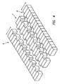
- a media transport system as schematically shown in Fig 1 having at least 2 tables forming a moving floor, preferably vacuum tables, for adhering the media to them wherein during printing the working area is fully supported by a static table.
- Fig 1 normally also comprises
- printing apparatus may comprise a sheet feeder and alignment unit in front of the printing unit having the step-wise media transport system, and a sheet lay off and stacker unit to receive the printed sheets.
- This embodiment may be used for flexible sheets as well as rigid materials. These elements are however not show for clarity.
- the media transport system The media transport system.
- a static table 1 that holds the media during a printing action when the inkjet-printing head 2 performs a fast scan along a guidance 3 over the receiving media as a swath is printed.
- the whole working part 4 of the receiving medium is substantially supported by the static table 1.
- the static table 1 has at least the width and the length to support the area of the receiving material on which the recording tool will operate, in this case an inkjet printhead 2 will record a swath of the image.
- two dynamic tables 5 and 6 are present for holding and transporting the media during a transport step, but it would be possible to use only one table if the material has a certain stiffness or can be maintained in a fixed position while the one dynamic table repositions underneath the material.
- the transport steps are performed in between printing steps, by using a step and repeat mechanism described in more detail further on.
- the receiving medium is therefore always static during printing and a high accuracy in feeding the receiving medium in distance and orientation can be obtained leading to less artefacts in the printed image.
- the forces for holding the receiving medium can be any sort of force but is preferable capable of being switched.
- the forces could be electrostatic, magnetic (certain media) or preferably vacuum.
- a static vacuum table 1 that holds the receiving medium static during the printing action.
- the top surface is formed by a rigidly fixed plate having small perforations 7 of about 0.5 to 2mm wide to enable the vacuum to attract the receiving medium lying above it during the printing action. Also small grooves (about 0.5mm)are provided to distribute the vacuum over a larger area.
- the perforations can also be replaced by small slits in the top plate.
- the plate is page-wide provided at the working area 4 which is the actual area printed by the inkjet printhead 2 during a fast scan print action.
- the aim is to thoroughly support the receiving material over the total width of the working area 4. Especially when using thin media this is important. No moving parts of the medium transport system are located under the working area 4. Only fixed parts are present under the working area 4.
- a vacuum chamber 8 in connection with the perforations 7.
- Table 1 and vacuum chamber 8 form a closed box in which a vacuum can be created. Vacuum is applied and maintained by an air evacuation system, e.g. a ventilator system, drawing air out of the vacuum chamber 8 to obtain a vacuum in the chamber.
- an air evacuation system e.g. a ventilator system
- the air evacuation system has enough capacity to generate sufficient vacuum in a short time to that the receiving medium can be immobilised on the vacuum table 1 quickly.
- the width of the receiving medium is less than the with of the plate, the problem rises that, through the perforations 7 which are not covered by the receiving sheet, air will flow into the chamber 8 and the vacuum cannot be maintained easily or is partially lost.
- a solution to this problem is that instead of a single vacuum chamber 8, the plate surface is divided into several fields each having their own vacuum chamber 8. Especially when the dimensions of these fields are chosen and designed in relation to common paper widths it is always possible to obtain a good vacuum to rigidly hold the receiving sheet in place. Vacuum chambers 8 outside the width of the receiving sheet may lose vacuum or may be switched of from the vacuum source, but have no influence on the holding power of those chambers 8 underneath the receiving sheet.
- vacuum should be discontinued in the chamber(s). This can be done by stopping the air evacuation means, but preferably a valve 9 is provided in one of the walls 10 of the vacuum chamber. The valve 9 is opened and air is let into the chamber 8 or between chambers 8.
- the cross-section of the valve 9 is preferably large and especially a blind 11 valve can be employed as they tend to have a large opening and they can be switched very quickly between open and closed state. Vacuum can be switched without even turning the air evacuation means off.
- Dynamic vacuum tables 5 and 6 provide the moving part of the media transport system. These are designed to hold the receiving layer during incremental transport steps of the receiving medium and may release the receiving layer once held by the vacuum of the static table 1.
- a dynamic vacuum table 5,6 is provided at each side of the static vacuum table 1.
- the top surface is formed by a plate having small perforations 7 to enable the vacuum to attract the receiving medium lying above it during the transport action. Also here slits can be provided
- the plate is provided page-wide to keep the transport forces constant over the width of the receiving medium.
- Vacuum is created and maintained by an air evacuation system.
- the air evacuation system has enough capacity to generate sufficient vacuum in a short time to that the receiving medium can be drawn to the dynamic vacuum table quickly.
- the width of the receiving medium is less than the width of the plate, the problem rises that through the perforations 7 which are not covered by the receiving sheet air will flow into the chamber 8 and the vacuum cannot be maintained easily or is partially lost.
- a solution to this problem given in the present invention is that instead of a single vacuum chamber 8, the plate surface is divided into several fields each having their own vacuum chamber 8. Especially when the dimensions of these fields are chosen and designed in relation to common paper widths it is always possible to obtain a good vacuum to rigidly hold the receiving sheet in place. Vacuum chambers 8 outside the width of the receiving sheet lose vacuum or are switched of from the vacuum source, but have no influence on the holding power of the other chambers 8 underneath the receiving sheet.
- blind valves 9 form an excellent method of switching the state of the vacuum table between holding and releasing state.
- dynamic vacuum tables 5,6 move, they preferably are of a lightweight construction that gives less inertia problems at the start and end of the transport step.
- both dynamic vacuum tables 5,6 move synchronously during transport of the receiving medium they are preferably relatively mounted fixed to each other.
- both dynamic vacuum tables 5,6 are driven by common spindles 12 so they always move at the same speed.
- they can be rigidly coupled to each other to form one unit which is driven by a single spindle system 12.
- a guide rail (not shown) is provided for guiding the moving tables along a correct path.
- the two dymamic tables have common guide rails to provide synchronous and parallel movement.
- Both spindles 12 may be driven by high resolution step motors 13 to have accurate control over the length of the transport step and speed.
- the guide rail and spindle system 12 over which the dynamic tables 5,6 move is rigidly fixed while the opposite rail can be mounted in a floating way to allow for the expansion of the tables 5,6.
- Using fixed rails at both sides would result in stress causing deformation of the dynamic vacuum tables 5,6 and less accurate transport of the receiving medium.
- a possible embodiment is given in fig 1 using sliding mountings 14.
- the operation of the media transport system is a step-wise incremental transport.
- a web or sheet material is provided.
- the interface between the static table 1 and the dynamic tables 5,6 can be a straight boundary, but in an alternative embodiment of the invention the tables 1,5,6 can fit to each other using a toothed pattern as shown in Fig. 4 . However it is important that the whole working area 4 of the receiving medium 15 is substantially supported by the static vacuum table 1.
- the invention can be used for the step-wise transport of a web material to be printed on, but likewise is would be possible to transport sheet material using the system.
- An improvement shown in Figure 5 that could be used in sheet feeding is that the upstream edges of one or more vacuum tables 1,5,6 is bevelled to avoid that the leading edge of a sheet hits the upstream edge of the table and a deviation would occur in feeding the sheet.
- step distance can be variable as this can be necessary in certain recording methods.
- This media holding assistance system may contain rollers (either full width rollers extending across the full width of the media or a number of smaller rollers spread along the full width of the media), fingers or styli, clamps, suction cups, etc.
- the assistance system may be mounted upstream or downstream of the working area where the printing occurs, or at both sides of the working area.
- the media holding assistance may have a set of styli 16 that can push the receiving medium 15 against the static 1 and/or dynamic table 5,6, to prevent receiving medium 15 from sliding away from these tables.
- the system may have two rows of styli 16, one row for pushing the receiving medium against the dynamic table 5,6 and the other row for pushing the receiving medium against the static table 1.
- Care must be taken that the styli 16 located above the static table 1 do not interfere with the working area 4 of the medium 15 where the printhead 2 is moved back and forth across the medium in the a fast scan direction for printing a swath of the image. If the table 1 is wide enough in the direction of receiving medium transport, the styli 16 can be placed just before and/or after the working area 4.
- the styli 16 for assisting the vacuum table 1 in holding the receiving medium 15 during printing may be placed outside, i.e. upstream or downstream the static/dynamic table assembly, i.e. on a frame part 17 of the printing apparatus where the receiving medium 15 slides over.
- This configuration is illustrated in figure 6 .
- the static 1 and dynamic 5,6 tables work in harmony with each other in a repetitive cycle of holding the receiving medium 15, e.g. the dynamic table 5,6 holding the medium 15 while moving the dynamic table 5,6 downstream, and releasing the receiving medium 15, e.g. the dynamic table 5,6 releasing the medium 15 while moving the dynamic table 5,6 upstream again.
- the styli 16 from the media holding assistance system may be activated simultaneously with the activation of the vacuum on the dynamic or static vacuum table, in which case the assisting styli 16 operate in the same repetitive cycle as the vacuum of the tables 1,5,6, but other activation schemes are perfectly possible.
- the styli 16 may be activated by pressed air and approach the receiving medium 15 from above pushing it against the supporting table 1,5,6 or frame part 17 underneath the styli 16.
- the amount and location of the sytli 16 is chosen so as to have an equal assistance of the receiving medium 15 transport over the full width of dynamic/static table or frame part in a direction perpendicular to the medium transport direction.
- the styli 16 may be roller (operation from above the receiving medium 15), suction cups (operating from underneath the receiving medium 15 and assisting to the small vacuum holes in the tables) or any other suitable means.
- the styli, rollers, suction cups, etc. may be resiliently mounted so as to not damage the receiving medium 15 on impact.
- a media holding assistance system is provided at the downstream side of the working area of printing, care must be taken the assistance means do not damage the image that was just previously printed. This may be the case in printing systems using inks that take time to dry.
- active drying means in or near the working area 4, e.g. on the shuttle together with the printhead 2, so that the printed pixels or swaths are at least "touch dry" when leaving the working area 4 and entering the area of the downstream dynamic table and/or media holding assistance system.
- the static/dynamic table assembly and vacuum support may also be assisted by roller pairs known from web transport and web tensioning systems.
- the roller pairs can hold the receiving medium in a fixed and tensioned state during printing wherein the vacuum of the static/dynamic table assembly is for holding the receiving medium flat, and forward the receiving medium in the transport direction in between the fast scans for printing a swath of the image.
- the roller pairs are preferably tension controlled and limited with a maximum torque to avoid slip of the receiving medium over the vacuum tables, i.e. to avoid that the tension of the roller pairs onto the receiving medium exceeds the holding force of the vacuum tables.
- Roller pair embodiments may include two independent rollers, one upstream and another downstream the working area of the receiving medium, operation against a sliding or rolling contact area on the printer frame or dynamic tables.
- the receiving medium moves between a roller and a part of the printer frame or dynamic table.
- the embodiment may include two roller pairs, one upstream and another downstream the working area of the receiving medium.
- the receiving medium then passes in the nip of the rollers of each of the roller pairs.
- the roller pairs may be the major means for forwarding and tensioning (if applicable) the receiving medium.
- the static/dynamic vacuum tables' functionality in the media transport is mainly to support the mesh and rigid media during transport.
- the stepping motors 13 can be directly coupled to the spindle drives 12 or they can be coupled using a gearing system. All depends upon the type of step-motor 13, spindle 12 and desired accuracy and speed of the movement.
- the two spindles need to operate exactly at the same speed, so preferably high quality motors are used which are coupled to each other by electronic gearing.
- the inkjet printhead needs to be at a constant distance from the receiving medium.
- an ink drop also follows a sloped path in its way to the receiving layer. Any distance variation will therefor result in a dislocation of the ink dot in the fast-scan direction. Distance variation can be caused by a variation in height of the printhead.
- the present transport system is capable to transport a web as shown directly from the feeding roll, although, dependent upon the type of medium to be fed, it may be advantageous to avoid tension on the receiving medium at the print location by providing a separate web feed module unrolling the feeding roll and buffering a lot of the feeding roll tension. This can provide even more accurate feeding. It has been found a significant advantage that the operation of the static/dynamic table media transport generates no shear forces in the receiving medium and that the receiving medium is in a "tensionless state" during printing.
- a solution to the problems of smudging ink or marking material on the static table 1 is provided by a static table 1 that is segmented along the length of the table, i.e. the dimension along the fast scan direction, in a number of removable sections 19.
- the removable sections may be replaced by bucket sections 20 or a single full-length bucket 21 may be provided standard underneath the full-length of the static table.
- An even more preferred embodiment of the removable static table sections 19 allows maximum support of the receiving medium 15 by not removing the whole of the static vacuum table section 19 but limiting the area that is removable from the static vacuum table section to the working area 4 of the printhead 2 or the shuttle, i.e. the area where ink or other marking material may be deposited. If the static table 1 is wider, along the direction perpendicular to the fast scan direction, than the width of a print swath, then only the area of the static table sections 19 corresponding with the area 4 of a print swath are removed or replaced with buckets 20. The remaining part of the static table sections 19 that are not corresponding with a print swath remain in place and may keep on supporting the receiving media 15 during printing of a print swath.
- the static vacuum table 1 is divided into sections along the length of the table and each section is again divided into the width direction into a working area part and a support part.
- vacuum table sections 19, working area parts and bucket sections 20 are individually mountable as inserts onto the vacuum chambers 8 underneath the static vacuum table 1. In this case, replacing table sections etc. does not involve changing the vacuum chamber configuration underneath the table.
- the distance between the marking tool, e.g. the ink jet printhead 2, and the receiving medium 15 must be very well controlled to have an optimal functioning digital printing process.
- the flatness of the media 15 itself will be of major importance.
- the flatness of the static table 1 on which the flexible media is pulled via the vacuum will be of major importance.
- the static vacuum table 1 is therefore adjustable in height at multiple locations so that it can conform to the height profile of the shuttle or printhead along the fast scan direction.
- the static table 1 may be divided into multiple sections 19 along the fast scan direction. These sections may individually be controlled at different heights. This provided optimum calibration of the distance between the marking tool 2 and the receiving medium 15, along successive sections of the fast scan movement.
- Height adjustment of the static table sections 19 may be realised by one or more height adjustment screws per section, or any other means known in the art for adjusting the height of the table sections 19. If multiple adjustment screws per table section 19 are used, not only the average height of the table section 19 but also the inclination of that table section 19 may be adjusted.
- the static table sections 19 may have a dimension, along the fast scan direction, in a range of a couple of cm up to tens of cm, depending on the targeted or required accuracy of the distance marking tool 2 to receiving medium 15.
Landscapes
- Engineering & Computer Science (AREA)
- Mechanical Engineering (AREA)
- Handling Of Sheets (AREA)
- Ink Jet (AREA)
Claims (11)
- Ein für ein Drucksystem dienendes Mediumtransportsystem zum Transportieren eines Empfangsmediums (15), wobei das Medium (15) eine Nutzfläche (4) umfasst, auf der während einer Bewegung von zumindest einem Druckkopf (2) über das Empfangsmedium (15) ein Streifen eines Bildes gedruckt wird, wobei das Mediumtransportsystem folgende Elemente umfasst :- einen feststehenden Tisch (1), der das Medium (15) trägt und so konfiguriert ist, dass er eine erste Haltekraft ausübt, durch die das Medium (15) zeitweilig festgehalten wird,- zumindest einen dynamischen Tisch (5, 6), der eine zweite Haltekraft ausübt, durch die das Empfangsmedium (15) zeitweilig festgehalten und transportiert wird,dadurch gekennzeichnet, dass der feststehende Tisch (1) so konfiguriert ist, dass er im Wesentlichen die gesamte Nutzfläche (4) des Empfangsmediums (15) trägt.
- Mediumtransportsystem nach Anspruch 1, dadurch gekennzeichnet, dass der feststehende Tisch (1) ein Vakuumtisch ist, der mit einer Vakuumkammer (8) versehen ist und die Nutzfläche (4) des Mediums (15) während des Drucks des Bildstreifens festhält, und die dynamischen Tische (5, 6) Vakuumtische sind, die mit einer Vakuumkammer (8) versehen sind und das Medium (15) während eines Transportschritts festhalten und fördern.
- Mediumtransportsystem nach Anspruch 1 oder 2, dadurch gekennzeichnet, dass der feststehende Tisch (1) zwischen zwei dynamischen Tischen (5, 6) angeordnet ist.
- Mediumtransportsystem nach einem der vorstehenden Ansprüche, dadurch gekennzeichnet, dass zumindest einer der dynamischen Tische (5, 6) und der statische Tisch (1) zahnförmig gestaltet sind.
- Mediumtransportsystem nach einem der vorstehenden Ansprüche, dadurch gekennzeichnet, dass zumindest ein Tisch (1, 5, 6) an der Mediumzuführseite einen abgeschrägten Rand aufweist.
- Mediumtransportsystem nach einem der Ansprüche 2 bis 5, dadurch gekennzeichnet, dass zumindest einer der Vakuumtische (1, 5, 6) an seiner Unterseite mit mehreren gesonderten Vakuumkammern (8) versehen ist.
- Mediumtransportsystem nach Anspruch 6, das zumindest ein Blindventil (9) in Vakuumkammer (8) aufweist, dadurch gekennzeichnet, dass das Vakuum von zumindest einer der mehreren gesonderten Vakuumkammern (8) durch Öffnen oder Schließen des zumindest einen Blindventils (9) in der Vakuumkammer (8) ein- und ausgeschaltet werden kann.
- Mediumtransportsystem nach einem der vorstehenden Ansprüche, dadurch gekennzeichnet, dass die dynamischen Tische (5, 6) so konfiguriert sind, dass sie sich gleichzeitig über Führungsschienen bewegen, und mit zumindest einem Spindelantriebsmechanismus (12, 13) versehen sind.
- Mediumtransportsystem nach Anspruch 8, dadurch gekennzeichnet, dass eine Führungsschiene fest angeordnet ist und zumindest eine weitere Führungsschiene eine hängend angeordnete Führungsschiene (14) ist.
- Mediumtransportsystem nach Anspruch 8 oder 9, dadurch gekennzeichnet, dass die Führungsschienen gemeinsam für alle dynamischen Tische (5, 6) sind.
- Tintenstrahldrucksystem, das ein Mediumtransportsystem nach einem der vorstehenden Ansprüche umfasst und dadurch gekennzeichnet ist, dass der Druckkopf (2) ein Tintenstrahldruckkopf ist.
Priority Applications (4)
| Application Number | Priority Date | Filing Date | Title |
|---|---|---|---|
| EP05104410A EP1721749B1 (de) | 2005-05-09 | 2005-05-24 | Transportvorrichtung für ein Aufzeichnungsmedium eines digitalen Druckers |
| US11/919,023 US7744210B2 (en) | 2005-05-09 | 2006-05-05 | Moving floor media transport for digital printers |
| CNA2006800158894A CN101171136A (zh) | 2005-05-09 | 2006-05-05 | 用于数字打印机的移动底板介质传输 |
| PCT/EP2006/062078 WO2006120163A1 (en) | 2005-05-09 | 2006-05-05 | Moving floor media transport for digital printers |
Applications Claiming Priority (2)
| Application Number | Priority Date | Filing Date | Title |
|---|---|---|---|
| EP05103836 | 2005-05-09 | ||
| EP05104410A EP1721749B1 (de) | 2005-05-09 | 2005-05-24 | Transportvorrichtung für ein Aufzeichnungsmedium eines digitalen Druckers |
Publications (2)
| Publication Number | Publication Date |
|---|---|
| EP1721749A1 EP1721749A1 (de) | 2006-11-15 |
| EP1721749B1 true EP1721749B1 (de) | 2010-07-28 |
Family
ID=41328798
Family Applications (1)
| Application Number | Title | Priority Date | Filing Date |
|---|---|---|---|
| EP05104410A Revoked EP1721749B1 (de) | 2005-05-09 | 2005-05-24 | Transportvorrichtung für ein Aufzeichnungsmedium eines digitalen Druckers |
Country Status (4)
| Country | Link |
|---|---|
| US (1) | US7744210B2 (de) |
| EP (1) | EP1721749B1 (de) |
| CN (1) | CN101171136A (de) |
| WO (1) | WO2006120163A1 (de) |
Cited By (1)
| Publication number | Priority date | Publication date | Assignee | Title |
|---|---|---|---|---|
| EP2803493A1 (de) | 2013-05-15 | 2014-11-19 | Agfa Graphics Nv | Bandstufen-Fördersystem |
Families Citing this family (23)
| Publication number | Priority date | Publication date | Assignee | Title |
|---|---|---|---|---|
| DE602005026369D1 (de) | 2005-05-09 | 2011-03-31 | Agfa Graphics Nv | Segmentierte Fördervorrichtung für ein Aufzeichnungsmedium und Kalibrierung des Strahlabstandes in einem digitalen Drucker |
| EP2106916B1 (de) | 2008-03-31 | 2011-05-04 | Dainippon Screen Mfg., Co., Ltd. | Bildaufzeichnungsvorrichtung |
| JP5037431B2 (ja) * | 2008-05-28 | 2012-09-26 | 大日本スクリーン製造株式会社 | 画像記録装置における記録媒体搬送装置 |
| EP2496421B1 (de) * | 2009-07-31 | 2015-06-24 | Memjet Technology Limited | Drucksystem mit fixen druckköpfen und beweglichen vakuumplatten |
| FR2954214B1 (fr) * | 2009-12-22 | 2012-01-20 | Eugene Jean Schaeffer | Dispositif de reception et d'entrainement d'un support a imprimer et une machine d'impression |
| JP5547624B2 (ja) * | 2010-12-17 | 2014-07-16 | 大日本スクリーン製造株式会社 | 画像記録装置 |
| JP5832185B2 (ja) * | 2011-07-19 | 2015-12-16 | キヤノン株式会社 | インクジェット記録装置 |
| DE102012103533A1 (de) * | 2012-04-20 | 2013-10-24 | Köra-Packmat Maschinenbau GmbH | Vorrichtung zum Fördern eines Substrats und System zum Bedrucken eines Substrats |
| US9145002B2 (en) * | 2012-12-18 | 2015-09-29 | Hewlett-Packard Development Company, L.P. | Interchangeable printer platens |
| EP3027416B1 (de) * | 2013-07-28 | 2020-10-07 | HP Scitex Ltd | Medienunterstützung |
| EP3099506B1 (de) * | 2014-01-30 | 2020-02-26 | Hewlett-Packard Development Company, L.P. | System für einen drucker mit einer druckträgerkantenführung, und drucker |
| US9586416B2 (en) * | 2014-10-21 | 2017-03-07 | Hanan Yosefi | Triple mode printer |
| EP3165371B1 (de) * | 2015-11-03 | 2018-06-06 | Agfa Nv | Tintenstrahldruckvorrichtung für starre mehrschichtige substrate |
| DE102015222142B3 (de) * | 2015-11-10 | 2016-12-08 | Lindauer Dornier Gesellschaft Mit Beschränkter Haftung | Verfahren und Vorrichtung zur Produktion und zum Abzug eines bahnförmigen Produktes |
| CN108602363B (zh) | 2015-12-09 | 2020-04-24 | 惠普发展公司,有限责任合伙企业 | 介质输出系统 |
| CN106241460B (zh) * | 2016-09-27 | 2017-12-15 | 徐州大晶新材料科技集团有限公司 | 一种薄膜输送用除静电检测装置 |
| EP3315309B1 (de) * | 2016-10-31 | 2021-08-04 | HP Scitex Ltd | Vakuum in einem palettenförderer für ein drucksystem |
| DE102017217660A1 (de) * | 2016-11-02 | 2018-05-03 | Heidelberger Druckmaschinen Ag | Bogentransportelement mit integriertem Absperrschiebersystem für Saugöffnungen |
| DE102017218930A1 (de) * | 2016-11-25 | 2018-05-30 | Heidelberger Druckmaschinen Ag | Bogentransportelement einer Druckmaschine |
| DE102017213255B3 (de) | 2017-08-01 | 2018-07-26 | Lindauer Dornier Gesellschaft Mit Beschränkter Haftung | Vorrichtung zum Abzug eines bahnförmigen Produktes von einer Webmaschine |
| DE102019103156A1 (de) | 2019-02-08 | 2020-08-13 | Bundesdruckerei Gmbh | Vorrichtung und Verfahren zum Bedrucken eines Drucksubstrats |
| US12005700B2 (en) * | 2021-03-31 | 2024-06-11 | Xerox Corporation | Airflow control via self-closing holes in movable support surface of a printing system, and related devices, systems, and methods |
| US11718107B2 (en) * | 2021-03-31 | 2023-08-08 | Xerox Corporation | Airflow control in a printing system via media registration, and related devices, systems, and methods |
Family Cites Families (7)
| Publication number | Priority date | Publication date | Assignee | Title |
|---|---|---|---|---|
| FR2562519A1 (fr) * | 1984-04-10 | 1985-10-11 | Hugon Louis | Dispositif pour assurer une continuite d'un chemin de roulement entre une table fixe et une table tournante |
| WO1996028303A1 (fr) * | 1995-03-16 | 1996-09-19 | Rohm Co., Ltd. | Machine a imprimer des cartes et son procede d'utilisation |
| AU2001228787A1 (en) * | 2000-02-01 | 2001-08-14 | Aprion Digital Ltd. | A conveyance apparatus |
| JP4055570B2 (ja) * | 2002-12-19 | 2008-03-05 | セイコーエプソン株式会社 | 液滴吐出装置 |
| EP1721751A1 (de) | 2005-05-09 | 2006-11-15 | Agfa-Gevaert | Rekonfigurierbarer Drucktisch eines digitalen Druckers |
| DE602005026369D1 (de) | 2005-05-09 | 2011-03-31 | Agfa Graphics Nv | Segmentierte Fördervorrichtung für ein Aufzeichnungsmedium und Kalibrierung des Strahlabstandes in einem digitalen Drucker |
| EP1721750A1 (de) | 2005-05-09 | 2006-11-15 | Agfa-Gevaert | Hilfsvorrichtung zur Halterung eines Mediums in einem schrittweisen Transportsystem eines digitalen Druckers |
-
2005
- 2005-05-24 EP EP05104410A patent/EP1721749B1/de not_active Revoked
-
2006
- 2006-05-05 WO PCT/EP2006/062078 patent/WO2006120163A1/en active Application Filing
- 2006-05-05 US US11/919,023 patent/US7744210B2/en not_active Expired - Fee Related
- 2006-05-05 CN CNA2006800158894A patent/CN101171136A/zh active Pending
Cited By (2)
| Publication number | Priority date | Publication date | Assignee | Title |
|---|---|---|---|---|
| EP2803493A1 (de) | 2013-05-15 | 2014-11-19 | Agfa Graphics Nv | Bandstufen-Fördersystem |
| WO2014184226A1 (en) | 2013-05-15 | 2014-11-20 | Agfa Graphics Nv | Belt step conveyor system |
Also Published As
| Publication number | Publication date |
|---|---|
| WO2006120163A1 (en) | 2006-11-16 |
| US20090284575A1 (en) | 2009-11-19 |
| EP1721749A1 (de) | 2006-11-15 |
| US7744210B2 (en) | 2010-06-29 |
| CN101171136A (zh) | 2008-04-30 |
Similar Documents
| Publication | Publication Date | Title |
|---|---|---|
| EP1721749B1 (de) | Transportvorrichtung für ein Aufzeichnungsmedium eines digitalen Druckers | |
| EP1721750A1 (de) | Hilfsvorrichtung zur Halterung eines Mediums in einem schrittweisen Transportsystem eines digitalen Druckers | |
| EP1881903B1 (de) | Digitaldruckpresse mit automatisiertem medientransport | |
| EP1534528B1 (de) | Digitaldrucker mit mehreren druckköpfen | |
| EP1776235B1 (de) | Druckverfahren und -vorrichtung | |
| US20070165092A1 (en) | Ink jet recording apparatus | |
| US20040066445A1 (en) | Vacuum holddown | |
| EP2414163B1 (de) | Ablagerung von tropfen auf einem von einem träger getragenen substrat | |
| EP1721751A1 (de) | Rekonfigurierbarer Drucktisch eines digitalen Druckers | |
| JP2011230315A (ja) | 描画装置 | |
| US20100026748A1 (en) | Printhead and method of printing | |
| JP5108790B2 (ja) | 複数の印刷カートリッジを用いた印刷装置 | |
| JP2004188655A (ja) | インクジェットプリンタ | |
| JP6739916B2 (ja) | プリント装置 | |
| JP4222605B2 (ja) | 画像形成装置 | |
| JP4480070B2 (ja) | 画像形成装置 | |
| JP2005177989A (ja) | インクジェット記録装置及びそのインクジェット記録方法 | |
| JP2000318217A (ja) | シリアル記録装置 | |
| JP2007152737A (ja) | インクジェット記録装置 | |
| JP2001191596A (ja) | インクジェットプリンタ | |
| US8669732B2 (en) | Encoder for a printer and method | |
| JP5917168B2 (ja) | 記録装置 | |
| JP2002096522A (ja) | シリアル記録装置 | |
| JP2002356045A (ja) | 画像形成装置及び画像形成方法並びに記録媒体 | |
| JP2004114351A (ja) | インクジェット式プリンタ |
Legal Events
| Date | Code | Title | Description |
|---|---|---|---|
| PUAI | Public reference made under article 153(3) epc to a published international application that has entered the european phase |
Free format text: ORIGINAL CODE: 0009012 |
|
| AK | Designated contracting states |
Kind code of ref document: A1 Designated state(s): AT BE BG CH CY CZ DE DK EE ES FI FR GB GR HU IE IS IT LI LT LU MC NL PL PT RO SE SI SK TR |
|
| AX | Request for extension of the european patent |
Extension state: AL BA HR LV MK YU |
|
| RAP1 | Party data changed (applicant data changed or rights of an application transferred) |
Owner name: AGFA GRAPHICS N.V. |
|
| 17P | Request for examination filed |
Effective date: 20070515 |
|
| AKX | Designation fees paid |
Designated state(s): DE FR GB |
|
| 17Q | First examination report despatched |
Effective date: 20071106 |
|
| GRAP | Despatch of communication of intention to grant a patent |
Free format text: ORIGINAL CODE: EPIDOSNIGR1 |
|
| GRAS | Grant fee paid |
Free format text: ORIGINAL CODE: EPIDOSNIGR3 |
|
| GRAA | (expected) grant |
Free format text: ORIGINAL CODE: 0009210 |
|
| AK | Designated contracting states |
Kind code of ref document: B1 Designated state(s): DE FR GB |
|
| REG | Reference to a national code |
Ref country code: GB Ref legal event code: FG4D |
|
| REF | Corresponds to: |
Ref document number: 602005022564 Country of ref document: DE Date of ref document: 20100909 Kind code of ref document: P |
|
| PLBI | Opposition filed |
Free format text: ORIGINAL CODE: 0009260 |
|
| PLAX | Notice of opposition and request to file observation + time limit sent |
Free format text: ORIGINAL CODE: EPIDOSNOBS2 |
|
| 26 | Opposition filed |
Opponent name: OCE-TECHNOLOGIES B.V. Effective date: 20110428 |
|
| REG | Reference to a national code |
Ref country code: DE Ref legal event code: R026 Ref document number: 602005022564 Country of ref document: DE Effective date: 20110428 |
|
| GBPC | Gb: european patent ceased through non-payment of renewal fee |
Effective date: 20110524 |
|
| REG | Reference to a national code |
Ref country code: FR Ref legal event code: ST Effective date: 20120131 |
|
| REG | Reference to a national code |
Ref country code: DE Ref legal event code: R119 Ref document number: 602005022564 Country of ref document: DE Effective date: 20111201 |
|
| PG25 | Lapsed in a contracting state [announced via postgrant information from national office to epo] |
Ref country code: FR Free format text: LAPSE BECAUSE OF NON-PAYMENT OF DUE FEES Effective date: 20110531 |
|
| PG25 | Lapsed in a contracting state [announced via postgrant information from national office to epo] |
Ref country code: GB Free format text: LAPSE BECAUSE OF NON-PAYMENT OF DUE FEES Effective date: 20110524 |
|
| RDAF | Communication despatched that patent is revoked |
Free format text: ORIGINAL CODE: EPIDOSNREV1 |
|
| PG25 | Lapsed in a contracting state [announced via postgrant information from national office to epo] |
Ref country code: DE Free format text: LAPSE BECAUSE OF NON-PAYMENT OF DUE FEES Effective date: 20111201 |
|
| RDAG | Patent revoked |
Free format text: ORIGINAL CODE: 0009271 |
|
| STAA | Information on the status of an ep patent application or granted ep patent |
Free format text: STATUS: PATENT REVOKED |
|
| 27W | Patent revoked |
Effective date: 20130504 |