EP2107190B1 - Schloss mit einer freigebbaren Dreheinheit - Google Patents
Schloss mit einer freigebbaren Dreheinheit Download PDFInfo
- Publication number
- EP2107190B1 EP2107190B1 EP20090155713 EP09155713A EP2107190B1 EP 2107190 B1 EP2107190 B1 EP 2107190B1 EP 20090155713 EP20090155713 EP 20090155713 EP 09155713 A EP09155713 A EP 09155713A EP 2107190 B1 EP2107190 B1 EP 2107190B1
- Authority
- EP
- European Patent Office
- Prior art keywords
- lock
- selector
- stop
- rotary unit
- stop element
- Prior art date
- Legal status (The legal status is an assumption and is not a legal conclusion. Google has not performed a legal analysis and makes no representation as to the accuracy of the status listed.)
- Active
Links
Images


Classifications
-
- E—FIXED CONSTRUCTIONS
- E05—LOCKS; KEYS; WINDOW OR DOOR FITTINGS; SAFES
- E05B—LOCKS; ACCESSORIES THEREFOR; HANDCUFFS
- E05B13/00—Devices preventing the key or the handle or both from being used
- E05B13/002—Devices preventing the key or the handle or both from being used locking the handle
- E05B13/004—Devices preventing the key or the handle or both from being used locking the handle by locking the spindle, follower, or the like
-
- E—FIXED CONSTRUCTIONS
- E05—LOCKS; KEYS; WINDOW OR DOOR FITTINGS; SAFES
- E05B—LOCKS; ACCESSORIES THEREFOR; HANDCUFFS
- E05B47/00—Operating or controlling locks or other fastening devices by electric or magnetic means
- E05B47/06—Controlling mechanically-operated bolts by electro-magnetically-operated detents
- E05B47/0657—Controlling mechanically-operated bolts by electro-magnetically-operated detents by locking the handle, spindle, follower or the like
- E05B47/0665—Controlling mechanically-operated bolts by electro-magnetically-operated detents by locking the handle, spindle, follower or the like radially
- E05B47/0673—Controlling mechanically-operated bolts by electro-magnetically-operated detents by locking the handle, spindle, follower or the like radially with a rectilinearly moveable blocking element
-
- E—FIXED CONSTRUCTIONS
- E05—LOCKS; KEYS; WINDOW OR DOOR FITTINGS; SAFES
- E05B—LOCKS; ACCESSORIES THEREFOR; HANDCUFFS
- E05B63/00—Locks or fastenings with special structural characteristics
- E05B63/0013—Locks with rotary bolt without provision for latching
-
- E—FIXED CONSTRUCTIONS
- E05—LOCKS; KEYS; WINDOW OR DOOR FITTINGS; SAFES
- E05B—LOCKS; ACCESSORIES THEREFOR; HANDCUFFS
- E05B63/00—Locks or fastenings with special structural characteristics
- E05B63/0065—Operating modes; Transformable to different operating modes
-
- E—FIXED CONSTRUCTIONS
- E05—LOCKS; KEYS; WINDOW OR DOOR FITTINGS; SAFES
- E05B—LOCKS; ACCESSORIES THEREFOR; HANDCUFFS
- E05B15/00—Other details of locks; Parts for engagement by bolts of fastening devices
- E05B15/0053—Other details of locks; Parts for engagement by bolts of fastening devices means providing a stable, i.e. indexed, position of lock parts
- E05B15/006—Spring-biased ball or roller entering a notch
-
- E—FIXED CONSTRUCTIONS
- E05—LOCKS; KEYS; WINDOW OR DOOR FITTINGS; SAFES
- E05B—LOCKS; ACCESSORIES THEREFOR; HANDCUFFS
- E05B63/00—Locks or fastenings with special structural characteristics
- E05B63/0065—Operating modes; Transformable to different operating modes
- E05B2063/0082—Locking modes
Definitions
- the present invention is directed to a lock for a door, a window or the like, with a lock housing, in which a locking mechanism with a locking element and a rotary unit, for example, for receiving a thumb turn unit, is received, wherein the rotary unit with the locking element for moving the Bar element cooperates between a protruding and a retracted position.
- the locking mechanism further comprises a selector member and a stop member for engaging the rotary unit to block the rotational movement of the rotary unit, the stop member being movable by the selector member.
- Locks for doors, windows or the like can be made with a turntable which can form a third unit next to the turntable for a door handle and a turntable for interaction with a lock cylinder.
- These so-called thumb turn units are usually mounted on the inside of the door with respect to a room or a building, and have the same function as a key in a lock cylinder.
- the rotary unit connected to the latch member can be rotated.
- the latch member can be displaced between a protruding position in which the latch member closes the door and a retracted position in which the latch member releases the door and the door can be opened.
- a disadvantage of a turntable for a thumb turn unit is the ability to lock the lock without a key in a locked and an unlocked state and a person who has gained unauthorized access to the room, the door by means of unlock the thumb turn unit and pass the door in the normal way.
- locks are known with a closing mechanism comprising a selector element and a stop member, wherein the stop member can engage in the rotary unit to block a rotational movement of the rotary unit.
- the stop member engages the turntable, the thumb turn unit is disabled.
- the stop element can be moved between the blocking and the release position by means of the selector element.
- the thumb turn unit is disabled.
- a lock known which is mounted in a lock housing and the Schlleßmechanlk comprises a locking element in conjunction with a rotary unit. Furthermore, the lock has a two-part lock cylinder, in which the drive unit is rotatably mounted in the lock case.
- the invention includes the technical teaching that the stop element can be transferred from an engagement position into the position for releasing the rotary unit without displacement of the selector element, wherein the transfer of the stop element into the release position by an interaction between the locking element and the stop element is executable while the Selector element is decoupled from the stop element.
- the invention discloses a lock implemented with a thumb turn unit which can be locked and released by a stop member without displacing a selector member. Consequently, it is not possible to manipulate the lock by switching the selector element back to the release position for releasing the stopper, and an unlawful person is unable to change the stalling situation of the thumbwheel unit, especially when the door is opened.
- the safety standard of the lock is improved with respect to the function of the rotary unit, for example for receiving a thumb turn unit.
- the interaction between the selector element and the stop element comprises a tapered surface, against which the selector element can only be pressed to transfer the stop element into the engaged position in the rotary unit.
- the stop element has a bolt end facing in the direction of the rotary unit.
- the rotary unit has a groove into which the bolt end of the stop element can engage in the engaged position. The stop element is displaceable along a stopper axis, and the selector element is displaceable along a selector axis, wherein the stopper axis and the selector axis are aligned perpendicular to each other.
- the installation situation of the lock has a vertical extent, wherein the stop element is displaceable in a horizontal stopper axis, wherein the selector element is displaceable in a vertical Selektorachse.
- the tapered surface of the stop member has a helix angle between the stopper axis and the selector axis of about 45 °.
- Another embodiment of the present invention relates to a spring bias of the selector element into the release position formed by the lower position with respect to the vertical extent of the lock. Consequently, a spring element is disposed within the lock housing to bias the selector element due to the bias by a spring force.
- a spring element is disposed within the lock housing to bias the selector element due to the bias by a spring force.
- the stop element remains in the engaged position. This means that the displacement of the Selektorides in the start position, which is represented by the release position in the lower position in the lock housing, and the position of the stop element with respect to the position of the selector element is decoupled, and the stop element is by a transfer of the Selektorides in his starting position can not be transferred again to the release position.
- the lock housing comprises a forend, wherein the selector element has a handle which extends for a manual displacement of the selector element through the forend.
- the displacement of the handle is possible in the lateral direction, according to a further embodiment, the handle like a push button must be pressed into the forend before the handle can be moved in the lateral direction.
- the displacement of the handle corresponds to the displacement of the selector element and thus corresponds to a vertical displacement within the Stulpes.
- the forend has a recess for receiving the Selektorides, and the handle does not protrude from the front of the Stulpes out.
- the stop element on a lever element which is rotatably received in the stop element.
- the lever element is arranged on the opposite side of the bolt end of the stop element with respect to the stopper axis. Consequently, the lever element is designed as a catch, which has a direction of rotation and a stop direction.
- the direction of rotation is made possible in the direction of the rotary unit and consequently in the direction of the engagement position of the stop element.
- the stop direction is set toward the release position of the stopper, and the stopper can be transferred to the release position by applying force to the lever member.
- the lever member is spring loaded by a spring member to hold the lever member in a vertical position which forms the stop direction.
- the locking element has an activation cam for interacting with the lever element, such that when the locking element retracts into the lock housing, the stop element retracts from the engagement position to the release position by abutment of the activation cam against the lever element Bar element is pivoted about a pivot axis.
- the locking element is rotatably received within the lock housing by a pivot axis, wherein the activation cam on the opposite side of the locking element with the engagement structure for engaging in a door frame, which consists of Lock housing protrudes, having the shape of a nose.
- the activation cam abuts against the lever member, however, the stop member does not change its position because the lever member pivots in the pivoting direction. Only when the latch member is retracted from the protruding position to the retreat position in the latch housing does abutment of the activating cam against the lever member result in retraction of the stop member to the release position because the lever member is not pivoted to the stop position.
- the stopper member can be retracted only to the release position by a key to retract the locking member into the lock housing.
- the spring member for biasing the lever member holds the lever member in a vertical position with a stopper disposed on the stopper member, and wherein the spring member urges the lever member against the stopper to hold it in an upright position.
- a roller element is arranged on the selector element, wherein the roller element forms the interacting part of the selector element with the stop element.
- the roller member rolls on the tapered surface while the selector member presses against the tapered surface to lock the bolt end of the stop member into the notch of the rotary unit.
- the roller element has the form of a small roller body which is supported by a roller axle on the selector element. The roller element avoids friction between the selector element and the stop element and improves the movement of the interaction of the selector element along the tapered surface.
- the selector element and the handle can be designed as individual parts, wherein the handle is mounted on the upper side or on the lower side of the selector element.
- the latch may have a latch, wherein the handle may be located on the upper side or on the lower side of the latch extending out of the cuff.
- the stop element is subjected to a force by a spring element, wherein the application of force is formed both in the direction of the engagement position and in the direction of the release position.
- the application of force to the stop element is formed by an interaction of a spring element with the beveled surface, wherein the spring element may be formed as a leg spring.
- the spring member biases the stop member by applying force to the tapered surface.
- the spring member urges a surface disposed on the opposite side of the tapered surface having a slope opposite to the taper of the tapered surface against which the roller member is displaced by displacement of the selector member is depressible.
- an electrical activator is provided to effect the displacement of the selector element by activation of the electrical activator.
- the electrical activator can be designed as a magnetic switch, and the activation can be carried out by a power supply of the magnetic coil. Consequently, the activation of the selector element can be carried out by pressing a push button, which can be arranged for example in the forend.
- the electric activator can open immovable manner be arranged within the lock housing, wherein the armature is connected to the selector element.
- an electrical means is disposed within the lock housing to detect the engagement or release position of the stop member and / or the position of the selector member.
- the electrical means may be designed as a tactile switch or as a contactless switch such as a magnetic switch, an inductive or a Hall sensor switch.
- the electrical means may be connected to a central control unit of the building in which the door with the lock is arranged.
- the electrical means may provide information about the engagement position or the release position of the stop element or about the activation of the selector element, for example within a hotel building or a public building.
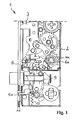
- FIG. 1 an embodiment of a lock 1 for a door, a window or the like is shown with a lock housing 2, in which a locking mechanism is incorporated according to the present invention.
- the locking mechanism comprises a locking element 3 and a rotary unit 4, which is designed to receive a thumb turning unit.
- the rotary unit 4 cooperates with the locking element 3 by means of a mechanical connection, and the locking element 3 is displaceable between a protruding and a retracted position, the locking element being shown in the retracted position.
- the lock 1 further comprises a selector element 5 and a stop member 6 for engaging the rotary unit 4 to block the rotational movement of the rotary unit 4 and to deactivate the function of the thumb turn unit.
- the stopper 6 is shown in a release position, and a bolt end 6a of the stopper 6 is not engaged in a groove 4a of the turntable 4.
- the stopper member 6 is slidable along a horizontal axis, the selector member 5 being movable along a vertical axis.
- the displacement of the stop element 6 can be generated by a displacement of the selector element 5 in the vertical direction, wherein the Connection between the selector element 5 and the stop element 6 via a tapered surface 7 is executable, which is introduced in the contour of the stop element 6.
- a roller member 11 is received on the selector member 5, the roller member forming the interacting part of the selector member 5 with the stop member 6 by rolling along the tapered surface 7 while the selector member 5 presses against the tapered surface 7 to engage the bolt end 6a of the stopper member 6 in the notch 4a of the rotary unit 4 to effect.
- the axis of movement of the stop element 6 is shown by a double arrow, wherein the axis of movement of the selector element 5 is shown by a vertical arrow.
- the selector element 5 In order to transfer the selector element 5 by a movement of the selector element 5 against the stop element 6 in the activation position, the selector element 5 has a handle 5a, which protrudes from the face plate 8, which forms the front of the lock housing 2.
- the handle 5a is designed for manual movement and together with the selector element 5 forms an individual part. If a person wishes to deactivate the function of the turntable 4, it must push the handle 5 sideways within the recess in the forend 8, and the selector element 5 pushes the stopper 6 into the engaged position by a shift to the right. When the person lets go of the handle 5a, the selector element 5 moves back to the starting position by applying a force by means of a spring element 13, through which the selector element 5 is urged toward the lower position, which forms the start position or the release position.
- FIG. 2 shows an embodiment of the lock 1 according to the present invention, wherein the locking element 3 is retracted into the lock housing 2 to open the door.
- the stopper 6 is shifted to the engaged position, and the Bolt end 6a of the stop element 6 engages in the rotary unit 4.
- the displacement of the stopper 6 in the engaged position is caused by the selector element 5, which is shifted to the upper position.
- the roller element 11 presses the stop element 6 into the engagement position in which it rolls along the tapered surface 7.
- FIG. 3 shows the lock 1 with a locking element 3, which is retracted into the lock housing 2, wherein the stop element 6, the function of the rotary unit 4 by engaging the bolt end 6a of the stop element 6 in the rotary unit 4 is deactivated.
- the selector element 5 is shifted to the lower position which constitutes the release or start position. Regardless of the position of the stopper 6, the selector element 5 is movable between each position, but the stopper 6 remains in the engaged position.
- FIG. 4 shows a lock according to the embodiment described above, wherein the locking element 3 in the protruding position for closing the lock 1, for example, for closing a door pivoted.
- the locking element 3 has an activation cam 3a, wherein the locking element 3 is pivotable about a pivot axis 14.
- the stopper member 6 is disposed in the engaged position, and the bolt end 6a of the stopper member 6 is engaged with the notch 4a of the rotary unit 4.
- the activating cam 3a pivots of the locking element 3 about the pivot axis 14, as described below.
- the stopper 6 has a lever member 9 which is rotatably received by the stopper 6.
- the lever member 9 is arranged on the opposite end of the bolt end 6a of the stop member 6, wherein the lever member 9 is designed as a detent having a pivoting direction and a stop direction. Further, the lever member 9 is spring-loaded by a spring member 10 to hold the lever member 9 in the upright position constituting the stop position.
- the stop member 6 withdraws from the engagement position to the release position by the activation cam 3a abuts against the lever member 9 due to the pivotal movement of the locking element 3.
- the activation cam 3a abuts against the lever member 9, which is arranged in the stop position, since the spring element 10, the lever member 9 against a stopper 15 force applied.
- the stopper 15 has the function of a stop, and the lever member 9 is not pivotable about the position shown counterclockwise. As a result, the stopper 6 can be displaced only by pivoting the locking element in the retracted position to the release position.
- a pivoting of the locking element 3 is possible by a key, which means that the activation of the rotary unit 4 with the associated thumb rotation unit can be performed only via a key regardless of the position of the selector element 5.
- the present invention is not limited to the embodiment described above, which is given by way of example only, this may be varied in various ways within the scope defined by the claims. consequently the invention is also applicable to various embodiments, in particular the design of the lock 1, which may have a trap or which is carried out without a door trap, and which is designed only for closing a door.
Landscapes
- Engineering & Computer Science (AREA)
- Structural Engineering (AREA)
- Lock And Its Accessories (AREA)
Applications Claiming Priority (1)
| Application Number | Priority Date | Filing Date | Title |
|---|---|---|---|
| DE200810016699 DE102008016699B4 (de) | 2008-03-31 | 2008-03-31 | Schloss mit einer freigebbaren Dreheinheit |
Publications (3)
| Publication Number | Publication Date |
|---|---|
| EP2107190A2 EP2107190A2 (de) | 2009-10-07 |
| EP2107190A3 EP2107190A3 (de) | 2011-02-23 |
| EP2107190B1 true EP2107190B1 (de) | 2013-02-20 |
Family
ID=40937401
Family Applications (1)
| Application Number | Title | Priority Date | Filing Date |
|---|---|---|---|
| EP20090155713 Active EP2107190B1 (de) | 2008-03-31 | 2009-03-20 | Schloss mit einer freigebbaren Dreheinheit |
Country Status (4)
| Country | Link |
|---|---|
| EP (1) | EP2107190B1 (da) |
| CN (1) | CN101550784B (da) |
| DE (1) | DE102008016699B4 (da) |
| DK (1) | DK2107190T3 (da) |
Families Citing this family (8)
| Publication number | Priority date | Publication date | Assignee | Title |
|---|---|---|---|---|
| DE102009006495A1 (de) | 2009-01-28 | 2010-08-05 | Dorma Gmbh + Co. Kg | Schloss, insbesondere Schwenkriegelschloss, mit erhöhter Schutzwirkung |
| SE1050383A1 (sv) * | 2010-04-19 | 2011-02-15 | Assa Oem Ab | Lås med blockeringsfunktion för en regel |
| SE1050617A1 (sv) * | 2010-06-16 | 2011-06-21 | Assa Oem Ab | Låsanordning med omställbar spärranordning |
| DE102011000884A1 (de) | 2011-02-23 | 2012-08-23 | Dorma Gmbh + Co. Kg | Schwenkriegelschloss für eine Tür, ein Fenster, ein Deckelelement oder dergleichen |
| EP2518241B1 (de) * | 2011-04-26 | 2014-03-19 | Roto Frank Ag | Türschloss |
| CN102733673A (zh) * | 2012-07-03 | 2012-10-17 | 上海欧一安保器材有限公司 | 利用杠杆传动分力的预压阴极锁 |
| DE102012111537A1 (de) | 2012-11-28 | 2014-05-28 | Dorma Gmbh + Co. Kg | Schloss mit einer freigebbaren Dreheinheit |
| SE543487C2 (en) * | 2019-05-17 | 2021-03-02 | Stendals El Ab | Catch mechanism with a first and a second connector for a bolt and a locking device |
Family Cites Families (5)
| Publication number | Priority date | Publication date | Assignee | Title |
|---|---|---|---|---|
| FR2620482B1 (fr) * | 1987-09-15 | 1990-01-19 | D S Croisee | Loquet pour panneau coulissant |
| NZ299577A (en) * | 1996-10-14 | 1998-01-26 | Nt Legge Pacific Ltd | Mortice lock, actuating handles selectable to allow bolt movement even when locked, and where the lock can be handed |
| SE521128C2 (sv) * | 2002-03-15 | 2003-09-30 | Assa Ab | Låsanordning med vredspärr |
| FR2875526B1 (fr) * | 2004-09-17 | 2008-04-18 | Vachette Sa | Serrure de porte a pene demi-tour |
| EP1683936B1 (de) * | 2004-12-18 | 2007-07-04 | Roto Frank Ag | Schloss mit Falle und Fallenantrieb |
-
2008
- 2008-03-31 DE DE200810016699 patent/DE102008016699B4/de not_active Expired - Fee Related
-
2009
- 2009-03-20 EP EP20090155713 patent/EP2107190B1/de active Active
- 2009-03-20 DK DK09155713T patent/DK2107190T3/da active
- 2009-03-30 CN CN2009101314202A patent/CN101550784B/zh active Active
Also Published As
| Publication number | Publication date |
|---|---|
| CN101550784A (zh) | 2009-10-07 |
| DE102008016699B4 (de) | 2012-04-12 |
| CN101550784B (zh) | 2012-08-29 |
| DE102008016699A1 (de) | 2009-10-08 |
| DK2107190T3 (da) | 2013-05-13 |
| EP2107190A3 (de) | 2011-02-23 |
| EP2107190A2 (de) | 2009-10-07 |
Similar Documents
| Publication | Publication Date | Title |
|---|---|---|
| EP2107190B1 (de) | Schloss mit einer freigebbaren Dreheinheit | |
| EP1932989B1 (de) | Schliessanlage für Türen, Fenster oder dergleichen, insbesondere Treibstangenschloss mit Panikfunktion und Mehrpunktverriegelung | |
| DE19983294B4 (de) | Elektrisch gesteuertes Schloss | |
| DE2911681C2 (de) | Elektrische Zentralverriegelungsvorrichtung für Kraftfahrzeugtüren | |
| EP1970507B1 (de) | Panikschloss | |
| EP1970505B1 (de) | Panikschloss | |
| EP2543802B1 (de) | Schloss | |
| EP2385197B1 (de) | Schloss | |
| WO2012107167A1 (de) | Schlosssystem für eine zweiflügelige türanlage mit panikfunktion | |
| EP0410122B1 (de) | Einsteckschloss mit Fallen-Feststellung | |
| DE3631118C2 (de) | Sicherheitsschloß | |
| DE102010028647B3 (de) | Schloss | |
| EP0779404B1 (de) | SIcherheitsschloss | |
| EP2385196B1 (de) | Schloss | |
| EP2390445B1 (de) | Schloss | |
| EP1970506B1 (de) | Selbstverriegelndes panikschloss | |
| DE102006005996A1 (de) | Türschloss in Verbindung mit elektrischem Türöffner für mechanisch selbst stellende Mehrfach-Verriegelung | |
| EP2392752A2 (de) | Schloss und Tür, Fenster oder dergleichen mit einem Schloss | |
| EP2385194B1 (de) | Schloss | |
| EP0779403B1 (de) | Sicherheitsschloss | |
| EP2738324B1 (de) | Schloss mit einer freigebbaren Dreheinheit | |
| EP1156180B1 (de) | Schloss mit Vorschlussvergrösserung und Panikfunktion | |
| DE19812276C1 (de) | Sicherheitsschloß | |
| EP3569801B1 (de) | Schloss, insbesondere panikschloss | |
| EP3543437B1 (de) | Schlossanordnung mit einem schloss für eine gangflügeltür und einem gegenschloss für eine standflügeltür |
Legal Events
| Date | Code | Title | Description |
|---|---|---|---|
| PUAI | Public reference made under article 153(3) epc to a published international application that has entered the european phase |
Free format text: ORIGINAL CODE: 0009012 |
|
| AK | Designated contracting states |
Kind code of ref document: A2 Designated state(s): AT BE BG CH CY CZ DE DK EE ES FI FR GB GR HR HU IE IS IT LI LT LU LV MC MK MT NL NO PL PT RO SE SI SK TR |
|
| AX | Request for extension of the european patent |
Extension state: AL BA RS |
|
| RAP1 | Party data changed (applicant data changed or rights of an application transferred) |
Owner name: DORMA GMBH + CO. KG |
|
| PUAL | Search report despatched |
Free format text: ORIGINAL CODE: 0009013 |
|
| AK | Designated contracting states |
Kind code of ref document: A3 Designated state(s): AT BE BG CH CY CZ DE DK EE ES FI FR GB GR HR HU IE IS IT LI LT LU LV MC MK MT NL NO PL PT RO SE SI SK TR |
|
| AX | Request for extension of the european patent |
Extension state: AL BA RS |
|
| 17P | Request for examination filed |
Effective date: 20110406 |
|
| RIC1 | Information provided on ipc code assigned before grant |
Ipc: E05B 17/22 20060101AFI20110524BHEP Ipc: E05B 15/00 20060101ALN20110524BHEP Ipc: E05B 63/16 20060101ALI20110524BHEP Ipc: E05B 13/00 20060101ALI20110524BHEP |
|
| GRAP | Despatch of communication of intention to grant a patent |
Free format text: ORIGINAL CODE: EPIDOSNIGR1 |
|
| AKX | Designation fees paid |
Designated state(s): AT BE BG CH CY CZ DE DK EE ES FI FR GB GR HR HU IE IS IT LI LT LU LV MC MK MT NL NO PL PT RO SE SI SK TR |
|
| GRAS | Grant fee paid |
Free format text: ORIGINAL CODE: EPIDOSNIGR3 |
|
| 17Q | First examination report despatched |
Effective date: 20120626 |
|
| GRAA | (expected) grant |
Free format text: ORIGINAL CODE: 0009210 |
|
| AK | Designated contracting states |
Kind code of ref document: B1 Designated state(s): AT BE BG CH CY CZ DE DK EE ES FI FR GB GR HR HU IE IS IT LI LT LU LV MC MK MT NL NO PL PT RO SE SI SK TR |
|
| REG | Reference to a national code |
Ref country code: GB Ref legal event code: FG4D Free format text: NOT ENGLISH |
|
| REG | Reference to a national code |
Ref country code: CH Ref legal event code: EP |
|
| REG | Reference to a national code |
Ref country code: AT Ref legal event code: REF Ref document number: 597652 Country of ref document: AT Kind code of ref document: T Effective date: 20130315 |
|
| REG | Reference to a national code |
Ref country code: IE Ref legal event code: FG4D Free format text: LANGUAGE OF EP DOCUMENT: GERMAN |
|
| REG | Reference to a national code |
Ref country code: DE Ref legal event code: R096 Ref document number: 502009006267 Country of ref document: DE Effective date: 20130418 |
|
| REG | Reference to a national code |
Ref country code: DK Ref legal event code: T3 |
|
| REG | Reference to a national code |
Ref country code: SE Ref legal event code: TRGR |
|
| REG | Reference to a national code |
Ref country code: EE Ref legal event code: FG4A Ref document number: E007899 Country of ref document: EE Effective date: 20130411 |
|
| REG | Reference to a national code |
Ref country code: NO Ref legal event code: T2 Effective date: 20130220 |
|
| REG | Reference to a national code |
Ref country code: NL Ref legal event code: VDEP Effective date: 20130220 |
|
| PG25 | Lapsed in a contracting state [announced via postgrant information from national office to epo] |
Ref country code: IS Free format text: LAPSE BECAUSE OF FAILURE TO SUBMIT A TRANSLATION OF THE DESCRIPTION OR TO PAY THE FEE WITHIN THE PRESCRIBED TIME-LIMIT Effective date: 20130620 Ref country code: ES Free format text: LAPSE BECAUSE OF FAILURE TO SUBMIT A TRANSLATION OF THE DESCRIPTION OR TO PAY THE FEE WITHIN THE PRESCRIBED TIME-LIMIT Effective date: 20130531 Ref country code: BG Free format text: LAPSE BECAUSE OF FAILURE TO SUBMIT A TRANSLATION OF THE DESCRIPTION OR TO PAY THE FEE WITHIN THE PRESCRIBED TIME-LIMIT Effective date: 20130520 |
|
| PG25 | Lapsed in a contracting state [announced via postgrant information from national office to epo] |
Ref country code: GR Free format text: LAPSE BECAUSE OF FAILURE TO SUBMIT A TRANSLATION OF THE DESCRIPTION OR TO PAY THE FEE WITHIN THE PRESCRIBED TIME-LIMIT Effective date: 20130521 Ref country code: PL Free format text: LAPSE BECAUSE OF FAILURE TO SUBMIT A TRANSLATION OF THE DESCRIPTION OR TO PAY THE FEE WITHIN THE PRESCRIBED TIME-LIMIT Effective date: 20130220 Ref country code: PT Free format text: LAPSE BECAUSE OF FAILURE TO SUBMIT A TRANSLATION OF THE DESCRIPTION OR TO PAY THE FEE WITHIN THE PRESCRIBED TIME-LIMIT Effective date: 20130620 Ref country code: SI Free format text: LAPSE BECAUSE OF FAILURE TO SUBMIT A TRANSLATION OF THE DESCRIPTION OR TO PAY THE FEE WITHIN THE PRESCRIBED TIME-LIMIT Effective date: 20130220 |
|
| BERE | Be: lapsed |
Owner name: DORMA G.M.B.H. + CO. KG Effective date: 20130331 |
|
| PG25 | Lapsed in a contracting state [announced via postgrant information from national office to epo] |
Ref country code: HR Free format text: LAPSE BECAUSE OF FAILURE TO SUBMIT A TRANSLATION OF THE DESCRIPTION OR TO PAY THE FEE WITHIN THE PRESCRIBED TIME-LIMIT Effective date: 20130220 |
|
| PG25 | Lapsed in a contracting state [announced via postgrant information from national office to epo] |
Ref country code: SK Free format text: LAPSE BECAUSE OF FAILURE TO SUBMIT A TRANSLATION OF THE DESCRIPTION OR TO PAY THE FEE WITHIN THE PRESCRIBED TIME-LIMIT Effective date: 20130220 Ref country code: MC Free format text: LAPSE BECAUSE OF NON-PAYMENT OF DUE FEES Effective date: 20130331 Ref country code: NL Free format text: LAPSE BECAUSE OF FAILURE TO SUBMIT A TRANSLATION OF THE DESCRIPTION OR TO PAY THE FEE WITHIN THE PRESCRIBED TIME-LIMIT Effective date: 20130220 Ref country code: RO Free format text: LAPSE BECAUSE OF FAILURE TO SUBMIT A TRANSLATION OF THE DESCRIPTION OR TO PAY THE FEE WITHIN THE PRESCRIBED TIME-LIMIT Effective date: 20130220 Ref country code: CZ Free format text: LAPSE BECAUSE OF FAILURE TO SUBMIT A TRANSLATION OF THE DESCRIPTION OR TO PAY THE FEE WITHIN THE PRESCRIBED TIME-LIMIT Effective date: 20130220 |
|
| REG | Reference to a national code |
Ref country code: CH Ref legal event code: PL |
|
| PLBE | No opposition filed within time limit |
Free format text: ORIGINAL CODE: 0009261 |
|
| REG | Reference to a national code |
Ref country code: FR Ref legal event code: ST Effective date: 20131129 |
|
| STAA | Information on the status of an ep patent application or granted ep patent |
Free format text: STATUS: NO OPPOSITION FILED WITHIN TIME LIMIT |
|
| PG25 | Lapsed in a contracting state [announced via postgrant information from national office to epo] |
Ref country code: IT Free format text: LAPSE BECAUSE OF FAILURE TO SUBMIT A TRANSLATION OF THE DESCRIPTION OR TO PAY THE FEE WITHIN THE PRESCRIBED TIME-LIMIT Effective date: 20130220 |
|
| REG | Reference to a national code |
Ref country code: IE Ref legal event code: MM4A |
|
| 26N | No opposition filed |
Effective date: 20131121 |
|
| GBPC | Gb: european patent ceased through non-payment of renewal fee |
Effective date: 20130520 |
|
| PG25 | Lapsed in a contracting state [announced via postgrant information from national office to epo] |
Ref country code: CH Free format text: LAPSE BECAUSE OF NON-PAYMENT OF DUE FEES Effective date: 20130331 Ref country code: IE Free format text: LAPSE BECAUSE OF NON-PAYMENT OF DUE FEES Effective date: 20130320 Ref country code: LI Free format text: LAPSE BECAUSE OF NON-PAYMENT OF DUE FEES Effective date: 20130331 Ref country code: FR Free format text: LAPSE BECAUSE OF NON-PAYMENT OF DUE FEES Effective date: 20130422 Ref country code: BE Free format text: LAPSE BECAUSE OF NON-PAYMENT OF DUE FEES Effective date: 20130331 |
|
| REG | Reference to a national code |
Ref country code: DE Ref legal event code: R097 Ref document number: 502009006267 Country of ref document: DE Effective date: 20131121 |
|
| PG25 | Lapsed in a contracting state [announced via postgrant information from national office to epo] |
Ref country code: GB Free format text: LAPSE BECAUSE OF NON-PAYMENT OF DUE FEES Effective date: 20130520 |
|
| PGFP | Annual fee paid to national office [announced via postgrant information from national office to epo] |
Ref country code: LT Payment date: 20140221 Year of fee payment: 6 Ref country code: EE Payment date: 20140312 Year of fee payment: 6 |
|
| PGFP | Annual fee paid to national office [announced via postgrant information from national office to epo] |
Ref country code: LV Payment date: 20140312 Year of fee payment: 6 |
|
| PG25 | Lapsed in a contracting state [announced via postgrant information from national office to epo] |
Ref country code: MT Free format text: LAPSE BECAUSE OF FAILURE TO SUBMIT A TRANSLATION OF THE DESCRIPTION OR TO PAY THE FEE WITHIN THE PRESCRIBED TIME-LIMIT Effective date: 20130220 |
|
| REG | Reference to a national code |
Ref country code: DE Ref legal event code: R082 Ref document number: 502009006267 Country of ref document: DE Representative=s name: DENNEMEYER & ASSOCIATES S.A., LU Ref country code: DE Ref legal event code: R082 Ref document number: 502009006267 Country of ref document: DE |
|
| REG | Reference to a national code |
Ref country code: DE Ref legal event code: R081 Ref document number: 502009006267 Country of ref document: DE Owner name: DORMAKABA DEUTSCHLAND GMBH, DE Free format text: FORMER OWNER: DORMA GMBH & CO. KG, 58256 ENNEPETAL, DE Effective date: 20141210 Ref country code: DE Ref legal event code: R081 Ref document number: 502009006267 Country of ref document: DE Owner name: DORMA DEUTSCHLAND GMBH, DE Free format text: FORMER OWNER: DORMA GMBH & CO. KG, 58256 ENNEPETAL, DE Effective date: 20141210 Ref country code: DE Ref legal event code: R082 Ref document number: 502009006267 Country of ref document: DE Representative=s name: DENNEMEYER & ASSOCIATES S.A., LU Effective date: 20141002 Ref country code: DE Ref legal event code: R082 Ref document number: 502009006267 Country of ref document: DE Representative=s name: BALDER IP LAW, S.L., ES Effective date: 20141002 |
|
| REG | Reference to a national code |
Ref country code: NO Ref legal event code: CHAD Owner name: DORMA DEUTCHLAND GMBH, DE |
|
| REG | Reference to a national code |
Ref country code: AT Ref legal event code: MM01 Ref document number: 597652 Country of ref document: AT Kind code of ref document: T Effective date: 20140320 |
|
| REG | Reference to a national code |
Ref country code: DE Ref legal event code: R082 Ref document number: 502009006267 Country of ref document: DE Representative=s name: BALDER IP LAW, S.L., ES |
|
| PG25 | Lapsed in a contracting state [announced via postgrant information from national office to epo] |
Ref country code: CY Free format text: LAPSE BECAUSE OF FAILURE TO SUBMIT A TRANSLATION OF THE DESCRIPTION OR TO PAY THE FEE WITHIN THE PRESCRIBED TIME-LIMIT Effective date: 20130220 Ref country code: TR Free format text: LAPSE BECAUSE OF FAILURE TO SUBMIT A TRANSLATION OF THE DESCRIPTION OR TO PAY THE FEE WITHIN THE PRESCRIBED TIME-LIMIT Effective date: 20130220 |
|
| PG25 | Lapsed in a contracting state [announced via postgrant information from national office to epo] |
Ref country code: MK Free format text: LAPSE BECAUSE OF FAILURE TO SUBMIT A TRANSLATION OF THE DESCRIPTION OR TO PAY THE FEE WITHIN THE PRESCRIBED TIME-LIMIT Effective date: 20130220 Ref country code: LU Free format text: LAPSE BECAUSE OF NON-PAYMENT OF DUE FEES Effective date: 20130320 Ref country code: HU Free format text: LAPSE BECAUSE OF FAILURE TO SUBMIT A TRANSLATION OF THE DESCRIPTION OR TO PAY THE FEE WITHIN THE PRESCRIBED TIME-LIMIT; INVALID AB INITIO Effective date: 20090320 |
|
| PG25 | Lapsed in a contracting state [announced via postgrant information from national office to epo] |
Ref country code: AT Free format text: LAPSE BECAUSE OF NON-PAYMENT OF DUE FEES Effective date: 20140320 |
|
| REG | Reference to a national code |
Ref country code: LT Ref legal event code: MM4D Effective date: 20150320 |
|
| PG25 | Lapsed in a contracting state [announced via postgrant information from national office to epo] |
Ref country code: LT Free format text: LAPSE BECAUSE OF NON-PAYMENT OF DUE FEES Effective date: 20150320 |
|
| REG | Reference to a national code |
Ref country code: EE Ref legal event code: MM4A Ref document number: E007899 Country of ref document: EE Effective date: 20150331 |
|
| PG25 | Lapsed in a contracting state [announced via postgrant information from national office to epo] |
Ref country code: LV Free format text: LAPSE BECAUSE OF NON-PAYMENT OF DUE FEES Effective date: 20150320 |
|
| PG25 | Lapsed in a contracting state [announced via postgrant information from national office to epo] |
Ref country code: EE Free format text: LAPSE BECAUSE OF NON-PAYMENT OF DUE FEES Effective date: 20150331 |
|
| REG | Reference to a national code |
Ref country code: NO Ref legal event code: CHAD Owner name: DORMA DEUTSCHLAND GMBH, DE |
|
| REG | Reference to a national code |
Ref country code: NO Ref legal event code: CHAD Owner name: DORMAKABA DEUTSCHLAND GMBH, DE |
|
| REG | Reference to a national code |
Ref country code: DE Ref legal event code: R082 Ref document number: 502009006267 Country of ref document: DE Representative=s name: BALDER IP LAW, S.L., ES Ref country code: DE Ref legal event code: R081 Ref document number: 502009006267 Country of ref document: DE Owner name: DORMAKABA DEUTSCHLAND GMBH, DE Free format text: FORMER OWNER: DORMA DEUTSCHLAND GMBH, 58256 ENNEPETAL, DE |
|
| PGFP | Annual fee paid to national office [announced via postgrant information from national office to epo] |
Ref country code: NO Payment date: 20230324 Year of fee payment: 15 Ref country code: FI Payment date: 20230321 Year of fee payment: 15 Ref country code: DK Payment date: 20230323 Year of fee payment: 15 |
|
| PGFP | Annual fee paid to national office [announced via postgrant information from national office to epo] |
Ref country code: SE Payment date: 20230314 Year of fee payment: 15 Ref country code: DE Payment date: 20230321 Year of fee payment: 15 |