EP2105625B1 - Clutch control device - Google Patents
Clutch control device Download PDFInfo
- Publication number
- EP2105625B1 EP2105625B1 EP09153083.2A EP09153083A EP2105625B1 EP 2105625 B1 EP2105625 B1 EP 2105625B1 EP 09153083 A EP09153083 A EP 09153083A EP 2105625 B1 EP2105625 B1 EP 2105625B1
- Authority
- EP
- European Patent Office
- Prior art keywords
- clutch
- control
- amount
- rotating body
- engagement
- Prior art date
- Legal status (The legal status is an assumption and is not a legal conclusion. Google has not performed a legal analysis and makes no representation as to the accuracy of the status listed.)
- Ceased
Links
- 238000001514 detection method Methods 0.000 claims description 65
- 230000005540 biological transmission Effects 0.000 claims description 48
- 230000007935 neutral effect Effects 0.000 claims description 21
- 239000012530 fluid Substances 0.000 claims description 6
- 238000010586 diagram Methods 0.000 description 12
- 238000013016 damping Methods 0.000 description 9
- 230000002093 peripheral effect Effects 0.000 description 8
- 239000000314 lubricant Substances 0.000 description 6
- 230000001360 synchronised effect Effects 0.000 description 5
- 238000012986 modification Methods 0.000 description 1
- 230000004048 modification Effects 0.000 description 1
- 239000013643 reference control Substances 0.000 description 1
- 230000035939 shock Effects 0.000 description 1
Images


Classifications
-
- F—MECHANICAL ENGINEERING; LIGHTING; HEATING; WEAPONS; BLASTING
- F16—ENGINEERING ELEMENTS AND UNITS; GENERAL MEASURES FOR PRODUCING AND MAINTAINING EFFECTIVE FUNCTIONING OF MACHINES OR INSTALLATIONS; THERMAL INSULATION IN GENERAL
- F16D—COUPLINGS FOR TRANSMITTING ROTATION; CLUTCHES; BRAKES
- F16D48/00—External control of clutches
- F16D48/06—Control by electric or electronic means, e.g. of fluid pressure
- F16D48/066—Control of fluid pressure, e.g. using an accumulator
-
- F—MECHANICAL ENGINEERING; LIGHTING; HEATING; WEAPONS; BLASTING
- F16—ENGINEERING ELEMENTS AND UNITS; GENERAL MEASURES FOR PRODUCING AND MAINTAINING EFFECTIVE FUNCTIONING OF MACHINES OR INSTALLATIONS; THERMAL INSULATION IN GENERAL
- F16D—COUPLINGS FOR TRANSMITTING ROTATION; CLUTCHES; BRAKES
- F16D2500/00—External control of clutches by electric or electronic means
- F16D2500/30—Signal inputs
- F16D2500/302—Signal inputs from the actuator
- F16D2500/3024—Pressure
-
- F—MECHANICAL ENGINEERING; LIGHTING; HEATING; WEAPONS; BLASTING
- F16—ENGINEERING ELEMENTS AND UNITS; GENERAL MEASURES FOR PRODUCING AND MAINTAINING EFFECTIVE FUNCTIONING OF MACHINES OR INSTALLATIONS; THERMAL INSULATION IN GENERAL
- F16D—COUPLINGS FOR TRANSMITTING ROTATION; CLUTCHES; BRAKES
- F16D2500/00—External control of clutches by electric or electronic means
- F16D2500/30—Signal inputs
- F16D2500/304—Signal inputs from the clutch
- F16D2500/30406—Clutch slip
-
- F—MECHANICAL ENGINEERING; LIGHTING; HEATING; WEAPONS; BLASTING
- F16—ENGINEERING ELEMENTS AND UNITS; GENERAL MEASURES FOR PRODUCING AND MAINTAINING EFFECTIVE FUNCTIONING OF MACHINES OR INSTALLATIONS; THERMAL INSULATION IN GENERAL
- F16D—COUPLINGS FOR TRANSMITTING ROTATION; CLUTCHES; BRAKES
- F16D2500/00—External control of clutches by electric or electronic means
- F16D2500/30—Signal inputs
- F16D2500/306—Signal inputs from the engine
- F16D2500/3067—Speed of the engine
-
- F—MECHANICAL ENGINEERING; LIGHTING; HEATING; WEAPONS; BLASTING
- F16—ENGINEERING ELEMENTS AND UNITS; GENERAL MEASURES FOR PRODUCING AND MAINTAINING EFFECTIVE FUNCTIONING OF MACHINES OR INSTALLATIONS; THERMAL INSULATION IN GENERAL
- F16D—COUPLINGS FOR TRANSMITTING ROTATION; CLUTCHES; BRAKES
- F16D2500/00—External control of clutches by electric or electronic means
- F16D2500/30—Signal inputs
- F16D2500/308—Signal inputs from the transmission
- F16D2500/3081—Signal inputs from the transmission from the input shaft
- F16D2500/30816—Speed of the input shaft
-
- F—MECHANICAL ENGINEERING; LIGHTING; HEATING; WEAPONS; BLASTING
- F16—ENGINEERING ELEMENTS AND UNITS; GENERAL MEASURES FOR PRODUCING AND MAINTAINING EFFECTIVE FUNCTIONING OF MACHINES OR INSTALLATIONS; THERMAL INSULATION IN GENERAL
- F16D—COUPLINGS FOR TRANSMITTING ROTATION; CLUTCHES; BRAKES
- F16D2500/00—External control of clutches by electric or electronic means
- F16D2500/50—Problem to be solved by the control system
- F16D2500/502—Relating the clutch
- F16D2500/50245—Calibration or recalibration of the clutch touch-point
- F16D2500/50251—During operation
- F16D2500/50254—Brake actuated
Definitions
- the present invention relates to a transmission system including a clutch which connects and disconnects a rotational driving force transmitted to a drive wheel from a power source of a vehicle, and a clutch control device which can detect an engagement start of a clutch by measuring rotational speeds of an input side rotating body and an output side rotating body of the clutch.
- a clutch device has been known conventionally in which a clutch for transmitting a rotational driving force of a power source to a drive wheel by a frictional force of a friction plate (clutch plate) is drive-controlled by an actuator.
- a clutch device for example, when the clutch plate is worn out and becomes thin, the same frictional force may not be acquired even if a drive amount of the actuator is the same as before.
- Such a problem can be solved by, for example, detecting a movement amount required for clutch plates, which are apart from each other, to come into contact with each other, and by increasing the drive amount of the actuator in accordance with an increase of this movement amount.
- US 2007/199395 A discloses a transmission system including a clutch which connects and disconnects a rotational driving force transmitted to a drive wheel from a power source of a vehicle, the clutch including an input side rotating body and an output side rotating body which synchronously rotate with the clutch being connected, the transmission system comprising:
- An object of the present invention is to provide an improved transmission system of the above kind having a clutch control device which can detect an engagement start of a clutch by measuring rotational speeds of an input side rotating body and an output side rotating body of the clutch.
- a clutch control device for a clutch connects and disconnects a rotational driving force transmitted to a drive wheel from a power source of a vehicle.
- the clutch includes an input side rotating body and an output side rotating body which synchronously rotate with the clutch being connected.
- the clutch control device includes: input side rotational speed detection means for detecting a rotational speed of the input side rotating body; output side rotational speed detection means for detecting a rotational speed of the output side rotating body; clutch control means for controlling an control amount of the clutch; brake means for temporarily stopping the output side rotating body while the clutch is disconnected; clutch-control-amount detection means for detecting the control amount of the clutch; engagement start detection means for detecting an engagement start of the clutch when a rotational speed difference between the input side rotating body and the output side rotating body becomes equal to or less than a predetermined value; engagement-start control-amount detection means for detecting the control amount of the clutch in the engagement start; and clutch-correction-control-amount deriving means for deriving an correction control amount of the clutch on the basis of the control amount of the clutch when the engagement start is detected after the output side rotating body is stopped temporarily.
- the clutch control means feedback-controls the control amount of the clutch on the basis of the correction control amount. Furthermore, the brake means continues a brake operation for a pre
- the clutch is of a hydraulic type, and the engagement-start control-amount detection means derives the control amount of the clutch on the basis of an oil pressure generated in the clutch.
- a third aspect is that the clutch is of an hydraulic type driven by an oil pressure supplied from an oil pressure supply source; the clutch control device further comprises an actuator which is provided between the oil pressure supply source and the clutch and which controls a flow rate of a hydraulic fluid supplied to the clutch; and the engagement-start control-amount detection means derives the control amount of the clutch on the basis of a drive current value of the actuator.
- the clutch control device further includes a staged transmission which transmits the rotational driving force to the drive wheel with a predetermined gear ratio;
- the clutch is a twin clutch including a first clutch and a second clutch, and is structured so that a connecting-and-disconnecting state of the twin clutch may be switched alternatively for every shifting operation of the staged transmission;
- the staged transmission is structured so that, among an odd-numbered speed gear and an even-numbered speed gear, a gear on a side where the rotational driving force is not transmitted can be made into a neutral state by disconnecting any one of the first clutch and the second clutch; and the engagement start detection means detects the engagement start with respect to the disconnected side of any of the first clutch and the second clutch.
- a fifth aspect is that the engagement start detection means detects the engagement start at every predetermined cycle.
- a sixth aspect is that the clutch-correction-control-amount deriving means derives the correction control amount on the basis of a data table which specifies in advance a relation between the control amount of the clutch and the correction control amount at the time when the engagement start is detected.
- a seventh aspect is that the clutch control means with warning means that the control amount of the clutch at the time when the engagement start is detected exceeds a predetermined value.
- the brake means temporarily stops the output side rotating body of the clutch, and thereafter an engagement start of the clutch is detected as the rotational speed difference between the input side rotating body and the output side rotating body becomes equal to or less than a predetermined value.
- a correction control amount of the clutch is derived on the basis of the control amount of the clutch when the engagement start is detected. Then, on the basis of this correction control amount, the clutch is feedback-controlled.
- the brake means continues a brake operation for a predetermined period even after the output side rotating body is stopped temporarily.
- the output side rotating body tends to rotate, even after the main shaft is stopped temporarily, by the viscosity of a lubricant of the clutch, friction, or the like, the rotation can be prevented and an engagement start of the clutch can be detected.
- the clutch is of the hydraulic type, and the engagement-start control-amount detection means derives the control amount of the clutch on the basis of an oil pressure generated in the clutch.
- oil pressure detection means which measures the oil pressure generated in the clutch.
- the clutch is of the hydraulic type driven by an oil pressure supplied from the oil pressure supply source.
- the clutch control device includes the actuator which is provided between the oil pressure supply source and the clutch, and which controls a flow rate of the hydraulic fluid supplied to the clutch.
- the engagement-start control-amount detection means derives the control amount of the clutch on the basis of a drive current value of the actuator. Thus, it becomes possible to derive a control amount of the clutch on the basis of the drive current value of the actuator.
- the clutch control device includes the staged transmission which transmits the rotational driving force to the drive wheel with a predetermined gear ratio.
- the clutch is the twin clutch including the first clutch and the second clutch.
- the engagement start detection means detects the engagement start with respect to a disconnected side among the first clutch and the second clutch. Thus, it becomes possible to detect an engagement start of both clutches even when the vehicle is running. Accordingly, it becomes possible to update the control correction amount of the clutch as required even when the engagement start of the clutch changes during the running.
- the engagement start detection means detects the engagement start at every predetermined cycle.
- a feedback control amount is updated at every predetermined cycle, and more suitable clutch control becomes possible.
- the clutch-correction-control-amount deriving means derives the correction control amount on the basis of the data table which specifies in advance a relation between the control amount of the clutch and the correction control amount at the time when the engagement start is detected.
- a correction control amount of the clutch can be derived easily.
- the clutch control means warns with warning means that the control amount of the clutch at the time when the engagement start is detected exceeds a predetermined value.
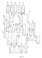
- Fig. 1 is a system block diagram of an automatic manual transmission (hereinafter, AMT) and its peripheral devices, the AMT adopted as an automatic transmission in a vehicle, such as a motorcycle.
- Fig. 2 is an arrangement relationship diagram showing an engagement relation of each shaft and speed gear in an AMT 16.
- the AMT 16 is a single clutch type transmission device which connects and disconnects a rotational driving force of an engine by a clutch CL disposed on a main shaft (spindle shaft).
- the AMT 16 connected to an engine 11 is drive-controlled by a clutch hydraulic device 17 and an AMT control unit 18 as a transmission control device.
- the engine 11 has a throttle body 19 of a throttle-by-wire type, and the throttle body 19 is provided with a motor 20 for opening and closing the throttle.
- the AMT 16 includes a transmission 21 of six forward speeds, the clutch CL, a shift drum 24, and a shift control motor 25 which rotates the shift drum 24.
- a large number of gears which constitute the transmission 21 are bonded to or loosely fitted with a main shaft 26 and a counter shaft 27.
- the main shaft 26 and the counter shaft 27 are provided with the speed gears which can be freely displaced in an axial direction of the main shaft 26 and in an axial direction of the counter shaft 27. End portions of shift forks 29 are engaged with guide grooves formed in the shift drum 24 and the speed gears.
- a primary driving gear 31 is bonded to an output shaft of the engine 11, i.e., a crankshaft 30, and this primary driving gear 31 is engaged with a primary driven gear 32.
- the primary driven gear 32 is connected to the main shaft 26 via the clutch CL.
- the AMT 16 includes a main-shaft rotational-speed sensor 65 which detects a rotational speed of the main shaft 26 by measuring the rotational speed of a predetermined speed gear on the counter shaft 27.
- a driving sprocket 35 is bonded to the counter shaft 27, and a driving force is transmitted to a rear wheel as a drive wheel via a drive chain (now shown) which is wound and hung around this driving sprocket 35.
- a primary-driven-gear rotational-speed sensor 36 which is disposed so as to face an outer circumference of the primary driven gear 32; a gear position sensor 38 which detects a gear position of the transmission 21 on the basis of the rotation position of the shift drum 24; a shifter switch 64 which detects a rotating position of a shifter that is driven by the shift control motor 25; and a neutral switch 63 which detects that the shift drum 24 is at a neutral position.
- a throttle opening sensor 47 which detects a throttle opening is provided in the throttle body 19.
- an output signal from the primary-driven-gear rotational-speed sensor 36 may be detected as an engine speed.
- the clutch hydraulic device 17 has a structure in which a lubricant of the engine 11 is also used as a hydraulic fluid for driving the clutch CL.
- the clutch hydraulic device 17 includes an oil tank 39, and a pipe line 40 for supplying and feeding the oil (hydraulic fluid) in this oil tank 39 to the clutch CL.
- On the pipe line 40 provided are: a hydraulic pump 41 as an oil pressure supply source; and a valve (electromagnetic control valve) 42 as an actuator.
- a regulator 44 which maintains the pressure of oil supplied to the valve 42 at a constant value.
- the valve 42 is provided with a return pipe line 45 of oil.
- a pipe line which connects the valve 42 to the clutch CL is provided with an oil pressure sensor 66 which measures an oil pressure generated in this pipe line, i.e., an oil pressure generated in the clutch CL.
- the pipe line 40 which connects the hydraulic pump 41 to the valve 42 is provided with a main oil pressure sensor 77 and an oil temperature sensor 78 as oil temperature detection means.
- the AMT control unit 18 is connected to a mode switch 49 which switches between an automatic transmission (AT) mode and a manual transmission (MT) mode, and a shift select switch 50 which performs shift indication of shift up (UP) or shift down (DN).
- the AMT control unit 18 includes a central processing unit (CPU), controls the valve 42 and the shift control motor 25 in response to the output signals from the above-described sensors and switches, and can switch the speed stage of the AMT 16 automatically or semiautomatically.
- CPU central processing unit
- the AMT control unit 18 switches the speed stage automatically according to information, such as the vehicle speed, the engine speed, and the throttle opening, when the AT mode is selected. On the other hand, the AMT control unit 18 shifts up or shifts down the transmission 21 with operation of the shift select switch 50, when the MT mode is selected. Furthermore, even when the MT mode is selected, an auxiliary automatic transmission control can be performed for preventing an overspeed and a stall of the engine.
- an oil pressure is applied to the valve 42 by the hydraulic pump 41.
- This oil pressure is controlled by the regulator 44 so that the oil pressure may not exceed an upper limit value.
- the valve 42 is opened by the command from the AMT control unit 18, the oil pressure is applied to the clutch CL, and the primary driven gear 32 is connected to the main shaft 26 via the clutch CL.
- the clutch CL is energized, by a return spring (now shown) incorporated therein, in the direction so that the connection to the main shaft 26 can be cut off.
- the valve 42 which drives the clutch by opening and closing the pipe line connecting the pipe line 40 to the clutch CL is structured so that the AMT control unit 18 can change arbitrarily the time or the like from a full close state to a full open state of the pipe line, on the basis of a drive signal.
- the shift control motor 25 rotates the shift drum 24 according to the command from the AMT control unit 18.
- the shift fork 29 is displaced in an axial direction of the shift drum 24 according to the shape of the guide grooves formed in the outer circumference of the shift drum 24.
- the gear engagement on the counter shaft 27 and the main shaft 26 changes, and the shift up or the shift down of the transmission is performed.
- the main shaft 26 which is connected to the clutch CL supports driving-side gears M1-M6 of the paired speed gears.
- the first speed driving gear M1 is attached non-slidably in the axial direction and rotatably in the circumferential direction.
- the second speed driving gear M2 is formed to the main shaft 26 integrally.
- the third speed driving gear M3 and the fourth speed driving gear M4 which is integral therewith are attached slidably in the axial direction and non-rotatably in the circumferential direction.
- the fifth speed driving gear M5 and the sixth speed driving gear M6 are attached non-slidably in the axial direction and rotatably in the circumferential direction.
- the counter shaft 27 supports driven gears C1-C6 which engage with the driving gears M1-M6.
- the first to fourth speed driven gears C1-C4 attached non-slidably in the axial direction and rotatably in the circumferential direction.
- the fifth and sixth speed driven gears C5 and C6 are attached slidably in the axial direction and non-rotatably in the circumferential direction.
- the driving gears M3 and M4 and the driven gears C5 and C6, i.e., gears which are slidable in the axial direction, among the above-described gear train, are slid by the shift forks 29. Accordingly, the shifting operation is performed by connecting and disconnecting a dog clutch.
- the AMT 16 which is not part of the present invention, includes a main shaft brake 60 as brake means which can apply a certain brake force (damping force) to the main shaft 26.
- the main shaft brake 60 is a friction type brake which is operated by a driving command from the AMT control unit 18, and which is composed of: a disc-like braked member 61 fixed to an end portion of the main shaft 26; and a braking member 62 which contacts the braked member 61.
- the brake means 60 may be composed of an electromagnetic brake or the like.
- Fig. 3 is a block diagram showing a structure of the AMT control unit 18 and its peripheral devices.
- the same numerals as the above show the same or equivalent components.
- the AMT control unit 18 includes a transmission control unit 100 in which a shift map 101 is stored.
- the transmission control unit 100 including clutch control means drives the shift control motor 25 and the valve 42 and performs the shifting operation, during normal running of a vehicle, on the basis of the gear position sensor 38, an engine speed sensor 90, the throttle opening sensor 47, a vehicle speed sensor 91, and vehicle speed information, and according to the shift map 101 which is a three-dimensional map or the like.
- the engine speed may be detected on the basis of the output signal from the primary-driven-gear rotational-speed sensor 36.
- the AMT control unit 18 can detect engagement start timing when the clutch CL is connected.
- the primary-driven-gear rotational-speed sensor 36 detects a rotational speed of the primary driven gear 32 serving as an input side rotating body
- the main-shaft rotational-speed sensor 65 detects a rotational speed of the main shaft 26 serving as an output side rotating body. It is structured that: the primary-driven-gear rotational-speed sensor 36 detects a rotational speed of the input side with respect to the clutch CL; and the main-shaft rotational-speed sensor 65 detects a rotational speed of the output side.
- a predetermined value for example, 50 rpm
- Clutch-engagement-start detection means 120 detects that the clutch CL starts to be engaged on the basis of output information from the main-shaft rotational-speed sensor 65 and the primary-driven-gear rotational-speed sensor 36. Note that, the detection of the engagement start is performed by detecting that the main shaft 26 and the primary driven gear 32 synchronously rotate when the clutch CL is driven in a direction so that the clutch CL can be connected from a state where the clutch CL is disconnected. Accordingly, the detection is set to be performed when the transmission 21 is at a neutral position in this embodiment in which the AMT 16 is of the single clutch type.
- the clutch-engagement-start detection means 120 drive-controls the main shaft brake 60 so that the main shaft 26 is temporarily stopped. This is because, due to a viscosity of the lubricant or various kinds of friction, the main shaft 26 tends to rotate together with the clutch side even in a state where the clutch CL is disconnected. Accordingly, it is structured that: the main shaft brake 60 stops the main shaft 26 temporarily to create a state where an engagement start is suitably detected; and that the clutch CL is then caused to drive in the connection direction.
- the main shaft brake 60 at the time when the clutch is caused to drive in the connection direction is made into a state where the main shaft brake 60 is opened completely, and also can be made into a state where the main shaft brake 60 is continued to be applied with a predetermined damping force in order to prevent the rotation due to the viscosity of the lubricant, or the like.
- the magnitude of the damping force at this time can be arbitrarily set depending on the magnitude of friction, or the like.
- the speed at which the clutch CL is driven in the connection direction can also be set arbitrarily.
- Clutch-control-amount detection means 150 detects a control amount (oil pressure) of the clutch CL on the basis of output information from the clutch-oil-pressure sensor 66. Furthermore, clutch-engagement-start control-amount detection means 110 detects a control amount of the clutch CL at the time when the engagement is started, on the basis of output signals from the clutch-engagement-start detection means 120 and the clutch-control-amount detection means 150.
- clutch-correction-control-amount deriving means 130 On the basis of the output signals from the clutch-engagement-start detection means 120 and the clutch-control-amount detection means 150, clutch-correction-control-amount deriving means 130 detects a control amount (oil pressure) at the time when the clutch CL starts to be engaged, and inputs this control amount into a clutch control correction amount data table 140 so that a control correction amount is derived. As shown in Fig. 5 , the clutch control correction amount data table 140 is configured so that a control correction amount H with respect to an oil pressure P may be determined on one-by-one basis. Furthermore, the clutch-correction-control-amount deriving means 130 transmits the derived control correction amount H to the transmission control unit 100. The transmission control unit 100 feedback-controls the clutch CL on the basis of the transmitted control correction amount H.
- the clutch-engagement-start control-amount detection means 110 is structured so that, when a control amount of the clutch until the main shaft 26 and the primary driven gear 32 synchronously rotate exceeds a predetermined control amount, a rider may be informed that the control amount until the clutch starts to be engaged has become large by using warning means 92 composed of a warning light, a speaker, and the like. Accordingly, the rider is urged to take an action, for example, exchanging a worn-out clutch plate.
- Fig. 4 is a flowchart showing a flow of a clutch-engagement-start detection control according to this embodiment. This series of controls is performed while a vehicle is stopped.
- Step S1 an output signal of the main-shaft rotational-speed sensor 65 is detected.
- Step S2 an output signal of the primary-driven-gear rotational-speed sensor 36 is detected.
- Step S3 an output signal of the clutch-oil-pressure sensor 66 is detected.
- the control progresses to Step S5, and the rotation of the main shaft 26 is made to stop temporarily by driving the main shaft brake 60. Accordingly, a preparation for detecting an engagement start of a clutch is completed. Meanwhile, when a negative determination is made at Step S4, the control returns to Step S 1.
- Step S6 the main shaft brake 60 is driven for a predetermined period by a predetermined pressure, and the brake operation is held.
- the predetermined period and the magnitude of the brake force for holding the brake operation can be arbitrarily set depending on the friction with which the main shaft 26 tends to rotate.
- Step S7 the main shaft brake 60 is released, and the clutch CL is driven in the connection direction at Step S8.
- Step S9 it is determined whether or not the rotational speed of the main shaft 26 detected by the main-shaft rotational-speed sensor 65 is synchronized with the rotational speed of the primary driven gear 32 detected by the primary-driven-gear rotational-speed sensor 36.
- the rotational speeds are determined to be synchronized when the rotational speed difference becomes equal to or less than a predetermined value (for example, 1 m/s). According to this setting, while accuracy variation or the like of each rotational-speed sensor is taken into consideration, a synchronized rotational speed can be detected.
- a predetermined value for example, 1 m/s
- Step S9 the oil pressure value detected by the clutch-oil-pressure sensor 66 at the time of synchronous rotation is memorized as a control amount of the clutch at Step S10.
- Step S9 the control returns to Step S7.
- control correction amount H is derived on the basis of the oil pressure-clutch control correction amount data table 140. Then, at Step S12, the clutch CL is feedback-controlled on the basis of the control correction amount H, and the series of the controls ends.
- the clutch is always controlled by using the oil pressure-clutch control correction amount data table 140 in the above-described flowchart, such feedback control may be performed only when the control amount detected at the time of the engagement start and a predetermined reference control amount are compared, and concurrently when a difference between the amounts is greater than a predetermined value.
- the detection of the engagement start of the clutch can be periodically performed during a period from starting an engine before the vehicle starts moving or at a predetermined cycle memorized by the AMT. This predetermined cycle can be changed at any time on the basis of various kinds of information, such as an oil temperature.
- control correction amount is detected on the basis of the oil pressure applied to the clutch CL
- control correction amount may be detected on the basis of a drive current value of the valve 42 as an actuator which controls a supply amount of the hydraulic fluid to the clutch CL.
- the clutch control device even when the output side rotating body and the input side rotating body tend to rotate together in a state where the clutch is disconnected, by making the output side rotating body stop temporarily by the brake means, it becomes possible to accurately detect timing when a rotational speed difference between the two becomes equal to or less than a predetermined value. Accordingly, this makes it possible to accurately detect a state of the engagement start of the clutch, and to perform a suitable feedback control.
- the AMT 16 includes the main shaft brake 60 which applies a damping force to the main shaft 26.
- the main shaft brake 60 applies a damping force to the main shaft 26.
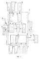
- Fig. 6 is a system block diagram of an AMT 16a and its peripheral devices according to an embodiment of the present invention.
- the same numerals as the above show the same or equivalent components.
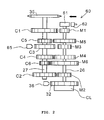
- Fig. 7 is an arrangement relationship diagram showing an engagement relation of each shaft and speed gear in the AMT 16a.
- the AMT 16a is structured as a twin clutch type transmission device which connects and disconnects a rotational driving force of the engine with two clutches disposed on the main shaft. Since the whole structure except the twin clutch and the twin clutch drive control unit is the same as that of the above-described embodiment, details thereof will be omitted.
- the AMT 16a includes the transmission 21 of the six forward speeds, a first clutch CL1, a second clutch CL2, the shift drum 24, and the shift control motor 25 which rotates the shift drum 24.
- a large number of gears which constitute the transmission 21 are bonded to or loosely fitted with the main shaft 26 and the counter shaft 27.
- the main shaft 26 includes an inner main shaft 26a and an outer main shaft 26b which are pivotally supported and rotatable with respect to each other.
- the inner main shaft 26a is bonded to the first clutch CL1, and the outer main shaft 26b is bonded to the second clutch CL2.
- the main shaft 26 and the counter shaft 27 are provided with the speed gears which can be freely displaced in an axial direction of the main shaft 26 and in an axial direction of the counter shaft 27. End portions of shift forks 23 are engaged with guide grooves formed in the shift drum 24 and the speed gears.
- the primary driving gear 31 is bonded to the output shaft of the engine 11, i.e., the crankshaft 30, and this primary driving gear 31 is engaged with the primary driven gear 32.
- the primary driven gear 32 is connected to the inner main shaft 26a via the first clutch CL1, and is connected to the outer main shaft 26b via the second clutch CL2.
- the AMT 16a includes an inner-main-shaft rotational-speed sensor 73 and an outer-main-shaft rotational-speed sensor 74 which detect rotational speeds of the inner main shaft 26a and the outer main shaft 26b, respectively, by measuring the rotational speed of a predetermined speed gear on the counter shaft 27.
- Valves as an actuator is composed of a first valve 42a and a second valve 42b which can apply oil pressures to the first clutch CL1 and the second clutch CL2 individually. Each of the valves is provided with the return pipe line 45 of oil.
- a pipe line which connects the first valve 42a to the first clutch CL1 is provided with a first-clutch-oil-pressure sensor 75 which measures an oil pressure generated in the first clutch CL1.
- a pipe line which connects the second valve 42b to the second clutch CL2 is provided with a second-clutch-oil-pressure sensor 76 which measures an oil pressure generated in the second clutch CL2.
- an oil pressure is applied to the valve 42 by the hydraulic pump 41.
- This oil pressure is controlled by the regulator 44 so that the oil pressure may not exceed an upper limit value.
- the valve 42a or the valve 42b is opened by the command from the AMT control unit 18, the oil pressure is applied to the first clutch CL1 or the second clutch CL2, and the primary driven gear 32 is connected to the inner main shaft 26a or the outer main shaft 26b via the first clutch CL1 or the second clutch CL2.
- the first clutch CL1 and the second clutch CL2 are energized, by return springs incorporated therein, in the direction so that the connections to the inner main shaft 26a and the outer main shaft 26b can be cut off.
- the shift control motor 25 rotates the shift drum 24 according to the command from the AMT control unit 18.
- the shift drum 24 rotates, the shift fork 23 is displaced in the axial direction of the shift drum 24 according to the shape of the guide grooves formed in the outer circumference of the shift drum 24.
- the gear engagement on the counter shaft 27 and the main shaft 26 changes, and the shift up or the shift down of the transmission is performed.
- the AMT 16a is structured so that the inner main shaft 26a bonded to the first clutch CL1 may support odd-numbered speed gears (first, third, and fifth speed) and the outer main shaft 26b bonded to the second clutch CL2 may support even-numbered speed gears (second, fourth, and sixth speed). Therefore, for example, during running in the odd-numbered speed gear, an oil pressure supply to the first clutch CL1 is continued, and a connected state is maintained. Furthermore, while a shift change is performed, it becomes possible, by changing the gear engagement in advance by the rotation of the shift drum 24, to complete the shifting operation only by switching the connected states of the two clutches.
- the inner main shaft 26a which is connected to the first clutch CL1 supports the driving gears M1, M3, and M5 of the odd-numbered speed stage.
- the first speed driving gear M1 is formed to the inner main shaft 26a integrally.
- the third speed driving gear M3 is attached slidably in the axial direction and non-rotatably in the circumferential direction.
- the fifth speed driving gear M5 is attached non-slidably in the axial direction and rotatably in the circumferential direction.
- the outer main shaft 26b which is connected to the second clutch CL2 supports the driving gears M2, M4, and M6 of the even-numbered speed stage.
- the second speed driving gear M2 is formed to the outer main shaft 26b integrally.
- the fourth speed driving gear M4 is attached slidably in the axial direction and non-rotatably in the circumferential direction.
- the sixth speed driving gear M6 is attached non-slidably in the axial direction and rotatably in the circumferential direction.
- the counter shaft 27 supports the driven gears C1-C6 which engage with the driving gears M1-M6.
- the first to the fourth speed driven gears C1-C4 are attached non-slidably in the axial direction and rotatably in the circumferential direction.
- the fifth and sixth speed driven gears C5 and C6 are attached slidably in the axial direction and non-rotatably in the circumferential direction.
- the driving gears M3 and M4 and the driven gears C5 and C6, i.e., gears which are slidable in the axial direction, among the above-described gear train, are slid by the shift forks 23. Accordingly, the shifting operation is performed by connecting and disconnecting a dog clutch.
- the AMT 16a includes an inner main shaft brake 70 and an outer main shaft brake 80 in the inner main shaft 26a and the outer main shaft 26b, respectively.
- the inner main shaft brake 70 which applies a damping force to the inner main shaft 26a is composed of: a disk-like braked member 71 fixed to the inner main shaft 26a; and a braking member 72 which contacts the braked member 71.
- the outer main shaft brake 80 which applies a damping force to the outer main shaft 26b is composed of: a disk-like braked member 81 fixed to the outer main shaft 26b; and a braking member 82 which contacts the braked member 81.
- the rotational driving force of the engine which is transmitted to the primary driven gear 32 from the crankshaft 30, is transmitted to the inner main shaft 26a by connecting the first clutch CL1 thereto.
- the rotational driving force is transmitted to the counter shaft 27 via the first speed driven gear C1 from the first speed driving gear M1.
- a dog clutch for the first speed is in a state of being engaged between the first speed driven gear C1 and the fifth speed driven gear C5.
- the AMT 16a can execute "preliminary shifting" which prepares a speed change for the second speed by engaging a dog clutch for the second speed, i.e., the dog clutch between the sixth speed driven gear C6 and the second speed driven gear C2.
- a dog clutch for the second speed i.e., the dog clutch between the sixth speed driven gear C6 and the second speed driven gear C2.
- the rotational driving force of the engine since the second clutch CL2 is disconnected, even if the dog clutch for the second speed is engaged during running in the first speed gear, the rotational driving force of the engine only makes the outer main shaft 26b run idle with the second speed driving gear M2.
- the rotational driving force can be outputted instantly without interruption from the counter shaft via the second speed gear.
- the shift drum 24 of the AMT 16a is set to have a position of "waiting for neutral" between each of predetermined rotating positions for selecting each speed stage.
- a group of gears not transmitting the rotational driving force, among groups of the even-numbered speed gears and the odd-numbered speed gears is made to be in a neutral state. For this reason, it is possible to make the odd-numbered speed gear into the neutral state during running in the even-numbered speed gear, as well as to make the even-numbered speed gear into the neutral state during running in the odd-numbered speed gear.
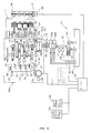
- Fig. 8 is a block diagram showing a structure of the AMT control unit 18 and its peripheral devices according to the embodiment of the present invention.
- the same numerals as the above show the same or equivalent components.
- the present embodiment is the same as the embodiment described above except that: the valves which drive the first clutch CL1 and the second clutch CL2 are composed of the first valve 42a and the second valve 42b; and the present embodiment includes the inner-main-shaft rotational-speed sensor 73 and the outer-main-shaft rotational-speed sensor 74 as well as the inner main shaft brake 70 which brakes the inner main shaft 26a and the outer main shaft brake 80 which brakes the outer main shaft 26b. Accordingly, detailed explanations thereof will be omitted.
- the AMT control unit 18 can detect each engagement start timing when both of the clutches CL1 and CL2 are connected.
- the inner-main-shaft rotational-speed sensor 73 detects a rotational speed of the output side with respect to the first clutch CL1.
- the outer-main-shaft rotational-speed sensor 74 detects a rotational speed of the output side with respect to the second clutch CL2.
- the primary-driven-gear rotational-speed sensor 36 detects each rotational speed of the input side of each clutch.
- detection of the engagement start of the clutch is performed by detecting timing when the inner main shaft 26a or the outer main shaft 26b and the primary driven gear 32 synchronously rotate, when the first clutch CL1 or the second clutch CL2 is driven in the connection direction gradually after the first clutch CL1 or the second clutch CL2 is disconnected.
- the detection of the engagement start can be performed on a side among the first clutch CL1 or the second clutch CL2 being disconnected.
- the detection of the engagement start can be performed on the first clutch CL1 during running in the even-numbered speed gear, and the detection of the engagement start can be performed on the second clutch CL2 during running in the odd-numbered speed gear.
- the detection can be performed alternatively on the first clutch CL1 and the second clutch CL2.
- the clutch-engagement-start detection means 120 drive-controls the inner main shaft brake 70 when detecting the engagement start of the first clutch CL1, and drive-controls the outer main shaft brake 80 when detecting the engagement start of the second clutch CL2. Furthermore, when the engagement start of the clutch is detected, the inner main shaft brake 70 or the outer main shaft brake 80 is made into a completely open state, and also can be made into a state where the inner main shaft brake 70 or the outer main shaft brake 80 is continued to be applied with a predetermined damping force in order to prevent rotation due to the viscosity of the lubricant of the clutch, friction generated between the inner main shaft 26a and the outer main shaft 26b, or the like. This magnitude of the damping force can be arbitrarily set depending on the magnitude of friction, or the like.
- the clutch-control-amount detection means 150 detects a control amount of each of the first clutch CL1 and the second clutch CL2 on the basis of output information from the first-clutch-oil-pressure sensor 75 and the second-clutch-oil-pressure sensor 76. Furthermore, the clutch-engagement-start control-amount detection means 110 detects each of the control amount at the time when the clutch starts to be engaged on the basis of output signals from the clutch-engagement-start detection means 120 and the clutch-control-amount detection means 150.
- the clutch-correction-control-amount deriving means 130 On the basis of the output signals from the clutch-engagement-start detection means 120 and the clutch-control-amount detection means 150, the clutch-correction-control-amount deriving means 130 detects a control amount (oil pressure) at the time when each of the clutches starts to be engaged, and inputs this control amount into the clutch control correction amount data table 140 so that a control correction amount is derived.
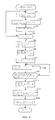
- Fig. 9 is a flowchart showing a flow of a clutch-engagement-start detection control according to the embodiment of the present invention. Note that, at the time of detecting the engagement start of a clutch, the flow until the clutch is driven in the connection direction after the main shaft is stopped temporarily to detect synchronous timing of the rotational speed, and a control correction amount is derived on the basis of the control amount at the time when the engagement start is detected, is the same as that in the case of the single clutch type explained in Fig. 4 . Accordingly, in the AMT 16a of the twin clutch type, here description will be given mainly of which order is used to perform detection of an engagement start with respect to the first clutch CL1 and the second clutch CL2.
- Steps S20-24 output signals of the inner-main-shaft rotational-speed sensor 73, the outer-main-shaft rotational-speed sensor 74, the primary-driven-gear rotational-speed sensor 36, the first-clutch-oil-pressure sensor 75, and the second-clutch-oil-pressure sensor 76 are detected, respectively.
- Step S25 it is detected whether or not the shift drum 24 is at a neutral position.
- the neutral positions here refers to a rotating position where both of an even-numbered speed gear and an odd-numbered speed gear are in a neutral state, and where the above-described neutral switch 63 is set to ON.
- AT automatic transmission
- Step S26 the inner main shaft brake 70 is driven to derive a control correction amount of the first clutch CL1.
- Step S27 the outer main shaft brake 80 is driven to derive a control correction amount of the second clutch CL2. Then, the control progresses to Step S33, and both of the clutches are feedback-controlled. Thus, this series of controls ends. Note that, when an affirmative determination is made at Step S25, detection of the engagement start may be started from the second clutch CL2.
- Step S25 when a negative determination is made at Step S25, the control progresses to Step S28 assuming that the vehicle is running. Then, a determination is made whether or not a speed gear is in the even-numbered speed.
- Step S28 the control progresses to Step S29, and the outer main shaft brake 80 is driven to detect an engagement start, and a control correction amount of the second the clutch CL2 is derived.
- Step S31 it is determined whether or not one step shifting is made.
- the control progresses to Step S32 assuming that the gear has been shifted to the even-numbered speed gear.
- Step S32 the inner main shaft brake 70 is driven to derive a control correction amount of the first clutch CL1. Accordingly, the control correction amounts of both the clutches CL1 and CL2 are derived.
- the control progresses to Step S33, and a feedback control is performed.
- the series of controls ends.
- Step S31 the control progresses to Step S33, and the feedback control is performed.
- a control correction amount of the first clutch CL1 is derived when a next detection preparation is completed. Furthermore, the clutch control resulting from the control correction amount may be promptly performed, when any one of the control correction amounts is derived.
- Step S30 when a negative determination is made at Step S28, i.e., when the speed stage is determined to be in the odd-numbered speed, the control progresses to Step S30.
- the inner main shaft brake 70 is driven to derive a control correction amount of the first clutch CL1.
- Step S34 it is determined whether or not one step shifting is made.
- the control progresses to Step S35 assuming that the gear has been shifted to the odd-numbered speed gear.
- Step S35 the outer main shaft brake 80 is driven to derive a control correction amount of the second clutch CL2. Accordingly, the control correction amounts of both the clutches CL1 and CL2 are derived.
- the control progresses to Step S33, and a feedback control is performed.
- Step S34 the control progresses to Step S33.
- a control correction amount of the second clutch CL2 is derived when a next detection preparation for an engagement start is completed. It should be noted that, in the present embodiment also, a predetermined time and a magnitude of the brake for driving the inner main shaft brake 70 and the outer main shaft brake 80 can be set arbitrarily depending on friction or the like.
- the clutch control device by performing detection of an engagement start of a clutch with respect to the first clutch CL1 and the second clutch CL2 alternatively, a state of the engagement start of both the clutches is detected even while a vehicle is running. Even when the state of the engagement start of the clutch is changed while the vehicle is running, it becomes possible to update a correction amount of a clutch control as required to feedback on the control of the clutch.
- the clutch control device even when the output side rotating body and the input side rotating body tend to rotate together in a state where the clutch is disconnected, by making the output side rotating body stop temporarily by the brake means, it becomes possible to accurately detect timing when a rotational speed difference between the output side rotating body and the input side rotating body becomes equal to or less than a predetermined value. Accordingly, an engagement of the clutch can be detected accurately, and a suitable feedback control can be performed.
- structures of the twin clutch type transmission device, brake means, and rotational speed detection means for the input side rotating body and the output side rotating body of the clutch are not limited to the above-described embodiment.
- a clutch control device according to the present invention may be adopted, without limitation to a motorcycle, in a tricycle, a four-wheeled vehicle, and the like.
Landscapes
- Physics & Mathematics (AREA)
- Fluid Mechanics (AREA)
- Engineering & Computer Science (AREA)
- General Engineering & Computer Science (AREA)
- Mechanical Engineering (AREA)
- Hydraulic Clutches, Magnetic Clutches, Fluid Clutches, And Fluid Joints (AREA)
- Control Of Transmission Device (AREA)
Applications Claiming Priority (1)
| Application Number | Priority Date | Filing Date | Title |
|---|---|---|---|
| JP2008088032A JP5162767B2 (ja) | 2008-03-28 | 2008-03-28 | クラッチ制御装置 |
Publications (2)
| Publication Number | Publication Date |
|---|---|
| EP2105625A1 EP2105625A1 (en) | 2009-09-30 |
| EP2105625B1 true EP2105625B1 (en) | 2014-08-27 |
Family
ID=40810619
Family Applications (1)
| Application Number | Title | Priority Date | Filing Date |
|---|---|---|---|
| EP09153083.2A Ceased EP2105625B1 (en) | 2008-03-28 | 2009-02-18 | Clutch control device |
Country Status (3)
| Country | Link |
|---|---|
| US (1) | US8272994B2 (enExample) |
| EP (1) | EP2105625B1 (enExample) |
| JP (1) | JP5162767B2 (enExample) |
Families Citing this family (13)
| Publication number | Priority date | Publication date | Assignee | Title |
|---|---|---|---|---|
| JP5374726B2 (ja) * | 2008-03-31 | 2013-12-25 | 本田技研工業株式会社 | クラッチ制御装置およびμ補正係数算出方法 |
| JP5620671B2 (ja) * | 2009-11-24 | 2014-11-05 | ヤマハ発動機株式会社 | 変速装置 |
| DE102010014198A1 (de) * | 2010-04-08 | 2011-10-13 | Schaeffler Technologies Gmbh & Co. Kg | Verfahren zur Steuerung einer Doppelkupplung |
| WO2011124197A1 (de) * | 2010-04-08 | 2011-10-13 | Schaeffler Technologies Gmbh & Co. Kg | Verfahren zum steuern einer automatisierten kupplung |
| JP5501083B2 (ja) * | 2010-04-28 | 2014-05-21 | アイシン・エーアイ株式会社 | 車両の動力伝達制御装置 |
| JP5733022B2 (ja) * | 2011-05-24 | 2015-06-10 | スズキ株式会社 | ツインクラッチ式自動変速機の制御装置 |
| JP5918946B2 (ja) * | 2011-08-29 | 2016-05-18 | アイシン・エーアイ株式会社 | 車両の動力伝達制御装置 |
| JP5929924B2 (ja) * | 2012-01-31 | 2016-06-08 | トヨタ自動車株式会社 | 車両の操舵制御装置 |
| JP5931607B2 (ja) * | 2012-06-29 | 2016-06-08 | 三菱重工業株式会社 | 遠心クラッチおよびそれを用いた冷凍・空調装置 |
| JP5883755B2 (ja) * | 2012-09-28 | 2016-03-15 | 本田技研工業株式会社 | ツインクラッチ制御装置 |
| JP6137706B2 (ja) * | 2015-03-19 | 2017-05-31 | 本田技研工業株式会社 | 車両のサスペンション制御装置 |
| US9850965B2 (en) * | 2016-05-03 | 2017-12-26 | Ford Global Technologies, Llc | Method for operating an automatic start/stop system in a vehicle utilizing a fluid launch clutch |
| DE102019205508A1 (de) * | 2019-04-16 | 2020-10-22 | Zf Friedrichshafen Ag | Hybrid-Getriebeeinrichtung, Motor-Getriebeanordnung, Hybrid-Antriebsstrang sowie Kraftfahrzeug |
Citations (1)
| Publication number | Priority date | Publication date | Assignee | Title |
|---|---|---|---|---|
| US20070199395A1 (en) * | 2006-02-28 | 2007-08-30 | Hitachi, Ltd. | Control apparatus and control method for vehicle |
Family Cites Families (13)
| Publication number | Priority date | Publication date | Assignee | Title |
|---|---|---|---|---|
| DE3690165T1 (enExample) * | 1985-03-29 | 1987-06-04 | ||
| US4899858A (en) * | 1989-03-02 | 1990-02-13 | Eaton Corporation | Method and control system for updating of control parameter value indicative of master clutch point of incipient engagement |
| US5337868A (en) * | 1992-01-02 | 1994-08-16 | Eaton Corporation | Touch point identification for automatic clutch controller |
| CA2085517C (en) | 1992-01-02 | 1999-04-13 | Chia-Hsiang Liu | Touch point identification for automatic clutch controller |
| US5393274A (en) * | 1993-07-19 | 1995-02-28 | Eaton Corporation | Touch point identification algorithm for automatic clutch controller |
| US6022295A (en) * | 1998-11-12 | 2000-02-08 | Eaton Corporation | Touch point identification for vehicle master clutch |
| JP2001241545A (ja) * | 2000-03-01 | 2001-09-07 | Unisia Jecs Corp | クラッチ制御装置 |
| JP4566399B2 (ja) * | 2000-12-15 | 2010-10-20 | 株式会社小松製作所 | クラッチの調整方法およびその装置 |
| US6427550B1 (en) * | 2001-01-12 | 2002-08-06 | New Venture Gear, Inc. | Twin clutch automated transaxle |
| KR100857686B1 (ko) * | 2001-01-24 | 2008-09-08 | 루크 라멜렌 운트 쿠플룽스바우베타일리궁스 카게 | 자동차의 자동 클러치를 제어하기 위한 방법 |
| JP2004197842A (ja) | 2002-12-18 | 2004-07-15 | Aisin Seiki Co Ltd | クラッチ制御装置 |
| JP4135688B2 (ja) * | 2004-06-29 | 2008-08-20 | トヨタ自動車株式会社 | ハイブリッド車両のクラッチ滑り検出方法 |
| DE102007025501A1 (de) * | 2007-06-01 | 2008-12-04 | Zf Friedrichshafen Ag | Verfahren und Vorrichtung zur Steuerung einer Kupplung |
-
2008
- 2008-03-28 JP JP2008088032A patent/JP5162767B2/ja not_active Expired - Fee Related
-
2009
- 2009-02-13 US US12/370,957 patent/US8272994B2/en active Active
- 2009-02-18 EP EP09153083.2A patent/EP2105625B1/en not_active Ceased
Patent Citations (1)
| Publication number | Priority date | Publication date | Assignee | Title |
|---|---|---|---|---|
| US20070199395A1 (en) * | 2006-02-28 | 2007-08-30 | Hitachi, Ltd. | Control apparatus and control method for vehicle |
Also Published As
| Publication number | Publication date |
|---|---|
| JP2009243502A (ja) | 2009-10-22 |
| US8272994B2 (en) | 2012-09-25 |
| JP5162767B2 (ja) | 2013-03-13 |
| US20090247362A1 (en) | 2009-10-01 |
| EP2105625A1 (en) | 2009-09-30 |
Similar Documents
| Publication | Publication Date | Title |
|---|---|---|
| EP2105625B1 (en) | Clutch control device | |
| EP2273145B1 (en) | CLUTCH CONTROL DEVICE AND µ-CORRECTION FACTOR CALCULATING METHOD | |
| JP4895996B2 (ja) | ツインクラッチ式変速装置 | |
| JP5153525B2 (ja) | クラッチ制御装置 | |
| JP5181237B2 (ja) | 車両の変速制御装置 | |
| EP1947359B1 (en) | Clutch engagement controller and vehicle having the same | |
| JP5200272B2 (ja) | クラッチ制御装置 | |
| EP2653754B1 (en) | Control device for dual clutch transmission and control method for dual clutch transmission | |
| EP3175149B1 (en) | Control apparatus for vehicle | |
| EP2143966B1 (en) | Shift control device and vehicle | |
| JP4934859B2 (ja) | 変速機のクラッチ制御装置 | |
| EP2653753B1 (en) | Control device for dual clutch transmission and control method for dual clutch transmission | |
| EP1319856A1 (en) | Vehicle power transmission device | |
| JP5914101B2 (ja) | 自動二輪車用ツインクラッチ式自動変速機の変速制御装置 | |
| EP2713079A1 (en) | Twin clutch controlling apparatus | |
| JP5926222B2 (ja) | 伝動装置 | |
| JP3630072B2 (ja) | 車両用自動変速機のクリープ力制御装置 | |
| JP3752959B2 (ja) | 機械式自動変速機の変速制御装置 | |
| CN108700187A (zh) | 双离合式变速器的控制装置 | |
| JP2009180351A (ja) | クラッチ接続状態検知装置 |
Legal Events
| Date | Code | Title | Description |
|---|---|---|---|
| PUAI | Public reference made under article 153(3) epc to a published international application that has entered the european phase |
Free format text: ORIGINAL CODE: 0009012 |
|
| AK | Designated contracting states |
Kind code of ref document: A1 Designated state(s): AT BE BG CH CY CZ DE DK EE ES FI FR GB GR HR HU IE IS IT LI LT LU LV MC MK MT NL NO PL PT RO SE SI SK TR |
|
| AX | Request for extension of the european patent |
Extension state: AL BA RS |
|
| 17P | Request for examination filed |
Effective date: 20100326 |
|
| AKX | Designation fees paid |
Designated state(s): DE FR IT |
|
| 17Q | First examination report despatched |
Effective date: 20121109 |
|
| GRAP | Despatch of communication of intention to grant a patent |
Free format text: ORIGINAL CODE: EPIDOSNIGR1 |
|
| RAP1 | Party data changed (applicant data changed or rights of an application transferred) |
Owner name: HONDA MOTOR CO., LTD. |
|
| INTG | Intention to grant announced |
Effective date: 20140320 |
|
| RIN1 | Information on inventor provided before grant (corrected) |
Inventor name: FUKAYA, KAZUYUKI Inventor name: NEDACHI, YOSHIAKI Inventor name: OZEKI, TAKASHI Inventor name: TSUKADA, YOSHIAKI Inventor name: KOJIMA, HIROYUKI |
|
| GRAS | Grant fee paid |
Free format text: ORIGINAL CODE: EPIDOSNIGR3 |
|
| GRAA | (expected) grant |
Free format text: ORIGINAL CODE: 0009210 |
|
| AK | Designated contracting states |
Kind code of ref document: B1 Designated state(s): DE FR IT |
|
| REG | Reference to a national code |
Ref country code: DE Ref legal event code: R096 Ref document number: 602009026244 Country of ref document: DE Effective date: 20141009 |
|
| REG | Reference to a national code |
Ref country code: DE Ref legal event code: R097 Ref document number: 602009026244 Country of ref document: DE |
|
| PLBE | No opposition filed within time limit |
Free format text: ORIGINAL CODE: 0009261 |
|
| STAA | Information on the status of an ep patent application or granted ep patent |
Free format text: STATUS: NO OPPOSITION FILED WITHIN TIME LIMIT |
|
| 26N | No opposition filed |
Effective date: 20150528 |
|
| REG | Reference to a national code |
Ref country code: FR Ref legal event code: PLFP Year of fee payment: 8 |
|
| REG | Reference to a national code |
Ref country code: FR Ref legal event code: PLFP Year of fee payment: 9 |
|
| REG | Reference to a national code |
Ref country code: FR Ref legal event code: PLFP Year of fee payment: 10 |
|
| PGFP | Annual fee paid to national office [announced via postgrant information from national office to epo] |
Ref country code: FR Payment date: 20190221 Year of fee payment: 13 Ref country code: IT Payment date: 20190221 Year of fee payment: 11 |
|
| REG | Reference to a national code |
Ref country code: DE Ref legal event code: R084 Ref document number: 602009026244 Country of ref document: DE |
|
| PG25 | Lapsed in a contracting state [announced via postgrant information from national office to epo] |
Ref country code: FR Free format text: LAPSE BECAUSE OF NON-PAYMENT OF DUE FEES Effective date: 20200229 |
|
| PGFP | Annual fee paid to national office [announced via postgrant information from national office to epo] |
Ref country code: DE Payment date: 20210202 Year of fee payment: 13 |
|
| PG25 | Lapsed in a contracting state [announced via postgrant information from national office to epo] |
Ref country code: IT Free format text: LAPSE BECAUSE OF NON-PAYMENT OF DUE FEES Effective date: 20200218 |
|
| REG | Reference to a national code |
Ref country code: DE Ref legal event code: R119 Ref document number: 602009026244 Country of ref document: DE |
|
| PG25 | Lapsed in a contracting state [announced via postgrant information from national office to epo] |
Ref country code: DE Free format text: LAPSE BECAUSE OF NON-PAYMENT OF DUE FEES Effective date: 20220901 |