EP2103868A2 - Fahrzeugscheinwerfer - Google Patents
Fahrzeugscheinwerfer Download PDFInfo
- Publication number
- EP2103868A2 EP2103868A2 EP09004044A EP09004044A EP2103868A2 EP 2103868 A2 EP2103868 A2 EP 2103868A2 EP 09004044 A EP09004044 A EP 09004044A EP 09004044 A EP09004044 A EP 09004044A EP 2103868 A2 EP2103868 A2 EP 2103868A2
- Authority
- EP
- European Patent Office
- Prior art keywords
- light distribution
- distribution pattern
- vehicle
- lighting device
- shade
- Prior art date
- Legal status (The legal status is an assumption and is not a legal conclusion. Google has not performed a legal analysis and makes no representation as to the accuracy of the status listed.)
- Granted
Links
Images


Classifications
-
- B—PERFORMING OPERATIONS; TRANSPORTING
- B60—VEHICLES IN GENERAL
- B60Q—ARRANGEMENT OF SIGNALLING OR LIGHTING DEVICES, THE MOUNTING OR SUPPORTING THEREOF OR CIRCUITS THEREFOR, FOR VEHICLES IN GENERAL
- B60Q1/00—Arrangement of optical signalling or lighting devices, the mounting or supporting thereof or circuits therefor
- B60Q1/02—Arrangement of optical signalling or lighting devices, the mounting or supporting thereof or circuits therefor the devices being primarily intended to illuminate the way ahead or to illuminate other areas of way or environments
- B60Q1/04—Arrangement of optical signalling or lighting devices, the mounting or supporting thereof or circuits therefor the devices being primarily intended to illuminate the way ahead or to illuminate other areas of way or environments the devices being headlights
- B60Q1/14—Arrangement of optical signalling or lighting devices, the mounting or supporting thereof or circuits therefor the devices being primarily intended to illuminate the way ahead or to illuminate other areas of way or environments the devices being headlights having dimming means
- B60Q1/1415—Dimming circuits
- B60Q1/1423—Automatic dimming circuits, i.e. switching between high beam and low beam due to change of ambient light or light level in road traffic
-
- F—MECHANICAL ENGINEERING; LIGHTING; HEATING; WEAPONS; BLASTING
- F21—LIGHTING
- F21S—NON-PORTABLE LIGHTING DEVICES; SYSTEMS THEREOF; VEHICLE LIGHTING DEVICES SPECIALLY ADAPTED FOR VEHICLE EXTERIORS
- F21S41/00—Illuminating devices specially adapted for vehicle exteriors, e.g. headlamps
- F21S41/10—Illuminating devices specially adapted for vehicle exteriors, e.g. headlamps characterised by the light source
- F21S41/14—Illuminating devices specially adapted for vehicle exteriors, e.g. headlamps characterised by the light source characterised by the type of light source
- F21S41/141—Light emitting diodes [LED]
-
- F—MECHANICAL ENGINEERING; LIGHTING; HEATING; WEAPONS; BLASTING
- F21—LIGHTING
- F21S—NON-PORTABLE LIGHTING DEVICES; SYSTEMS THEREOF; VEHICLE LIGHTING DEVICES SPECIALLY ADAPTED FOR VEHICLE EXTERIORS
- F21S41/00—Illuminating devices specially adapted for vehicle exteriors, e.g. headlamps
- F21S41/60—Illuminating devices specially adapted for vehicle exteriors, e.g. headlamps characterised by a variable light distribution
- F21S41/68—Illuminating devices specially adapted for vehicle exteriors, e.g. headlamps characterised by a variable light distribution by acting on screens
- F21S41/683—Illuminating devices specially adapted for vehicle exteriors, e.g. headlamps characterised by a variable light distribution by acting on screens by moving screens
- F21S41/686—Blades, i.e. screens moving in a vertical plane
-
- B—PERFORMING OPERATIONS; TRANSPORTING
- B60—VEHICLES IN GENERAL
- B60Q—ARRANGEMENT OF SIGNALLING OR LIGHTING DEVICES, THE MOUNTING OR SUPPORTING THEREOF OR CIRCUITS THEREFOR, FOR VEHICLES IN GENERAL
- B60Q2300/00—Indexing codes for automatically adjustable headlamps or automatically dimmable headlamps
- B60Q2300/05—Special features for controlling or switching of the light beam
- B60Q2300/056—Special anti-blinding beams, e.g. a standard beam is chopped or moved in order not to blind
-
- B—PERFORMING OPERATIONS; TRANSPORTING
- B60—VEHICLES IN GENERAL
- B60Q—ARRANGEMENT OF SIGNALLING OR LIGHTING DEVICES, THE MOUNTING OR SUPPORTING THEREOF OR CIRCUITS THEREFOR, FOR VEHICLES IN GENERAL
- B60Q2300/00—Indexing codes for automatically adjustable headlamps or automatically dimmable headlamps
- B60Q2300/40—Indexing codes relating to other road users or special conditions
- B60Q2300/42—Indexing codes relating to other road users or special conditions oncoming vehicle
-
- F—MECHANICAL ENGINEERING; LIGHTING; HEATING; WEAPONS; BLASTING
- F21—LIGHTING
- F21Y—INDEXING SCHEME ASSOCIATED WITH SUBCLASSES F21K, F21L, F21S and F21V, RELATING TO THE FORM OR THE KIND OF THE LIGHT SOURCES OR OF THE COLOUR OF THE LIGHT EMITTED
- F21Y2115/00—Light-generating elements of semiconductor light sources
- F21Y2115/10—Light-emitting diodes [LED]
Definitions
- the present invention relates to a vehicle headlamp employed in an automobile or the like.
- a low beam and a high beam can be switched to each other.
- a low beam illuminates a near area at a predetermined illuminance.
- a light distribution regulation is set forth in order that glare should not be caused in oncoming vehicles and ahead-going vehicles.
- Such a low beam is used mainly in running an urban area.
- a high beam illuminates a large area and a distant place in the forward direction at a relatively high illuminance.
- a high beam is used mainly in running at high speeds on a road where only a small number of oncoming vehicles and ahead-going vehicles are met.
- a high beam provides better visibility to a driver than a low beam, but causes glare to the driver of a vehicle (referred to as an "in-front vehicle", hereinafter) that runs in front of the own vehicle.
- a vehicle headlamp like that described in the above-mentioned Patent Document 1 may be employed, and then the direction of the beams projected from the lighting device units may be changed such as to avoid the position of the in-front vehicle. Nevertheless, this causes insufficient illumination of the road surface in the vehicle front, and hence results in the problem of poor visibility.
- One or more embodiments of the present invention provide a vehicle headlamp for sufficiently illuminating a road surface in a vehicle front so as to improve a visibility of a road, without causing glare to a driver of an in-front vehicle.
- a vehicle headlamp 10, 80 is provided with: first and second lighting devices 30R, 30L that illuminate a region including a part above a cutoff line of a low-beam light distribution pattern; a first shade 26 provided in the first lighting device 30R, 30L to shade a part of light emitted from a light source 86 of the first lighting device 30R, 30L so as to form a first light distribution pattern RP, RP2 that has a non-perpendicular cutoff line RC, RC2 located above a horizontal line H-H and on a left side of a vertical line V-V in an initial state; a second shade 26 provided in the second lighting device 30R, 30L to shade a part of light emitted from a light source 86 of the second lighting device 30R, 30L so as to form a second light distribution pattern LP, LP2 that has a non-perpendicular cutoff line LC, LC2 located above the horizontal line H-H and on
- the non-perpendicular cutoff lines in the light distribution pattern are moved such that a shaded region should be formed in accordance with the position of an in-front vehicle detected by the vehicle position detecting means.
- shading control is achieved without causing glare to the driver of the in-front vehicle and in a state that the shaded region is minimized.
- the width of the shaded region can be changed continuously. This permits fine control performed in accordance with the in-front vehicle position.
- the "light distribution pattern” indicates an image formed by illuminating light projected on a virtual vertical screen located in front of the light source.
- the “pattern” may be an image formed in a single color by illuminating light, rather than a pattern formed by a plurality of geometric figures.
- the “initial state” indicates the state that the cutoff line moving means is not yet activated.
- the position determining means may combine the non-perpendicular cutoff lines of the first light distribution pattern and the second light distribution pattern so as to form an approximately V-shaped shaded region, and then determine a lower end position of the shaded region such that the shaded region should follow the vehicle position in the vertical direction detected by the vehicle position detecting means.
- the cutoff lines in the light distribution pattern are made non-perpendicular and the intersecting position of the cutoff lines is changed, the lower end of the V-shaped shaded region is displaced in the vertical direction.
- the shaded region can be changed such as to follow the vehicle position.
- the visibility of the front road surface can be ensured in a state that the shaded region is minimized.
- the cutoff line moving means may be shade driving means for moving the first shade or the second shade in a direction of crossing the optical axis within each lighting device.
- shade driving means for moving the first shade or the second shade in a direction of crossing the optical axis within each lighting device.
- the first lighting device and the second lighting device may further comprise a low-beam formation shade for shading a part of light emitted from the light source and thereby forming a low-beam light distribution pattern.
- a low-beam formation shade for shading a part of light emitted from the light source and thereby forming a low-beam light distribution pattern.
- the cutoff line moving means may be swivel means for horizontally rotating the optical axis of each of the first lighting device and the second lighting device.
- the cutoff line formed by the end part of the shade provided in the lighting device can be moved horizontally within the light distribution pattern.
- non-perpendicular cutoff lines are made movable in a part above the horizontal line in the light distribution pattern.
- a light distribution pattern can be formed in which the shaded region is minimized in accordance with the position of an in-front vehicle.
- FIG. 1 is a schematic vertical cross sectional view of a vehicle headlamp 10 according to a first embodiment.
- the vehicle headlamp 10 has a left side lighting device 30L provided on a left side of a front part of a car body and a right side lighting device 30R provided on the right side.
- FIG. 1 shows solely the left side lighting device 30L, and the following description is given for the left side lighting device.
- the right side lighting device 30R has a basically similar configuration with the left side lighting device 30L.
- the vehicle headlamp 10 has a configuration that the left side lighting device 30L is accommodated in an inside of a lamp chamber formed by a lamp body 12 and a light transmitting cover 14 attached to a front-end opening of the lamp body 12.
- the left side lighting device 30L is attached to the lamp body 12 by a support member (not shown).
- the left side lighting device 30L is a lighting device of projector type, and has a bulb 86 serving as a light source, a reflector 84, a projection lens 22, a low-beam formation shade 24, and a high-beam formation shade 26.
- a bulb 86 serving as a light source
- a reflector 84 a projection lens 22
- a low-beam formation shade 24 a low-beam formation shade 24
- a high-beam formation shade 26 a light distribution pattern having a cutoff line is projected onto a virtual vertical screen located in front of the lighting device.
- the reflector 84 has a reflecting surface provided with approximately the shape of an ellipse spherical surface having a center axis on the optical axis Ax extending in the forward and rearward directions of the vehicle.
- the cross section that contains the optical axis Ax has an elliptical shape. Further, the eccentricity gradually increases from the vertical cross section toward the horizontal cross section.
- the bulb 86 is arranged at a first focal point of the ellipse that constitutes the vertical cross section of the reflecting surface. Thus, light from the light source is focused on a second focal point of the above-mentioned ellipse.
- the projection lens 22 is a planar-convex aspheric lens whose front-side surface is convex and whose rear-side surface is planar.
- the projection lens 22 is arranged on the optical axis Ax such that the rear-side focal point agrees with the second focal point of the reflecting surface of the reflector 84.
- an image on the rear-side focal plane is projected as an inverted image on the vertical virtual screen.
- the edge part of the projection lens 22 is held in a front-end annular groove of a holder 36.
- Employable light sources for the lighting device include an incandescent lamp, a halogen lamp, an electric discharge ball, an LED, a neon tube, and a laser light source.
- the present embodiment shows an example in which the bulb 86 is composed of a halogen lamp. The bulb 86 is fit and fixed into an opening formed approximately in the center of the reflector 84, and then is supported by the lamp body 12.
- the vehicle headlamp 10 is a headlight of switching type in which the low-beam formation shade 24 and the high-beam formation shade 26 which can be driven individually are provided so that both of a low-beam light distribution pattern and a high-beam light distribution pattern can be generated.
- the low-beam formation shade 24 is connected to a low-shade drive motor 34L via a gear wheel mechanism (not shown). When the low-shade drive motor 34L is activated, the low-beam formation shade 24 can be tilted forward or returned to the upright position as indicated by an arrow 25 in the figure.
- the high-beam formation shade 26 is connected to a high-shade drive motor 32L via an arm 37 having approximately an L-shape.
- the upper end of the arm 37 is fixed to the lower end of the high-beam formation shade 26.
- the lower end of the arm 37 is attached to the output axis of the high-shade drive motor 32L.
- the high-shade drive motor 32L is activated and rotates as indicated by an arrow 35 in the figure, the high-beam formation shade 26 pivots about the output axis so as to move in a direction of crossing the optical axis Ax. The situation of this movement is described below in further detail with reference to FIGS. 3A to 3B and 4A to 4C .
- FIG. 2 is a conceptual diagram in a case that the low-beam formation shade 24 and the high-beam formation shade 26 are viewed from the direction indicated by an arrow B shown in FIG. 1 .
- the low-beam formation shade 24 has a shape obtained when a right-hand part that extends horizontally below the horizontal line crossing the optical axis on the right side of the vehicle width direction and a left-hand part that extends horizontally on the left side of the vehicle width direction along a level line slightly above the right side part are connected to each other via a center part inclined toward the upper left.
- the inclination angle of the center part is, for example, 45 degrees.
- the high-beam formation shade 26 is arranged behind the low-beam formation shade 24, that is, on the light source side. As shown in FIGS. 3A and 3B , the high-beam formation shade 26 is arranged below the horizontal line that crosses the optical axis, and has approximately a trapezoidal shape. The left-hand edge of the shade 26 is formed by an inclined straight line extending toward the upper right. Thus, a cutoff line inclined upward from the horizontal line is formed in the high-beam light distribution pattern.
- FIGS. 3A and 3B show a situation that the low-beam formation shade 24 is tilted to the near side of the page by the low-shade drive motor 34L.
- a space through which a light beam reflected by the reflector 84 can pass is generated below the horizontal line of the optical axis, so that a high-beam light distribution pattern is projected.
- the high-beam formation shade 26 is movable in a direction of crossing the optical axis Ax. As shown in FIG. 3A , in the initial state, the shade 26 is arranged such that the inclination part 26a is located on the right side of the center line of the reflector 84. However, as shown in FIG. 3B , the shade 26 is movable into a configuration that the inclination part 26a is located on the left side of the center line of the reflector 84. It is preferable that the inclination part 26a of the high-beam formation shade 26 is movable continuously from the left-hand edge to the right-hand edge of the reflector 84 in a direction of crossing the optical axis Ax.
- the low-beam formation shade 24 and the high-beam formation shade 26 provided in the right side lighting device 30R are symmetrical to those of the left side lighting device 30L. That is, the high-beam formation shade 26 provided in the right side lighting device 30R is arranged such that in the initial state, the inclination part 26a is located on the left side of the center line of the reflector 84.
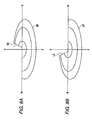
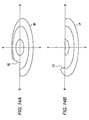
- FIGS. 4A to 4C show a high-beam light distribution pattern formed on a virtual vertical screen located at a predetermined position in front of the lighting device, for example, at a position of 25 m ahead of the lighting device.
- FIG. 4A shows a right side light distribution pattern RP formed by the right side lighting device 30R.
- the right side light distribution pattern RP has an elliptical shape in its entirety. Further, the distribution pattern is symmetrical with respect to the line V-V serving as the vertical line that passes the vanishing point in the front direction of the vehicle headlamp 10. Furthermore, the region above the line H-H is slightly smaller than the region below the line H-H.
- the three ellipses in the figure express differences in the illuminance. A part closer to the center has a higher illuminance.
- Each inclined line in the figure indicates the cutoff line RC formed in the right side light distribution pattern RP.
- the projection lens 22 composed of a planar-convex aspheric lens is arranged in front of the high-beam formation shade 26.
- the projection image formed in the high-beam illumination area is inverted on the virtual vertical screen.
- the cutoff line RC is movable horizontally in a direction of crossing the optical axis Ax.
- the cutoff line RC is a straight line extending toward the upper right, and is located on the right side of the line V-V in the initial state.
- the moving range of the cutoff line RC is determined by the movable region of the high-beam formation shade 26.
- the cutoff line RC is movable to both sides of the line V-V, only by approximately 1/2 of the ellipse major axis. However, it is preferable that the cutoff line RC is movable over an almost entire range of the major axis.
- FIG. 4B shows a left side light distribution pattern LP formed by the left side lighting device 30L.
- the left side light distribution pattern LP has an elliptical shape in its entirety. Further, the shape is symmetrical with respect to the line V-V, while the region above the line H-H is slightly smaller than the region below the line H-H.
- the cutoff line LC is a straight line extending toward the lower right, and is located on the left side of the line V-V in the initial state. The other points in the configuration are similar to those of the cutoff line RC.
- the inclination angles of the cutoff lines RC and LC are approximately 60 degrees relative to the line H-H. This angle value has been determined empirically with taking into consideration: the influence to the driver of an in-front vehicle caused at the time of projection of an overall light distribution pattern described later; the illuminance of the road surface at that time; and the like. However, depending on the characteristics or the like of the headlamp, the inclination angles of the cutoff lines may be greater or smaller than 60 degrees.
- FIG. 4C shows an overall light distribution pattern generated by superposing the right side light distribution pattern RP and the left side light distribution pattern LP.
- Each of the right side light distribution pattern RP and the left side light distribution pattern LP generates an ellipse of the same size.
- the part below the line H-H has twice the illuminance in comparison with a single pattern.
- a part of the pattern has twice the illuminance.
- a V-shaped shaded region is formed in the part above the line H-H of the overall light distribution pattern.
- the V-shaped shaded region can be moved horizontally along the maj or axis of the ellipse.
- the shaded region can be moved vertically in the part above the line H-H. This situation is described later in detail with reference to FIG. 7 and the subsequent figures.
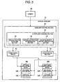
- FIG. 5 is a functional block diagram showing an overall configuration of the vehicle headlamp 10.
- each block shown here may be implemented by electric elements such as a CPU and a memory of a computer as well as by a mechanical devices, an electric circuit, or the like.
- each block may be implemented by a computer program or the like.
- each block is in the form of a functional block implemented by the cooperation of these components.
- these functional blocks may be implemented in various forms obtained by combining hardware and software.
- the headlight device control section 40 controls the ON/OFF of the left side lighting device 30L and the right side lighting device 30R and the operation of the shades provided in the lighting devices.
- the headlight device control section 40 issues an instruction to the power supply circuit 42 so as to turn ON or OFF the left side lighting device 30L and the right side lighting device 30R.
- the headlight device control section 40 instructs the shade driving section 44 such as to move the low-beam formation shade 24 into the upright position.
- the shade driving section 44 activates the low-shade drive motors 34L and 34R. As a result, a low-beam light distribution pattern is projected.
- the headlight device control section 40 instructs the shade driving section 44 such as to tilt the low-beam formation shade 24.
- the shade driving section 44 activates the low-shade drive motors 34L and 34R.
- the low-beam formation shade 24 is tilted down in a forward direction, and hence a high-beam light distribution pattern is projected.
- the cutoff line changing section 50 has a vehicle position detecting section 52, a cutoff line position determination section 54, and a shade movement amount instruction section 56.
- the vehicle position detecting section 52 detects the position occupied by an in-front vehicle within the light distribution pattern. Specifically, within the image of the vehicle front acquired by the camera 90, the vehicle position detecting section 52 detects the parts corresponding to the headlights or tail lights of the vehicle in accordance with a known algorithm, and then determines the vehicle position with reference to the line H-H and the line V-V in the light distribution pattern. The vehicle position data is outputted to the cutoff line position determination section 54. Techniques of detecting an in-front vehicle from such an image acquired by a camera are common knowledge. Thus, detailed description is omitted here. In place of the camera 90, another detecting means such as a millimeter wave radar and an infrared ray radar may be employed for detecting the position of an in-front vehicle.
- a millimeter wave radar and an infrared ray radar may be employed for detecting the position of an in-front vehicle.
- the cutoff line position determination section 54 determines the horizontal positions of the cutoff lines RC and LC in the right side light distribution pattern RP and the left side light distribution pattern LP such that a shaded region should be formed in accordance with the vehicle position detected by the vehicle position detecting section 52. That is, the cutoff line positions are determined such that an appropriate shaded region that does not cause glare to the in-front vehicle should be formed within the overall light distribution pattern obtained by combining the right side light distribution pattern RP and left side light distribution pattern LP. It is preferable that the cutoff lines are arranged such that the intersecting points between the cutoff lines and the line H-H should be located slightly on the outer sides relative to the two ends of the detected in-front vehicle.
- the shade movement amount instruction section 56 calculates the amounts of movement for the high-beam formation shades 26 in the right side lighting device 30R and the left side lighting device 30L such that the cutoff lines RC and LC of the right side light distribution pattern RP and the left side light distribution pattern LP should be located at the horizontal positions having been set up by the cutoff line position determination section 54. Then, the shade movement amount instruction section 56 issues an instruction to the shade driving section 44. The shade driving section 44 transmits a driving signal to the high-shade drive motors 32L and 32R such that the amount of movement instructed by the shade movement amount instruction section 56 should be realized.
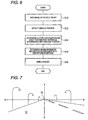
- FIG. 6 is a flow chart showing a flow of shading control performed in accordance with the vehicle position according to the present embodiment.
- the camera 90 mounted on the vehicle takes an image of the vehicle front (S10).
- the vehicle position detecting section 52 detects the position occupied by an in-front vehicle within the high-beam light distribution pattern (S12).
- the cutoff line position determination section 54 determines the cutoff line positions in the right side light distribution pattern RP and the left side light distribution pattern LP such that an overall light distribution pattern should be formed in which a shaded region is located at the vehicle part (S14).
- the shade movement amount instruction section 56 determines the amounts of movement for the high-beam formation shades 26 in the left side lighting device 30L and the right side lighting device 30R (S16).
- the shade driving section 44 transmits a control signal corresponding to the shade movement amount to the high-shade drive motors 32R and 32L (S18).
- the operation in the above-mentioned configuration according to the present embodiment is as follows.
- the high-beam formation shades are moved within the left and the right lighting devices such as to form a right side light distribution pattern in which a cutoff line is located at the right-hand end of the vehicle position and a left side light distribution pattern in which a cutoff line is located at the left-hand end of the vehicle position.
- the overall light distribution pattern generated by superposing the left and the right light distribution patterns formed as described above is projected so that a light distribution is realized that does not cause glare to the driver of the in-front vehicle.
- FIG. 7 shows a situation that an in-front vehicle 70 is observed during the time that the own vehicle runs on a straight road 72.
- FIG. 8A shows a right side light distribution pattern RP formed by the right side lighting device 30R at the time that an image of the vehicle front is taken in the situation shown in FIG. 7 .
- the position of the cutoff line RC extending toward the upper right is determined such that the intersecting point with the line H-H should be located at the right-hand end of the in-front vehicle 70.
- FIG. 8B shows a left side light distribution pattern LP formed similarly by the left side lighting device 30L.
- the position of the cutoff line LC extending toward the lower right is determined such that the contact point with the line H-H should be located at the left-hand end of the in-front vehicle 70.
- FIG. 9 shows a situation that an overall light distribution pattern generated by superposing the right side light distribution pattern RP and the left side light distribution pattern LP shown in FIG. 8 is projected.
- a valley-shaped shaded region formed by the cutoff lines RC and LC in accordance with the position of the in-front vehicle 70 is generated in the overall light distribution pattern.
- FIG. 10 shows a situation that an in-front vehicle 70 is observed when the own vehicle runs on an ascending slope road 74 that has an ascending slope in front.
- FIG. 11A shows a right side light distribution pattern RP formed by the right side lighting device 30R at the time that an image of the vehicle front is taken in the situation shown in FIG. 10 .
- FIG. 11B shows a left side light distribution pattern LP formed similarly by the left side lighting device 30L. In this case, the in-front vehicle 70 is located above the line H-H.
- the cutoff line position determination section 54 determines the horizontal positions of the cutoff lines RC and LC such that the intersecting point 75 of the cutoff lines RC and LC should be located slightly below the lower end of the detected in-front vehicle.
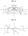
- FIG. 12 shows a situation that an overall light distribution pattern generated by superposing the right side light distribution pattern RP and the left side light distribution pattern LP shown in FIG. 11 is projected.
- the intersecting point 75 of the cutoff lines RC and LC is located below the in-front vehicle 70.
- a V-shaped shaded region is formed in the overall light distribution pattern.
- the intersecting point 75 can be moved up or down in accordance with the vehicle position.
- FIG. 10 shows a situation that the in-front vehicle 70 is located on the line V-V.
- both of the cutoff lines RC and LC are moved leftward or rightward, the shaded region can be moved such as to follow the vertical movement of the vehicle.
- FIG. 13 shows a situation that an in-front vehicle 70 is observed during the time that the own vehicle runs on a curved road 76.
- the in-front vehicle 70 is located at a left position distant from the line V-V. Even in such a case, the shaded region can be moved in accordance with the vehicle position.
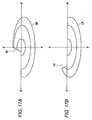
- FIG. 14A shows a right side light distribution pattern RP formed by the right side lighting device 30R at the time that an image of the vehicle front is taken in the situation shown in FIG. 13 .
- FIG. 14B shows a left side light distribution pattern LP formed similarly by the left side lighting device 30L.
- the cutoff line position determination section 54 arranges the intersecting point of the cutoff line RC and the line H-H at the right-hand end of the in-front vehicle, and arranges the intersecting point of the cutoff line LC and the line H-H at the left-hand end of the in-front vehicle.
- the cutoff line RC is located on the left side greatly exceeding the line V-V.
- the right side light distribution pattern RP has an illumination area having approximately an elliptical shape.
- the cutoff line LC is located near the left-hand end of the ellipse.
- the illumination area of the left side light distribution pattern LP is almost the lower half of the ellipse.
- FIG. 15 shows a situation that an overall light distribution pattern generated by superposing the right side light distribution pattern RP and the left side light distribution pattern LP shown in FIG. 14 is projected. As illustrated, even when the horizontal position of the in-front vehicle deviates to the left, the overall light distribution pattern can be formed that has a shaded region minimized in accordance with the vehicle position.
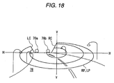
- FIG. 16 shows a situation that an ahead-going vehicle 70a and an oncoming vehicle 70b are observed during the time that the own vehicle runs on a curved road 78.
- FIG. 17A shows a right side light distribution pattern RP formed by the right side lighting device 30R at the time that an image of the vehicle front is taken in the situation shown in FIG. 16 .
- FIG. 17B shows a left side light distribution pattern LP formed similarly by the left side lighting device 30L.
- the cutoff line position determination section 54 arranges the intersecting point between the cutoff line RC and the line H-H at the right-hand end of the rightmost vehicle, and arranges the intersecting point between the cutoff line LC and the line H-H at the left-hand end of the leftmost vehicle.
- FIG. 18 shows a situation that an overall light distribution pattern generated by superposing the right side light distribution pattern RP and the left side light distribution pattern LP shown in FIG. 17 is projected.
- the shaded region has a slightly horizontally elongated trapezoidal shape.
- a light distribution pattern having a minimized shaded region can illuminate the road surface.
- the cutoff line position can be moved horizontally within each light distribution pattern.
- the shaded region can be moved arbitrarily in a horizontal direction.
- an overall light distribution pattern can be generated that has a shaded region only at the in-front vehicle position.
- the cutoff line positions can also be moved continuously within the light distribution pattern.
- the range of the shaded region can be set up optimally.
- a satisfactory illuminance of the road surface can be ensured in a state that the shaded range is minimized.
- the cutoff lines are formed non-perpendicular. That is, one cutoff line is composed of a straight line extending toward the upper right, while the other cutoff line is composed of a straight line extending the lower right.
- a light distribution pattern can be formed whose illumination area extends rightward and leftward from the in-front vehicle.
- a slightly distant place is illuminated. This reduces the occasion that the driver of the in-front vehicle feels intimidation of being illuminated immediately from the behind.
- the shaded region in the overall light distribution pattern can be formed in a V-shape.
- the V-shaped shaded region can be moved in the vertical direction.
- the position of the shaded region can be changed such as to follow the positional fluctuation of the in-front vehicle in the up and down directions.
- the shaded range can be minimized.
- the approach that cutoff lines are moved within a high-beam light distribution pattern so that a shaded region is formed like in the present embodiment has also the following advantages. That is, in the prior art, when the mode is changed from a high beam to a low beam in order to avoid glare to the in-front vehicle, the side areas of the in-front vehicle cannot be illuminated, and hence forward visibility is degraded. In contrast, according to the present embodiment, forward visibility is hardly degraded. Further, in the prior art, when the lighting device is swiveled such that the in-front vehicle should not be illuminated, the shaded region would unnecessarily be expanded or alternatively an unnecessary wide area on each side of the road would be illuminated.
- the first embodiment has been described for a case that a high-beam formation shade 26 provided in each of the left and the right lighting devices is driven so that the cutoff line position in the light distribution pattern formed by each lighting device is moved.
- the high-beam formation shades 27 are fixed, whereas the left and the right lighting devices are swiveled so that the direction of the optical axes is changed. By virtue of this, the cutoff line position is moved in the light distribution pattern formed by each lighting device.
- FIG. 19 is a schematic vertical cross sectional view of a vehicle headlamp 80 according to the second embodiment.
- FIG. 19 shows the left side lighting device 30L.
- the right side lighting device has a similar configuration except that the shape of the high-beam formation shade is in right-left symmetry to the left one.
- the vehicle headlamp 80 according to the second embodiment is different from that of the first embodiment in the point that a swiveling motor 33L is provided for changing the angle of the optical axis Ax of the left side lighting device 30L in response to an instruction from an optical axis adjustment section 46.
- the lighting device 30L is supported by the lamp body 12 in a swing-permitted manner at least in the right and left directions.
- the swiveling motor 33L is attached to the lower base part of the holder 36, and supports the entire lighting device in a rotatable manner around the shaft 47.
- the other points in the configuration of the vehicle headlamp 80 are similar to those of the first embodiment, and hence their description is omitted.
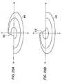
- FIGS. 20A and 20B show high-beam light distribution patterns formed on a virtual vertical screen by the vehicle headlamp 80.
- FIG. 20A shows a right side light distribution pattern RP2 formed by the right side lighting device 30R
- FIG. 20B shows a left side light distribution pattern LP2 formed by the left side lighting device 30L.
- the cutoff lines RC2 and LC2 in the individual light distribution patterns are fixed. That is, their positions are not changed.
- the cutoff line RC2 is a straight line extending toward the upper right, and is arranged such that the upper end should be located on the line V-V.
- the cutoff line LC2 is a straight line extending toward the lower right, and is arranged such that the upper end should be located on the line V-V.
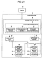
- FIG. 21 is a functional block diagram showing the configuration of the vehicle headlamp according to the second embodiment. Also in this figure, each component is implemented by hardware, software, or a combination of these.
- the cutoff line changing section 50 has a vehicle position detecting section 52, a cutoff line position determination section 54, and an optical axis changing instruction section 57.
- the vehicle position detecting section 52 detects the position occupied by an in-front vehicle within the light distribution pattern.
- the cutoff line position determination section 54 determines the horizontal positions of the cutoff lines RC2 and LC2 in the right side light distribution pattern RP2 and the left side light distribution pattern LP2 such that a shaded region should be formed in accordance with the vehicle position detected by the vehicle position detecting section 52. It is preferable that the horizontal positions are set up such that the intersecting points between the cutoff lines and the line H-H should be located slightly on the outer sides relative to the two ends of the detected in-front vehicle.
- the optical axis changing instruction section 57 calculates the angle of the optical axes Ax of the right side lighting device 30R and the left side lighting device 30L such that the cutoff line RC2 of the right side light distribution pattern RP2 and the cutoff line LC2 of the left side light distribution pattern LP2 should be located at the positions determined by the cutoff line position determination section 54, and then issues an instruction to the optical axis adjustment section 46.
- the optical axis adjustment section 46 transmits a control signal to the swiveling motors 33L and 33R of the left and the right lighting devices such that the optical axial angle instructed by the optical axis changing instruction section 57 should be realized. As a result, the right and left directional angle of the optical axis Ax of the left and the right lighting devices is adjusted.
- the operation in the above-mentioned configuration according to the present embodiment is as follows.
- the right side lighting device is swiveled such that the cutoff line of the right side light distribution pattern should be located at the right-hand end of the vehicle position within the light distribution pattern.
- the left side lighting device is swiveled such that the cutoff line of the left side light distribution pattern should be located at the left-hand end of the vehicle position.
- the overall light distribution pattern generated by superposing the left and the right light distribution patterns formed as described above is projected so that a light distribution is realized that does not cause glare to the driver of the in-front vehicle.
- FIG. 22 shows an overall light distribution pattern used in a case that an in-front vehicle 70 is observed in front of the own vehicle that runs on a straight road 72.
- the configuration that the cutoff line RC2 of the right side light distribution pattern RP2 is located at the right-hand end of the in-front vehicle 70 and that the cutoff line LC2 of the left side light distribution pattern LP2 is located at the left-hand end of the in-front vehicle 70 is similar to that of the first embodiment (see FIG. 7 ).
- the cutoff line position within each light distribution pattern is fixed.
- the optical axes of the left and the right lighting devices are tilted. Accordingly, the right side light distribution pattern RP2 and the left side light distribution pattern LP2 do not completely overlap with each other, and hence are projected in a shape expanded in the right and left directions.
- FIG. 23 shows an overall light distribution pattern used in a case that an in-front vehicle 70 is observed in front of the own vehicle that runs on an ascending slope road 74.
- the point that the lower end of the intersecting point 77 of the cutoff line RC2 and the cutoff line LC2 should be arranged in accordance with the vertical directional position of the in-front vehicle 70 is similar to that of the first embodiment (see FIG. 10 ).
- the right side light distribution pattern RP2 and the left side light distribution pattern LP2 do not completely overlap with each other.
- the optical axes of the left and the right lighting devices have smaller tilting angles.
- the illumination area of the road is slightly small on the two sides.
- FIG. 24 shows an overall light distribution pattern used in a case that an in-front vehicle 70 is observed in front of the own vehicle that runs on a curved road 76.
- the configuration that the cutoff line RC2 of the right side light distribution pattern RP2 is located at the right-hand end of the in-front vehicle 70 and that the cutoff line LC2 of the left side light distribution pattern LP2 is located at the left-hand end of the in-front vehicle 70 is similar to that of the first embodiment (see FIG. 13 ).
- the illumination area is expanded in the right and left directions, in particular, toward the left side of the road.
- the angle of the optical axis of each lighting device is changed in the right and left directions so that the cutoff line positions are moved horizontally within the right side light distribution pattern and the left side light distribution pattern.
- the shaded region can be moved arbitrarily in a horizontal direction.
- an overall light distribution pattern can be generated that has a shaded region only at the in-front vehicle position.
- the cutoff line positions can also be moved continuously within the light distribution pattern.
- the range of the shaded region can be set up optimally.
- a satisfactory illuminance of the road surface can be ensured in a state that the shaded range is minimized.
- the present invention is not limited to the above specific embodiments. That is, modifications such as various kinds of design change may be performed on the basis of knowledge owned by a person skilled in the art.
- the configuration shown in each figure is an illustrative example, and hence may be modified appropriately as long as a similar function is achievable.
- the lighting device 30 in each embodiment is of a direct projection type in which light from the bulb 86 is directly projected by the projection lens 22.
- the lighting device 30 may be of a so-called reflection type.
- the cutoff lines formed in the right side light distribution pattern and the left side light distribution pattern may be curved lines in place of the straight lines.
- the shaded region formed in the overall light distribution pattern can be of a U-shape in place of a V-shape.
- the embodiments have been described for a case that the right side lighting device forms a right side light distribution pattern while the left side lighting device forms a left side light distribution pattern. However, this relation may be reversed. That is, the right side lighting device may form a left side light distribution pattern while the left side lighting device may form a right side light distribution pattern.
- the embodiments have been described for a case that the right side lighting device and the left side lighting device are those switchable between a low beam and a high beam.
- these lighting devices may be high-beam dedicated devices. That is, a high-beam formation shade may solely be provided in each lighting device.
- the first embodiment has been described for a case that the high-beam formation shade is driven in a direction of crossing the optical axis so that the cutoff line is moved within the light distribution pattern.
- a so-called rotary shade may be provided in which a plurality of high-beam formation shades having mutually different shading areas are attached to the circumference side-surfaces of a revolving shaft with intervals with each other. Then, the shaft is revolved so that any one of the shades is located at the focal point of the reflector. By virtue of this, the cutoff line is moved within the light distribution pattern.
- the lighting device having a configuration that the high-beam formation shade is movable according to the first embodiment may be used in combination with a well-known swivel mechanism.
Applications Claiming Priority (1)
| Application Number | Priority Date | Filing Date | Title |
|---|---|---|---|
| JP2008074438A JP2009231020A (ja) | 2008-03-21 | 2008-03-21 | 車両用前照灯装置 |
Publications (3)
| Publication Number | Publication Date |
|---|---|
| EP2103868A2 true EP2103868A2 (de) | 2009-09-23 |
| EP2103868A3 EP2103868A3 (de) | 2010-10-06 |
| EP2103868B1 EP2103868B1 (de) | 2012-01-18 |
Family
ID=40750909
Family Applications (1)
| Application Number | Title | Priority Date | Filing Date |
|---|---|---|---|
| EP09004044A Expired - Fee Related EP2103868B1 (de) | 2008-03-21 | 2009-03-20 | Fahrzeugscheinwerfer |
Country Status (2)
| Country | Link |
|---|---|
| EP (1) | EP2103868B1 (de) |
| JP (1) | JP2009231020A (de) |
Cited By (12)
| Publication number | Priority date | Publication date | Assignee | Title |
|---|---|---|---|---|
| EP2295291A1 (de) * | 2009-09-15 | 2011-03-16 | Koito Manufacturing Co., Ltd. | Fahrzeug-Scheinwerfervorrichtung |
| WO2011060860A1 (de) * | 2009-11-21 | 2011-05-26 | Volkswagen Aktiengesellschaft | Verfahren zum steuern einer scheinwerferanordnung für ein fahrzeug und scheinwerferanordnung |
| EP2279908A3 (de) * | 2009-07-29 | 2011-07-20 | Koito Manufacturing Co., Ltd. | Fahrzeugschweinwerfervorrichtung mit Schwenkfunktion der Lampeneinheit |
| CN102951064A (zh) * | 2011-08-11 | 2013-03-06 | 株式会社小糸制作所 | 车辆用前照灯装置及配光控制方法 |
| CN103244885A (zh) * | 2012-02-02 | 2013-08-14 | 市光工业株式会社 | 车辆用前照灯以及车辆用前照灯装置 |
| EP2666671A1 (de) * | 2012-05-23 | 2013-11-27 | SL Corporation | Fahrzeugscheinwerfersystem und Verfahren zu dessen Steuerung |
| CN104806945A (zh) * | 2014-03-03 | 2015-07-29 | 尤国锋 | 汽车前照灯 |
| EP2644449A4 (de) * | 2010-11-24 | 2015-08-05 | Toyota Motor Co Ltd | Beleuchtungsvorrichtung für ein fahrzeug und steuerverfahren für fahrzeugscheinwerfer |
| US9260053B2 (en) | 2011-05-23 | 2016-02-16 | Sl Corporation | Automotive headlamp system and method of controlling the same |
| EP3018007A3 (de) * | 2014-11-06 | 2016-11-16 | Volkswagen Aktiengesellschaft | Verfahren zum steuern einer scheinwerferanordnung für ein fahrzeug und scheinwerferanordnung |
| CN114368340A (zh) * | 2022-02-14 | 2022-04-19 | 太原理工大学 | 一种车辆远光灯智能调节装置和方法 |
| US20230137589A1 (en) * | 2020-04-17 | 2023-05-04 | Hasco Vision Technology Co., Ltd. | Primary optical structure, high-beam lighting device, anti-glare high-beam lamp and vehicle |
Families Citing this family (8)
| Publication number | Priority date | Publication date | Assignee | Title |
|---|---|---|---|---|
| JP2011090839A (ja) * | 2009-10-21 | 2011-05-06 | Koito Mfg Co Ltd | 車両用前照灯 |
| JP5410259B2 (ja) * | 2009-12-10 | 2014-02-05 | 株式会社小糸製作所 | 車両用照明灯具 |
| JP5562751B2 (ja) * | 2010-07-26 | 2014-07-30 | 株式会社小糸製作所 | 車両用照明灯具 |
| JP2012190556A (ja) * | 2011-03-08 | 2012-10-04 | Koito Mfg Co Ltd | 車両用照明灯具 |
| JP5828424B2 (ja) * | 2011-10-28 | 2015-12-09 | 株式会社小糸製作所 | 車輌用前照灯 |
| JP6051533B2 (ja) * | 2012-02-02 | 2016-12-27 | 市光工業株式会社 | 車両用前照灯および車両用前照灯装置 |
| JP5866242B2 (ja) * | 2012-04-02 | 2016-02-17 | 株式会社小糸製作所 | 車両用灯具装置 |
| JP6539112B2 (ja) * | 2015-05-22 | 2019-07-03 | 株式会社小糸製作所 | 車両用灯具ユニットおよび回転遮光部材 |
Citations (4)
| Publication number | Priority date | Publication date | Assignee | Title |
|---|---|---|---|---|
| DE19501173A1 (de) * | 1995-01-17 | 1996-07-18 | Bosch Gmbh Robert | Scheinwerfer für Fahrzeuge |
| DE10248445A1 (de) * | 2001-10-17 | 2003-05-15 | Koito Mfg Co Ltd | Fahrzeugscheinwerfer |
| DE102004025433A1 (de) * | 2003-05-22 | 2004-12-23 | Koito Mfg. Co., Ltd. | Fahrzeugscheinwerfer |
| WO2009039882A1 (de) * | 2007-09-24 | 2009-04-02 | Hella Kgaa Hueck & Co. | Projektionsscheinwerferanordnung für fahrzeuge |
-
2008
- 2008-03-21 JP JP2008074438A patent/JP2009231020A/ja active Pending
-
2009
- 2009-03-20 EP EP09004044A patent/EP2103868B1/de not_active Expired - Fee Related
Patent Citations (4)
| Publication number | Priority date | Publication date | Assignee | Title |
|---|---|---|---|---|
| DE19501173A1 (de) * | 1995-01-17 | 1996-07-18 | Bosch Gmbh Robert | Scheinwerfer für Fahrzeuge |
| DE10248445A1 (de) * | 2001-10-17 | 2003-05-15 | Koito Mfg Co Ltd | Fahrzeugscheinwerfer |
| DE102004025433A1 (de) * | 2003-05-22 | 2004-12-23 | Koito Mfg. Co., Ltd. | Fahrzeugscheinwerfer |
| WO2009039882A1 (de) * | 2007-09-24 | 2009-04-02 | Hella Kgaa Hueck & Co. | Projektionsscheinwerferanordnung für fahrzeuge |
Cited By (18)
| Publication number | Priority date | Publication date | Assignee | Title |
|---|---|---|---|---|
| EP2279908A3 (de) * | 2009-07-29 | 2011-07-20 | Koito Manufacturing Co., Ltd. | Fahrzeugschweinwerfervorrichtung mit Schwenkfunktion der Lampeneinheit |
| US9956901B2 (en) | 2009-07-29 | 2018-05-01 | Koito Manufacturing Co., Ltd. | Automotive headlamp apparatus having swivel function of lamp unit |
| EP2295291A1 (de) * | 2009-09-15 | 2011-03-16 | Koito Manufacturing Co., Ltd. | Fahrzeug-Scheinwerfervorrichtung |
| WO2011060860A1 (de) * | 2009-11-21 | 2011-05-26 | Volkswagen Aktiengesellschaft | Verfahren zum steuern einer scheinwerferanordnung für ein fahrzeug und scheinwerferanordnung |
| CN102712283A (zh) * | 2009-11-21 | 2012-10-03 | 大众汽车有限公司 | 用于控制车辆的前照灯装置的方法和前照灯装置 |
| US8862336B2 (en) | 2009-11-21 | 2014-10-14 | Volkswagen Ag | Method for controlling a headlamp system for a vehicle, and headlamp system |
| CN102712283B (zh) * | 2009-11-21 | 2015-09-16 | 大众汽车有限公司 | 用于控制车辆的前照灯装置的方法和前照灯装置 |
| EP2644449A4 (de) * | 2010-11-24 | 2015-08-05 | Toyota Motor Co Ltd | Beleuchtungsvorrichtung für ein fahrzeug und steuerverfahren für fahrzeugscheinwerfer |
| US9260053B2 (en) | 2011-05-23 | 2016-02-16 | Sl Corporation | Automotive headlamp system and method of controlling the same |
| CN102951064A (zh) * | 2011-08-11 | 2013-03-06 | 株式会社小糸制作所 | 车辆用前照灯装置及配光控制方法 |
| CN102951064B (zh) * | 2011-08-11 | 2015-08-05 | 株式会社小糸制作所 | 车辆用前照灯装置及配光控制方法 |
| CN103244885A (zh) * | 2012-02-02 | 2013-08-14 | 市光工业株式会社 | 车辆用前照灯以及车辆用前照灯装置 |
| EP2666671A1 (de) * | 2012-05-23 | 2013-11-27 | SL Corporation | Fahrzeugscheinwerfersystem und Verfahren zu dessen Steuerung |
| CN104806945A (zh) * | 2014-03-03 | 2015-07-29 | 尤国锋 | 汽车前照灯 |
| EP3018007A3 (de) * | 2014-11-06 | 2016-11-16 | Volkswagen Aktiengesellschaft | Verfahren zum steuern einer scheinwerferanordnung für ein fahrzeug und scheinwerferanordnung |
| US20230137589A1 (en) * | 2020-04-17 | 2023-05-04 | Hasco Vision Technology Co., Ltd. | Primary optical structure, high-beam lighting device, anti-glare high-beam lamp and vehicle |
| CN114368340A (zh) * | 2022-02-14 | 2022-04-19 | 太原理工大学 | 一种车辆远光灯智能调节装置和方法 |
| CN114368340B (zh) * | 2022-02-14 | 2023-11-28 | 太原理工大学 | 一种车辆远光灯智能调节装置和方法 |
Also Published As
| Publication number | Publication date |
|---|---|
| JP2009231020A (ja) | 2009-10-08 |
| EP2103868B1 (de) | 2012-01-18 |
| EP2103868A3 (de) | 2010-10-06 |
Similar Documents
| Publication | Publication Date | Title |
|---|---|---|
| EP2103868B1 (de) | Fahrzeugscheinwerfer | |
| JP5260098B2 (ja) | 車両用前照灯装置 | |
| CN102109137B (zh) | 车辆用前照灯装置 | |
| US8552648B2 (en) | Vehicle headlamp apparatus | |
| US8979334B2 (en) | Automotive headlamp apparatus and light distribution control method | |
| JP5074888B2 (ja) | 車両用ランプシステム | |
| JP4873584B2 (ja) | 種々異なる特性を有する光束を生ぜしめるための、車両用の前照灯装置 | |
| JP2009179113A (ja) | 車両用前照灯装置およびその制御方法 | |
| EP2374660B1 (de) | Steuervorrichtung, fahrzeuglampensystem und fahrzeuglampe | |
| JP7155124B2 (ja) | 灯具ユニットおよび車両用前照灯 | |
| US20060023465A1 (en) | Vehicle headlamp | |
| JP2004327187A (ja) | 車両用前照灯 | |
| EP2100771B1 (de) | Fahrzeugscheinwerfervorrichtung und Verfahren zu deren Steuerung | |
| JP5430282B2 (ja) | 車両用前照灯の配光制御システム | |
| JP5132535B2 (ja) | 車両用前照灯 | |
| JP2010235108A (ja) | 車両用前照灯装置 | |
| US7021791B1 (en) | Vehicular headlamp apparatus | |
| JP2012162105A (ja) | 車両用前照灯装置 | |
| JP5539796B2 (ja) | 車両用前照灯システム | |
| EP2388164A2 (de) | Fahrzeugscheinwerfersystem, Steuervorrichtung, Fahrzeugscheinwerfer und Steuerverfahren des Fahrzeugscheinwerfers | |
| JP5611406B2 (ja) | 車両用前照灯装置 | |
| EP2384933B1 (de) | Fahrzeugscheinwerfersystem, Steuerungsvorrichtung und Fahrzeugscheinwerfer | |
| JPH0533402U (ja) | 投射型自動車用ヘツドランプ | |
| JP2010015837A (ja) | 車両用前照灯装置 | |
| JP4261448B2 (ja) | 車両用前照灯 |
Legal Events
| Date | Code | Title | Description |
|---|---|---|---|
| PUAI | Public reference made under article 153(3) epc to a published international application that has entered the european phase |
Free format text: ORIGINAL CODE: 0009012 |
|
| 17P | Request for examination filed |
Effective date: 20090320 |
|
| AK | Designated contracting states |
Kind code of ref document: A2 Designated state(s): AT BE BG CH CY CZ DE DK EE ES FI FR GB GR HR HU IE IS IT LI LT LU LV MC MK MT NL NO PL PT RO SE SI SK TR |
|
| AX | Request for extension of the european patent |
Extension state: AL BA RS |
|
| PUAL | Search report despatched |
Free format text: ORIGINAL CODE: 0009013 |
|
| AK | Designated contracting states |
Kind code of ref document: A3 Designated state(s): AT BE BG CH CY CZ DE DK EE ES FI FR GB GR HR HU IE IS IT LI LT LU LV MC MK MT NL NO PL PT RO SE SI SK TR |
|
| AX | Request for extension of the european patent |
Extension state: AL BA RS |
|
| AKX | Designation fees paid |
Designated state(s): DE FR GB |
|
| GRAP | Despatch of communication of intention to grant a patent |
Free format text: ORIGINAL CODE: EPIDOSNIGR1 |
|
| RIC1 | Information provided on ipc code assigned before grant |
Ipc: F21W 101/10 20060101ALN20110609BHEP Ipc: F21V 14/08 20060101ALI20110609BHEP Ipc: F21S 8/12 20060101AFI20110609BHEP |
|
| RIN1 | Information on inventor provided before grant (corrected) |
Inventor name: YAMAMURA, SATOSHIC/O KOITO MANUFACTURING CO., LTD. |
|
| GRAS | Grant fee paid |
Free format text: ORIGINAL CODE: EPIDOSNIGR3 |
|
| GRAA | (expected) grant |
Free format text: ORIGINAL CODE: 0009210 |
|
| AK | Designated contracting states |
Kind code of ref document: B1 Designated state(s): DE FR GB |
|
| REG | Reference to a national code |
Ref country code: GB Ref legal event code: FG4D |
|
| REG | Reference to a national code |
Ref country code: DE Ref legal event code: R096 Ref document number: 602009004640 Country of ref document: DE Effective date: 20120315 |
|
| PGFP | Annual fee paid to national office [announced via postgrant information from national office to epo] |
Ref country code: FR Payment date: 20120214 Year of fee payment: 4 |
|
| PGFP | Annual fee paid to national office [announced via postgrant information from national office to epo] |
Ref country code: DE Payment date: 20120328 Year of fee payment: 4 |
|
| PLBE | No opposition filed within time limit |
Free format text: ORIGINAL CODE: 0009261 |
|
| STAA | Information on the status of an ep patent application or granted ep patent |
Free format text: STATUS: NO OPPOSITION FILED WITHIN TIME LIMIT |
|
| 26N | No opposition filed |
Effective date: 20121019 |
|
| REG | Reference to a national code |
Ref country code: DE Ref legal event code: R097 Ref document number: 602009004640 Country of ref document: DE Effective date: 20121019 |
|
| GBPC | Gb: european patent ceased through non-payment of renewal fee |
Effective date: 20130320 |
|
| REG | Reference to a national code |
Ref country code: FR Ref legal event code: ST Effective date: 20131129 |
|
| REG | Reference to a national code |
Ref country code: DE Ref legal event code: R119 Ref document number: 602009004640 Country of ref document: DE Effective date: 20131001 |
|
| PG25 | Lapsed in a contracting state [announced via postgrant information from national office to epo] |
Ref country code: GB Free format text: LAPSE BECAUSE OF NON-PAYMENT OF DUE FEES Effective date: 20130320 Ref country code: DE Free format text: LAPSE BECAUSE OF NON-PAYMENT OF DUE FEES Effective date: 20131001 Ref country code: FR Free format text: LAPSE BECAUSE OF NON-PAYMENT OF DUE FEES Effective date: 20130402 |