EP2103847A2 - Steuereinrichtung für stufenlos verstellbares Getriebe und Steuerungsverfahren hierfür - Google Patents
Steuereinrichtung für stufenlos verstellbares Getriebe und Steuerungsverfahren hierfür Download PDFInfo
- Publication number
- EP2103847A2 EP2103847A2 EP08022041A EP08022041A EP2103847A2 EP 2103847 A2 EP2103847 A2 EP 2103847A2 EP 08022041 A EP08022041 A EP 08022041A EP 08022041 A EP08022041 A EP 08022041A EP 2103847 A2 EP2103847 A2 EP 2103847A2
- Authority
- EP
- European Patent Office
- Prior art keywords
- oil pressure
- correction amount
- clutch
- pulse
- travel position
- Prior art date
- Legal status (The legal status is an assumption and is not a legal conclusion. Google has not performed a legal analysis and makes no representation as to the accuracy of the status listed.)
- Withdrawn
Links
Images




Classifications
-
- F—MECHANICAL ENGINEERING; LIGHTING; HEATING; WEAPONS; BLASTING
- F16—ENGINEERING ELEMENTS AND UNITS; GENERAL MEASURES FOR PRODUCING AND MAINTAINING EFFECTIVE FUNCTIONING OF MACHINES OR INSTALLATIONS; THERMAL INSULATION IN GENERAL
- F16H—GEARING
- F16H61/00—Control functions within control units of change-speed- or reversing-gearings for conveying rotary motion ; Control of exclusively fluid gearing, friction gearing, gearings with endless flexible members or other particular types of gearing
- F16H61/04—Smoothing ratio shift
- F16H61/0437—Smoothing ratio shift by using electrical signals
-
- F—MECHANICAL ENGINEERING; LIGHTING; HEATING; WEAPONS; BLASTING
- F16—ENGINEERING ELEMENTS AND UNITS; GENERAL MEASURES FOR PRODUCING AND MAINTAINING EFFECTIVE FUNCTIONING OF MACHINES OR INSTALLATIONS; THERMAL INSULATION IN GENERAL
- F16H—GEARING
- F16H61/00—Control functions within control units of change-speed- or reversing-gearings for conveying rotary motion ; Control of exclusively fluid gearing, friction gearing, gearings with endless flexible members or other particular types of gearing
- F16H61/66—Control functions within control units of change-speed- or reversing-gearings for conveying rotary motion ; Control of exclusively fluid gearing, friction gearing, gearings with endless flexible members or other particular types of gearing specially adapted for continuously variable gearings
-
- F—MECHANICAL ENGINEERING; LIGHTING; HEATING; WEAPONS; BLASTING
- F16—ENGINEERING ELEMENTS AND UNITS; GENERAL MEASURES FOR PRODUCING AND MAINTAINING EFFECTIVE FUNCTIONING OF MACHINES OR INSTALLATIONS; THERMAL INSULATION IN GENERAL
- F16D—COUPLINGS FOR TRANSMITTING ROTATION; CLUTCHES; BRAKES
- F16D48/00—External control of clutches
- F16D48/06—Control by electric or electronic means, e.g. of fluid pressure
- F16D48/066—Control of fluid pressure, e.g. using an accumulator
-
- F—MECHANICAL ENGINEERING; LIGHTING; HEATING; WEAPONS; BLASTING
- F16—ENGINEERING ELEMENTS AND UNITS; GENERAL MEASURES FOR PRODUCING AND MAINTAINING EFFECTIVE FUNCTIONING OF MACHINES OR INSTALLATIONS; THERMAL INSULATION IN GENERAL
- F16H—GEARING
- F16H59/00—Control inputs to control units of change-speed- or reversing-gearings for conveying rotary motion
- F16H59/36—Inputs being a function of speed
-
- F—MECHANICAL ENGINEERING; LIGHTING; HEATING; WEAPONS; BLASTING
- F16—ENGINEERING ELEMENTS AND UNITS; GENERAL MEASURES FOR PRODUCING AND MAINTAINING EFFECTIVE FUNCTIONING OF MACHINES OR INSTALLATIONS; THERMAL INSULATION IN GENERAL
- F16H—GEARING
- F16H61/00—Control functions within control units of change-speed- or reversing-gearings for conveying rotary motion ; Control of exclusively fluid gearing, friction gearing, gearings with endless flexible members or other particular types of gearing
- F16H61/04—Smoothing ratio shift
-
- F—MECHANICAL ENGINEERING; LIGHTING; HEATING; WEAPONS; BLASTING
- F16—ENGINEERING ELEMENTS AND UNITS; GENERAL MEASURES FOR PRODUCING AND MAINTAINING EFFECTIVE FUNCTIONING OF MACHINES OR INSTALLATIONS; THERMAL INSULATION IN GENERAL
- F16D—COUPLINGS FOR TRANSMITTING ROTATION; CLUTCHES; BRAKES
- F16D2500/00—External control of clutches by electric or electronic means
- F16D2500/10—System to be controlled
- F16D2500/102—Actuator
- F16D2500/1026—Hydraulic
-
- F—MECHANICAL ENGINEERING; LIGHTING; HEATING; WEAPONS; BLASTING
- F16—ENGINEERING ELEMENTS AND UNITS; GENERAL MEASURES FOR PRODUCING AND MAINTAINING EFFECTIVE FUNCTIONING OF MACHINES OR INSTALLATIONS; THERMAL INSULATION IN GENERAL
- F16D—COUPLINGS FOR TRANSMITTING ROTATION; CLUTCHES; BRAKES
- F16D2500/00—External control of clutches by electric or electronic means
- F16D2500/10—System to be controlled
- F16D2500/108—Gear
- F16D2500/1088—CVT
-
- F—MECHANICAL ENGINEERING; LIGHTING; HEATING; WEAPONS; BLASTING
- F16—ENGINEERING ELEMENTS AND UNITS; GENERAL MEASURES FOR PRODUCING AND MAINTAINING EFFECTIVE FUNCTIONING OF MACHINES OR INSTALLATIONS; THERMAL INSULATION IN GENERAL
- F16D—COUPLINGS FOR TRANSMITTING ROTATION; CLUTCHES; BRAKES
- F16D2500/00—External control of clutches by electric or electronic means
- F16D2500/30—Signal inputs
- F16D2500/302—Signal inputs from the actuator
- F16D2500/3024—Pressure
-
- F—MECHANICAL ENGINEERING; LIGHTING; HEATING; WEAPONS; BLASTING
- F16—ENGINEERING ELEMENTS AND UNITS; GENERAL MEASURES FOR PRODUCING AND MAINTAINING EFFECTIVE FUNCTIONING OF MACHINES OR INSTALLATIONS; THERMAL INSULATION IN GENERAL
- F16D—COUPLINGS FOR TRANSMITTING ROTATION; CLUTCHES; BRAKES
- F16D2500/00—External control of clutches by electric or electronic means
- F16D2500/30—Signal inputs
- F16D2500/314—Signal inputs from the user
- F16D2500/3146—Signal inputs from the user input from levers
- F16D2500/31466—Gear lever
-
- F—MECHANICAL ENGINEERING; LIGHTING; HEATING; WEAPONS; BLASTING
- F16—ENGINEERING ELEMENTS AND UNITS; GENERAL MEASURES FOR PRODUCING AND MAINTAINING EFFECTIVE FUNCTIONING OF MACHINES OR INSTALLATIONS; THERMAL INSULATION IN GENERAL
- F16D—COUPLINGS FOR TRANSMITTING ROTATION; CLUTCHES; BRAKES
- F16D2500/00—External control of clutches by electric or electronic means
- F16D2500/30—Signal inputs
- F16D2500/316—Other signal inputs not covered by the groups above
- F16D2500/3166—Detection of an elapsed period of time
-
- F—MECHANICAL ENGINEERING; LIGHTING; HEATING; WEAPONS; BLASTING
- F16—ENGINEERING ELEMENTS AND UNITS; GENERAL MEASURES FOR PRODUCING AND MAINTAINING EFFECTIVE FUNCTIONING OF MACHINES OR INSTALLATIONS; THERMAL INSULATION IN GENERAL
- F16D—COUPLINGS FOR TRANSMITTING ROTATION; CLUTCHES; BRAKES
- F16D2500/00—External control of clutches by electric or electronic means
- F16D2500/50—Problem to be solved by the control system
- F16D2500/502—Relating the clutch
- F16D2500/50245—Calibration or recalibration of the clutch touch-point
- F16D2500/50251—During operation
-
- F—MECHANICAL ENGINEERING; LIGHTING; HEATING; WEAPONS; BLASTING
- F16—ENGINEERING ELEMENTS AND UNITS; GENERAL MEASURES FOR PRODUCING AND MAINTAINING EFFECTIVE FUNCTIONING OF MACHINES OR INSTALLATIONS; THERMAL INSULATION IN GENERAL
- F16D—COUPLINGS FOR TRANSMITTING ROTATION; CLUTCHES; BRAKES
- F16D2500/00—External control of clutches by electric or electronic means
- F16D2500/70—Details about the implementation of the control system
- F16D2500/706—Strategy of control
- F16D2500/70605—Adaptive correction; Modifying control system parameters, e.g. gains, constants, look-up tables
-
- F—MECHANICAL ENGINEERING; LIGHTING; HEATING; WEAPONS; BLASTING
- F16—ENGINEERING ELEMENTS AND UNITS; GENERAL MEASURES FOR PRODUCING AND MAINTAINING EFFECTIVE FUNCTIONING OF MACHINES OR INSTALLATIONS; THERMAL INSULATION IN GENERAL
- F16H—GEARING
- F16H61/00—Control functions within control units of change-speed- or reversing-gearings for conveying rotary motion ; Control of exclusively fluid gearing, friction gearing, gearings with endless flexible members or other particular types of gearing
- F16H2061/0075—Control functions within control units of change-speed- or reversing-gearings for conveying rotary motion ; Control of exclusively fluid gearing, friction gearing, gearings with endless flexible members or other particular types of gearing characterised by a particular control method
- F16H2061/0087—Adaptive control, e.g. the control parameters adapted by learning
-
- F—MECHANICAL ENGINEERING; LIGHTING; HEATING; WEAPONS; BLASTING
- F16—ENGINEERING ELEMENTS AND UNITS; GENERAL MEASURES FOR PRODUCING AND MAINTAINING EFFECTIVE FUNCTIONING OF MACHINES OR INSTALLATIONS; THERMAL INSULATION IN GENERAL
- F16H—GEARING
- F16H61/00—Control functions within control units of change-speed- or reversing-gearings for conveying rotary motion ; Control of exclusively fluid gearing, friction gearing, gearings with endless flexible members or other particular types of gearing
- F16H61/04—Smoothing ratio shift
- F16H2061/0488—Smoothing ratio shift during range shift from neutral (N) to drive (D)
-
- F—MECHANICAL ENGINEERING; LIGHTING; HEATING; WEAPONS; BLASTING
- F16—ENGINEERING ELEMENTS AND UNITS; GENERAL MEASURES FOR PRODUCING AND MAINTAINING EFFECTIVE FUNCTIONING OF MACHINES OR INSTALLATIONS; THERMAL INSULATION IN GENERAL
- F16H—GEARING
- F16H61/00—Control functions within control units of change-speed- or reversing-gearings for conveying rotary motion ; Control of exclusively fluid gearing, friction gearing, gearings with endless flexible members or other particular types of gearing
- F16H61/66—Control functions within control units of change-speed- or reversing-gearings for conveying rotary motion ; Control of exclusively fluid gearing, friction gearing, gearings with endless flexible members or other particular types of gearing specially adapted for continuously variable gearings
- F16H2061/6604—Special control features generally applicable to continuously variable gearings
- F16H2061/661—Conjoint control of CVT and drive clutch
-
- F—MECHANICAL ENGINEERING; LIGHTING; HEATING; WEAPONS; BLASTING
- F16—ENGINEERING ELEMENTS AND UNITS; GENERAL MEASURES FOR PRODUCING AND MAINTAINING EFFECTIVE FUNCTIONING OF MACHINES OR INSTALLATIONS; THERMAL INSULATION IN GENERAL
- F16H—GEARING
- F16H2342/00—Calibrating
- F16H2342/04—Calibrating engagement of friction elements
Definitions
- This invention relates to a control device for a continuously variable transmission.
- a driver switches a shift lever from an N range to a D range (or an R range) during start-up
- the resulting motion is transmitted to a manual valve by a physical interlocking mechanism, and by displacing the manual valve to a position in which a clutch source pressure communicates with a piston oil chamber of a forward clutch (or a position in which the clutch source pressure communicates with a piston oil chamber of a reverse clutch (brake)), the forward clutch (or reverse clutch) is engaged such that engine torque is transmitted to the continuously variable transmission.
- a pre-charging phase a hydraulic circuit is charged and an inactive stroke part of the clutch is terminated in accordance with a high oil pressure command value.
- the oil pressure command value is temporarily reduced to a predetermined value following the pre-charging phase, and then raised at a predetermined increase rate.
- the oil pressure command value is raised in a short time period to a maximum value of the clutch engagement period following the engagement progression phase.
- the open control is a control to increase the clutch oil pressure by a predetermined increase rate.
- JPH06-265004A An example of a solution to these problems is described in JPH06-265004A.
- the time required for an input side rotation speed (turbine rotation speed) of the clutch to reach a predetermined rotation speed (0rpm, i.e. when the vehicle becomes stationary) after switching from the N range to the D range (R range) is measured.
- learning correction is implemented to increase the oil pressure command value relative to the nominal value by a predetermined amount.
- learning correction is implemented to reduce the oil pressure command value relative to the nominal value by a predetermined amount.
- This invention has been invented to solve the problems described above, and it is an object thereof to enable learning correction in order to suppress a delay in clutch engagement or engagement shock caused by rapid clutch engagement, even when a sensor for detecting the input side rotation speed of the clutch is not provided.
- This present invention provides a control device for a continuously variable transmission, which controls a continuously variable transmission having a belt that is looped around a primary pulley and a secondary pulley and has a contact radius with the pulleys which varies in accordance with a groove width.
- the control device comprises an inhibitor switch which outputs a signal corresponding to a shift lever operating position, an oil pressure control means which controls an oil pressure supplied to a forward clutch or a reverse clutch interposed between the primary pulley and an engine on the basis of the signal output by the inhibitor switch and an operating condition of a vehicle, a primary pulley rotation speed detection means which detects a rotation speed of the primary pulley, a time calculation means which, when the shift lever operating position is determined to have been switched from a non-travel position to a travel position on the basis of the signal output by the inhibitor switch, calculates an elapsed time from the determination to output of a pulse signal by the primary pulley rotation speed detection means, an oil pressure correction amount learning means which, when the shift lever operating position is determined to have been switched from the non-travel position to the travel position on the basis of the signal output by the inhibitor switch, learns an oil pressure correction amount on the basis of the elapsed time, and an oil pressure correction means which, when the shift lever operating position is switched from the non-travel position
- an oil pressure correction value can be learned even when a sensor for detecting the input side rotation speed of the clutch is not provided, and therefore, when the forward clutch or the reverse clutch is engaged, delays in clutch engagement or engagement shock caused by rapid engagement can be suppressed.
- FIG. 1 is a schematic diagram of a V belt continuously variable transmission according to a first embodiment of this invention.
- FIG. 2 is a flowchart illustrating clutch oil pressure control according to the first embodiment of this invention.
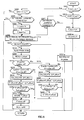
- FIG. 3 is a flowchart illustrating a method of setting a learned correction amount according to the first embodiment of this invention.
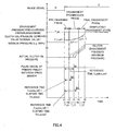
- FIG. 4 is a time chart showing variation in an actual clutch oil pressure when this invention is not used.
- FIG. 5 is a time chart showing variation in the actual clutch oil pressure when this invention is used.
- FIG. 6 is a flowchart illustrating a method of setting a learned correction amount according to a second embodiment of this invention.
- FIG. 7 is a map for calculating a reference correction amount according to the second embodiment of this invention.
- a power train according to a first embodiment of this invention will be described below using the schematic diagram shown in FIG. 1 .
- the power train is mainly constituted by a forward-reverse switching mechanism 4 connected to an engine 1, and a continuously variable transmission 5 connected to an output shaft of the forward-reverse switching mechanism 4.
- the continuously variable transmission 5 comprises an input shaft side primary pulley 10 and a secondary pulley 11 connected to an output shaft 13, which together form a pair of variable pulleys, and the pair of variable pulleys 10, 11 are connected by a V belt (belt) 12.
- the output shaft 13 is connected to a drive shaft 14 via an idler gear and a differential gear.
- start-up elements such as a torque converter are interposed between an input side of the forward-reverse switching mechanism 4 and the engine 1.
- the forward-reverse switching mechanism 4 is constituted by a planetary gear 40 that switches a power transmission path between the engine 1 side and the primary pulley 10, a forward clutch 41, and a reverse clutch 42.
- a forward clutch 41 is engaged, and when the vehicle reverses, the reverse clutch 42 is engaged.
- a neutral position neutral or parking
- both the forward clutch 41 and the reverse clutch 42 are disengaged.
- the engagement state of the forward clutch 41 and reverse clutch 42 is controlled by a clutch pressure adjustment device (oil pressure control unit) 30 that supplies working oil to the forward clutch 41 and reverse clutch 42 at a predetermined oil pressure in accordance with a command from a control unit 20.
- a clutch pressure adjustment device oil pressure control unit 30 that supplies working oil to the forward clutch 41 and reverse clutch 42 at a predetermined oil pressure in accordance with a command from a control unit 20.
- the clutch pressure adjustment device 30 adjusts the oil pressure supplied to the forward clutch 41 and reverse clutch 42 using an oil pressure from a hydraulic pump 15 as a source pressure. Further, the hydraulic pump 15 is connected to the input side of the forward-reverse switching mechanism 4 and so on, and driven by the engine 1.
- the control unit 20 determines an oil pressure command value on the basis of operating conditions and driving operations such as a vehicle speed signal from a vehicle speed sensor 21, a range signal from an inhibitor switch 22 that operates in accordance with a shift lever 17, an engine rotation speed signal from the engine 1 (or an engine control device), and a rotation speed signal relating to the primary pulley 10 from a primary pulley rotation speed sensor (primary pulley rotation speed detection unit) 23, and issues a corresponding command to the clutch pressure adjustment device (oil pressure control unit) 30.
- the clutch pressure adjustment device 30 engages or disengages the forward clutch 41 and reverse clutch 42 by adjusting the oil pressure supplied to the forward clutch 41 and reverse clutch 42 in accordance with the oil pressure command value.
- a speed ratio of the continuously variable transmission 5 and a contact frictional force of the V belt 12 are controlled by a hydraulic control unit (not shown) that operates in accordance with a command from the control unit 20.
- the primary pulley rotation speed sensor 23 that detects the rotation speed of the primary pulley 10 faces an output gear (not shown) attached to the primary pulley 10. Teeth are formed at equal intervals on an outer periphery of the output gear. Therefore, an output waveform detected by the primary pulley rotation speed sensor 23 takes a constant-pitch pulse form at a constant vehicle speed.
- the primary pulley rotation speed sensor 23 is constituted by a pulse sensor that outputs a pulse signal which is synchronous with the rotation of the primary pulley 10.
- a current range signal is read by the inhibitor switch 22.
- a flag to be referred to hereafter as an ND switch flag
- F_nd a flag which indicates whether the shift lever 17 has been switched from the N range to the D range or not.
- step S3 the range signal of the previous control is read and compared to the current range signal read in the step S1. A determination is then made as to whether or not the shift lever 17 has been switched from the N range to the D range.
- the routine advances to a step S4, and when the shift lever 17 has not been switched from the N range to the D range, the routine advances to a step S29.
- the ND switch flag F_nd is switched on. Further, a phase flag F_phase is set at zero, indicating an initialization phase.
- a step S5 nominal values of a pre-charging pressure P_pc, a pre-charging time T_pc, an initial engagement pressure P_start, a first ramp increase rate ⁇ P_r1, a first ramp time T_r1, a second ramp increase rate ⁇ P_r2, and a second ramp time T_r2 are read from the ROM of the control unit 20.
- a learned correction amount P_offset is read from the control unit 20.
- the learned correction amount P_offset is stored in a storage area of a non-volatile rewritable memory such as an EEPROM, for example.
- the learned correction amount P_offset is set at zero. A method of setting the learned correction amount P_offset will be described below.
- the routine advances to a step S8, and when the phase flag F_phase is not at zero, the routine advances to a step S10.
- the ND switch flag F_nd is on and the nominal values have been read, and therefore the phase flag F_phase is set at 1 to indicate a shift to a pre-charging phase.
- a first timer tm_1 for determining an elapsed time of the pre-charging phase is initialized to zero.
- step S10 a determination is made as to whether or not the current phase is the pre-charging phase.
- the routine advances to a step S 11
- the phase flag F_phase is not at 1
- the routine advances to a step S 17.
- step S 11 a determination is made as to whether or not the first timer tm_1 has reached the pre-charging time T_pc read in the step S5.
- the routine advances to a step S12, and when the timer tm_1 has reached the pre-charging time T_pc, the routine advances to a step S14.
- the pre-charging pressure P_pc read in the step S5 is set as a clutch oil pressure command value P_target.
- the pre-charging pressure P_pc is a maximum pressure of the clutch oil pressure command value, by which the inactive stroke of the forward clutch 41 can be reduced quickly.
- step S 13 the first timer tm_1 is incremented.
- the pre-charging phase is complete.
- the phase flag F_phase is set at 2, indicating an engagement progression phase, in the step S14.
- a second timer tm_2 for determining an elapsed time of the engagement progression phase is initialized to zero.
- the clutch oil pressure command value P_target is set at the total value of the initial engagement value P_start read in the step S5 and the learned correction amount P_offset read in the step S6.
- the clutch oil pressure command value P_target is set at a smaller value than the initial engagement value P_start.
- the learned correction amount P_offset is stored using a method to be described in detail below, and by adding (subtracting) the learned correction amount P_offset to (from) the initial engagement value P_start, clutch engagement delays, engagement shock, and so on caused by temporal deterioration of the clutch, product variation, the working oil temperature, and so on can be suppressed.
- phase flag F_phase When it is determined in the step S10 that the phase flag F_phase is not at 1, a determination is made in the step S 17. as to whether or not the current phase is the engagement progression phase. Here, a determination is made as to whether or not the phase flag F_phase is at 2, indicating the engagement progression phase. When the phase flag F_phase is at 2, the routine advances to a step S18, and when the phase flag F_phase is not at 2, the routine advances to a step S24.
- step S 18 a determination is made as to whether or not the second timer tm_2 has reached the first ramp time T_r1 read in the step S5.
- the routine advances to a step S19, and when the second timer tm_2 has reached the first ramp time T_r1, the routine advances to a step S21.
- the clutch oil pressure command value P_target is calculated by adding the first ramp increase rate ⁇ Pr_1 read in the step S5 to a clutch oil pressure command value P_target' of the previous control.
- the clutch oil pressure command value P_target is increased at the first ramp increase rate ⁇ P_r1 in each control cycle from either the initial engagement value P_start or the value obtained by adding (subtracting) the learned correction amount P_offset to (from) the initial engagement value P_start.
- step S20 the second timer tm_2 is incremented.
- the engagement progression phase is complete.
- the phase flag F_phase is set at 3, indicating the final engagement phase.
- a third timer tm_3 for determining an elapsed time of the final engagement phase is initialized to zero.
- the clutch oil pressure command value P_target is calculated by adding the second ramp increase rate ⁇ P_r2 to the clutch oil pressure command value P_target' of the previous control.
- step S24 determines whether or not the third timer tm_3 has reached the second ramp time T_r2 read in the step S5.
- the routine advances to a step S25, and when the third timer tm_3 has reached the second ramp time T_r2, the routine advances to a step S27.
- the clutch oil pressure command value P_target is calculated by adding the second ramp increase rate ⁇ P_r2 to the clutch oil pressure command value P_target' of the previous control.
- step S26 the third timer tm_3 is incremented.
- step S28 the clutch oil pressure command value P_target is set at a normal clutch engagement pressure.
- step S3 When it is determined in the step S3 that the shift lever 17 has not been switched from the N range to the D range, a determination is made in the step S29 as to whether or not the shift lever 17 is in the D range.
- the routine advances to a step S30, and when the shift lever 17 is in the N range, the routine advances to a step S31.
- the clutch oil pressure command value P_target is set at the normal clutch engagement pressure.
- the clutch oil pressure command value P_target is set at a minimum pressure.
- the minimum pressure is 0Mpa, for example.
- step S32 the oil pressure supplied to the forward clutch 41 is controlled to the clutch oil pressure command value P_target set in the control described above by the clutch pressure adjustment device 30.
- the routine advances to a step S102, and when the learning-in-progress flag F_learn is on, the routine advances to a step S 122.
- the learning-in-progress flag F_learn is off, and therefore the routine advances to the step S102.
- the routine advances to a step S103, and when the ND switch flag F_nd remains in the off state or the on state, the current control is terminated.
- step S103 a determination is made as to whether or not a learning condition has been satisfied.
- the learning condition is satisfied when the oil temperature is higher than a predetermined oil temperature and the vehicle is stationary.
- the routine advances to a step S 104, and when the learning condition is not satisfied, the current control is terminated.
- an actual clutch oil pressure which is the pressure actually supplied to the forward clutch 41, increases at a delay relative to variation (increase) in the clutch oil pressure command value P_target.
- the clutch oil pressure command value P_target initial engagement pressure P_start
- the actual clutch oil pressure increases early relative to variation in the clutch oil pressure command value P_target once the oil temperature has entered a normal use temperature region.
- rapid engagement of the forward clutch 41 occurs when the oil temperature reaches a normal use oil temperature.
- learning is not performed.
- the vehicle is determined to be stationary when the primary pulley 10 is in a state of non-rotation, for example when the vehicle speed is Okm/h and a brake switch is on.
- a learning timer tm_pulse is initialized to zero to begin learning of the learned correction amount P_offset.
- the learning timer tm_pulse may be calculated using the first timer, second timer and third timer employed in FIG. 2 .
- step S105 the learning-in-progress flag F_learn is switched on.
- a signal from the primary pulley rotation speed sensor 23 is read.
- the current learning timer (elapsed time) tm_pulse is calculated, whereupon the routine advances to a step S108.
- the routine advances to a step S121.
- the primary pulley 10 When the shift lever 17 is in the N range and the vehicle is stationary, the primary pulley 10 does not rotate and the primary pulley rotation speed sensor 23 does not output a pulse signal. However, when the shift lever 17 shifts from the N range to the D range, torque from the engine 1 is transmitted gradually, whereby the primary pulley 10 rotates. In this case, the primary pulley rotation speed sensor 23 outputs a pulse signal.
- a reference time t_pulse_ref and a reference correction amount ⁇ P_offset are read from the ROM of the control unit 20.
- the reference time t_pulse_ref is a time extending from a point at which the ND switch flag F_nd switches from off to on to a point at which the primary pulley rotation speed sensor 23 outputs a pulse signal when temporal deterioration or the like has not occurred in the forward clutch 41 and so on.
- the reference correction amount ⁇ P_offset is a preset value by which the learned correction amount P_offset is corrected in a single learning correction operation when an absolute value of a deviation between the learning timer tm_pulse and the reference time t_pulse_ref is large.
- the learned correction amount P_offset is read from the storage area of the control unit 20 (hereafter, the learned correction amount P_offset read in the step S109 will be referred to as P_offset').
- the learned correction amount P_offset' is set at zero.
- a step S110 the learning timer tm_pulse at the time of pulse signal output from the primary pulley rotation speed sensor 23 is compared with the reference time t_pulse_ref.
- the routine advances to a step S111, and when the learning timer tm_pulse is smaller than the reference time t_pulse_ref, the routine advances to a step S 117.
- step S111 a determination is made as to whether or not the absolute value of the deviation between the learning timer tm_pulse and the reference time t_pulse_ref is greater than a predetermined threshold ⁇ t_pulse_dif.
- the routine advances to a step S 112 and when the absolute value is smaller than the predetermined threshold ⁇ t_pulse_dif, the routine advances to a step S 115.
- the routine advances to the step S115, in which the current learned correction amount P_offset is maintained.
- modification of the learned correction amount P_offset due to a detection error or the like can be prevented.
- hunting in the learned correction amount P_offset or in other words hunting in the engagement timing of the forward clutch 41, can be prevented.
- the predetermined threshold ⁇ t_pulse_dif is set at a value for preventing the effects of detection errors and preventing hunting in the learned correction amount P_offset.
- the learning timer tm_pulse is determined to be larger than the reference time t_pulse_ref, and therefore, when the deviation between the learning timer tm_pulse and the reference time t_pulse_ref is calculated, the value of the deviation takes a positive sign.
- the threshold ⁇ t_pulse_dif may be set at a positive value without calculating the absolute value of the deviation, and then compared thereto.
- the reference correction amount ⁇ P_offset is added to the learned correction amount P_offset' read in the step S109, and the result is updated to the learned correction amount P_offset.
- the absolute value of the deviation between the learning timer tm_pulse and the reference time t_pulse_ref is larger than the predetermined threshold ⁇ t_pulse_dif, the current learned correction amount P_offset' is updated, thereby preventing a delay in engagement of the forward clutch 41.
- the routine advances to a step S114, and when the learned correction amount P_offset is larger than the correction amount upper limit value P_offset_uplimit, the routine advances to the step S115.
- the learned correction amount P_offset is larger than the correction amount upper limit value P_offset_uplimit, the updated learned correction amount P_offset is not stored in the storage area of the control unit 20.
- step S 114 the updated learned correction amount P_offset is stored in the storage area of the control unit 20. Thereafter, the value stored in the storage area of the control unit 20 is used as the learned correction amount P_offset.
- step S115 the learning-in-progress flag F_learn is switched off. As a result, the learning control is terminated.
- step S 116 the learning timer tm_pulse is initialized to zero.
- the routine advances to a step S 118, and when the absolute value is smaller than predetermined threshold ⁇ t_pulse_dif, the routine advances to the step S 115.
- the learning timer tm_pulse is determined to be smaller than the reference time t_pulse_ref, and therefore, when the deviation between the learning timer tm_pulse and the reference time t_pulse_ref is calculated, the value of the deviation takes a negative sign.
- the threshold ⁇ t_pulse_dif may be set at a negative value without calculating the absolute value of the deviation, and then compared thereto. At this time, when the threshold ⁇ t_pulse_dif is set at a negative value and the deviation is larger than the threshold in a negative direction, the routine advances to the step S 118.
- the threshold of the step S111 and the threshold of the step S 117 may take different values or values that differ only in their sign.
- the reference correction amount ⁇ P_offset is subtracted from the learned correction amount P_offset' read in the step S109, and the result is updated to the learned correction amount P_offset.
- the absolute value of the deviation between the learning timer tm_pulse and the reference time t_pulse_ref is smaller than the predetermined threshold ⁇ t_pulse_dif, the current learned correction amount P_offset' is updated, thereby preventing rapid engagement of the forward clutch 41.
- the routine advances to a step S120, and when the learned correction amount P_offset is smaller than the correction amount lower limit value P_offset_unlimit, the routine advances to the step S 115.
- the learned correction amount P_offset is smaller than the correction amount lower limit value P_offset_unlimit, the updated learned correction amount P_offset is not stored in the storage area of the control unit 20.
- the learned correction amount P_offset is a numerical value having a sign, and therefore the correction amount lower limit value P_offset_unlimit is a negative-side limit value. Therefore, when the correction amount upper limit value P_offset_uplimit and the correction amount lower limit value P_offset_unlimit are set at an identical value, the absolute value of the learned correction amount P_offset is compared to the absolute value of the correction amount lower limit value P_offset_unlimit in the step S 119, and when the absolute value of the learned correction amount P_offset is smaller than the absolute value of the correction amount lower limit value P_offset_unlimit, the routine advances to the step S120.
- the updated learned correction amount P_offset is stored in the storage area of the control unit 20. Thereafter, the value stored in the storage area of the control unit 20 is used as the learned correction amount P_offset.
- the learning timer tm_pulse is incremented in the step S 121.
- step S101 When the learning-in-progress flag F_learn is determined to be on in the step S101, a determination is made in the step S122 as to whether or not the ND switch flag F_nd has switched from on to off.
- the routine advances to a step S123, and when the ND switch flag F_nd has not switched from on to off, the routine advances to a step S125.
- step S123 the learning-in-progress flag F_learn is switched off.
- learning of the learned correction amount P_offset is halted and the learning processing is terminated in cases such as when a switch from the N range to the D range is halted after learning has begun.
- step S124 the learning timer tm_pulse is initialized to zero.
- step S125 When no variation is determined in the ND switch flag F_nd in the step S122, a determination is made in the step S125 as to whether or not the learning condition is established.
- the learning condition is identical to that of the step S103.
- the routine advances to the step S106, in which learning is continued, and when the learning condition is not established, the routine advances to the step S123.
- the learning timer tm_pulse up to the point at which a pulse signal is output from the primary pulley rotation speed sensor 23 is calculated.
- the learned correction amount P_offset is then calculated on the basis of the calculated learning timer tm_pulse and stored in the storage area of the control unit 20.
- the clutch oil pressure command value P_target is then calculated on the basis of the stored learned correction amount P_offset, and by controlling the oil pressure, engagement delays and engagement shock due to rapid engagement can be prevented in the forward clutch 41.
- FIG. 4 is a time chart showing variation in the actual clutch oil pressure when this invention is not used
- FIG. 5 is a time chart showing variation in the actual clutch oil pressure when this invention is used.
- the clutch oil pressure command value P_target is set at the pre-charging pressure P_pc to reduce the inactive stroke part of the forward clutch 41.
- the clutch oil pressure command value P_target is set at the nominal value and increased from the nominal value at the first ramp increase rate ⁇ P_r1.
- the second timer tm_2 reaches the first ramp time T_r1 such that the final engagement phase begins, and at a time t5, the third timer tm_3 reaches the second ramp time T_r2, at which point the forward clutch 41 is completely engaged.
- the time at which a pulse signal is output by the primary pulley rotation speed sensor 23 is calculated as the learning timer tm_pulse, and the learned correction amount P_offset is learned on the basis of the learning timer tm_pulse.
- the learned correction amount P_offset can be learned even when a turbine rotation speed sensor is not used.
- the clutch oil pressure command value P_target is reduced or increased at the time t2, i.e. at the start of the engagement progression phase, and as a result, variation in the actual clutch oil pressure can be made substantially identical to variation in the nominal value.
- the time at which the primary pulley rotation speed sensor 23 outputs a pulse signal thereafter is the time t3.
- the learned correction amount P_offset is learned again, and therefore the learned correction amount P_offset can be updated appropriately.
- the learned correction amount P_offset which is an oil pressure correction amount to be used during clutch engagement
- the learned correction amount P_offset can be updated even when a turbine rotation speed sensor is not used, and as a result, clutch engagement delays and engagement shock caused by temporal variation, product variation, the working oil temperature, and so on can be suppressed.
- the number of components can be reduced, enabling a reduction in cost.
- a new learned correction amount P_offset is calculated by adding the reference correction amount ⁇ P_offset to the current learned correction amount P_offset' when the learning timer tm_pulse is longer than the reference time t_pulse_ref and subtracting the reference correction amount ⁇ P_offset from the current learned correction amount P_offset when the learning timer tm_pulse is shorter than the reference time t_pulse_ref.
- the learned correction amount P_offset can be calculated easily.
- a part of the method of setting the learned correction amount P_offset differs from that of the first embodiment, but all other constitutions and control are identical to the first embodiment, and therefore description thereof has been omitted.
- Control performed from a step S201 to a step S207 is identical to the control of the steps S101 to S107 in FIG. 3 , and therefore description thereof has been omitted.
- a step S208 the reference time t_pulse_ref is read from the ROM of the control unit 20.
- Control performed from a step S209 to a step S211 is identical to the control of the steps S109 to S111 in FIG. 3 , and therefore description thereof has been omitted.
- the reference correction amount ⁇ P_offset is calculated on the basis of the absolute value of the deviation between the learning timer tm_pulse and the reference time t_pulse_ref from a map shown in FIG. 7 .
- the reference correction amount ⁇ P_offset increases as the absolute value of the deviation between the learning timer tm_pulse and the reference time t_pulse_ref increases.
- Control performed from a step S213 to a step S218 is identical to the control of the steps S112 to S117 in FIG. 3 , and therefore description thereof has been omitted.
- a step S213 the reference correction amount ⁇ P_offset calculated in the step S212 is used.
- a step S219 similarly to the step S212, the reference correction amount ⁇ P_offset is calculated from the map shown in FIG. 7 .
- Control performed from a step S220 to a step S227 is identical to the control of the steps S118 to S125 in FIG. 3 , and therefore description thereof has been omitted.
- the reference correction amount ⁇ P_offset is calculated on the basis of the absolute value of the deviation between the learning timer tm_pulse and the reference time t_pulse_ref, and therefore the learned correction amount P_offset can be calculated accurately.
Landscapes
- Engineering & Computer Science (AREA)
- General Engineering & Computer Science (AREA)
- Mechanical Engineering (AREA)
- Physics & Mathematics (AREA)
- Fluid Mechanics (AREA)
- Control Of Transmission Device (AREA)
Applications Claiming Priority (1)
| Application Number | Priority Date | Filing Date | Title |
|---|---|---|---|
| JP2008068117A JP2009222155A (ja) | 2008-03-17 | 2008-03-17 | 無段変速機の制御装置 |
Publications (2)
| Publication Number | Publication Date |
|---|---|
| EP2103847A2 true EP2103847A2 (de) | 2009-09-23 |
| EP2103847A3 EP2103847A3 (de) | 2010-01-06 |
Family
ID=40790802
Family Applications (1)
| Application Number | Title | Priority Date | Filing Date |
|---|---|---|---|
| EP08022041A Withdrawn EP2103847A3 (de) | 2008-03-17 | 2008-12-18 | Steuereinrichtung für stufenlos verstellbares Getriebe und Steuerungsverfahren hierfür |
Country Status (5)
| Country | Link |
|---|---|
| US (1) | US20090240410A1 (de) |
| EP (1) | EP2103847A3 (de) |
| JP (1) | JP2009222155A (de) |
| KR (1) | KR20090099476A (de) |
| CN (1) | CN101539198A (de) |
Cited By (1)
| Publication number | Priority date | Publication date | Assignee | Title |
|---|---|---|---|---|
| EP3196512A1 (de) * | 2016-01-20 | 2017-07-26 | Toyota Jidosha Kabushiki Kaisha | Steuerungsvorrichtung und steuerungsverfahren für fahrzeugantriebsstrang |
Families Citing this family (8)
| Publication number | Priority date | Publication date | Assignee | Title |
|---|---|---|---|---|
| JP5647488B2 (ja) * | 2010-10-29 | 2014-12-24 | ダイハツ工業株式会社 | 車両用制御装置 |
| JP5659026B2 (ja) * | 2011-01-14 | 2015-01-28 | 日本精工株式会社 | 無段変速装置 |
| EP2752599A4 (de) * | 2011-08-31 | 2016-07-06 | Jatco Ltd | Fahrzeugsteuerungsvorrichtung |
| KR101600215B1 (ko) * | 2011-11-17 | 2016-03-04 | 쟈트코 가부시키가이샤 | 자동 변속기 및 자동 변속기의 셀렉트 조작 판단 방법 |
| KR101669743B1 (ko) * | 2012-03-28 | 2016-10-27 | 쟈트코 가부시키가이샤 | 자동 변속기 및 그 제어 방법 |
| WO2015060204A1 (ja) * | 2013-10-23 | 2015-04-30 | ジヤトコ株式会社 | 無段変速機の制御装置 |
| CN111051745B (zh) * | 2017-08-23 | 2021-06-11 | 日产自动车株式会社 | 无级变速器的控制方法以及控制装置 |
| CN111350773B (zh) * | 2018-12-24 | 2021-09-21 | 长城汽车股份有限公司 | 离合器的压力补偿控制方法、系统及车辆 |
Citations (1)
| Publication number | Priority date | Publication date | Assignee | Title |
|---|---|---|---|---|
| JP2008068117A (ja) | 2007-10-25 | 2008-03-27 | Sankyo Kk | 遊技機 |
Family Cites Families (8)
| Publication number | Priority date | Publication date | Assignee | Title |
|---|---|---|---|---|
| JP3055346B2 (ja) * | 1993-03-08 | 2000-06-26 | 日産自動車株式会社 | 自動変速機のセレクトショック軽減装置 |
| JP2000161478A (ja) * | 1998-11-20 | 2000-06-16 | Fuji Heavy Ind Ltd | 自動変速装置の制御装置 |
| JP3730204B2 (ja) * | 2002-09-02 | 2005-12-21 | ジヤトコ株式会社 | ベルト式無段変速機のベルト滑り防止システム |
| JP4055566B2 (ja) * | 2002-12-05 | 2008-03-05 | トヨタ自動車株式会社 | 自動変速機の制御装置 |
| JP4296957B2 (ja) * | 2004-02-18 | 2009-07-15 | トヨタ自動車株式会社 | 車両用無段変速機の制御装置 |
| JP4145856B2 (ja) * | 2004-10-05 | 2008-09-03 | ジヤトコ株式会社 | ベルト式無段変速機のライン圧制御装置 |
| JP2008106814A (ja) * | 2006-10-24 | 2008-05-08 | Jatco Ltd | ベルト式無段変速機の油圧制御装置 |
| JP4464994B2 (ja) * | 2007-07-06 | 2010-05-19 | ジヤトコ株式会社 | 自動変速機の油圧制御装置 |
-
2008
- 2008-03-17 JP JP2008068117A patent/JP2009222155A/ja active Pending
- 2008-12-18 EP EP08022041A patent/EP2103847A3/de not_active Withdrawn
-
2009
- 2009-02-12 US US12/370,320 patent/US20090240410A1/en not_active Abandoned
- 2009-03-11 CN CN200910127440A patent/CN101539198A/zh active Pending
- 2009-03-16 KR KR1020090021954A patent/KR20090099476A/ko not_active Withdrawn
Patent Citations (1)
| Publication number | Priority date | Publication date | Assignee | Title |
|---|---|---|---|---|
| JP2008068117A (ja) | 2007-10-25 | 2008-03-27 | Sankyo Kk | 遊技機 |
Cited By (1)
| Publication number | Priority date | Publication date | Assignee | Title |
|---|---|---|---|---|
| EP3196512A1 (de) * | 2016-01-20 | 2017-07-26 | Toyota Jidosha Kabushiki Kaisha | Steuerungsvorrichtung und steuerungsverfahren für fahrzeugantriebsstrang |
Also Published As
| Publication number | Publication date |
|---|---|
| CN101539198A (zh) | 2009-09-23 |
| EP2103847A3 (de) | 2010-01-06 |
| US20090240410A1 (en) | 2009-09-24 |
| KR20090099476A (ko) | 2009-09-22 |
| JP2009222155A (ja) | 2009-10-01 |
Similar Documents
| Publication | Publication Date | Title |
|---|---|---|
| EP2103847A2 (de) | Steuereinrichtung für stufenlos verstellbares Getriebe und Steuerungsverfahren hierfür | |
| KR101342332B1 (ko) | 벨트식 무단 변속기의 유압 제어 장치 | |
| KR101363307B1 (ko) | 벨트식 무단 변속기의 변속 제어 장치 | |
| US20110203411A1 (en) | Oil temperature correction device and method for automatic transmission | |
| EP2503196B1 (de) | Stufenloses Getriebe und zugehöriges Steuerungsverfahren | |
| KR20100106928A (ko) | 벨트식 무단 변속기 및 그 변속 제어 방법 | |
| KR101597067B1 (ko) | 자동 변속기 및 그 발진시 제어 방법 | |
| JP2004084856A (ja) | 車両用変速機の油圧制御装置 | |
| US9995389B2 (en) | Continuously variable transmission control device and control method | |
| JP4641852B2 (ja) | ベルト式無段変速機の変速制御装置 | |
| KR20080036922A (ko) | 벨트식 무단 변속기의 유압 제어 장치 | |
| EP2151595A1 (de) | Vorrichtung zur Kupplungssteuerung | |
| JP4072200B2 (ja) | ベルト式無段変速機の制御装置 | |
| EP2833028B1 (de) | Stufenloses getriebe und hydraulikdrucksteuerungsverfahren dafür | |
| US7001299B2 (en) | Control apparatus of automatic transmission | |
| US7558660B2 (en) | Continuously variable transmission and control method thereof | |
| JP2792200B2 (ja) | 車両用自動変速機の変速制御装置 | |
| JP2004125063A (ja) | ベルト式無段変速機の制御装置 | |
| JP4141377B2 (ja) | ベルト式無段変速機 | |
| JP5096559B2 (ja) | 無段変速機の制御装置 | |
| JP4611661B2 (ja) | 自動変速機の制御方法及び制御装置 | |
| JP4418436B2 (ja) | 車両用ベルト式無段変速システムの油圧制御装置 | |
| JP4875408B2 (ja) | ベルト式無段変速機搭載車両の制御装置 | |
| JP5379049B2 (ja) | 自動変速機の制御装置 | |
| JP2008039154A (ja) | ベルト式無段変速機における油圧制御装置 |
Legal Events
| Date | Code | Title | Description |
|---|---|---|---|
| PUAI | Public reference made under article 153(3) epc to a published international application that has entered the european phase |
Free format text: ORIGINAL CODE: 0009012 |
|
| AK | Designated contracting states |
Kind code of ref document: A2 Designated state(s): AT BE BG CH CY CZ DE DK EE ES FI FR GB GR HR HU IE IS IT LI LT LU LV MC MT NL NO PL PT RO SE SI SK TR |
|
| AX | Request for extension of the european patent |
Extension state: AL BA MK RS |
|
| PUAL | Search report despatched |
Free format text: ORIGINAL CODE: 0009013 |
|
| AK | Designated contracting states |
Kind code of ref document: A3 Designated state(s): AT BE BG CH CY CZ DE DK EE ES FI FR GB GR HR HU IE IS IT LI LT LU LV MC MT NL NO PL PT RO SE SI SK TR |
|
| AX | Request for extension of the european patent |
Extension state: AL BA MK RS |
|
| 17P | Request for examination filed |
Effective date: 20100331 |
|
| GRAP | Despatch of communication of intention to grant a patent |
Free format text: ORIGINAL CODE: EPIDOSNIGR1 |
|
| GRAJ | Information related to disapproval of communication of intention to grant by the applicant or resumption of examination proceedings by the epo deleted |
Free format text: ORIGINAL CODE: EPIDOSDIGR1 |
|
| AKX | Designation fees paid |
Designated state(s): DE FR GB IT |
|
| RIC1 | Information provided on ipc code assigned before grant |
Ipc: F16D 48/06 20060101AFI20100802BHEP |
|
| STAA | Information on the status of an ep patent application or granted ep patent |
Free format text: STATUS: THE APPLICATION HAS BEEN WITHDRAWN |
|
| 18W | Application withdrawn |
Effective date: 20100813 |